Embed Size (px)
Citation preview
THE DEVELOPMENT AND IMPLEMENTATION OF THE LONMIN MECHANIZED BREAST MINING 107
IntroductionThe purpose of this paper is to describe the process ofdeveloping and applying new technology to stopingsystems in the South African narrow reef mining industrybecause for the last hundred years the South African narrowreef mining industry has battled to control working costs ina labour intensive industry; and because it is the stopingmethod and mining methodology that are at the heart of themining system. Introduce a more efficient stoping systemand the mining system will look after itself. The technologycurrently used and applied to stoping over the last 100 yearscan be categorized as follows:
• The introduction of pneumatic rock drills early in thelast century, the cumbersome rig mounted units beingreplaced by smaller, lighter hand-held units that werethen made easier to use with the addition of an air leg.Water hydraulic rockdrills were introduced in the1980s; they have the advantage of being twice thepower of pneumatic rockdrills and operating at a lowernoise level. The most recent rockdrill development isthe electric rockdrill.
• Scraper winches to replace gravity and shovels to moverock — both in the face and the gullies — were firstintroduced in the late 1920s.
• Hydraulic props as a support method arrived in the1960s.
• Some people argue that tungsten carbide inserts wereequally important.
There have been a number of attempts to introducedifferent technologies into stoping, the most recent beingtrackless equipment. Where the stoping layout suits thetechnology it has been successful. There have been toomany instances where a technology has been installedbecause it is fashionable.
At the end of the day the outcome from implementingchange in the stoping system has to be safer and moreprofitable mining systems. It is the contention of theauthors that change is only likely to be effective if theapplication of new technology is supported by theintroduction and application of new mining layouts.
Details of the process in the development of the UltraLow Profile suite of trackless mining equipment developed
through the Lonmin Sandvik partnership, primarily for thenarrow reef, hard rock, South African platinum miningindustry, are given in this paper. Together with details of anew mining layout that is currently being implemented byLonmin Platinum.
Project 1,1Right from the outset it was identified that the objective ofthis project was to develop a mechanized mining systemthat could operate in a narrow reef, hard rock miningenvironment having a stope width of 1.1 metres. The suiteof equipment developed was known as the Xtra Low Profile(XLP) or Ultra Low Profile (ULP).
The following section describes the steps taken during thedevelopment of the technology and the interaction betweenpotential end users (the mines), the manufacturers (theprocos) and Sandvik South Africa who acted as thefacilitator and choirmaster.
The customer Sandvik partnershipA key element to the success of this development has beenthe high level of trust exhibited between Lonmin Platinumand Sandvik. This is best demonstrated by describing anevent that took place towards the end of 2001.
Sandvik and Voest Alpine had developed the concept of ahard rock cutting machine, primarily for use in the platinummines of South Africa. This was in response to thegenerally held view of the platinum producers thatcontinuous, non-explosive, mechanized mining was the potof gold at the end of the rainbow.
This conceptual design was presented to LonminPlatinum and through this the beginnings of the uniquepartnership were formed. They then visited Zeltweg andmet with the Voest Alpine management and designers. Themeeting went well but the obvious stumbling block washow to fund the design, manufacture and test of the firstprototype. The chief executive of Lonmin then committedhis organisation to purchase the first prototype, provide atest venue at his cost and pay for 50% of the trial costs.
Throughout the early part of 2001 there was extensiveinteraction between the customer, the proco and Sandvik.The result was that the prototype machine was operating ina test stope by the end of September 2001.
PICKERING, R.G.B., and MOXHAM, K. The development and implementation of the Lonmin mechanized breast mining. International PlatinumConference ‘Platinum Surges Ahead’, The Southern African Institute of Mining and Metallurgy, 2006.
The development and implementation of the Lonminmechanized breast mining
R.G.B. PICKERING and K. MOXHAMSandvik Tamrock and Lonmin Platinum
Over the last few years Lonmin Platinum and Sandvik have embarked on a unique partnership ofcollaboration through a systematic approach to developing equipment to mechanize and automatenarrow reef platinum mining. After the initial design and manufacture of the equipment the keyaspect is the integrating equipment, people and method into a mining system. Another key aspectof mechanization is the optimization of equipment utilization and this philosophy has ensuredcontinual evolvement of mining methods. This paper describes the trials and development thathave resulted in the mining method described as Lonmin mechanized breast.
PLATINUM SURGES AHEAD108
It was about this time that the objective of developing amore conventional mechanized mining fleet for drill andblast mining was also identified.
Sandvik has made a conscious effort to understand thecustomer’s business at least as well as the customer. Theproduction people on the mine concentrate on productionand not on change. If Sandvik had concentrated only onselling equipment, then no one is pushing change. Sandvikhas made every effort to understand the customer’sperformance measures and how they could be improved.
The proco Sandvik partnershipA second key element to the success of this developmenthas also been the high level of trust exhibited between theSandvik equipment manufacturers and the marketing teamin South Africa. This partnership also has its roots goingback some distance. The more traditional way that theprocos and the marketing organizations have interacted isthrough the international offering team meetings where theprocos would interact with all the different Sandvikmarketing regions and attempt to identify what direction totake for the next generation of equipment. This strategyresults in the sales/marketing organization concentrating onthe placement of the procos’ products into an existingmining infrastructure.
In asking the Lyon factory to produce a low profile (LP)face drill rig for the chrome mines Sandvik moved in adifferent direction. The first four rigs were delivered toSouth Africa in early 1999. By the end of 1999 theproductivity of the rig had been demonstrated andadditional rigs were on order. The need for acomplementary loader had been highlighted and, followingsome design work by EJC, a number of EJC 115s had beenordered. By the end of 2000 orders from Sandvik for thenew drill rig and loader accounted for a substantial part ofthe business of both Lyon and EJC. This strategy ofunderstanding the mining process and developingappropriate technology to match the mining process was afirst for South Africa.
Good relations had been developed between Sandvik andthe procos. When Sandvik, in collaboration with Lonmin,identified the need for a new suite of equipment to operatein a stope height of 1.1 metres the procos were receptive.
It is interesting to note that the platinum mines hadpicked up on the low profile equipment developed from thechrome mines and had started to implement low profileroom and pillar mining. The difference in the orebodies,chrome with a channel width of 1.65 metres and UG2platinum with a channel width of 0.8 metres, resulted inlower shaft head grade and lower precious metal recoveries.The LP suite of equipment has been very successfully used,especially in development at mines like Union Section.Aquarius has also been very successful in applying the LPequipment to narrow reef mining for platinum.
Recognizing need
The need for mechanization in the platinum mines is drivenprimarily by the recognition that it is getting more difficultto recruit handheld rock drill operators. The job involveshard physical effort and has lost the ‘macho’ status that itonce occupied. HIV/AIDS is also an issue with probably upto 50% of the workforce being infected; when you feel sickthe last thing on your mind is hard physical effort. Theaverage age of the current rock drill operator work force isgreater than 45 and the high noise levels have resulted inever increasing occupational health costs. The job is also
very dangerous and 25% of the platinum miningincidents/accidents occur within 5 metres of the face.
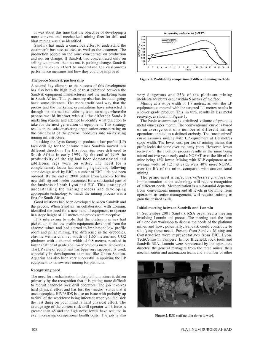
Mining at a stope width of 1.8 metres, as with the LPequipment, compared with the targeted 1.1 metres results ina lower grade product. This, in turn, results in less metalrecovery, as shown in Figure 1.
The basic assumption is a defined volume of preciousmetal ounces per month. The ‘conventional’ curve is basedon an average cost of a number of different miningoperations applied to a defined orebody. The ‘mechanized’curve assumes mining with LP equipment at 1.8 metresstope width. The lower cost per ton of mining means thatprofit looks the same over the early years. However, lowerrecovery in the flotation process results in the mine beingmined out two years early and a NOPAT over the life of themine being 18% lower. Mining with XLP equipment at anaverage width of 1.2 metres delivers 40% more NOPATover the life of the mine, compared with conventionalmining.
The prime need is safe, cost-effective production.Implementation of the technology will require recognitionof different needs. Mechanization is a substantial departurefrom conventional mining and all levels in the mine, fromoperators to senior management, will require training togain the desired skills.
Initial meeting between Sandvik and LonminIn September 2001 Sandvik RSA organized a meetinginvolving Lonmin and procos. The meeting took the formof a one day workshop to discuss the needs of the platinummines and how, potentially, Sandvik could contribute tosatisfying these needs. Present from Sandvik Mining andConstruction were representatives from EJC, Lyon,TechCentre in Tampere, Eimco Bluefield, rock tools andSandvik RSA. Lonmin were represented by the operationsdirector, the general managers from the three mines, theirmechanization and automation team, and a number of other
Figure 1. Profitability comparison of different mining methods
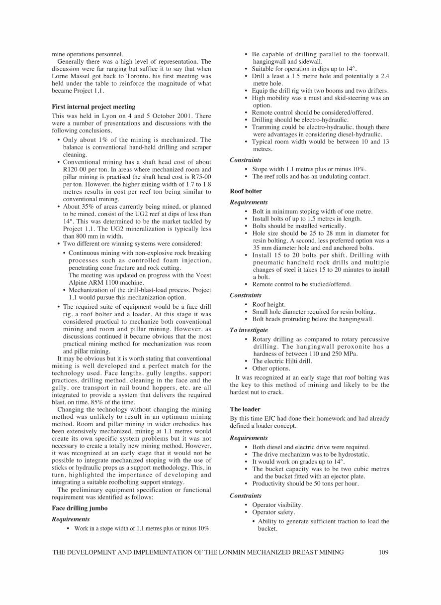
Figure 2. EJC staff getting down to work
THE DEVELOPMENT AND IMPLEMENTATION OF THE LONMIN MECHANIZED BREAST MINING 109
mine operations personnel.Generally there was a high level of representation. The
discussion were far ranging but suffice it to say that whenLorne Massel got back to Toronto, his first meeting washeld under the table to reinforce the magnitude of whatbecame Project 1,1.
First internal project meetingThis was held in Lyon on 4 and 5 October 2001. Therewere a number of presentations and discussions with thefollowing conclusions.
• Only about 1% of the mining is mechanized. Thebalance is conventional hand-held drilling and scrapercleaning.
• Conventional mining has a shaft head cost of aboutR120-00 per ton. In areas where mechanized room andpillar mining is practised the shaft head cost is R75-00per ton. However, the higher mining width of 1.7 to 1.8metres results in cost per reef ton being similar toconventional mining.
• About 35% of areas currently being mined, or plannedto be mined, consist of the UG2 reef at dips of less than14°. This was determined to be the market tackled byProject 1,1. The UG2 mineralization is typically lessthan 800 mm in width.
• Two different ore winning systems were considered:
• Continuous mining with non-explosive rock breakingprocesses such as controlled foam injection,penetrating cone fracture and rock cutting.The meeting was updated on progress with the VoestAlpine ARM 1100 machine.
• Mechanization of the drill-blast-load process. Project1,1 would pursue this mechanization option.
• The required suite of equipment would be a face drillrig, a roof bolter and a loader. At this stage it wasconsidered practical to mechanize both conventionalmining and room and pillar mining. However, asdiscussions continued it became obvious that the mostpractical mining method for mechanization was roomand pillar mining.
It may be obvious but it is worth stating that conventionalmining is well developed and a perfect match for thetechnology used. Face lengths, gully lengths, supportpractices, drilling method, cleaning in the face and thegully, ore transport in rail bound hoppers, etc. are allintegrated to provide a system that delivers the requiredblast, on time, 85% of the time.
Changing the technology without changing the miningmethod was unlikely to result in an optimum miningmethod. Room and pillar mining in wider orebodies hasbeen extensively mechanized, mining at 1.1 metres wouldcreate its own specific system problems but it was notnecessary to create a totally new mining method. However,it was recognized at an early stage that it would not bepossible to integrate mechanized stoping with the use ofsticks or hydraulic props as a support methodology. This, inturn, highlighted the importance of developing andintegrating a suitable roofbolting support strategy.
The preliminary equipment specification or functionalrequirement was identified as follows:
Face drilling jumbo
Requirements• Work in a stope width of 1.1 metres plus or minus 10%.
• Be capable of drilling parallel to the footwall,hangingwall and sidewall.
• Suitable for operation in dips up to 14°.• Drill a least a 1.5 metre hole and potentially a 2.4
metre hole.• Equip the drill rig with two booms and two drifters.• High mobility was a must and skid-steering was an
option.• Remote control should be considered/offered.• Drilling should be electro-hydraulic.• Tramming could be electro-hydraulic, though there
were advantages in considering diesel-hydraulic.• Typical room width would be between 10 and 13
metres.
Constraints• Stope width 1.1 metres plus or minus 10%.• The reef rolls and has an undulating contact.
Roof bolter
Requirements• Bolt in minimum stoping width of one metre.• Install bolts of up to 1.5 metres in length.• Bolts should be installed vertically.• Hole size should be 25 to 28 mm in diameter for
resin bolting. A second, less preferred option was a35 mm diameter hole and end anchored bolts.
• Install 15 to 20 bolts per shift. Drilling withpneumatic handheld rock drills and multiplechanges of steel it takes 15 to 20 minutes to installa bolt.
• Remote control to be studied/offered.
Constraints• Roof height.• Small hole diameter required for resin bolting.• Bolt heads protruding below the hangingwall.
To investigate• Rotary drilling as compared to rotary percussive
drilling. The hangingwall peroxonite has ahardness of between 110 and 250 MPa.
• The electric Hilti drill.• Other options.
It was recognized at an early stage that roof bolting wasthe key to this method of mining and likely to be thehardest nut to crack.
The loaderBy this time EJC had done their homework and had alreadydefined a loader concept.
Requirements• Both diesel and electric drive were required.• The drive mechanizm was to be hydrostatic.• It would work on grades up to 14°.• The bucket capacity was to be two cubic metres
and the bucket fitted with an ejector plate.• Productivity should be 50 tons per hour.
Constraints• Operator visibility.• Operator safety.
• Ability to generate sufficient traction to load thebucket.
PLATINUM SURGES AHEAD110
Initial calculations suggested that with a fleet of one facedrill, one roof bolter and two LHDs it would be possible toachieve a production rate of 16 000 tons per month.
Second internal project meetingHeld in Lyon on 24 and 25 January 2002. Prior to thismeeting a visit had been arranged and a report had beenprepared on the two sections of the mines that were usingsemi-mechanized narrow reef mining. The findings aresummarized below.
Bleskop SectionThey were mining UG2 reef at a rate of 3 000 tons permonth at a mining width of between one and 1,2 metres.Drilling was by hand and holes were 1.2 metres long.Support by roof bolts on a 1.5 x 1.0 metre pattern, boltswere 1.5 metres long, end anchored and installed by hand.
Cleaning was with two Long Airdox battery coal scoops.Scoop size was about 2.5 metres by 8 metres with amaximum height of one metre above the tyres. All tyreswere fitted with chains.
Bafokeng Rasimone.This is a section mined from surface. Access is via adecline straight of the highwall. Access development on dipand strike is carried out with two Axera LP drill rigs andtwo EJC 115s. Mining is in the Merensky Reef. The minehad been started by a contractor who had recently beenremoved from the site and the mine was now picking up thepieces. Drilling was by hand.
Roof bolting on a 1.5 x 1.5 metre pattern using a Fletcherroofbolter from the coalmines, approximate dimensionswere 0.8 x 2.2 x 5 metres. Cleaning was with a LongAirdox coal scoop. The size of the unit was 0,85 metres
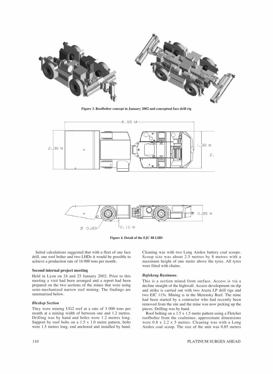
Figure 3. Roofbolter concept in January 2002 and conceptual face drill rig
Figure 4. Detail of the EJC 88 LHD
THE DEVELOPMENT AND IMPLEMENTATION OF THE LONMIN MECHANIZED BREAST MINING 111
over the canopy with a foot print of 3 metres by 8 metres.Volume of the bucket was 1.7 m3.
They had five scoops and had just ordered a sixth for aplanned production rate of 50 000 tons per month (currentproduction was closer to 25 000 tons per month).
Loading was by pushing into the rock pile. There was nodigging or breakout action, and all scoops were fitted withchains. When loading, the bucket was pushed down ontothe uneven footwall, lifting the front wheels off thefootwall.
Ventilation in this kind of room and pillar mining waspoor.
Following this study it was recommended that theproduction target for a suite of equipment in Project 1,1should be 10 000 tons per month.
The outcomes from this meeting included the following:• Success with the roofbolter development was identified
as the key to overall project success. The bolterrequirements were defined as:• Installation of 1.5 to 1.6 metres long, 20 mm
diameter, resin grouted bolts.• An investigation into the practicalities of developing
a shorter drifter.• A more detailed evaluation to be conducted
comparing rotary drilling with rotary percussivedrilling.
• Concept drawings of the face drill, roof bolter and LHDwere considered.
• It is interesting to note that the EJC 88 has a footprintof 14 m2 compared with the 24 m2 of the Long Airdoxbattery scoop.
• It was generally considered that we were going in theright direction and that conceptually we were on theright track to address the mines’ requirements.
• The requirements for a utility trailer and a cablehandling system were also identified.
The second day was spent discussing the marketingstrategy and it was decided that the marketing plan shouldbe in place by the end of April. Issues discussed includedthe following:
• With Project 1,1 we are not selling equipment but anew mining system and a solution to the perceivedsocio-economic problems facing the narrow reef, hardrock mining sector. The new mining system should besafer and more productive, resulting in increasedbenefits for all shareholders and stakeholders.
• Identification of trial sites and customers who wouldmake a quality commitment to the ‘productionization’of the prototype units.
• Patent protection.• Sending service technicians from South Africa to both
EJC and Lyon.• Comparative cost of Long Airdox units.• Selection and training of operators for the mine trials
— includes training of trainers.• Recommended spares parts lists.• Field engineer from procos on site during testing.
Third internal project meetingThis meeting was held in Johannesburg on 9 and 10 April2002. The interaction between procos and Sandvik RSA ispart of the Sandvik business model. There is frequentinteraction and visiting between the various organizations.However, on this occasion every effort was made to exposethose responsible for designing the equipment to theunderground environment.
The other internal change that had been made was theestablishment of a separate low profile underground drillingdepartment under Timo Laitinen. This was in recognition ofthe increasing importance that this section of the businesswas having on the fortunes of Sandvik Mining andConstruction. Alain Comorge was appointed to head up thisnew division and he assumed the responsibility for productdevelopment in place of Alexandre Miralles. It isinteresting to note that for the duration of Project 1,1, theoriginal champions are still driving and that, as the status ofthe project advances, more and more people are being co-opted onto the team.
Progress and items discussed at the meeting included:• Report back on studies into rotary roof bolting and the
development of an ultra short drifter.• Marketing strategy, market volumes and mining costs,
market potential and a comprehensive breakdown andreview of platinum mining in South Africa.
• Key performance indicators for the trials andidentification of test sites.
• After-sales support.• ISO 14000 compliance issues.• Timing details for prototype manufacture and testing at
procos.• Planning for customer visits to view the finished
product before shipping.
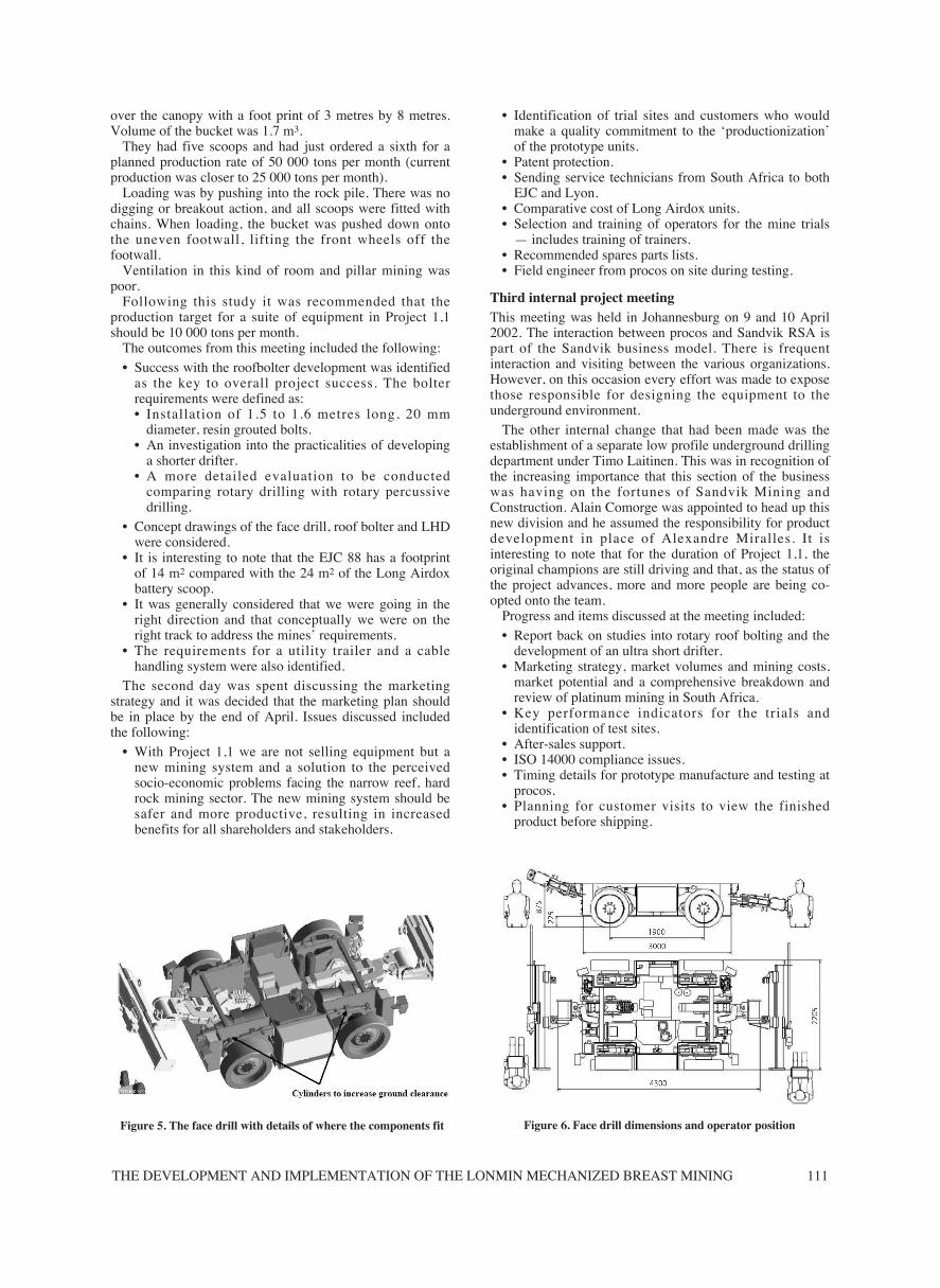
Figure 6. Face drill dimensions and operator positionFigure 5. The face drill with details of where the components fit
PLATINUM SURGES AHEAD112
• Feed back on equipment development status from theprocos.
The most significant change to the face drill had been theintroduction of hydraulic cylinders to increase groundclearance. Operating in the constraints of a narrow stopewith limited ground clearance it had been realized thatbridging of the equipment would be an ongoing problem.
At the end of a very busy week it had been agreed that:• The first trial would be held at Lonmin starting in
November 2002. The second trial would start aboutthree to four months later on an Anglo Platinum mine.
• For these trials the customer would pay for anyrequired mine infrastructure development, rental of theequipment and full operating and maintenance costs.Sandvik would be responsible for development of thetechnology, training, technical support and trialmanagement.
• It was essential to proceed with the development of theUltra Short Drifter for use on the roofbolter.
Fourth internal project meetingThe meeting was held in the EJC facility in Burlington on16 and 17 July 2002. The following formed the main thrustof the two days’ discussions.
• Detailed discussions on the what, where, when and howof the customer trials scheduled to start late in 2002.
• Detailed discussion on the hydrostatic drive system andthe CANbus interface with the engine. The hydraulicsystem should remain closed for substantially longerthan is the norm. Ideally it should only be opened oncea year. To achieve this objective the LHD has beenfitted with a long time filtration system and a waterextraction system.
• Sandvik RSA has developed a model of mining costand production performance. Based on this model itwas agreed that a production performance of 6 500 tonsper month was realistic. (Two shifts per day and 22days per month.)
• Technical and operator training of Sandvik RSApersonnel for equipment from Lyon and EJC was inhand.
• Performance KPIs for the trials now had to be agreedwith the customers.
• Sandvik also had to start allocating staff and resourcesfor the trials.
• Cable management was still an issue that had to beresolved by the local team.
• The ultra short drifter was on trial and looked as if itwould be ready by the end of 2002.
• Detailed discussion on the required support formDeutz.
• Extensive planning for customer visits to Lyon and EJCto see the prototype equipment.
The use of a hydrostatic drive system has been a majordeparture from EJC’s more traditional mechanical drivetrains. The MD of EJC, Lorne Massel, regards thisdevelopment as so crucial to the further development of hiscompany that he has arranged for all members of his staff toundergo a hydraulic training programme.
Customer visitsTowards the end of September 2002 Lonmin Platinumvisited EJC in Burlington and Lyon to view the finishedprototype equipment.
In all thoughts and consideration of Project 1,1 it must beremembered that the competition is not the other miningequipment manufacturers of this world but rather the waythings have been done for the last hundred years in thenarrow reef, hard rock mining industry.
Underground trialsUnderground trials have two main components: firstly isthe need to demonstrate that the equipment carries out thefunction that it was designed for and secondly that themining method employed is adequately productive.
With the XLP fleet of a face drill, roofbolter and LHDthere were a number of teething problems. This was mainlybecause Sandvik followed a different development route.The more normal approach is to develop a new machineand then conduct extensive trials in a controlledenvironment. In this case the new machines were rushedinto production environments and the result was anintegration of the equipment performance trial and themining method trial. The equipment performed withdifferent reliability.
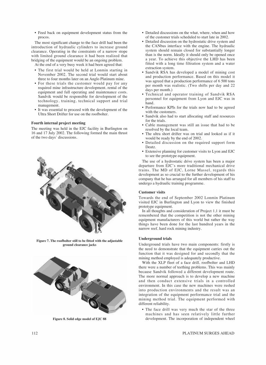
• The face drill was very much the star of the threemachines and has seen relatively little furtherdevelopment. The incorporation of independent wheelFigure 8. Solid edge model of EJC 88
Figure 7. The roofbolter still to be fitted with the adjustableground clearance jacks

THE DEVELOPMENT AND IMPLEMENTATION OF THE LONMIN MECHANIZED BREAST MINING 113
movement was a big success and these machines havenot experienced any problems of grounding the frameand the machine getting stuck.
• The roofbolter body was fine but the drilling feed hasseen a number of developments and is currently onabout the fourth generation. A bigbreak through wasthe successful introduction of the ultra-short drifter.This drifter was developed specifically for this bolterand is only 300mm in length compared to the morenormal dimension for a drifter of this power of 650mm.
• The loader was a different story. To operatesuccessfully it needed to push into the rock rather thanload up the front of the rock pile as in conventionalLHD operation. This put high tramming loads on thetyres and these were originally fitted with chains toprovide good traction. This solution was expensive andit was difficult to keep the chains tight and effective onthe small wheels. A second solution was to develop anew tyre that gave a reasonable life and good traction.It was also impossible to design a machine having arelatively small footprint with a conventionalmechanical drive transmission. Consequently, theloader was designed with a fully hydraulic poweringsystem with hydraulic wheel motors. The hydraulicsolution employed was not entirely successful andmuch effort was expended to get the hydraulics to workefficiently.
However, the choice of mining method and theapplication of the equipment were equally problematic,probably even more problematic than the equipment issues.This is probably because the technical issues can be seenand understood by equipment designers and solutionsquickly developed and tested. It is more difficult to bring
about major changes in the mining layout expeditiously andthis was coupled with a lack of mechanized miningexpertise that was available to design optimal layouts tomaximize the potential of the equipment.
• The low profile equipment had mainly been used in aroom and pillar mining layout and at an early stage itwas decided that the XLP fleet would be used in asimilar layout. Initial trials were using the equipmentfor room and pillar mining. Some of the early problemsencountered were related to blasting and a full advanceof the face was rarely achieved despite the input of‘blasting engineers’. Room and pillar mining has arelatively large number of faces and moving equipmentfrom one short face to another consumed a lot ofproduction time. The tipping points for the LHDs wereoften 60 to 100 metres away from the loading point andit was soon realized that the constricted mining heightlimited tramming speeds and equipment productivity,this was the biggest drawback of room and pillarmining. To make this even more complicated therewere three different XLP room and pillar mining trialsgoing on at the same time.
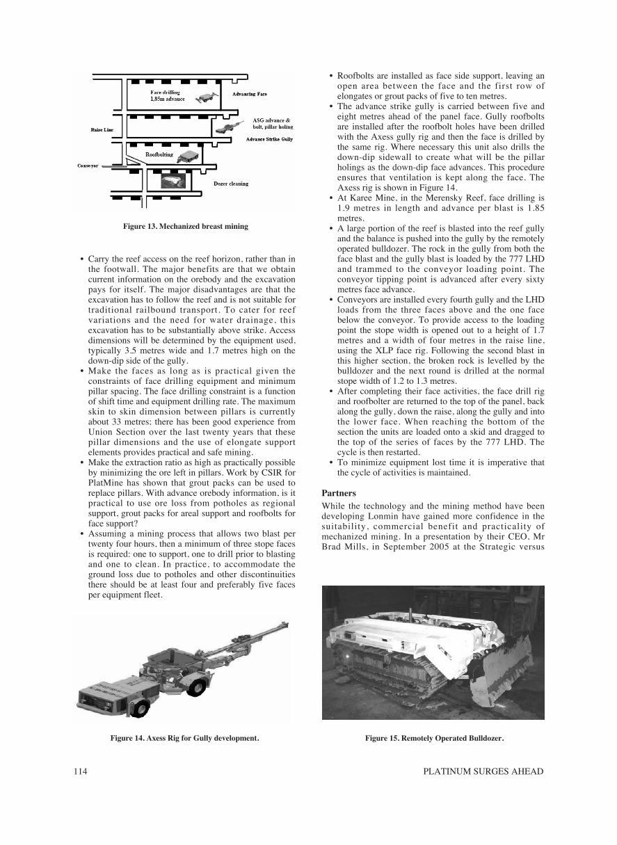
• Attention was then focused on a mining layout that hasa closer relationship to conventional mining. Longerpanels cleaning into a gully with rock movement in thegully with larger, more traditional LHDs, these wouldtip onto belt conveyors. Thus, the merits of on reefmining with no footwall development would berealized; extraction ratios would improve and themining sequence was more easily understood. Thelayout is called mechanized breast mining and is shownin Figure 13.
Mechanized breast mining is described as follows:
Figure 9. Roof bolter in a mock-up stope 1.1 metres high
Figure 10. Face drill carrying out test drilling
Figure 11. Partners proudly observe the proto type
Figure 12. The competition
PLATINUM SURGES AHEAD114
• Carry the reef access on the reef horizon, rather than inthe footwall. The major benefits are that we obtaincurrent information on the orebody and the excavationpays for itself. The major disadvantages are that theexcavation has to follow the reef and is not suitable fortraditional railbound transport. To cater for reefvariations and the need for water drainage, thisexcavation has to be substantially above strike. Accessdimensions will be determined by the equipment used,typically 3.5 metres wide and 1.7 metres high on thedown-dip side of the gully.
• Make the faces as long as is practical given theconstraints of face drilling equipment and minimumpillar spacing. The face drilling constraint is a functionof shift time and equipment drilling rate. The maximumskin to skin dimension between pillars is currentlyabout 33 metres; there has been good experience fromUnion Section over the last twenty years that thesepillar dimensions and the use of elongate supportelements provides practical and safe mining.
• Make the extraction ratio as high as practically possibleby minimizing the ore left in pillars. Work by CSIR forPlatMine has shown that grout packs can be used toreplace pillars. With advance orebody information, is itpractical to use ore loss from potholes as regionalsupport, grout packs for areal support and roofbolts forface support?
• Assuming a mining process that allows two blast pertwenty four hours, then a minimum of three stope facesis required: one to support, one to drill prior to blastingand one to clean. In practice, to accommodate theground loss due to potholes and other discontinuitiesthere should be at least four and preferably five facesper equipment fleet.
• Roofbolts are installed as face side support, leaving anopen area between the face and the first row ofelongates or grout packs of five to ten metres.
• The advance strike gully is carried between five andeight metres ahead of the panel face. Gully roofboltsare installed after the roofbolt holes have been drilledwith the Axess gully rig and then the face is drilled bythe same rig. Where necessary this unit also drills thedown-dip sidewall to create what will be the pillarholings as the down-dip face advances. This procedureensures that ventilation is kept along the face. TheAxess rig is shown in Figure 14.
• At Karee Mine, in the Merensky Reef, face drilling is1.9 metres in length and advance per blast is 1.85metres.
• A large portion of the reef is blasted into the reef gullyand the balance is pushed into the gully by the remotelyoperated bulldozer. The rock in the gully from both theface blast and the gully blast is loaded by the 777 LHDand trammed to the conveyor loading point. Theconveyor tipping point is advanced after every sixtymetres face advance.
• Conveyors are installed every fourth gully and the LHDloads from the three faces above and the one facebelow the conveyor. To provide access to the loadingpoint the stope width is opened out to a height of 1.7metres and a width of four metres in the raise line,using the XLP face rig. Following the second blast inthis higher section, the broken rock is levelled by thebulldozer and the next round is drilled at the normalstope width of 1.2 to 1.3 metres.
• After completing their face activities, the face drill rigand roofbolter are returned to the top of the panel, backalong the gully, down the raise, along the gully and intothe lower face. When reaching the bottom of thesection the units are loaded onto a skid and dragged tothe top of the series of faces by the 777 LHD. Thecycle is then restarted.
• To minimize equipment lost time it is imperative thatthe cycle of activities is maintained.
PartnersWhile the technology and the mining method have beendeveloping Lonmin have gained more confidence in thesuitability, commercial benefit and practicality ofmechanized mining. In a presentation by their CEO, MrBrad Mills, in September 2005 at the Strategic versus
Figure 13. Mechanized breast mining
Figure 14. Axess Rig for Gully development. Figure 15. Remotely Operated Bulldozer.
THE DEVELOPMENT AND IMPLEMENTATION OF THE LONMIN MECHANIZED BREAST MINING 115
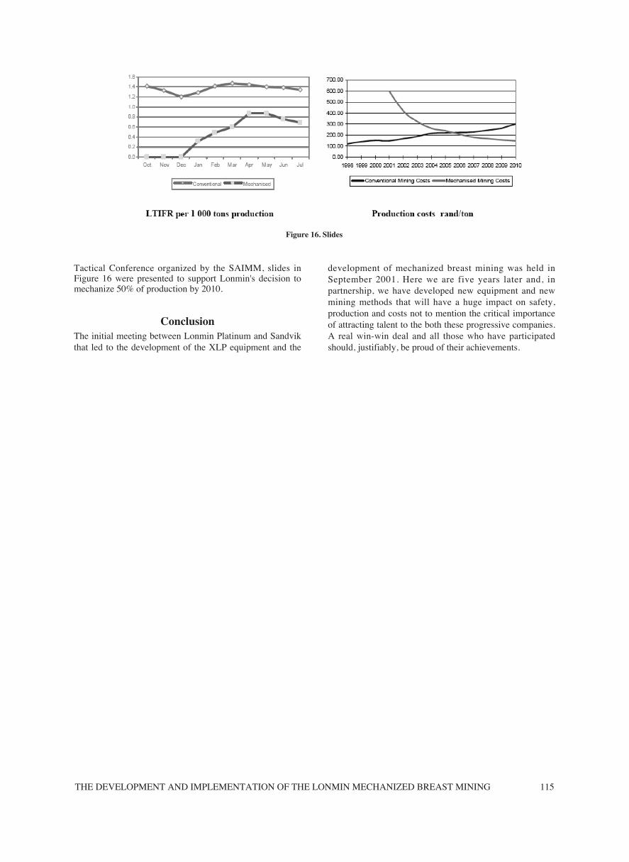
Tactical Conference organized by the SAIMM, slides inFigure 16 were presented to support Lonmin's decision tomechanize 50% of production by 2010.
ConclusionThe initial meeting between Lonmin Platinum and Sandvikthat led to the development of the XLP equipment and the
development of mechanized breast mining was held inSeptember 2001. Here we are five years later and, inpartnership, we have developed new equipment and newmining methods that will have a huge impact on safety,production and costs not to mention the critical importanceof attracting talent to the both these progressive companies.A real win-win deal and all those who have participatedshould, justifiably, be proud of their achievements.
Figure 16. Slides

PLATINUM SURGES AHEAD116