Embed Size (px)
Citation preview

-1-
The Development of 300kW Class High EfficiencyMicro Gas Turbine “RGT3R”
Ryousuke Shibata 1
Yoshio Nakayama 1
Shutaro Machiya 2
Kazuyuki Kobayashi 1
1 Engineering & Technology Center, Design & Development Group, Gas Turbine Development TeamNiigata Power Systems Co., Ltd.
5-2756-3 Higasi-kou, Seirou-machi, Kita-kambara-gun, Niigata pref. 957-0101, JAPANPhone: +81-25-256-3515, FAX: +81-25-256-3532, E-mail: [email protected]
2 Graduate School of Mechanical Engineering, Nagoya UniversityFuro-chou, Chikusa-ku, Nagoya City, Aichi pref. 464-8603, JAPAN
Phone: +81-52-789-4672, FAX: +81-52-789-3111
IGTC2003Tokyo TS-115
Copyright © 2003 by GTSJManuscript Received on March 31, 2003
ABSTRACTNiigata Power Systems Co., Ltd. has developed a continuous
use 300-kW electric output power Recuperated Cycle Gas TurbineRGT3R with a liquid fuel Dry Low Emission (DLE) combustorfrom 2000 to 2003. The thermal efficiency specification at thegenerator end of the RGT3R is 32.5%. The latest prototype hasbeen confirmed to achieve a thermal efficiency of 31.4% or higherand NOx emissions of 20 ppm or less in terms of 16%O2conversion at load rates between 50% and full load.
The first commercial production is expected to start in thebeginning of April 2004 when all the durability testing arecompleted.
INTRODUCTIONFor the past few years, a number of manufactures have
developed a Micro Gas Turbine (MGT) system or its peripheralapplications. However, an assessment of these devices in terms oftotal life cycle cost, including the sum of initial cost, constructioncosts, operating costs, and maintenance costs, shows that a currentMGT requires extremely high costs per unit output due to theirlimited power output. Cost breakdowns for 30-kW and 300-kWMGT are shown in Fig. 1. Although the difference in the outputs ofthese two turbines is significantly large, the difference in the initialconstruction costs, including electrical work, is small as shown inFig. 1. Therefore, the MGT has not widely used due to thisdisadvantage.
In order to minimize the total life cycle cost per unit output, an
appropriate output had to be determined. The result of this study istabulated in Table 1, such as the target electric output and thetargeted thermal efficiency at the generator end for two cases, asimple cycle and recuperated gas turbines. Based on this result, twotypes of gas turbines were developed, which were the RGT3C, a300-kW-class simple cycle gas turbine, and the RGT3R, arecuperated cycle gas turbine.
In this paper, the development of the RGT3R recuperated cyclegas turbine is described, focusing on its history, features, and theperformance on the latest testing result.
Table.1 Design Specification of Niigata 300kW Class MGT
Specifications are expected to be under the ISO condition.T0=15 , P0=1013hPa, Inlet & Exhaust Pressure drops=0kPa
Engine Name RGT3R RGT3CAir Flow Rate 2.5kg/s ←Pressure Ratio 4.02 ←Rotation Speed 36943 min-1 ←Electric Output Power 300kWe 360kWeThermal Efficiency @ Generator End
32.5% 16.3%
Remarks RecuperatedCycle
SimpleCycle
Fig.1 Initial Cost Comparison between 30kW and 300kW Recuperated MGT(300kW MGT GENE-SET Price indicates an example of the first testing GENE-SET price.)
Proceedings of the International Gas Turbine Congress 2003 TokyoNovember 2-7, 2003
-2-
OVERVIEW OF THE DEVELOPMENTSeveral important issues in the development of our MGT
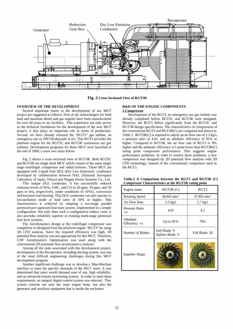
project are suggested as follows. First of all, turbochargers for bothland and maritime diesel and gas engines have been manufacturedfor over 40 years in our facilities. This experience not only servesas the technical foundation for the development of the new MGTproject; it also plays an important role in terms of production.Second, we have already released the “RGT3” gas turbine, anemergency-use in 1997 (Kobayashi et al.). This RGT3 provides theplatform engine for the RGT3C and RGT3R continuous use gasturbines. Development programs for these MGT were launched atthe end of 2000, a mere two years before.
Fig. 2 shows a cross sectional view of RGT3R. Both RGT3Cand RGT3R are single shaft MGT which consist of the same singlestage centrifugal compressor and radial turbines. These MGT areequipped with Liquid Fuel DLE (Dry Low Emission) combustordeveloped by collaboration between NAL (National AerospaceLaboratory of Japan, Tokyo) and Niigata Power Systems Co., Ltd.
This unique DLE combustor, it has successfully reducedemission levels of NOx, UHC, and CO to 20 ppm, 50 ppm, and 50ppm or less, respectively, under conditions of 16%O2 conversionand kerosene fuel burning. This DLE combustor can also operate inlow-pollution mode at load rates of 50% or higher. Thischaracteristics is achieved by adopting a two-stage parallelpremixed pre-vaporized lean burn system, implemented in a simpleconfiguration. Not only does such a configuration reduce costs; italso provides reliability superior to existing multi-stage premixedlean burn systems.
The Aerodynamics design at the centrifugal compressor wascompletely re-designed from the platform engine “RGT3” by using3D CFD analysis. Since the required efficiency was high, 2Dpotential flow analysis was not appropriate for this MGT. Therefore,CDF Aerodynamics Optimization was used along with theconventional 2D potential flow aerodynamics analysis.
Among all the tasks associated with this development project,development of the Recuperator, including ducting system, was oneof the most difficult engineering challenges during this MGTdevelopment program.
Another significant challenge was to develop a Man-Machineinterface to meet the specific demands of the MGT users. It wasdetermined that users would demand ease of use, high reliability,and an advanced remote monitoring system. In order to meet theserequirements, an integral digital control system was selected. Thissystem controls not only the main engine body, but also thegenerator and auxiliary equipment that is inside the enclosure.
R&D OF THE ENGINE COMPONENTS1.Compressor
Development of the RGT3, an emergency-use gas turbine wasalready completed before RGT3C and RGT3R were designed.However, the RGT3 differs significantly from the RGT3C andRGT3R design specification. The characteristics of compressors ofthe conventional RGT3 and RGT3R(C) are compared and shown inTable 2. RGT3R(C) is required to satisfy an air flow rate of 2.5 kg/s,a pressure ratio of 4.02, and an adiabatic efficiency of 81% orhigher. Compared to RGT3R, the air flow rate of RGT3 is 8%higher and the adiabatic efficiency is 5 point lower than RGT3R(C)rating point compressor performance. This suggests engineperformance problems. In order to resolve these problems, a newcompressor was designed by 2D potential flow analysis with 3DCFD technology, instead of the conventional compressor used inthe RGT3.
Fig. 2 Cross Sectional View of RGT3R
Table.2 A Comparison between the RGT3 and RGT3R (C)Compressor Characteristics at the RGT3R rating point
Engine name RGT3R (C) RGT3
Rotating Speed 36,943 min-1 37,005 min-1
Air Flow Rate 2.5 kg/s 2.7 kg/s
Pressure Ratio t-t 4.02 4.2
AdiabaticEfficiency t-t Up to 81% 76%
Number of BladesFull Blade: 9Splitter Blade: 9 Full Blade: 20
Impeller Shape
GeneratorReductionGear Box
RecuperatorDry Low EmissionCombustor

-3-
CFD analysis of the relative Mach number distribution at theimpeller inducer tip area is shown in Fig. 3. The left is the CFDresult of an initial impeller design based on conventional 2Dpotential flow design. This indicates that the Mach number is largeat the top end of the blade. In contrast, the right figure is the CFDresults for an impeller with optimized inducer inlet angle usingCFD. This represents that the relative Mach number is lower at thesame point. The difference arises because of the viscosity of theboundary layer that develops on an impeller shroud. The 2Dpotential flow analysis can not handle the effects of the viscosity. Inorder to overcome this issue, 3D CFD optimization was introduced.In summary, by utilizing the 3D CFD optimization, the relativeMach number at the impeller inducer tip area was reduced from1.14 of the initial shape to 1.08.
Velocity vector distribution on the suction side of the impellersplitter blade was estimated by CFD as shown in Fig. 4. The leftfigure, which is for the impeller initial shape based on 2D potentialflow design, indicates the adverse flow circulation in the vicinity ofa shroud wall surface. Such adverse flow circulation is likely toencourage the development of a boundary layer, which results inincreased blockage and degrading of impeller performance. Incontrast, an optimal curvature of the shroud wall surface by CFD isshown in the right and the adverse flow is eliminated as shown inthe left figure.
Performance test results of a compressor optimized with CFDis represented in Fig. 5. The air flow rates and pressure ratio almostmeet the design specification of RGT3R as shown in Fig. 5. On theother hand, adiabatic efficiency still does not satisfy the designspecification, falling 1 point short. Since this causes a 0.5%shortfall in terms of engine thermal efficiency, this parameter needsto be improved before the first commercial production starts.
2. Turbine Wheel & Rotor DynamicsFor both RGT3C and RGT3R, high-performance turbine
wheels of RGT3 were used because of the extensive past results onthese turbine wheels. Since both simple cycle and recuperated cyclerequire different turbine expansion ratios due to the recuperatorpressure drops even at the same cycle pressure ratio, two types ofturbine nozzles were designed for both cycles. The rotor assemblyof RGT3R(C) with a power output coupling is shown in Fig. 6. Theturbine wheel is made of nickel-base heat-resistant super alloycasting. The Rotor assembly is supported by tilting pad journalbearings in order to minimize a maintenance interval. Themechanical losses of RGT3R(C) are 40% greater than that of theRGT3, which used a ball-and-roller bearing. Reducing theseexcessive losses remains to be resolved in the future.
Fig. 6 RGT3R (C) Rotor Assembly
Fig. 3 Relative Mach Number distribution at the impellerinducer tip area.
Fig. 5 Test Results of CFD Optimized Compressor Performance
Fig. 4 Relative velocity vector distribution comparison at thesuction side of the impeller splitter blade.
Basic Design CFD Optimized
AdverseFlow Area
Basic Design CFD Optimized
M=1.14 M=1.08

-4-
The predicted and measured unbalance response at the rotoroutput-coupling end is shown in Fig. 7. This figure indicates thatthere is no resonance point near the rating rotating speed and thatthe amplitude is very small. Therefore, the combination of the rotorand tilting pad journal bearing offers very good balance betweenbearing attenuation and stiffness as well as good stability across awide range of velocities. If a direct-drive high-speed generator witha wide range of operating speeds is adopted in the future, thischaracteristic will be a significant advantage.
3. Casing Structural Analysis and Material DevelopmentRecuperated Cycle was chosen for the RGT3R to reduce the
fuel consumption. Since the temperature of the combustion airdischarged from the Recuperator becomes much higher thanSimple Cycle case, the temperature gradient in the turbine casing ofthe Recuperated Cycle becomes much larger than that of SimpleCycle. This high temperature gradient induces strong thermal stress.Usually such a kind of high thermal stress causes the short-termfatigue of the turbine casing. In order to achieve sufficient fatiguelife, new material called “PNX-TES3” was developed and used forRGT3R, instead of conventional stainless casting steel, SCH11.The PNX-TES3 was developed by collaboration between NiigataPower Systems Co., Ltd. and a casting manufacturer.
FEM analysis for the RGT3R is shown in Fig. 8. Evaluation ofa low cycle life was carried out in accordance with ASME N-47boiler and pressure vessel design code as shown in Fig. 9. Theupper figure is the low cycle fatigue life of SCH11, indicating thatthe fatigue life under daily start-and-stop operation is only 8.3 years.The lower figure shows that in the case of PNX-TES3, low cyclefatigue life can be ensured for 25 years or longer. This is due to thelow thermal expansion and high thermal conductivitycharacteristics of PNX-TES3, which reduce thermal stress levelsand increase the high temperature fatigue strength of PNX-TES3.
Fig.8 A FEM analysis example of the RGT3R Turbine Casing(SCH11)
4. Development of the Recuperator, & Ducting systemThe development of the Recuperator, including ducting system,
was one of the most difficult engineering challenges during thisMGT development program. The recuperated cycle is a well-understood area of thermodynamics. But this cycle had not beenapplied on the MGT because of inadequate heat exchange capacityof recuperator per unit volume and insufficient recuperatordurability. Today, recuperator technology has made remarkablestrides, thanks to sustained efforts by heat transfer engineers,materials scientists and technical staff at various companies. Thesuccess of the RGT3R development project owes much to jointefforts with a recuperator manufacturer.
At the start of this project, evaluation of the durability on therecuperator and a method to support the ducting system andrecuperator are focused as a development goal.
Successful development of a high-performance recuperatorinvolved finding a way to reduce the thermal stress of a heat-exchanging core and attached structural members of the recuperator.Moreover, since reactions resulting from pressure within therecuperator ducting system often resulted in unexpected damage onthe recuperator. A design in which the reaction of the ductingsystem was balanced needed to be overcome. Furthermore, sincethe heat-exchanging core of the recuperator was an integral part bymeans of special heat-resistant brazing, this could not be repairedby any means, which made the design even more difficult. Thus,investigations including highly accurate low cycle fatigue lifepredictions were needed before manufacturing of an actualrecuperator began. In order to overcome these design specifications,3D CAD with FEM structure analysis system played a central rolein studies of ducting configurations. It also facilitated effectivecommunications with the manufacturer of the recuperator.
Fig.7 Comparison between Unbalance Response analysisPrediction and Test Data at the Rotor Output Coupling end.
Fig.9 Low Cycle Fatigue Life of the RGT3R Turbine CasingEvaluated in accordance with ASME N-47 code(Upper: SCH11 / Lower: PNX-TES3 @400�)
MaximumAlternatingStrain: 0.34% @414
1/20 Nf
1/2 �
3000N/360=8.3years
0.34%�
SCH11@400�
1/20 Nf
1/2 �
10000N/360=27.8years
0.21%�
PNX-TES3@400�
0 10000 20000 30000 40000 50000Rotating Speed [min-1]
2468
1012141618
0
Rating Speed
Amplitude p-p [ m]
Predicted
Measured
-5-
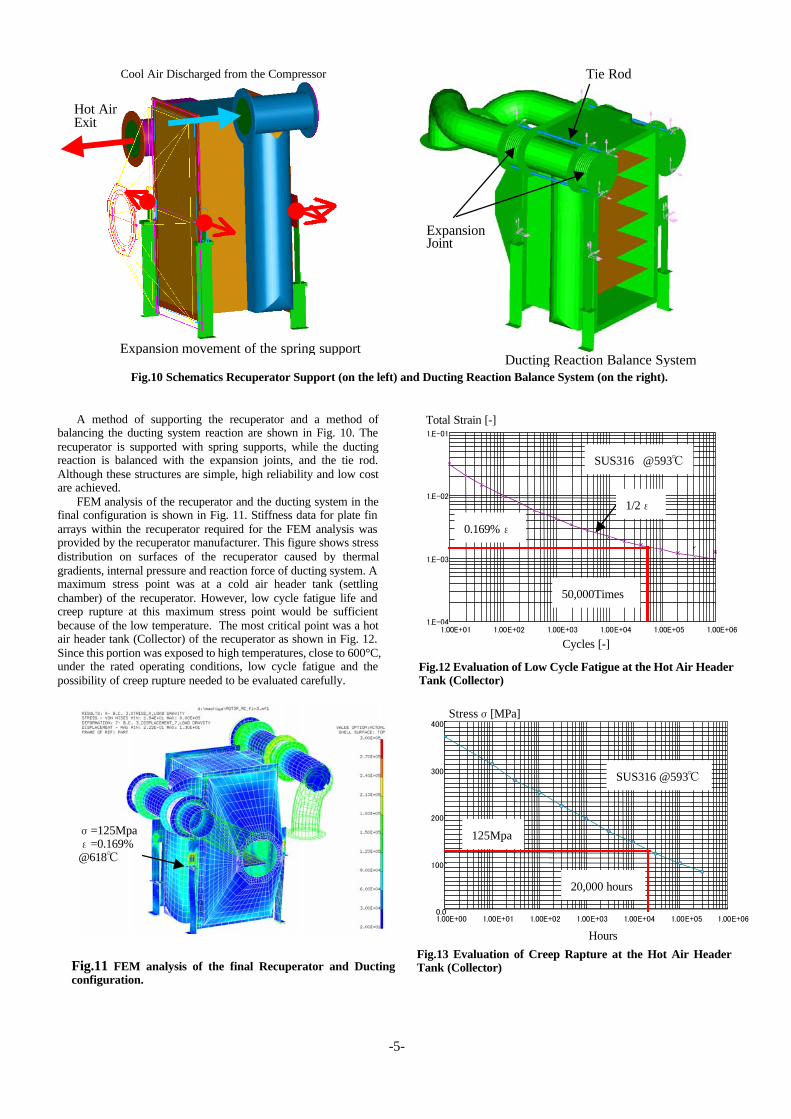
A method of supporting the recuperator and a method ofbalancing the ducting system reaction are shown in Fig. 10. Therecuperator is supported with spring supports, while the ductingreaction is balanced with the expansion joints, and the tie rod.Although these structures are simple, high reliability and low costare achieved.
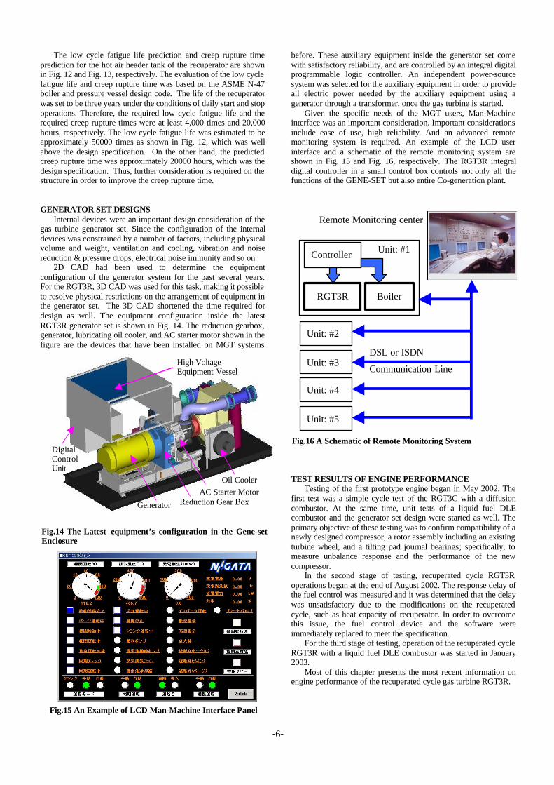
FEM analysis of the recuperator and the ducting system in thefinal configuration is shown in Fig. 11. Stiffness data for plate finarrays within the recuperator required for the FEM analysis wasprovided by the recuperator manufacturer. This figure shows stressdistribution on surfaces of the recuperator caused by thermalgradients, internal pressure and reaction force of ducting system. Amaximum stress point was at a cold air header tank (settlingchamber) of the recuperator. However, low cycle fatigue life andcreep rupture at this maximum stress point would be sufficientbecause of the low temperature. The most critical point was a hotair header tank (Collector) of the recuperator as shown in Fig. 12.Since this portion was exposed to high temperatures, close to 600°C,under the rated operating conditions, low cycle fatigue and thepossibility of creep rupture needed to be evaluated carefully.
Fig.12 Evaluation of Low Cycle Fatigue at the Hot Air HeaderTank (Collector)
Fig.10 Schematics Recuperator Support (on the left) and Ducting Reaction Balance System (on the right).
Fig.11 FEM analysis of the final Recuperator and Ductingconfiguration.
Fig.13 Evaluation of Creep Rapture at the Hot Air HeaderTank (Collector)
Ducting Reaction Balance System
ExpansionJoint
Tie Rod
Expansion movement of the spring support
Hot AirExit
Cool Air Discharged from the Compressor
=125Mpa=0.169%
@618
Total Strain [-]
Cycles [-]
SUS316 @593
0.169%
50,000Times
1/2
Stress [MPa]
125Mpa
SUS316 @593
20,000 hours
Hours
-6-
The low cycle fatigue life prediction and creep rupture timeprediction for the hot air header tank of the recuperator are shownin Fig. 12 and Fig. 13, respectively. The evaluation of the low cyclefatigue life and creep rupture time was based on the ASME N-47boiler and pressure vessel design code. The life of the recuperatorwas set to be three years under the conditions of daily start and stopoperations. Therefore, the required low cycle fatigue life and therequired creep rupture times were at least 4,000 times and 20,000hours, respectively. The low cycle fatigue life was estimated to beapproximately 50000 times as shown in Fig. 12, which was wellabove the design specification. On the other hand, the predictedcreep rupture time was approximately 20000 hours, which was thedesign specification. Thus, further consideration is required on thestructure in order to improve the creep rupture time.
GENERATOR SET DESIGNSInternal devices were an important design consideration of the
gas turbine generator set. Since the configuration of the internaldevices was constrained by a number of factors, including physicalvolume and weight, ventilation and cooling, vibration and noisereduction & pressure drops, electrical noise immunity and so on.
2D CAD had been used to determine the equipmentconfiguration of the generator system for the past several years.For the RGT3R, 3D CAD was used for this task, making it possibleto resolve physical restrictions on the arrangement of equipment inthe generator set. The 3D CAD shortened the time required fordesign as well. The equipment configuration inside the latestRGT3R generator set is shown in Fig. 14. The reduction gearbox,generator, lubricating oil cooler, and AC starter motor shown in thefigure are the devices that have been installed on MGT systems
before. These auxiliary equipment inside the generator set comewith satisfactory reliability, and are controlled by an integral digitalprogrammable logic controller. An independent power-sourcesystem was selected for the auxiliary equipment in order to provideall electric power needed by the auxiliary equipment using agenerator through a transformer, once the gas turbine is started.
Given the specific needs of the MGT users, Man-Machineinterface was an important consideration. Important considerationsinclude ease of use, high reliability. And an advanced remotemonitoring system is required. An example of the LCD userinterface and a schematic of the remote monitoring system areshown in Fig. 15 and Fig. 16, respectively. The RGT3R integraldigital controller in a small control box controls not only all thefunctions of the GENE-SET but also entire Co-generation plant.
TEST RESULTS OF ENGINE PERFORMANCETesting of the first prototype engine began in May 2002. The
first test was a simple cycle test of the RGT3C with a diffusioncombustor. At the same time, unit tests of a liquid fuel DLEcombustor and the generator set design were started as well. Theprimary objective of these testing was to confirm compatibility of anewly designed compressor, a rotor assembly including an existingturbine wheel, and a tilting pad journal bearings; specifically, tomeasure unbalance response and the performance of the newcompressor.
In the second stage of testing, recuperated cycle RGT3Roperations began at the end of August 2002. The response delay ofthe fuel control was measured and it was determined that the delaywas unsatisfactory due to the modifications on the recuperatedcycle, such as heat capacity of recuperator. In order to overcomethis issue, the fuel control device and the software wereimmediately replaced to meet the specification.
For the third stage of testing, operation of the recuperated cycleRGT3R with a liquid fuel DLE combustor was started in January2003.
Most of this chapter presents the most recent information onengine performance of the recuperated cycle gas turbine RGT3R.
Fig.16 A Schematic of Remote Monitoring System
Fig.15 An Example of LCD Man-Machine Interface Panel
Fig.14 The Latest equipment’s configuration in the Gene-setEnclosure
Generator Reduction Gear BoxAC Starter Motor
Oil Cooler
DigitalControlUnit
High VoltageEquipment Vessel
RGT3R Boiler
Controller Unit: #1
Unit: #2
Unit: #3
Unit: #4
Unit: #5
Remote Monitoring center
DSL or ISDN
Communication Line
-7-
Fig.17 Prototype RGT3R equipped with Dry Low EmissionCombustor
The RGT3R prototype equipped with a liquid fuel DLEcombustor is shown in Fig. 17. Fuel metered by an electricgovernor is distributed to a pilot and main burners. A shut-off valvefor the main burner fuel is opened at a staging point, whichcorresponds to a load rate of approximately 50%. At the same time,a servo valve controls the pilot burner fuel ratio. Duringpreliminary testing, instead of a servo valve, a manual needle valveis attached to the pilot fuel line as shown in Fig. 17. The flow rate ofthe pilot and main fuel were measured with precise volume flowmeters in the testing.
Except for the DLE fuel control hardware, the equipment of thetesting were those to be used for the commercial generator setproduct. These equipment include the recuperator and ductingsystem, the newly designed reduction gear box, a case-coupledgenerator, integral digital control unit and high voltage controlconsole. The prototype RGT3R engine as part of a complete systemis shown in Fig. 18.
Fig.18 Prototype of RGT3R Engine Test Rig (Completed)
Fig.19. Thermal Efficiency of prototype RGT3R
Described in this paper, numerous component tests wereperformed, such as the metal sealing test of the recuperator ducting.Moreover, since an extremely high temperature air for combustionwas required for the DLE combustor development, a DLEcombustor test rig was significantly modified (the changes were sosignificant that the associated work equaled the work requiredbuilding a new test rig). The compressor underwent similarmodifications. Several types of diffusers were tested to assess theirperformance over a very short period as well.
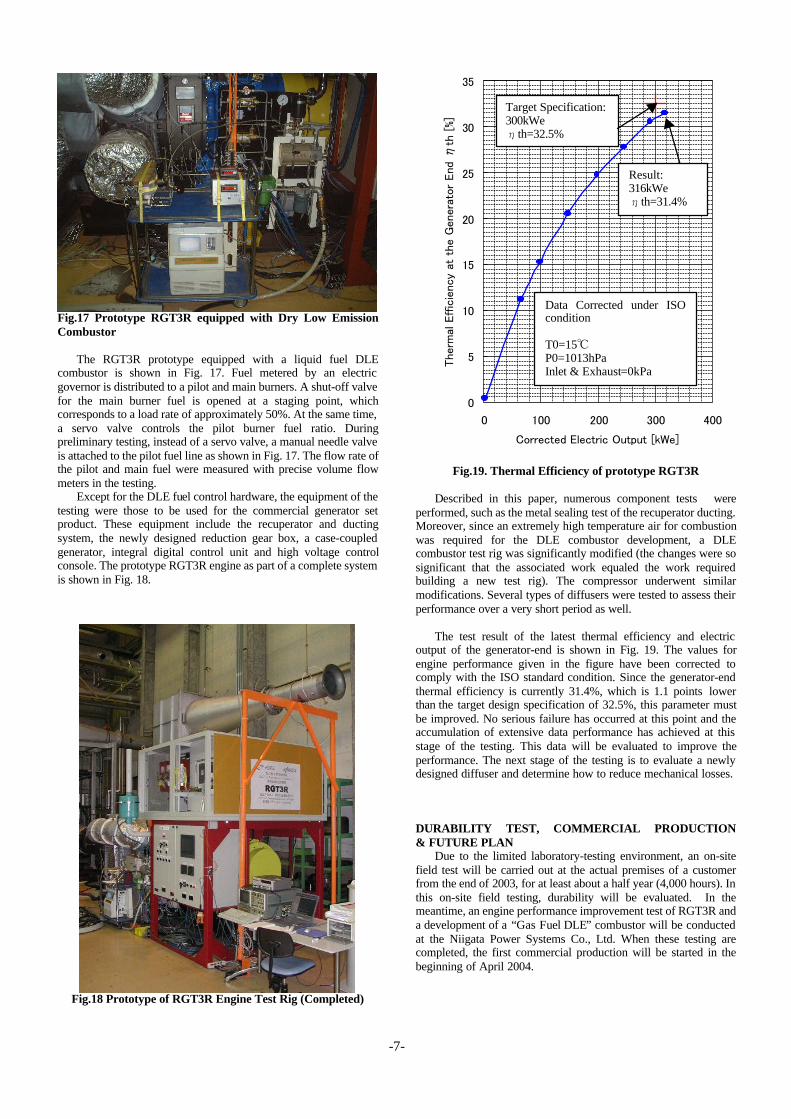
The test result of the latest thermal efficiency and electricoutput of the generator-end is shown in Fig. 19. The values forengine performance given in the figure have been corrected tocomply with the ISO standard condition. Since the generator-endthermal efficiency is currently 31.4%, which is 1.1 points lowerthan the target design specification of 32.5%, this parameter mustbe improved. No serious failure has occurred at this point and theaccumulation of extensive data performance has achieved at thisstage of the testing. This data will be evaluated to improve theperformance. The next stage of the testing is to evaluate a newlydesigned diffuser and determine how to reduce mechanical losses.
DURABILITY TEST, COMMERCIAL PRODUCTION& FUTURE PLAN
Due to the limited laboratory-testing environment, an on-sitefield test will be carried out at the actual premises of a customerfrom the end of 2003, for at least about a half year (4,000 hours). Inthis on-site field testing, durability will be evaluated. In themeantime, an engine performance improvement test of RGT3R anda development of a “Gas Fuel DLE” combustor will be conductedat the Niigata Power Systems Co., Ltd. When these testing arecompleted, the first commercial production will be started in thebeginning of April 2004.
Result:316kWe
th=31.4%
Target Specification:300kWe
th=32.5%
Data Corrected under ISOcondition
T0=15P0=1013hPaInlet & Exhaust=0kPa
-8-
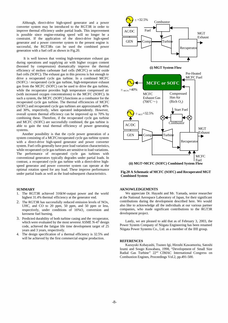
Although, direct-drive high-speed generator and a powerconverter system may be introduced to the RGT3R in order toimprove thermal efficiency under partial loads. This improvementis possible since engine-rotating speed will no longer be aconstraint. If the application of the direct-drive high-speedgenerator and a power converter system to the present engine issuccessful, the RGT3Rs can be used the combined powergeneration with a fuel cell as shown in Fig.20.
It is well known that venting high-temperature exhaust gasduring operations and supplying air with higher oxygen content(boosted by compression) dramatically improve the thermalefficiency of molten carbonate fuel cells (MCFC) or solid oxidefuel cells (SOFC). The exhaust gas in this process is hot enough todrive a recuperated cycle gas turbine. In a combined MCFC(SOFC) / recuperated cycle gas turbine, high-temperature exhaustgas from the MCFC (SOFC) can be used to drive the gas turbine,while the recuperator provides high temperature compressed air(with increased oxygen concentrations) to the MCFC (SOFC). Insuch a system, the MCFC (SOFC) functions as a combustor for therecuperated cycle gas turbine. The thermal efficiencies of MCFC(SOFC) and recuperated cycle gas turbines are approximately 40%and 30%, respectively, when operated independently. However,overall system thermal efficiency can be improved up to 70% bycombining these. Therefore, if the recuperated cycle gas turbineand MCFC (SOFC) are successfully combined, the gas turbine isable to gain the total thermal efficiency of power generatingsystems.
Another possibility is that the cycle power generation of asystem consisting of a MCFC/recuperated cycle gas turbine systemwith a direct-drive high-speed generator and power convertersystem. Fuel cells generally have poor load variation characteristics,while recuperated cycle gas turbines are sensitive to load variations.The performance of recuperated cycle gas turbines withconventional generators typically degrades under partial loads. Incontrast, a recuperated cycle gas turbine with a direct-drive high-speed generator and power converter system can operate at theoptimal rotation speed for any load. These improve performanceunder partial loads as well as the load-subsequent characteristics.
SUMMARY1. The RGT3R achieved 316kW-output power and the world
highest 31.4% thermal efficiency at the generator end.2. The RGT3R has successfully reduced emission levels of NOx,
UHC, and CO to 20 ppm, 50 ppm, and 50 ppm or less,respectively, under conditions of 16%O2 conversion andkerosene fuel burning.
3. Predicted durability of both turbine casing and the recuperator,which were evaluated by the most severest ASME N-47 designcode, achieved the fatigue life time development target of 25years and 3 years, respectively.
4. The design specification of a thermal efficiency is 32.5% andwill be achieved by the first commercial engine production.
AKNOWLEDGEMENTSWe appreciate Dr. Hayashi and Mr. Yamada, senior researcher
at the National Aerospace Laboratory of Japan, for their significantcontributions during the development described here. We wouldalso like to acknowledge all the individuals at our various partnercompanies, who made significant contributions to the RGT3Rdevelopment project.
Lastly, we are pleased to add that as of February 3, 2003, thePower System Company of Niigata Engineering has been renamedNiigata Power Systems Co., Ltd. as a member of the IHI group.
REFERENCESKazuyuki Kobayashi, Tsuneo Igi, Hiroshi Kawamorita, Satoshi
Izumi and Sougo Kuwabara, 1998, “Development of Small SizeRadial Gas Turbine” 22nd CIMAC International Congress onCombustion Engines, Proceedings Vol.2, pp.491-500.
(i) MGT System Flow
(ii) MGT+MCFC (SOFC) Combined System Flow
Fig.20 A Schematic of MCFC (SOFC) and Recuperated MGTCombined System
GEN Comp. Turbine
Recuperator
Combustor
AC/DC
=32.5%
FuelMGTExhaust
MCFC=40%
GEN Comp. Turbine
Recuperator
CombustorAC/DC
MGT=32.5%Start Fuel
MCFCFuel
CompressedHot-Air(Rich O2)
Pre-HeatedMCFC Fuel
MCFCExhaust Gas(700 )
MGTExhaust
MCFC or SOFC