Embed Size (px)
Citation preview
The Diffraction Grating
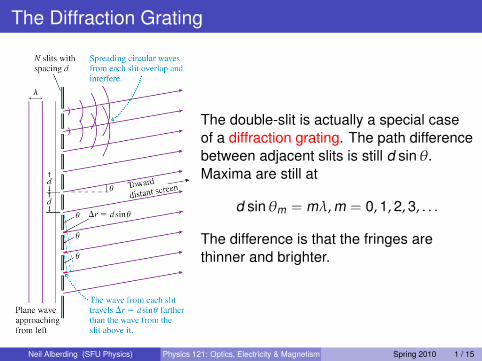
The double-slit is actually a special caseof a diffraction grating. The path differencebetween adjacent slits is still d sinθ.Maxima are still at
d sinθm = mλ,m = 0,1,2,3, . . .
The difference is that the fringes arethinner and brighter.
Neil Alberding (SFU Physics) Physics 121: Optics, Electricity & Magnetism Spring 2010 1 / 15

The Diffraction Grating
Why are the fringes thinner and brighter?The brightness comes from the fact that constructive interferenceis now happening from more sources:
Imax = N2I1
One way to think about the narrowness is conservation of energy.If the bright fringes will be so much brighter (gain a square in theformula above) then they must be narrower too.
Neil Alberding (SFU Physics) Physics 121: Optics, Electricity & Magnetism Spring 2010 2 / 15

The Diffraction Grating
Why are the fringes thinner and brighter?Another way to think of it is to look at the geometry again. Imagine weintroduce a small phase difference between adjacent slits, say 1.1λinstead of 1λ
With two adjacent slits, this does not affect the intensity very muchNow imagine the interference of 2 slits which are separated by 5d(non-adjacent slits). 5 × 1.1λ = 5.5λ. Now these two slits aredestructively interfering!Total width of the central max is (for large number of slits)
2θmin =2λNd
Measuring θmin can be an excellent way to determine an unknownλ
Neil Alberding (SFU Physics) Physics 121: Optics, Electricity & Magnetism Spring 2010 3 / 15

Reflection Gratings
Most common gratings are actuallyreflection gratings rather thantransmission gratings.A mirror with thousands of narrowparallel grooves makes a gratingwhich reflects light instead oftransmitting it, but the math is thesame.A CD is an excellent example.
Neil Alberding (SFU Physics) Physics 121: Optics, Electricity & Magnetism Spring 2010 4 / 15

Compact Discs
A CD is a reflective surface coveredin small bumps/pits. Each second ofmusic requires ∼ 106 bumps.From above there are “pits” in analuminum layer, but CD is read frombelow, so “bumps” are seen.A CD player shines a laser on thebumps in a spiral track and detectsthe reflected laser beam.The intensity of the reflected beamchanges as the bumps and landspass by. Height of a bump is aboutλ/4, making a path difference of λ/2and a phase change of π.
Neil Alberding (SFU Physics) Physics 121: Optics, Electricity & Magnetism Spring 2010 5 / 15

Compact Discs Tracking System
A diffraction grating is used.The central maximum readsthe bumps while the1st-order maxima are usedas tracking beams (theyshould not fluctuate).
Neil Alberding (SFU Physics) Physics 121: Optics, Electricity & Magnetism Spring 2010 6 / 15

Single Slit Diffraction
It is rather strange to talkabout thousands of slits beforetalking about 1. However,thousands are actually a littleeasier.A single slit diffraction patterninvolves a wide centralmaximum flanked by weakersecondary maxima and darkfringes.It would appear that we haveonly one light source in thiscase, so how do weunderstand the interference?We have to go back toHuygen’s principle.
Neil Alberding (SFU Physics) Physics 121: Optics, Electricity & Magnetism Spring 2010 7 / 15

Single Slit Diffraction
A wave front passes through a narrowslit (width a). Note that narrow isimportant.Each point on the wave-front emits aspherical waveOne slit becomes the source of manyinterfering wavelets.A single slit creates a diffractionpattern on the screen.
Neil Alberding (SFU Physics) Physics 121: Optics, Electricity & Magnetism Spring 2010 8 / 15

Why the Wide Central Maximum?
Wavelets from any part of the slithave to travel approximately the samedistance to reach the center of thescreen.A set of in-phase wavelets thereforeproduce constructive interference atthe center of the screen.
Neil Alberding (SFU Physics) Physics 121: Optics, Electricity & Magnetism Spring 2010 9 / 15

Why the Dark Bands?
Consider the path-lengths well awayfrom the centre axisFor any wavelet it is possible to find apartner which is a/2 away.If the path difference betweenpartners happens to be λ/2 then thispair will create total destructiveintereference. A dark band will becreated.For any given wavelength there willbe an angle for which this condition istrue! There will always be darkbands, as long as a is greater than λand the slit is narrow.
Neil Alberding (SFU Physics) Physics 121: Optics, Electricity & Magnetism Spring 2010 10 / 15

The Mathematics of the Dark Bands
The path difference between 1 and 2is
∆r12 =a2
sinθ1 =λ2
What about the other angles fordestructive interference? The generalformula becomes
a sinθp = pλ,p = 1,2,3, . . .
The small angle approximationmeans we can write
θp = pλa,p = 1,2,3, . . .
But if a is small, the small angleapproximation is not valid.
Neil Alberding (SFU Physics) Physics 121: Optics, Electricity & Magnetism Spring 2010 11 / 15

The Width of the Bands
It can be useful to express the fringeposition in distance rather than angle.The position on the screen is given byyp = L tanθp. This leads to
yp =pλL
a,p = 1,2,3, . . .
The width of the central maximum is giveby twice the distance to the first darkfringe
w =2λL
aIt is important to note that: 1) the widthgrows if the screen is farther away 2) Athinner slit makes a wider centralmaximum.
Neil Alberding (SFU Physics) Physics 121: Optics, Electricity & Magnetism Spring 2010 12 / 15

Circular Aperture Diffraction
θ1 =1.22λ
DAnd the width of the central maximum is
w = 2y1 = 2L tanθ1 ≈2.44λL
D
Neil Alberding (SFU Physics) Physics 121: Optics, Electricity & Magnetism Spring 2010 13 / 15
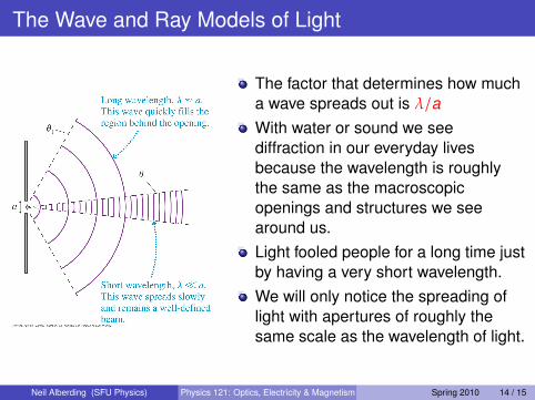
The Wave and Ray Models of Light
The factor that determines how mucha wave spreads out is λ/aWith water or sound we seediffraction in our everyday livesbecause the wavelength is roughlythe same as the macroscopicopenings and structures we seearound us.Light fooled people for a long time justby having a very short wavelength.We will only notice the spreading oflight with apertures of roughly thesame scale as the wavelength of light.
Neil Alberding (SFU Physics) Physics 121: Optics, Electricity & Magnetism Spring 2010 14 / 15

The Wave and Ray Models of Light
Sometimes we treat light like a stream of particles, sometimes like awave and sometimes like a ray. Does light travel in a straight line ornot? The answer depends on the circumstances.
Choosing a Model of LightWhen light passes through openings < 1mm in size, diffractioneffects are usually important. Treat light as a wave.When light passes through openings > 1mm in size, treat it as aray.
Neil Alberding (SFU Physics) Physics 121: Optics, Electricity & Magnetism Spring 2010 15 / 15