Embed Size (px)
Citation preview
Owner's Manual
THE ECONOMIZERrM 6GAS WATER HEATER
FOR POTABLE WATER HEATING ONLY.NOT SUITABLE FOR SPACE HEATING
NOT FOR USE IN MOBILE HOMES.
MODEL NO.
153.333347 30 Gallon
153,333447 40 Gallon
153.333547 50 Galton
Safety hstructionsmnstaHation
OperationCare and Maintenance
TroubleshootingParts List
For Your SafetyAN ODORANT IS ADDED TO THE GAS USED BY THIS WATER HEATER.
C3 Technology _*Gas Water Heaters meetthe new ANSI Z21.10.1 standard that deals
with the accidental or unintended ignition
of flammable vapors, such as thoseemitted by gasoline.
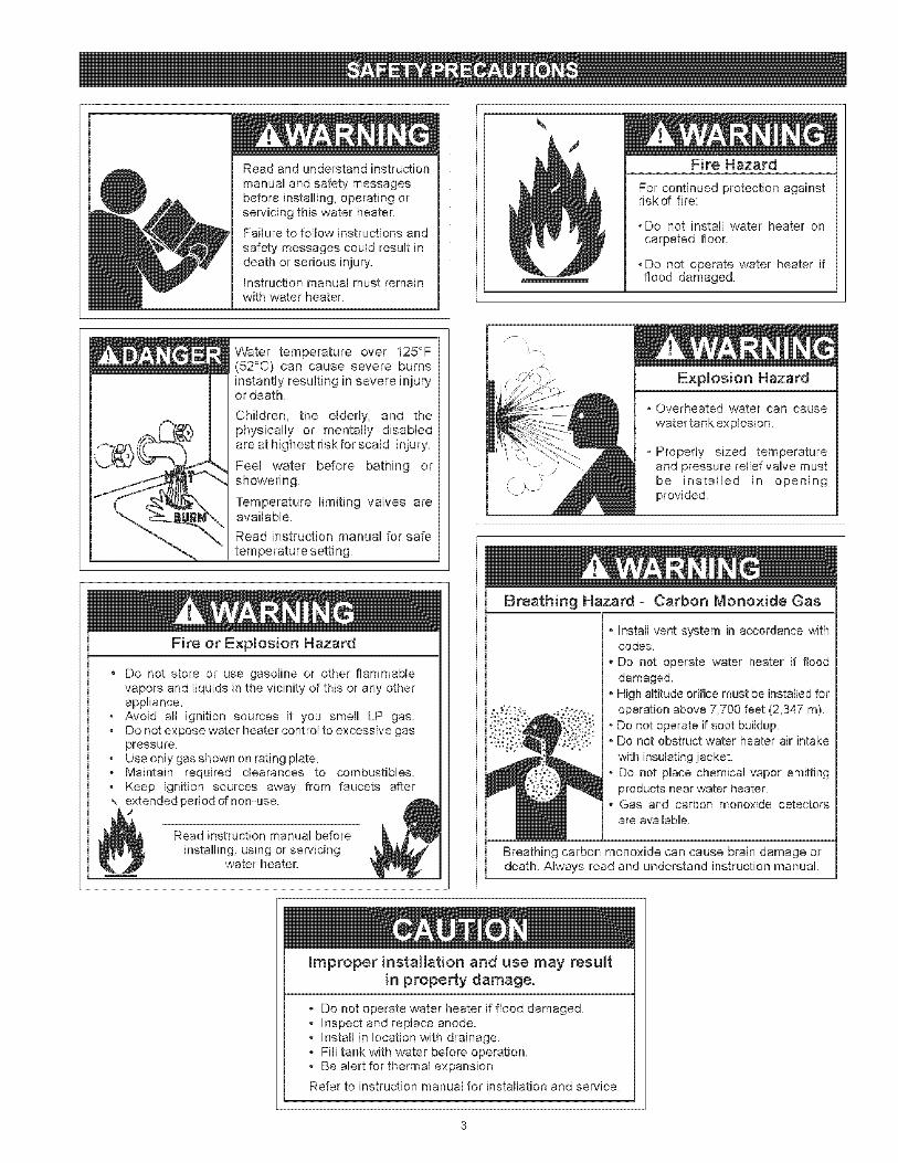
Read and understand instruction
manual and safety messagesbefore instaNing, operating orservicing this water heater.
Failure to follow instructions and
safety messages could result indeath or serious injury'.
Instruction manual must remainwith water heater.
Si no puede leer o entender el ingles y necesita el manual instructivoy/o etiquetas en espa_ol puede obtenerlos Ilamando al1-800-821-2017. NO TRATE DE INSTALAR O OPERAR ESTE
CALENTADOR DEAGUAsi no entiende la informacion en las etiquetaso en el manual instructivo. No hacer caso de esta advertencia podriaresultar en la MU ERTE O GRAVES LESIONES CORPORALES.
WARNING: if the information in theseinstructions is not followed exactly, a fireor explosion may result causing propertydamage, personal injury or death.
--Do not store or use gasoline or otherflammable vapors and liquids in thevicinity of this or any other appliance.
-- WHAT TO DO iF YOU SMELL GAS:
• Do not try to Hght any appliance.
o Do not touch any electrical switch; do
not use any phone in your building.
• immediately call your gas supplierfrom a neighbor's phone. Follow thegas suppHer's instructions,
o if you cannot reach your gas supplier,call the fire department.
--Installation and service must be
performed by a qualified installer,service agency orthe gas supplier.
Sears, Roebuck and Co., Hoffman Estates, _L 60179 U.S.A
PRINTED iN THE USA 0705 _ww,seaPs,co[n PART NO 184230-001
Your safety and the safety of others is extremely important in the installation, use and servicing of this water heater.
Many safetyoreLated messages and instructions have been provided in this manual and on your own water heater to warn you andothers of a potential injury hazard. Read and obey all safety messages and instructions throughout this manuaL, mt is veryimportant that the meaning of each safety message is understood by you and others who instalm, use or service this water heater.
This is the safety amert symbol, ff is used to alert youto potential personal injury hazards. Obey aH safety
messages that follow this symbol to avoid possibleinjury or death.
DANGER indicates an imminentlyhazardous situation which, if not avoided,
could result in death or injury.
WARNmNG indicates a potentially hazardoussituation which, if not avoided, could resultin death or injury.
CAUTmON indicates a potentially hazardoussituation which, if not avoided, may resultin minor or moderate injury.
CAUTLON used without the safety aJertsymbo{ indicates a potentially hazardoussituation which, if not avoided, could resultin property damage.
AH safety messages will generally tell you about the type of hazard, what can happen if you do not follow the safety message andhow to avoid the risk of injury.
IMPORTANT DEF_NIT_ONS
Gas Supplier: The natural gas or propane utility or service who supplies gas for utilization by the gas burningappliances within this application. The gas supplier typically has responsibility for the inspection and code approval ofgas piping up to and including the natural gas meter or propane storage tank of a building. Many gas suppliers alsooffer service and inspection of appliances within the building.
© Sears, Roebuck and Co,
Readandunderstandinstructionmanualandsafetymessagesbeforeinstalling,operatingorservicingthiswaterheaterFailuretofollowinstructionsandsafetymessagescouldresultindeathorseriousinjury,Instructionmanualmustremainwithwaterheater
Fire Hazard
mtinued protection againstriskof fire:
,Do ot install water heater oncarl: .tted floor
,Do ot operate water heater ifflood damaged.
Water temperature over 125°F(52°0) can cause severe burnsinstantly resulting in severe injuryor death_
Children, the elderly, and thephysically or mentally disabledare at highest r[skfor scald injury.
Feel water before bathing orshowering
Temperature limiting valves areavailable.
Read instruction manual for safe
temperature setting.
Fire or Explosion Hazard
Do not store or use gasoline or other flammablevapors and liquids in the vicinity of this or any otherappliance.Avoid all ignition sources if you smell LP gas_
, Do not expose water heater control to excessive gaspressure.
, Use only gas shown on rating plate, Maintain required clearances to combustibles_, Keep ignition sources away from faucets after,, extended period of nen-use.
J
Read instruction manual before
installing, using or sewucmgwater heater.
Explosion Hazard
o Overheated water can cause
water tankexplosion,
-Properly sized temperatureand pressure relief valve mustbe installed in openingprovided.
Breathing Hazard - Carbon Monoxide (}as
• Install vent system in accordance withcodes,
• Do not operate water heater it flood
damaged.
• High altitude or[flee must be installed foroperation above 7,700 feet (2,347 m)
, Do not operate [f soot buildup.• Do not obstruct water heater air intake
with insulating jacket.
• Do not place chemical vapor emittingproducts near water heater.
• Gas and carbon monoxide detectorsare available
Breathing carbon monoxide can cause brain damage ordeath, Always read and understand instruction manual
improper installation and use may resultin property damage.
, Do not operate water heater if flood damagedo Inspect and replace anode.o Install in location with drainage,- Fill tank with water before operation.• Be alert for thermal expansion
Refer to instruction manual for installation and service.
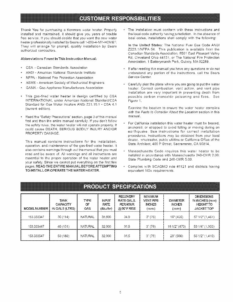
ThankYouforpurchasinga Kenmorewaterheater.Properlyinstalledandmaintained,it shouldgiveyouyearsoftroublefreeservice.IfyoushoulddecidethatyouwantthenewwaterheaterprofessionallyinstalledbySearscall1-800-4-MY-HOME®.Theywillarrangefor prompt,qualityinstallationbySearsauthorizedcontractors.
AbbreviationsFoundInThisInstructionManual:
CSA- CanadianStandardsAssociationANSI- AmericanNationalStandardsInstituteNFPA-NationalFireProtectionAssociationASME-AmericanSocietyofMechanicalEngineersGAMA- Gas Appliance Manufacturers Association
This gas-fired water heater is design certified by CSAINTERNATIONAL under American National Standard/CSA
Standard for Gas Water Heaters ANSI Z21.10.1 • CSA 4.1
(current edition).
Read the "Safety Precautions" section, page 3 of this manualfirst and then the entire manual carefully. If you don't follow
the safety rules, the water heater will not operate properly. It
could cause DEATH, SERIOUS BODILY INJURY AND/ORPROPERTY DAMAGE.
This manual contains instructions for the installation,
operation, and maintenance of the gas-fired water heater. It
also contains warnings through out the manual that you must
read and be aware of. All warnings and all instructions are
essential to the proper operation of the water heater and
your safety. Since we cannot put everything on the first fewpages, READ THE ENTIRE MANUAL BEFORE ATTEMPTINGTO INSTALL OR OPERATE THE WATER HEATER.
The installation must conform with these instructions and
the local code authority having jurisdiction. In the absence of
local codes, installations shall comply with the following:
In the United States: The National Fuel Gas Code ANSI
Z223.1/NFPA 54. This publication is available from theCanadian Standards Association, 8501 East Pleasant Valley
Rd, Cleveland Ohio 44131, or The Nationa! Fire Protection
Association, 1 Batterymarch Park, Quincy, MA 02269.
If after reading this manual you have any questions or do not
understand any portion of the instructions, call the SearsService Center.
Carefully plan the place where you are going to put the water
heater. Correct combustion, vent action, and vent pipe
installation are very important in preventing death from
possible carbon monoxide poisoning and fires. SeeFigure 1.
Examine the location to ensure the water heater complieswith the Facts to Consider About the Location section in this
manual.
For California installation this water heater must be braced,
anchored, or strapped to avoid falling or moving during an
earthquake. See instructions for correct installation
procedures. Instructions may be obtained from your local
dealer, wholesaler, public utilities or California Office of theState Architect, 400 P Street, Sacramento, CA 95814.
Massachusetts Code requires this water heater to beinstalled in accordance with Massachusetts 248-CMR 2.00:
State Plumbing Code and 248-CMR 5.00.
Complies with SCAQMD rule #1121 and districts having
equivalent NOx requirements.
RECOVERY MINIMUM DIMENSIONS
TANK TYPE INPUT RATE GALS, VENT PIPE DIAMETER IN INCHES (ram}CAPACITY OF RATE PERHOUR INCHES INCHES HEIGHTTO
MODELNUMBER IN GALS (LTRS} GAS (Btu/hr) @90°F RISE (ram} (ram} JACKET TOP
153.333347 30 (114) NATURAL 35,500 34.9 3" (76) 16" (406) 57 1/2" (1,461)
153.333447 40 (! 51 ) NATURAL 32,000 31.5 3" (76) 18 1/2" (470) 53 1/4" (! ,353)
153.333547 50 (! 89) NATURAL 32,000 31.5 3" (76) 20" (506) 55 1/2" (! ,410)
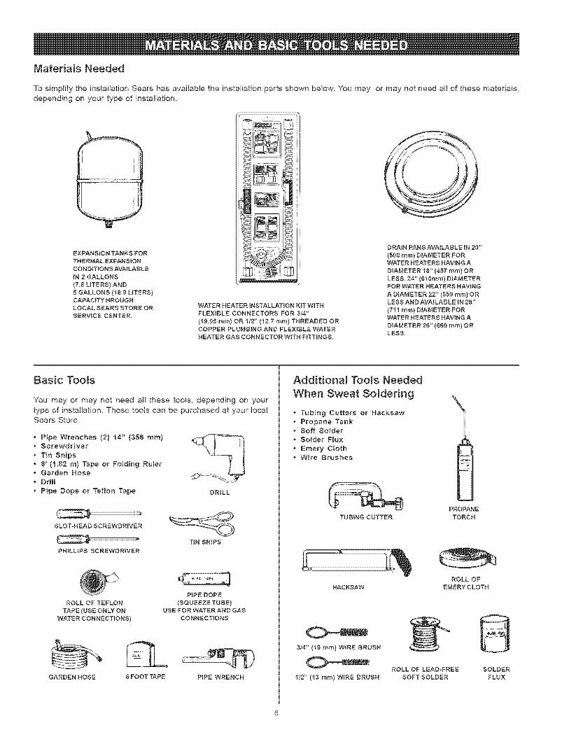
Materials Needed
To simplify the installation Sears has available the installation parts shown below. You may or may not need al! of these materials,
depending on your type of installation.
EXPANSION TANKS FORTHERMAL EXPANSION
CONDITIONS AVAILABLEIN 2 GALLONS
(7=5 LITERS) AND5 GALLONS (18.8 LITERS)CAPACITY NROUGNLOCAL SEARS STORE ORSERVICE CENTER.
_'"'............i!1I_
_,_ I
_'_il I_
WATER HEATER INSTALLATION KIT WITH
FLEXIBLE CONNECTORS FOR 8/4"
(19.05 ram) OR 1/2" (12.7 ram) THREADED ORCOPPER PLUMBING AND FLEXIBLE WATERHEATER GAS CONNECTOR W_TH FITTINGS.
DRAIN PANS AVAILABLE iN 20"
(508 ram) DIAMETER FORWATER HEATERS HAVING A
DIAMETER 18" (457 ram) ORLESS, 24" (510ram) DIAMETERFOR WATER HEATERS HAVING
A DIAMETER 22" (559 ram) ORLESS AND AVAILABLE iN 28"
(711 ram) DIAMETER FORWATER HEATERS HAVING A
DIAMETER 25" (550 ram) ORLESS.
Basic Too_s
You may or may not need all these tools, depending on your
type of installation, These tools can be purchased at your localSears Store,
Pipe Wrenches (2) 14" (356 ram)Screwdriver
Tin Snips6' (1.82 m) Tape or Fo_ding Ru_erGarden HoseDriH
Pipe Dope or Teflon Tape DRILL
SLOT-HEAD SCREWDRIVER
PHILLIPS SCREWDRIVER
TIN SNIPS
ROLL OF TEFLON
TAPE (USE ONLY ON
WATER CONNECTIONS)
PIPE DOPE
(SQUEEZE TUBE)USE FOR WATER AND GAS
CONNECTIONS
GARDEN HOSE 5 FOOT TAPE PIPE WRENCH
Additionam Too_s Needed
When Sweat So_dering
Tubing Cutters or HacksawPropane TankSoft SolderSolder Fmux
Emery C_othWire Brushes
TUBING CUTTER
PROPANETORCH
HACKSAW
ROLL OF
EMERYCLOTH
8/4" (19 ram) WiRE BRUSH
ROLL OF LEAD-FREE
1/2" (13 ram) WIRE BRUSH SOFT SOLDER
SOLDERFLUX
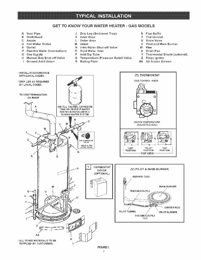
GET TO KNOW YOUR WATER HEATER o GAS MODELS
A Vent Pipe J Drip Leg (Sediment Trap) S F[ueBaff[eB Draft Hood K BnnerDoor T Thermostat
C Anode L Outer door U Drain ValveD Hot Water Outlet M Union V Pilot and Main Burner
E Outlet N BnmetWater Shut-off Valve W FlueF Flexible Water Connections O Cold Water mnlet X Drain Pan
G GasSupply P hmet Dip Tube Y Thermostat Shiemd (optional)
H ManuamGasShut-offVa[ve Q Temperature-Pressure Relief Valve Z Piezo[gaiter
m Ground Joint Union R Rating Plate AA AirlntakeScreen
* tNSTALL JN ACCORDANCE
WiTH LOCAL CODES.
* DRmP LEG AS REQUIRED
BY LOCAL CODES.
TO VENT TERMiNATiON
ON ROOF
INSTALL THERMAL EXPANSIONTANKOR DEVICEIFWATERHEATERIS UNSTALLEDUNA
CLOSEDWATER SYSTEM
W
V
YJ THERMOSTATCOVER
(OPTIONAL)
JXAA
*ALL PIPING MATERIALS TO BESUPPLIED BY CUSTOMERS.
(T) THERMOSTAT
GAS CONTROL KNOB
E
WATER TE_,_PERATURE(ADJUSTING DIAL)
"OFF .... PILOT .... ON"POSITUON POSITION POSITION
TOP ViEW
(V) PILOT & MAIN BURNER
BURNER TUBE
PULOT TUBmNG/
TNERMOCOUPLETCO
UGNmTER ROD
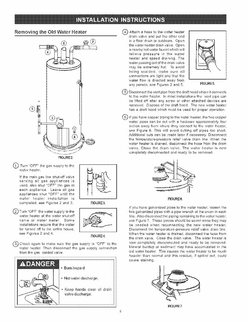
Removing the O_d Water Heater C)
F_GURE2.
Q Turn "OFF" the gas supply to thewater heater.
If the main gas line shut-off valveserving all gas appliances is
used, also shut "OFF" the gas at
each appliance. Leave al! gas
appliances shut "OFF" until thewater heater installation is
completed, see Figures 2 and 3. RGURE 3.
Q Turn "OFF" the water supply to thewater heater at the water shut-off
valve or water meter. Some
installations require that the waterbe turned off to the entire house,
see Figures 2 and 4.FIGURE4.
Check again to make sure the supply is "OFF" to theQ . gaswater heater. Then disconnect the gas supply connection
from the gas control valve.
Burn hazard
• Hotwater discharge.
o Keep hands clear of drainvalve discharge.
®
®
Attach a hose to the water heater
drain valve and put the other end
in a floor drain or outdoors. Open
the water heater drain valve. Opena nearby hot water faucet which wil!
relieve pressure in the water
heater and speed draining. The
water passing out of the drain valvemay be extremely hot. To avoid
being scalded, make sure al!
connections are tight and that the
water flow is directed away from
any person, see Figures 2 and 5. FIGURE 5.
Disconnect the vent pipe from the draft hood where it connectsto the water heater. In most installations the vent pipe can
be lifted off after any screw or other attached devices are
removed. Dispose of the draft hood. The new water heater
has a draft hood which must be used for proper operation.
If you have copper piping to the water heater, the two copper
water pipes can be cut with a hacksaw approximately fourinches away from where they connect to the water heater,
see Figure 6. This wil! avoid cutting off pipes too short.
Additional cuts can be made later if necessary. Disconnect
the temperature-pressure relief valve drain line. When thewater heater is drained, disconnect the hose from the drainvalve. Close the drain valve. The water heater is now
completely disconnected and ready to be removed.
FmGURE&
If you have galvanized pipes to the water heater, loosen the
two galvanized pipes with a pipe wrench at the union in each
line. Also disconnect the piping remaining to the water heater,
see Figure 7. These pieces should be saved since they may
be needed when reconnecting the new water heater.Disconnect the temperature-pressure relief valve drain line.
When the water heater is drained, disconnect the hose fromthe drain valve. Close the drain valve. The water heater is
now completely disconnected and ready to be removed.Mineral buildup or sediment may have accumulated in theold water heater. This causes the water heater to be much
heavier than normal and this residue, if spilled out, could
cause staining.
FmGURE7.
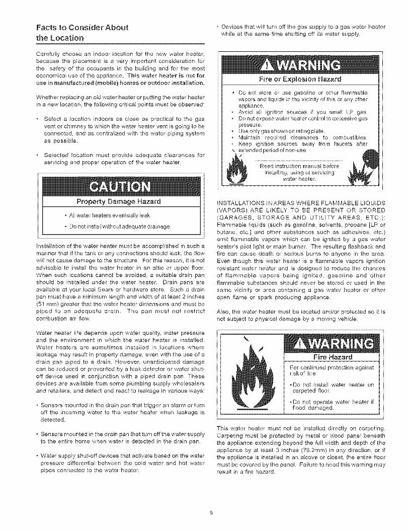
Facts to Consider About
the Location
Carefully choose an indoor location for the new water heater,
because the placement is a very important consideration for
the safety of the occupants in the building and for the mosteconomical use of the appliance_ This water heater is not for
use in manufactured (mobile) homes or outdoor installation.
Whether replacing an old water heater or putting the water heaterin a new location, the following critical points must be observed:
Select a location indoors as close as practical to the gas
vent or chimney to which the water heater vent is going to be
connected, and as centralized with the water piping system
as possible.
Selected location must provide adequate clearances for
servicing and proper operation of the water heater.
Property Damage Hazard
, All water heaters eventually leak
, Do not install without adequate drainage.
Installation of the water heater must be accomplished in such a
manner that if the tank or any connections should leak, the flowwill not cause damage to the structure. For this reason, it is not
advisable to install the water heater in an attic or upper floor.
When such locations cannot be avoided, a suitable drain pan
should be installed under the water beaten Drain pans are
available at your local Sears or hardware store. Such a drain
pan must have a minimum length and width of at least 2 inches
(51 mm) greater that the water heater dimensions and must bepiped to an adequate drain. The pan must not restrictcombustion air flow.
Water heater life depends upon water quality, water pressureand the environment in which the water heater is installed.
Water heaters are sometimes installed in locations where
leakage may result in property damage, even with the use of a
drain pan piped to a drain. However, unanticipated damage
can be reduced or prevented by a leak detector or water shut°
off device used in conjunction with a piped drain pan. Thesedevices are available from some plumbing supply wholesalers
and retailers, and detect and react to leakage in various ways:
• Sensors mounted in the drain pan that trigger an alarm or turnoff the incoming water to the water heater when leakage isdetected.
Sensors mounted in the drain pan that turn off the water supply
to the entire home when water is detected in the drain pan.
Water supply shutooff devices that activate based on the water
pressure differential between the cold water and hot water
pipes connected to the water heater.
• Devices that will turn off the gas supply to a gas water heater
while at the same time shutting off its water supply.
Fire or Explosion Hazard
Do not store or use gasoline or other flammablevapors and liquids in the vicinity of this or any otherappliance.
, Avoid all ignition sources if you smell LP gasDo not expose water heater control to excessive gaspressure.
• Use only gas shown on rating plate., Maintain required clearances to combustibles, Keep ignition sources away from faucets after,, extended period of non-use
Read instruction manual before
installing, using or servicingwater heater.
INSTALLATIONS IN AREAS WHERE FLAMMABLE LIQUIDS
(VAPORS) ARE LIKELY TO BE PRESENT OR STORED
(GARAGES, STORAGE AND UTILITY AREAS, ETC.):Flammable liquids (such as gasoline, solvents, propane [LP or
butane, etc.] and other substances such as adhesives, etc.)
emit flammable vapors which can be ignited by a gas water
heater's pilot light or main burner. The resulting flashback andfire can cause death or serious burns to anyone in the area.
Even though this water heater is a flammable vapors ignition
resistant water heater and is designed to reduce the chances
of flammable vapors being ignited, gasoline and otherflammable substances should never be stored or used in the
same vicinity or area containing a gas water heater or otheropen flame or spark producing appliance.
Also, the water heater must be located and/or protected so it is
not subject to physical damage by a moving vehicle.
Fire Hazard
For continued protection againstrisk of fire:
,Do not install water heater oncarpeted floor.
, Do not operate water heater ifflood damaged.
This water heater must not be installed directly on carpeting.
Carpeting must be protected by metal or wood panel beneath
the appliance extending beyond the full width and depth of the
appliance by at least 3 inches (7&2mm) in any direction, or if
the appliance is installed in an alcove or closet, the entire floormust be covered by the panel. Failure to heed this warning mayresult in a fire hazard.
Fire or Expmosion Hazard
Read instruction manual before instaNing,using or servicing water heater.
• Improper use may result in fire orexplosion.
, Maintain required clearances tocombustibles.
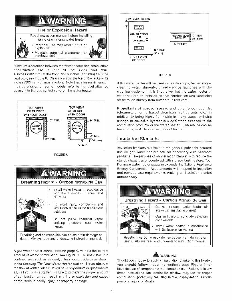
Minimum clearances between the water heater and combustible
construction are 0 inch at the sides and rear,
4 inches (102 ram) at the front, and 6 inches (153 ram) from the
vent pipe, see Figure 8. Clearance from the top of the jacketis 12
inches (305 mm) on most models. Note that a lesser dimension
may be allowed on some models, refer to the labe! attached
adjacent to the gas control valve on the water heater.
TOP V_EW TOP VmEWOF CLOSET OF CLOSET
WITHOUT DOOR WITH DOOR
o" MINN.
FIGURE8.
Breathing Hazard - Carbon Monoxide Gas
Install water heater in accordancewith the instruction manual andNFRA 54.
To avoid injury, combustion andventilation air must be taken fromoutdoors
Do not place chemical vaporemitting products near waterheater,
Breathing carbon monoxide can cause brain damage ordeath. Always read and understand instruction manual
A gas water heater cannot operate properly without the correct
amount of air for combustion, see Figure 9. Do not install in a
confined area such as a closet, unless you provide air as shown
in the Locating The New Water Heater section. Never obstruct
the flow of ventilation air. If you have any doubts or questions at
al!, call your gas supplier. Failure to provide the proper amount
of combustion air can result in a fire or explosion and cause
death, serious bodily injury, or property damage.
.aLl2" MAx. (30 crn)
7
VENTnLATION
FRONT VIEWOF DOOR
AmR DUCT
RGURE9.
If this water heater will be used in beauty shops, barber shops,cleaning establishments, or self=service laundries with dry
cleaning equipment, it is imperative that the water heater orwater heaters be installed so that combustion and ventilation
air be taken directly from outdoors (direct vent).
Propellants of aerosol sprays and volatile compounds,(cleaners, chlorine based chemicals, refrigerants, etc.) in
addition to being highly flammable in many cases, will also
change to corrosive hydrochloric acid when exposed to the
combustion products of the water heater. The results can be
hazardous, and also cause product failure.
Insulation Blankets
Insulation blankets available to the genera! public for external
use on gas water heaters are not necessary with Kenmore
products. The purpose of an insulation blanket is to reduce the
standby heat loss encountered with storage tank heaters. Your
Kenmore water heater meets or exceeds the National Appliance
Energy Conservation Act standards with respect to insulation
and standby loss requirements, making an insulation blanket
unnecessary.
Breathing Hazard - Carbon Monoxide Gas
• Do not obstruct water heater airintake with insulating blanket.
• Gas and carbon monoxide detectorsare available
o Install water heater in accordancewith the instruction manual
Breathing carbon monoxide can cause brain damage ordeath, Always read and understand instructionmanual.
Should you choose to apply an insulation blanket to this heater,
you should follow these instructions (see Figure 1 for
identification of components mentioned below). Failure to follow
these instructions can restrict the air flow required for proper
combustion, potentially resulting in fire, asphyxiation, serious
personal injury or death.
10
Donotapplyinsulationtothetopofthewaterheater,asthiswillinterferewithsafeoperationofthedrafthood.
Donotcovertheouterdoor,thermostatortemperature&pressurereliefvalve.
Donotallowinsulationtocomewithin2"(50_8mm)ofthefloortopreventblockageofcombustionairflowtotheburner.
DonotcovertheinstructionmanualKeepitonthesideofthewaterheaterornearbyforfuturereference.
DoobtainnewwarningandinstructionlabelsfromSearsforplacementontheblanketdirectlyovertheexistinglabels.
Doinspecttheinsulationblanketfrequentlytomakecertainit doesnotsag,therebyobstructingcombustionairflow.
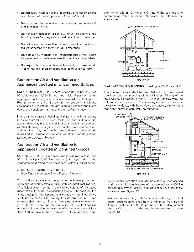
commencewithin12inches(30cm)of thetopandonecommencingwithin12inches(30cm)of thebottomoftheenclosures.
Combustion Air and Ventilation for
Appmiances Located in Unconfined Spaces
UNCONFINED SPACE is space whose volume is not less than50 cubic feet per 1,000 Btu per hour (4.8 m 3 per kW) of the
aggregate input rating of all appliances installed in that space_
Rooms communicating directly with the space in which theappliances are installed, through openings not furnished with
doors, are considered a part of the unconfined space.
In unconfined spaces in buildings, infiltration may be adequate
to provide air for combustion, ventilation and dilution of flue
gases. However, in buildings of tight construction (for example,
weather stripping, heavily insulated, caulked, vapor barrier, etc.),additional air may need to be provided using the methods
described in Combustion Air and Ventilation for Appfiances
Located in Confined Spaces.
Combustion Air and Ventilation for
Appliances Located in Confined Spaces
CONFINED SPACE is a space whose volume is less than50 cubic feet per 1,000 Btu per hour (4.8 m 3 per kW) of the
aggregate input rating of all appliances installed in that space.
A. ALL AIR FROM INSmDE BUILDINGS:
(See Figure 9 on page 9 and Figure 10 below)
The confined space shall be provided with two permanent
openings communicating directly with an additional room(s)
of sufficient volume so that the combined volume of all spaces
meets the criteria for an unconfined space. The total input of
al! gas utilization equipment installed in the combined space
shall be considered in making this determination. Eachopening shal! have a minimum free area of one square inch
per 1,000 Btu per hour (22 cm2/kW) of the total input rating ofal!
gas utilization equipment in the confined space, but not less
than 100 square inches (845 cm2). One opening shal!
FIGURE1O.
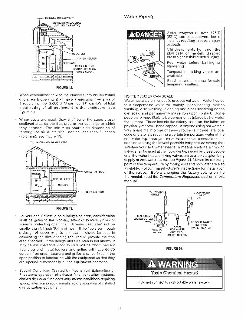
B. ALL AIR FROM OUTDOORS: (See Figures 9, 11,12 and 13)
The confined space shall be provided with two permanentopenings, one commencing within 12 inches (30 cm) of the
top and one commencing within 12 inches (30 cm) from the
bottom of the enclosure. The openings shall communicatedirectly, or by ducts, with the outdoors or spaces (craw! or attic)
that freely communicate with the outdoors.
ALT. INLETAIR VENTULATUON LOUVERS
FmGURE11,
When directly communicating with the outdoors, each opening
shall have a minimum free area of 1 square inch per 4,000 Btu
per hour (5.5 cm_/kW) of total input rating of all equipment in theenclosure, see Figure 12.
When communicating with the outdoors through vertical
ducts, each opening shall have a minimum free area of
1 square inch per 4,000 BTU per hour (5_5 cm_/kW) of total
input rating of all equipment in the enclosure, seeFigure 12.
11
VENTILATION LOUVERS
(EACH END OF ATTIC)
FIGURE 12.
When communicating with the outdoors through horizontal
ducts, each opening shall have a minimum free area of1 square inch per 2,000 BTU per hour (11 cm_/kW) of total
input rating of all equipment in the enclosure, see
Figure 13.
When ducts are used, they shall be of the same cross-sectional area as the free area of the openings to which
they connect. The minimum short side dimension ofrectangular air ducts shall not be less than 3 inches
(76.2 ram), see Figure 13.
OUTLET NR DUCT
Water Piping
Water temperature over 125°F(52°0) can cause severe burnsinstantly resulting in severe injuryor death.
Children, eldedy, and thephysically or mentally disabledare at highest riskfor scald injury,
Fee[ water before bathing orshowering.
Temperature limiting valves areavailable.
Read instruction manual for safetemperature setting
HOTTER WATER CAN SCALD:
Water heaters are intended to produce hot water. VVater heated
to a temperature which will satisfy space heating, clotheswashing, dish washing, cleaning and other sanitizing needscan scald and permanently injure you upon contact. Some
people are more likely to be permanently injured by hot water
than others. These include the elderly, children, the infirm, orphysically/mentally handicapped. Ifanyone using hotwaterin
your home fits into one of these groups or if there is a localcode or state law requiring a certain temperature water at the
hot water tap, then you must take special precautions. Inaddition to using the lowest possible temperature setting that
satisfies your hot water needs, a means such as a *mixingvalve, shall be used at the hot water taps used by these people
or at the ,water heater. Mixing valves are available at plumbingsupply or hardware stores, see Figure 14. Valves for reducing
point of use temperature by mixing cold and hot water are alsoavailable. Follow manufacturer's instructions for installation
of the valves. Before changing the factory setting on thethermostat, read the Temperature Regulation section in thismanual.
INLET AiR DUCT
FIGURE13.
Louvers and Grilles: In calculating free area, consideration
shall be given to the blocking effect of louvers, grilles orscreens protecting openings. Screens used shall not besmaller than 1/4 inch (6.4 ram) mesh. If the free area through
a design of louver or grille is known, it should be used incalculating the size opening required to provide the free
area specified. If the design and free area is not known, itmay be assumed that wood louvers will be 20-25 percent
free area and metal louvers and grilles will have 60-75percent free area. Louvers and grilles shall be fixed in theopen position or interlocked with the equipment so that they
are opened automatically during equipment operation.
Special Conditions Created by Mechanical Exhausting orFireplaces: operation of exhaust fans, ventilation systems,
clothes dryers or fireplaces may create conditions requiringspecial attention to avoid unsatisfactory operation of installed
gas utilization equipment.
*MIXING NOT WATERVALVE OUTLET ON
WATER HEATER
WATERHEATER
FIGURE14.
Toxic Chemicam Hazard
. Do not connect to non-potable water system.
12
Thiswaterheatershallnotbeconnectedtoanyheatingsystemsor component(s)usedwitha non-potablewaterheatingappliance.
Allpipingcomponentsconnectedtothisunitforspaceheatingapplicationsshallbesuitableforusewithpotablewater.
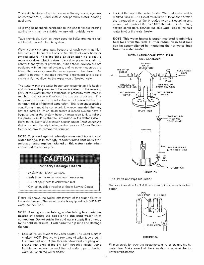
Lookatthetopofthewaterheater.Thecoldwaterinletismarked'COLD".Puttwoorthreeturnsofteflontapearoundthethreadedendof thethreaded-to-sweatcouplingandaroundbothendsofthe3/4"NPTthreadednipple.Usingflexibleconnectors,connectthecoldwaterpipetothecoldwaterinletofthewaterheater.
Toxicchemicals,suchasthoseusedforboilertreatmentshallnotbeintroducedintothissystem.
Watersupplysystemsmay,becauseofsucheventsashighlinepressure,frequentcut-offsortheeffectsofwaterhammeramongothers,haveinstalleddevicessuchaspressurereducingvalves,checkvalves,backflowpreventers,etc.tocontrolthesetypesofproblems.Whenthesedevicesarenotequippedwithaninternalby-pass,andnoothermeasuresaretaken,thedevicescausethewatersystemto beclosed.Aswateris heated,it expands(thermalexpansion)andclosedsystemsdonotallowfortheexpansionofheatedwater.
Thewaterwithinthewaterheatertankexpandsasit isheatedandincreasesthepressureofthewatersystem.Iftherelievingpointofthewaterheater'stemperature-pressurereliefvalveisreached,thevalvewill relievetheexcesspressure.Thetemperature-pressurereliefvalveis notintendedfor theconstantreliefofthermalexpansion.Thisisanunacceptableconditionandmustbecorrected.It is recommendedthatanydevicesinstalledwhichcouldcreateadosedsystemhaveaby-passand/orthesystemhaveanexpansiontanktorelievethepressurebuiltbythermalexpansioninthewatersystem.RefertotheTheTma! Expat_sion section under Troubleshooting
Guide or contact local plumbing authority or local Sears ServiceCenter on how to control this situation.
NOTE: To protect against untimely corrosion of hot and cold
water fittings, it is strongly recommended that dioelectricunions or couplings be installed on this water heater when
connected to copper pipe.
Property Damage Hazard
o Avoid water heater damage.
• Install thermal expansion tank if necessary.
, Do not apply heat to cold water inlet
, Contact qualified installer or Sears Service Center.
Figure 15 shows the typical attachment of the water piping to
the water heater. The water heater is equipped with 3/4" NPTwater connections.
NOTE: [f using copper tubing, solder tubing to an adapterbefore attaching the adapter to the cold water inlet
connection. Do not somder the cold water suppmy Hne directly
to the cold water inlet. It will harm the dip tube and damagethe tank.
NOTE: This water heater is super insuhted to minimizeheat loss from the tank. Further reduction in heat loss
can be accomplished by insuhting the hot water linesfrom the water heater.
INSTALLATION COMPLETED USINGINSTALLATION KIT
FLEXIBLEWATER
CONRSGTORSHOT WATER
OUTLET
tTHREADED TO
l SHUTOFFVALVE
THREADED TO
DRAFT HOOD
TEMPERATURS__PRESSURE
REUEF VALVE
DISCHARGE PIPE
(Do not cap or plug)
A_RGAP
FLOOR DRAIN
FIGURE 15.
T & P Valve and Pipe Insuhtion
Remove insulation for T & P valve and pipe connections fromcarton.
PiPEINSULATION FLUE PmPE
Look at the top cover of the water heater. The water outlet is
marked "HOT". Put two or three turns of teflon tape around
the threaded end of the threadedoto-sweat coupling and
around both ends of the 3/4" NPT threaded nipple. Using
flexible connectors, connect the hot water pipe to the hotwater outlet on the water heater.
FIGURE 15A.
Fit pipe insulation over the incoming cold water line and the hot
water line. Make sure that the insulation is against the topcover of the heater.
13
FitT&Pvalveinsulationovervalve.MakesurethattheinsulationdoesnotinterferewiththeleveroftheT&Pvalve. HOTWATER
Secureal!insulationusingtape.
Temperature-Pressure Relief Valve
Expmosion Hazard
Temperature-pressure relief valvemust comply w_h ANSI Z21,22and ASME code,
Properly sized temperature-pressure relief valve must be
insLalled in opening provided,
Can result in overheating andexcessive tank pressure
Can cause serious injury or death.
DRAFT HOOD VALVE NOT SHOWN}
DUSCHARGE PmPE
DO NOT CAP OR PLUG)
VALVE
FLOOR DRAmN
This heater is provided with a properly certified combination
temperature - pressure relief valve by the manufacturer.
The valve is certified by a nationally recognized testing laboratory
that maintains periodic inspection of production of listed
equipment as meeting the requirements for Relief Valves andAutomatic Gas Shut-off Devices for Hot Water Supply Systems,
ANSI Z21.22 and the code requirements of ASME.
If replaced, the valve must meet the requirements of local
codes, but not less than a combination temperature and
pressure relief valve certified as indicated in the aboveparagraph.
The valve must be marked with a maximum set pressure not to
exceed the marked hydrostatic working pressure of the water
heater (150 psi = 1,035kPa) and a discharge capacity not less
than the water heater input rate as shown on the model ratingplate.
For safe operation of the water heater, the relief valve must not
be removed from its designated opening nor plugged.
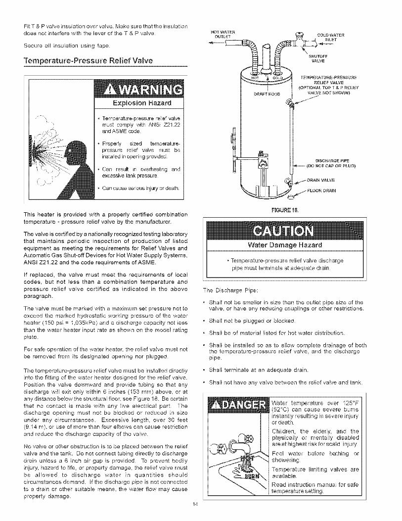
The temperature-pressure relief valve must be installed directlyinto the fitting of the water heater designed for the relief valve.
Position the valve downward and provide tubing so that any
discharge will exit only within 6 inches (153 mm) above, or atany distance below the structural floor, see Figure 16. Be certain
that no contact is made with any live electrical part. The
discharge opening must not be blocked or reduced in size
under any circumstances. Excessive length, over 30 feet(9.14 m), or use of more than four elbows can cause restriction
and reduce the discharge capacity of the valve.
No valve or other obstruction is to be placed between the relief
valve and the tank. Do not connect tubing directly to discharge
drain unless a 6 inch air gap is provide& To prevent bodilyinjury, hazard to life, or property damage, the relief valve must
be allowed to discharge water in quantities should
circumstances demand. If the discharge pipe is not connected
to a drain or other suitable means, the water flow may causeproperty damage.
FIGURE1&
Water Damage Hazard
, Temperatureopressure relief valve discharge
pipe must terminate at adequate drain.
The Discharge Pipe:
* Shall not be smaller in size than the outlet pipe size of thevalve, or have any reducing couplings or other restrictions.
* Shall not be plugged or blocked.
* Shall be of material listed for hot water distribution.
. Shall be installed so as to allow complete drainage of boththe temperature-pressure relief valve, and the dischargepipe.
* Shall terminate at an adequate drain.
. Shall not have any valve between the relief valve and tank.
Water temperature over 125°F(52°0) can cause severe burnsinstantly resulting in severe injuryor death,
Children, the elderly, and thephysicaNy or mentally disabledare at highest risk for scald injury.
Feel water before bathing orshowering.
Temperature limiting valves areavailable
Read instruction manual for safetemperature setting.
14
Thetemperature-pressurereliefvalvemustbemanuallyoperatedat leastoncea year.Cautionshouldbetakentoensurethat(1)nooneisinfrontoforaroundtheoutletofthetemperature-pressurereliefvalvedischargeline,and(2)thewatermanuallydischargedwillnotcauseanybodilyinjuryorpropertydamagebecausethewatermaybeextremelyhot.
Ifaftermanuallyoperatingthevalve,itfailstocompletelyresetandcontinuesto releasewater,immediatelyclosethecoldwaterinlettothewaterheater,followthedraininginstructions,andreplacethetemperature-pressurereliefvalvewitha newone.
Filling the Water Heater
Property Damage Hazard
. Avoid water heater damage
• Fill tank with water before operating.
Never use this water heater unless it is completely full of water.
To prevent damage to the tank, the tank must be filled with
water. Water must flow from the hot water faucet before turning
"ON" gas to the water heater.
To fill the water heater with water:
• Close the water heater drain valve by turning the handle to
the right (clockwise). The drain valve is on the lower front ofthe water heater.
and mechanically actuated vent dampers). Before installation
of any vent damper, consult your local Sears Service Center or
the local gas supplier for further information.
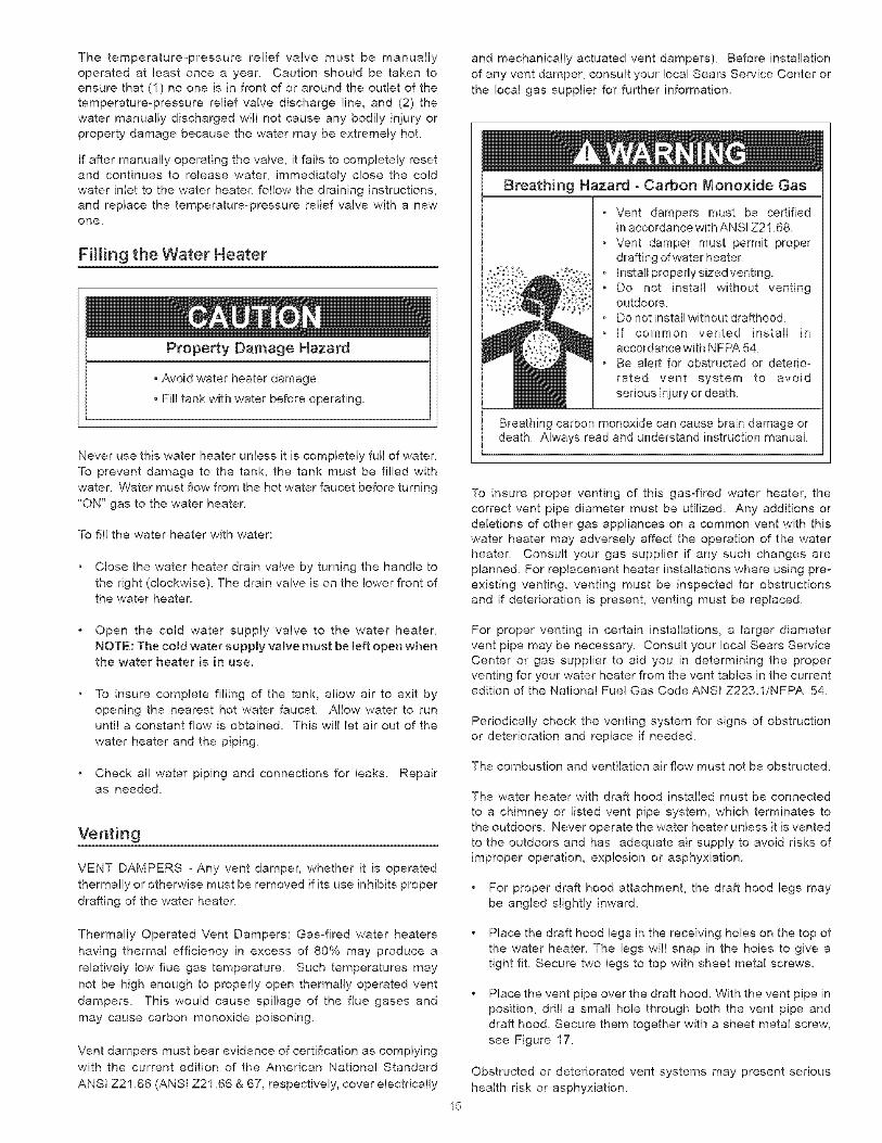
Breathing Hazard - Carbon Monoxide Gas
Vent dampers must be certifiedin accordance with ANSI Z21.68.
• Vent damper must permit properdrafting of water heater
• Install properlysizedventing.
Do not install without ventingoutdoors
Do not install without drafthood.• If common vented install in
accordance with NFPA 54.
Be alert for obstructed or deterio-
rated vent system to avoid
serious injury or death.
Breathing carbon monoxide can cause brain damage ordeath. Always read and understand instruction manual.
To insure proper venting of this gas-fired water heater, the
correct vent pipe diameter must be utilized. Any additions ordeletions of other gas appliances on a common vent with this
water heater may adversely affect the operation of the waterheater. Consult your gas supplier if any such changes are
planned. For replacement heater installations where using pre-existing venting, venting must be inspected for obstructions
and if deterioration is present, venting must be replaced.
Open the cold water supply valve to the water heater.
NOTE: The cold water supply valve must be [eft open whenthe water heater is in use.
To insure complete filling of the tank, allow air to exit by
opening the nearest hot water faucet. Allow water to rununtil a constant flow is obtained. This will let air out of the
water heater and the piping.
For proper venting in certain installations, a larger diametervent pipe may be necessary. Consult your local Sears Service
Center or gas supplier to aid you in determining the properventing for your water heater from the vent tables in the currentedition of the National Fuel Gas Code ANSI Z223.1/NFPA 54.
Periodically check the venting system for signs of obstructionor deterioration and replace if needed.
Check all water piping and connections for leaks. Repairas needed.
Venting
VENT DAMPERS - Any vent damper, whether it is operated
thermally or othePcvise must be removed if its use inhibits proper
drafting of the water heater.
The combustion and ventilation air flow must not be obstructed.
The water heater with draft hood installed must be connected
to a chimney or listed vent pipe system, which terminates tothe outdoors. Never operate the water heater unless it is vented
to the outdoors and has adequate air supply to avoid risks ofimproper operation, explosion or asphyxiation.
For proper draft hood attachment, the draft hood legs may
be angled slightly inward.
Thermally Operated Vent Dampers: Gas-fired water heaters
having thermal efficiency in excess of 80% may produce a
relatively low flue gas temperature. Such temperatures may
not be high enough to properly open thermally operated vent
dampers. This would cause spillage of the flue gases and
may cause carbon monoxide poisoning.
Vent dampers must bear evidence of certification as complying
with the current edition of the American National Standard
ANSI Z21.68 (ANSI Z21.66 & 67, respectively, cover electrically
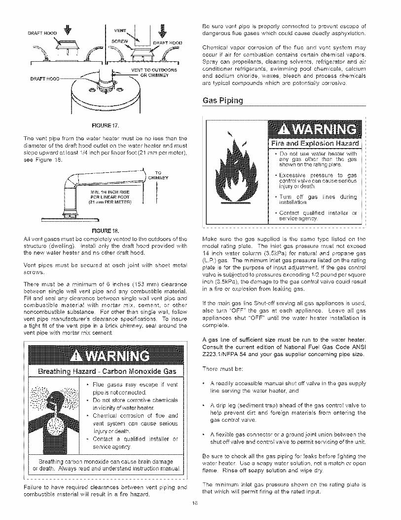
Place the draft hood legs in the receiving holes on the top ofthe water heater. The legs will snap in the holes to give a
tight fit. Secure two legs to top with sheet metal screws.
Place the vent pipe over the draft hoe& With the vent pipe inposition, drill a small hole through both the vent pipe and
draft hood. Secure them together with a sheet metal screw,
see Figure 17.
Obstructed or deteriorated vent systems may present serious
health risk or asphyxiation.
15
DRAFT HOOD
Be sure vent pipe is properly connected to prevent escape of
dangerous flue gases which could cause deadly asphyxiation.
Chemical vapor corrosion of the flue and vent system may
occur if air for combustion contains certain chemical vapors.Spray can propellants, cleaning solvents, refrigerator and air
conditioner refrigerants, swimming pool chemicals, calcium
and sodium chloride, waxes, bleach and process chemicals
are typical compounds which are potentially corrosive.
Gas Piping
FIGURE17.
The vent pipe from the water heater must be no less than thediameter of the draft hood outlet on the water heater and must
slope upward at least 1/4 inch per linear foot (21 mm per meter),
see Figure 18.
TO
CHIMNEY
RGURE 18.
All vent gases must be completely vented to the outdoors of the
structure (dwelling). Install only the draft hood provided withthe new water heater and no other draft hood.
Vent pipes must be secured at each joint with sheet metalscrews.
There must be a minimum of 6 inches (153 mm) clearance
between single wall vent pipe and any combustible material.
Fill and seal any clearance between single wal! vent pipe andcombustible material with mortar mix, cement, or othernoncombustible substance. For other than single wall, follow
vent pipe manufacturer's clearance specifications. To insurea tight fit of the vent pipe in a brick chimney, seal around the
vent pipe with mortar mix cement.
• Flue gases may escape if vent
pipe is not connected,, Do not store corrosive chemicals
in vicinity of water heater,, Chemical corrosion of flue and
vent system can cause serious
injury or death
- Contact a qualified instalbr or
sen/ice agency,
Breathing carbon monsxide can cause brain damageor death. Always read and understand instruction manual.
Failure to have required clearances between vent piping andcombustible material will result in a fire hazard.
Fire and Explosion HazardDo not use water heater withany gas other than the gasshown on the rating plate.
Excessive pressure to gascontrol valve can cause seriousinjury or death
Turn off gas lines duringinstallation
Contact qualified installer orservice agency.
16
Make sure the gas supplied is the same type listed on the
model rating plate. The inlet gas pressure must not exceed
14 inch water column (3.5kPa) for natural and propane gas
(L.P.) gas. The minimum inlet gas pressure listed on the rating
plate is for the purpose of input adjustment. If the gas control
valve is subjected to pressures exceeding 1/2 pound per squareinch (3.5kPa), the damage to the gas control valve could result
in a fire or explosion from leaking gas.
If the main gas line Shut-off serving all gas appliances is used,
also turn "OFF" the gas at each appliance. Leave all gas
appliances shut "OFF" until the water heater installation iscomplete.
A gas line of sufficient size must be run to the water heater.Consult the current edition of National Fuel Gas Code ANSI
Z223.1/NFPA 54 and your gas supplier concerning pipe size.
There must be:
* A readily accessible manual shut off valve in the gas supply
line serving the water heater, and
* A drip leg (sediment trap) ahead of the gas control valve to
help prevent dirt and foreign materials from entering the
gas control valve.
* A flexible gas connector or a ground joint union between the
shut off valve and control valve to permit servicing of the unit.
Be sure to check a!! the gas piping for leaks before lighting the
water heater. Use a soapy water solution, not a match or open
flame. Rinse off soapy solution and wipe dry.
The minimum inlet gas pressure shown on the rating plate is
that which will permit firing at the rated input.
Breathing Hazard - Carbon Monoxide Gas
o High altitude orifice must be installed for
operation above 7,700 feet (2,347 m).
• Contact a qualified installer or service
agency
BreatMng carbon monoxide can cause brain damage ordeath, Always read and understand instruction manual.
Water heaters covered in this manual have been tested and
approved for installation at elevations up to 7,700 feet (2,347 m)
above sea level. For installation above 7,700 feet (2,347m),
the water heater's Btu input should be reduced at the rate of 4
percent for each 1,000 feet (305 m) above sea level which
requires replacement of the burner orifice in accordance withthe National Fuel Gas Code ANSI Z223.1/NFPA 54. Contact
your local gas supplier for further information.
Failure to replace the standard orifice with the proper highaltitude orifice when installed at elevations above 7,700 feet
(2,347 m) could result in improper and inefficient operation of
the appliance, producing carbon monoxide gas in excess of
the safe limits. This could result in serious injury or death.
Contact your local gas supplier for any specific changes that
may be required in your area.
Sediment Traps
Fire and Explosion Hazard
" Contaminants in gas lines cancause fire or explosion
• Clean all gas piping beforeinstallation.
• instal! dnp leg in accordance withNFPA 54
Contaminants in the gas lines may cause improper operationof the gas control valve that may result in fire or explosion.
Before attaching the gas line be sure that all gas pipe is clean
on the inside. To trap any dirt or foreign material in the gas
supply line, a drip leg (sometimes called a sediment trap)
must be incorporated in the piping. The drip leg must be readily
accessible. Install in accordance with the Gas Piping section.Refer to the current edition of the National Fuel Gas Code,ANSI Z223.1/NFPA 54.
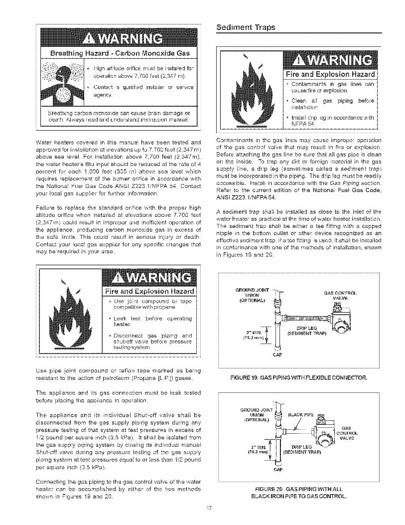
A sediment trap shall be installed as close to the inlet of thewater heater as practical at the time of water heater installation.
The sediment trap shall be either a tee fitting with a capped
nipple in the bottom outlet or other device recognized as an
effective sediment trap. If a tee fitting is used, it shall be installedin conformance with one of the methods of installation, shown
in Figures 19 and 20.
Fire and Explosion Hazard
, Use ioint compound or tapecompatible with propane
, Leak test before operatingheater.
Disconnect gas piping andshut=off valve before pressuretesting system
GROUND JOINT -UNION
(OPTIONAL)
CAP
FIGURE 19. GAS PIPING WITH FLEXIBLE CONNECTOR.Use pipe joint compound or teflon tape marked as being
resistant to the action of petroleum (Propane [LR]) gases.
The appliance and its gas connection must be leak tested
before placing the appliance in operation.
The appliance and its individual Shut-off valve shall be
disconnected from the gas supply piping system during any
pressure testing of that system at test pressures in excess of
1/2 pound per square inch (3.5 kPa). it shall be isolated from
the gas supply piping system by closing its individual manual
Shut-off valve during any pressure testing of the gas supply
piping system at test pressures equal to or less than 1/2 pound
per square inch (3.5 kPa).
Connecting the gas piping to the gas control valve of the water
heater can be accomplished by either of the two methods
shown in Figures 19 and 20.
17
CAP
FIGURE 20. GAS PIPING WiTH ALL
BLACK IRON PIPE TO GAS CONTROL.
FOR YOUR SAFETY READ BEFORE UGHTING
WARNING: If you do not follow these instructions exactly, a fire or
explosion may result causing property damage, personal injury or loss of life.
BEFORE OPERATING: ENTIRE SYSTEM MUST BE FILLED W}TH WATER AND AIR PURGED FROM ALL LINES.
A. This appliance has a pilot which is lit by a piezo electricgas ignition system. Do not open the inner door of theappliance and try to light the pilot by hand.
B. BEFORE UGHTING smell all around the applianoe areafor gas. Be sure to smell next to the floor because somegas is heavier than air and will settle on the floor.
WHAT TO DO IFYOU SMELL GAS:
Do not try to light any appliance.Do not touch any electric switch; do not use any phonein your building.Immediately call your gas supplier from a neighbor'sphone. Follow the gas supplier's instructions.
C.
D.
If you cannot reach your gas supplier, call the firedepartment.
Use only your hand to push in or turn the gas controlknob. Never use tools. If the knob will not push in or turn
by hand, don't try to repair it, call a qualified servicetechnician. Force or attempted repair may result in a fireor explosion.
Do not use this appliance if any part has been underwater. Immediately contact a qualified installer or serviceagency to replace a flooded water heater. Do not attempt
to repair the unit! It must be replaced!
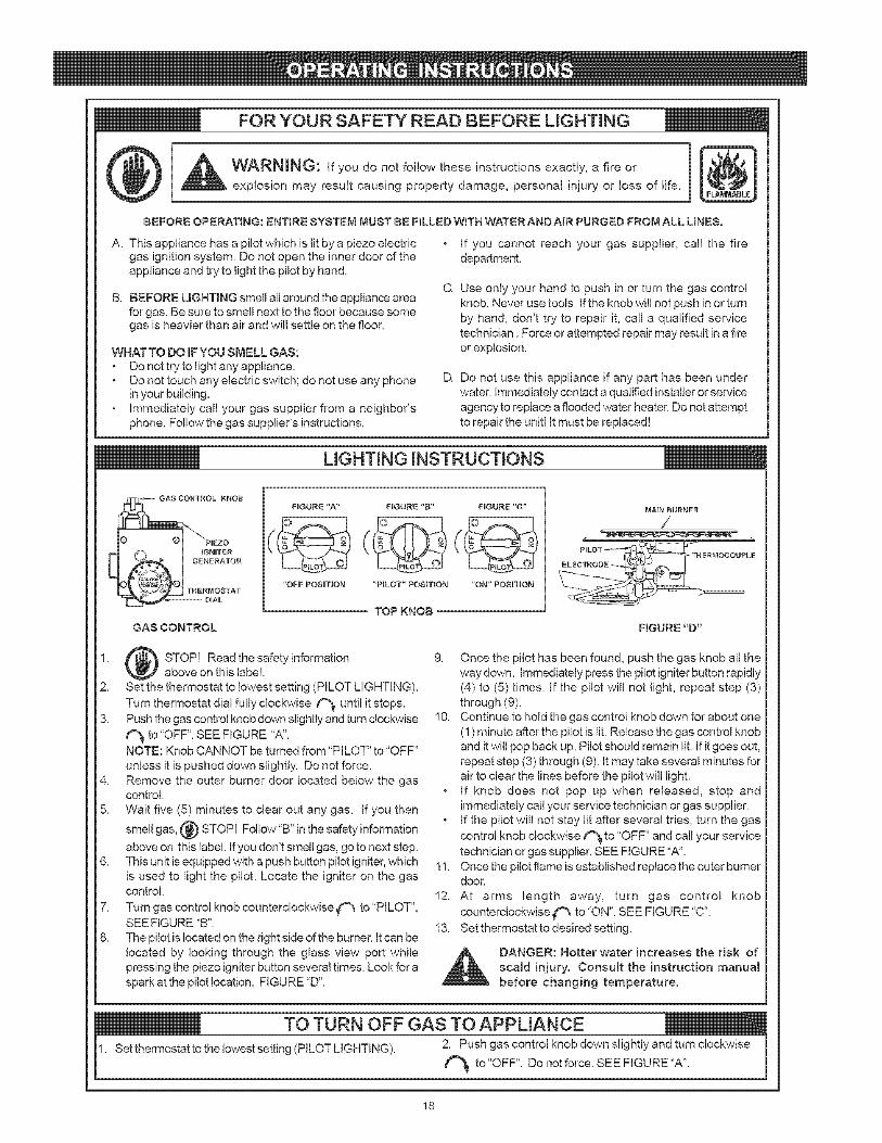
UGHTING iNSTRUCTiONS
1,
2.
3.
4,
5.
7,
8.
FmGURE "A"
"OFF POSITION
HGURE "g" HGURE "C"
"PILOT" POSITION "ON" POSITRON
MAI_ 8U_NER
/
GAS CONTROL
TOPKNOB
FIGURr: "D"
STOPI Read the safety informationabove on this label.
Set the thermostat to lowest setting (PILOT LIGHTING).
Turn thermostat dial fully clockwise t_ until it stops.Push the gas control knob down slightly and turn clockwise
f_ to"OFF", SEE FIGURE 'W'.NOTE: Knob CANNOT be turned from "PILOT" to "OFF"
unless it is pushed down slightly. Do not force.Remove the outer burner door located below the gascontrol.
Wait five (5) minutes to clear out any gas. If you then
smell gas, @ STOPI Follow"B" in the safety information
above on this label. If you don't smell gas, go to next step.This unit is equipped with a push button pilot igniter, whichis used to light the pilot. Locate the igniter on the gascontrol.
Turn gas control knob counterclockwise _'_ to "PILOT",SEE FIGURE "B".
The pilot is located on the right side of the burner. It can belocated by looking through the glass view port whilepressing the piezo igniter button several times. Look for a
spark at the pilot location, FIGURE "D'.
9. Once the pilot has been found, push the gas knob all theway down. Immediately press the pilot igniter button rapidly(4) to (5) times. If the pilot will not light, repeat step (3)
through (9).10. Continue to hold the gas control knob down for about one
(!) minute after the pilot is lit. Release the gas control knoband it will pop back up. Pilot should remain lit. If it goes out,
repeat step (3) through (9). It may take several minutes forair to clear the lines before the pilot will light.
° If knob does not pop up when released, stop andimmediately call your service technician or gas supplier.
° If the pilot will not stay lit after several tries, turn the gas
control knob clockwise f_ to "OFF" and call your servicetechnician or gas supplier. SEE FIGURE "A".
11. Once the pilot flame is established replace the outer burnerdoor.
12. At arms length away, turn gas control knob
counterclockwise ('_ to "ON". SEE FIGURE "C".13. Set thermostat to desired setting.
DANGER: Hotter water increases the risk of
scald injury. Consuk the instruction manual
before changing temperature.
_to "OFF". Do not force. SEE FIGURE "A".
18
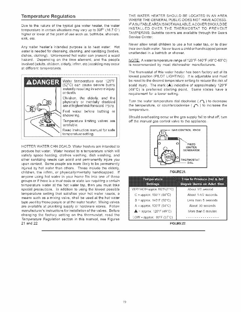
Temperature Regulation
Due to the nature of the typical gas water heater, the water
temperature in certain situations may vary up to 30F ° (16.7 C °)
higher or lower at the point of use such as, bathtubs, showers,
sink, etc.
Any water heater's intended purpose is to heat water. Hotwater is needed for cleansing, cleaning, and sanitizing (bodies,
dishes, clothing). Untempered hot water can present a scald
hazard. Depending on the time element, and the people
involved (adults, children, elderly, infirm, etc.)scalding may occurat different temperatures.
Water temperature over 125°F(52°C) can cause severe burnsinstantly resulting in severe injuryor death
Children, the elderly, and thephysically or mentally disabledare at highest fiskforscald injury,
Fed water before bathing orshowering,
Temperature limiting valves areavailable_
Read instruction manual for safetemperature setting,
THE WATER HEATER SHOULD BE LOCATED IN AN AREA
WHERE THE GENERAL PUBLIC DOES NOT HAVE ACCESS.
IF ASUITABLEAREA IS NOTAVAILABLE,A COVER SHOULD BEINSTALLED OVER THE THERMOSTAT TO PREVENT
TAMPERING. Suitable covers are available through the SearsService Center.
Never allow small children to use a hot water tap, or to draw
their own bath water. Never leave a child or handicapped personunattended in a bathtub or shower.
NOTE: A water temperature range of 120°Fo140°F (49°C-60°C)
is recommended by most dishwasher manufacturers.
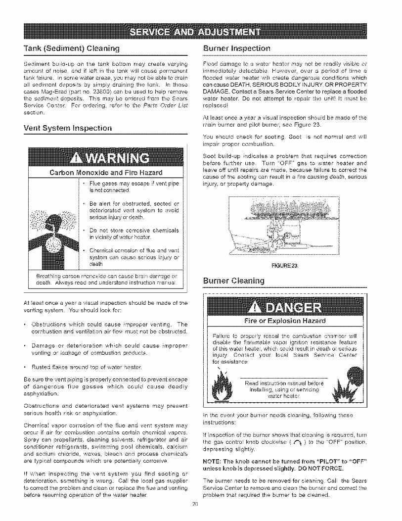
The thermostat of this water heater has been factory set at its
lowest position (PILOT LIGHTING). It is adjustable and must
be reset to the desired temperature setting to reduce the risk of
scald injury. The mark (,&) indicative of approximately 120°F
(49°C) is preferred starting point. Some states have a
requirement for a lower setting.
Turn the water temperature dial clockwise ( _ ) to decrease
the temperature, or counterclockwise ( _ ) to increase thetemperature.
Should overheating occur or the gas supply fail to shut off, turn
off the manual gas control valve to the appliance.
HOTTER WATER CAN SCALD: Water heaters are intended to
produce hot water. Water heated to a temperature which wil!satisfy space heating, clothes washing, dish washing, and
other sanitizing needs can scald and permanently injure you
upon contacL Some people are more likely to be permanently
injured by hot water than others. These include the elderly,
children, the infirm, or physically/mentally handicapped. If
anyone using hot water in your home fits into one of thesegroups or if there is a local code or state law requiring a certain
temperature water at the hot water tap, then you must take
special precautions. In addition to using the lowest possible
temperature setting that satisfies your hot water needs, ameans such as a mixing valve, shall be used at the hot water
taps used by these people or at the water heater. Mixing valves
are available at plumbing supply or hardware stores. Followmanufacturer's instructions for installation of the valves. Before
changing the factory setting on the thermostat, read the
Temperature Regulation section in this manual, see Figures21 and 22.
FIGURE 21,
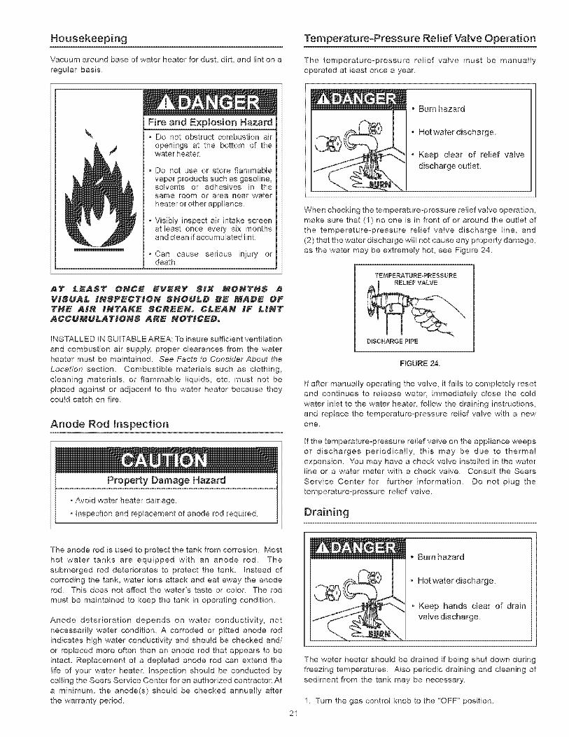
-E
VERY HOT= approx.160°F (71°C)
C = approx. 150°F (66°C)
B = approx. 140°F (60°C)
A = approx. 130°F (54'>C)
A = approx. 120°F (49°C)
LOW = approx. 80°F (27°C)
RGURE 22.
About 1/2 second
About 1-1/2 seconds
Less than 5 seconds
About 30 seconds
More than 5 minutes
19
Tank (Sediment) C_eaning
Sediment build-up on the tank bottom may create varyingamount of noise, and if left in the tank will cause permanent
tank failure. In some water areas, you may not be able to drainall sediment deposits by simply draining the tank. In these
cases Mag-Erad (part no. 23600) can be used to help removethe sediment deposits. This may be ordered from the Sears
Service Center. For ordering, refer to the Parts Order Listsection.
Vent System _nspection
Carbon Monoxide and Fire Hazard
Flue gases may escape if vent pipeis not connected.
o Be alert for obstructed, sooted ordeteriorated vent system to avoidserious injury or death.
Do not store corrosive chemicals
in vicinity of water heater.
Chemical corrosion of flue and vent
system can cause serious injury ordeath
Breathing carbon monoxide can cause brain damage ordeath Ak_ays read and understand instruction manual
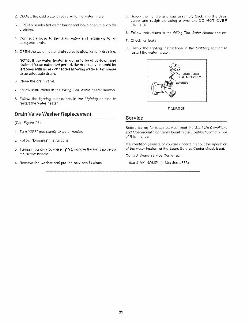
Burner Inspection
Flood damage to a water heater may not be readily visible or
immediately detectable. However, over a period of time a
flooded water heater will create dangerous conditions whichcan cause DEATH, SERIOUS BODILY INJURY, OR PROPERTYDAMAGE. Contact a Sears Service Center to replace a flooded
water heater. Do not attempt to repair the unit! It must be
replaced!
At least once a year a visual inspection should be made of the
main burner and pilot burner, see Figure 23.
You should check for sooting. Soot is not normal and will
impair proper combustion.
Soot build-up indicates a problem that requires correctionbefore further use. Turn 'OFF" gas to water heater and
leave off until repairs are made, because failure to correct thecause of the sooting can result in a fire causing death, serious
injury, or property damage.
FIGURE23.
Burner C_eaning
At least once a year a visual inspection should be made of the
venting system. You should look for:
Obstructions which could cause improper venting. Thecombustion and ventilation air flow must not be obstructed.
Damage or deterioration which could cause improper
venting or leakage of combustion products.
Rusted flakes around top of water heater.
Be sure the vent piping is properly connected to prevent escape
of dangerous flue gasses which could cause deadly
asphyxiation.
Obstructions and deteriorated vent systems may present
serious health risk or asphyxiation.
Chemical vapor corrosion of the flue and vent system may
occur if air for combustion contains certain chemical vapors.
Spray can propellants, cleaning solvents, refrigerator and airconditioner refrigerants, swimming poo! chemicals, calcium
and sodium chloride, waxes, bleach and process chemicals
are typical compounds which are potentially corrosive.
If when inspecting the vent system you find sooting or
deterioration, something is wrong_ Call the local gas supplier
to correct the problem and clean or replace the flue and venting
before resuming operation of the water heater.
Fire or Explosion Hazard
Failure to properly reseal the combustion chamber willdisable the flammable vapor ignition resistance featureof this water heater, which could result in death or seriousinjury Contact your local Sears Service Centerfor assistance
Read instruction manual before
installing, using or serwcmgwater heater,
2O
In the event your burner needs cleaning, following theseinstructions:
If inspection of the burner shows that cleaning is required, turn
the gas control knob clockwise ( r'_ ) to the 'OFF" position,depressing slightly.
NOTE: The knob cannot be turned from "PmLOT" to "OFF"
unless knob is depressed siightmy. DO NOT FORCE.
The burner needs to be removed for cleaning. Cal! the SearsService Center to remove and clean the burner and correct the
problem that required the burner to be cleaned.
Housekeeping
Vacuum around base of water heater for dust, dirt, and lint on a
regular basis.
Fire and Explosion Hazard
Temperature-Pressure Relief Valve Operation
The temperature-pressure relief valve must be manually
operated at bast once a year.
\ ° Do not obstruct combustion airopenings at the bottom of thewater heater.
Do not use or store flammablevapor products such as gasoline,solvents or adhesives in thesarne room or area near waterheater or other appliance
- Visibly inspect air intake screenat least once every six monthsand clean if accumulated lint.
, Can cause serious in}ury ordeath
INSTALLED IN SUITABLE AREA: To insure sufficient ventilation
and combustion air supply, proper clearances from the waterheater must be maintained. See Facts to Consider About the
Location section. Combustible materials such as clothing,
cleaning materials, or flammable liquids, etc. must not be
placed against or adjacent to the water heater because theycould catch on fire.
Anode Rod _nspection
Property Damage Hazard
° Avoid water heater damage.
, Inspection and replacement of anode rod required.
, Burn hazard
, Hotwater discharge.
° Keep dear of relief valvedischarge outlet.
When checking the temperature-pressure relief valve operation,
make sure that (1) no one is in front of or around the outlet ofthe temperature-pressure relief valve discharge line, and
(2) that the water discharge will not cause any property damage,
as the water may be extremely hot, see Figure 24.
TEMPERATURE-PRESSURE
DISCHARGE PiPE
HGURE 24.
If after manually operating the valve, it fails to completely resetand continues to release water, immediately close the cold
water inlet to the water heater, follow the draining instructions,
and replace the temperature-pressure relief valve with a newone.
If the temperature-pressure relief valve on the appliance weeps
or discharges periodically, this may be due to thermal
expansion. You may have a check valve installed in the waterline or a water meter with a check valve. Consult the Sears
Service Center for further information. Do not plug thetemperature-pressure relief valve.
Draining
The anode rod is used to protect the tank from corrosion. Most
hot water tanks are equipped with an anode rod. The
submerged rod deteriorates to protect the tank. Instead ofcorroding the tank, water ions attack and eat away the anoderod. This does not affect the water's taste or color. The rod
must be maintained to keep the tank in operating condition.
Anode deterioration depends on water conductivity, notnecessarily water condition_ A corroded or pitted anode rod
indicates high water conductivity and should be checked and/
or replaced more often than an anode rod that appears to be
intact. Replacement of a depleted anode rod can extend the
life of your water heater. Inspection should be conducted bycalling the Sears Service Center for an authorized contractor. At
a minimum, the anode(s) should be checked annually after
the warranty period.
Burn hazard
o Hotwater discharge.
o Keep hands dear of drainvalve discharge.
21
The water heater should be drained if being shut down during
freezing temperatures. Also periodic draining and cleaning ofsediment from the tank may be necessary.
1. Turn the gas control knob to the "OFF" position.
2. CLOSEthecoldwaterinletvalvetothewaterheater.
3. OPENanearbyhotwaterfaucetandleaveopentoallowfordraining.
4. Connecta hoseto thedrainvalveandterminateto anadequatedrain.
5. OPENthewaterheaterdrainvalvetoallowfortankdraining.
NOTE:If thewaterheaterisgoingto beshutdownanddrainedforanextendedperiod,thedrainvalveshouldbeleftopenwithhoseconnectedallowingwatertoterminatetoanadequatedrain.
6. Closethedrainvalve.
7. FollowinstructionsintheFilling The Water heater section.
8. Follow the lighting instructions in the Lighting section torestart the water heater.
Drain Valve Washer Repmacement
(See Figure 25)
1. Turn "OFF" gas supply to water heater.
2. Follow "Draining" instructions.
3. Turning counter clockwise ( _ ), remove the hex cap belowthe screw handle.
4. Remove the washer and put the new one in place.
5. Screw the handle and cap assembly back into the drain
valve and retighten using a wrench. DO NOT OVERTIGHTEN.
6. Follow instructions in the FiihtTg The Water Heater section.
7. Check for leaks.
8. Follow the lighting instructions in the Lighting section torestart the water heater.
_HANDLEAND
CAP ASSEMBLY%
WASHER
FIGURE 25.
Service
Before calling for repair service, read the Start Up Conditions
and Operational Conditions found in the Troubleshooting Guideof this manual.
If a condition persists or you are uncertain about the operationof the water heater, let the Sears Service Center check it out.
Contact Sears Service Center at:
1-800o4-MyoHOME _'_(1o800o469o4663),
22
Start Up Conditions
Thermal Expansion
Property Damage Hazard
- Avoid water heater damage.
o Install therm'nal expansion tank or device if necessary.
• Contact qualified installer or service agency.
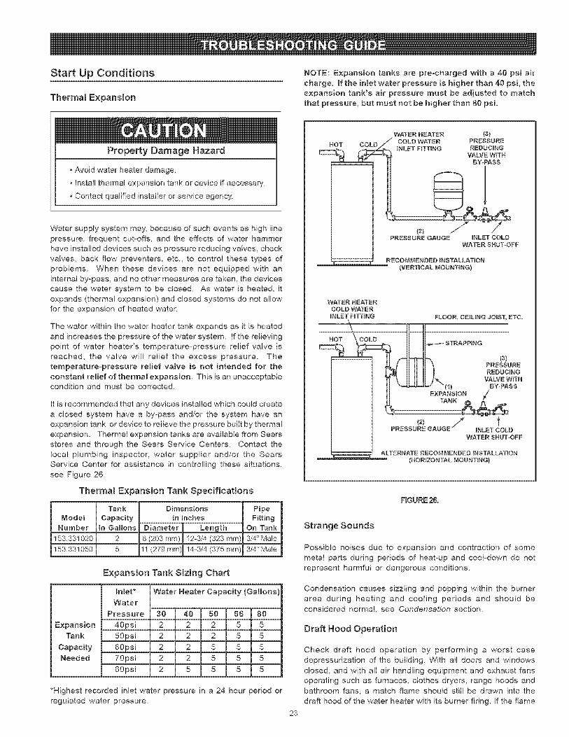
NOTE: Expansion tanks are preocharged with a 40 psi air
charge, mfthe intact water pressure is higher than 40 psi, theexpansion tank's air pressure must be adjusted to match
that pressure, but must not be higher than 80 psi.
Water supply system may, because of such events as high line
pressure, frequent cut-offs, and the effects of water hammerhave installed devices such as pressure reducing valves, check
valves, back flow preventers, etc., to control these types of
problems. When these devices are not equipped with an
internal by-pass, and no other measures are taken, the devices
cause the water system to be closed. As water is heated, it
expands (thermal expansion) and closed systems do not allowfor the expansion of heated water.
The water within the water heater tank expands as it is heated
and increases the pressure of the water system. If the relievingpoint of water heater's temperature-pressure relief valve is
reached, the valve will relief the excess pressure. The
temperature-pressure relief valve is not intended for the
constant relief of thermal expansion, This is an unacceptablecondition and must be corrected.
It is recommended that any devices installed which could create
a closed system have a by-pass and/or the system have an
expansion tank or device to relieve the pressure built by thermal
expansion. Thermal expansion tanks are available from Sears
stores and through the Sears Service Centers. Contact the
local plumbing inspector, water supplier and/or the SearsService Center for assistance in controlling these situations,
see Figure 26.
Therma! Expansion Tank Specifications
Tank Dimensions
Mode_ Capacity in Inches
Number iln Gallons Diameter Length
153.331020 2 8 (203 ram) 12-3/4 (323 mm)
153.331050 5 11 (279 mm) 14-3/4 (375 mm)
PipeFitting
On Tank
3/4" Mate
3/4" Mate
Expansion Tank Sizing Chart
Water Heater Capacity (Gallons)h[et*
Water
Pressure
40psi
50psi
60psi70psi
80psi
30 40 50 66 80
Expansion 2 2 2 5 5Tank 2 2 2 5 5
Capacity 2 2 5 5 5Needed 2 2 5 5 5
2 5 5 5 5
WATER HEATER (3)
(VERTICAL MOUNTING)
WATER HEATERCOLD WATER
INLET HTTING
HOT COLD
FLOOR, CEILING JOBST, ETC,
(3)PRESSURE
REDUCINGVALVE WITH
(1_ BY-PASSEXPANSION /"
TANK :_
tINLETCOLD
WATERSHUT=OFF
ALTERNATE RECOMMENDED INSTALLATION(HORIZONTAL MOUNTING)
F_GURE2&
Strange Sounds
Possible noises due to expansion and contraction of some
metal parts during periods of heat-up and cool-down do not
represent harmful or dangerous conditions.
Condensation causes sizzling and popping within the burnerarea during heating and cooling periods and should be
considered normal, see Condensation section.
Draft Hood Operation
Check draft hood operation by performing a worst case
depressurization of the building. With all doors and windows
closed, and with all air handling equipment and exhaust fansoperating such as furnaces, clothes dryers, range hoods and
bathroom fans, a match flame should still be drawn into the
draft hood of the water heater with its burner firing. If the flame
*Highest recorded inlet water pressure in a 24 hour period or
regulated water pressure.
23
isnotdrawntowardthedrafthood,shutoffwaterheaterandmakenecessaryairsupplychangestocorrect.
Condensation
Whenever the water heater is filled with cold water, some
condensate wil! form while the burner is on. A water heater
may appear to be leaking when in fact the water is condensation.
This usually happens when:
• A new water heater is filled with cold water for the first time.
Burning gas produces water vapor In water heaters,
particularly high efficiency models where flue temperaturesare lower.
Large amounts of hot water are used in a short time and the
refill water in the tank is very cold.
Moisture from the products of combustion condense on the
cooler tank surfaces and form drops of water which may fall
onto the burner or other hot surfaces to produce a "sizzling" or
'frying" noise.
Excessive condensation can cause pilot outage due to water
running down the flue tube onto the main burner and putting
out the pilot.
Because of the suddenness and amount of water,
condensation water may be diagnosed as a 'tank leak'L After
the water in the tank warms up (about 1-2 hours), the condition
should disappear.
Do not assume the water heater is leaking until there has
been enough time for the water in the tank to warm up.
An undersized water heater will cause more condensation.
The water heater must be sized properly to meet the family's
demands for hot water including dishwashers, washingmachines and shower heads.
from hydrogen sulfide gas dissolved in the waten The smell isthe result of four factors which must al! be present for the odor
to develop:
a concentration of sulfate in the supply water.
little or no dissolved oxygen in the water.
a sulfate reducing bacteria within the water heater. (This
harmless bacteria is non4oxic to humans.)
an excess of active hydrogen in the tank. This is caused bythe corrosion protective action of the anode.
Smelly water may be eliminated or reduced in some waterheater models by replacing the anode(s) with one of less activematerial, and then chlorinating the water heater tank and al!hot water lines. Contact Sears Service for further information
concerning an Anode Replacement Kit #9001453 and thisChlorination Treatment. Anode replacement and chlorinationof the tank are not covered by the water heater's limited warranty.
if the smelly water persists after the anode replacement andchlorination treatment, it may be necessary to chlorinate or
aerate your water supply to eliminate the problem.
Do not remove the anode leaving the tank unprotected, By
doing so, all warranty on the water heater tank is voided.
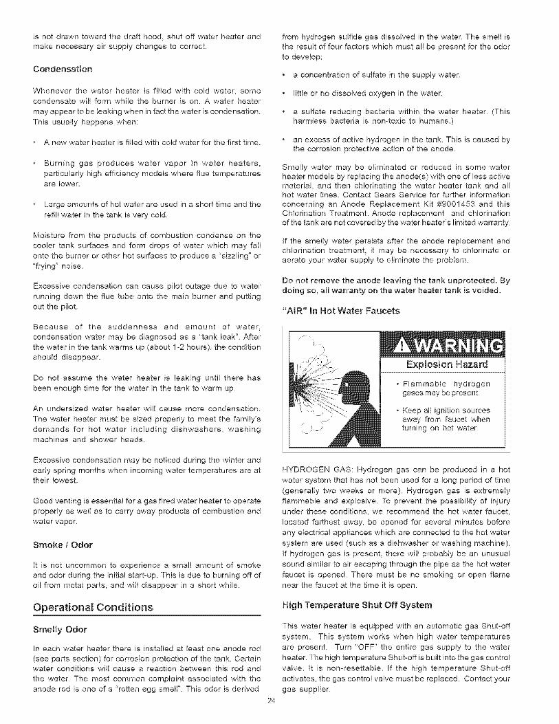
"AIR" In Hot Water Faucets
'}. •
)
Explosion Hazard
, Flammable hydrogengases may be present.
Keep all ignition sourcesaway from faucet whenturning on hot water
Excessive condensation may be noticed during the winter and
early spring months when incoming water temperatures are attheir lowest.
Good venting is essential for a gas fired water heater to operate
properly as well as to carry away products of combustion and
water vapor.
Smoke / Odor
It is not uncommon to experience a small amount of smoke
and odor during the initial start-up. This is due to burning off of
oil from metal parts, and will disappear in a short while.
Operational Conditions
Smelly Odor
In each water heater there is installed at least one anode rod
(see parts section) for corrosion protection of the tank. Certainwater conditions will cause a reaction between this rod and
the waten The most common complaint associated with the
anode rod is one of a 'rotten egg smell". This odor is derived
HYDROGEN GAS: Hydrogen gas can be produced in a hot
water system that has not been used for a long period of time
(generally two weeks or more). Hydrogen gas is extremely
flammable and explosive. To prevent the possibility of injury
under these conditions, we recommend the hot water faucet,
located farthest away, be opened for several minutes before
any electrical appliances which are connected to the hot water
system are used (such as a dishwasher or washing machine).
if hydrogen gas is present, there will probably be an unusual
sound similar to air escaping through the pipe as the hot water
faucet is opened, There must be no smoking or open flame
near the faucet at the time it is open.
Hig h Temperature Shut Off System
24
This water heater is equipped with an automatic gas Shutooff
system. This system works when high water temperatures
are present. Turn 'OFF" the entire gas supply to the water
heater. The high temperature Shutooff is built into the gas control
valve. It is nomresettable. If the high temperature Shutooff
activates, the gas control valve must be replaced. Contact your
gas supplier.
Operational Conditions (Continued)
Leakage Checkpoints
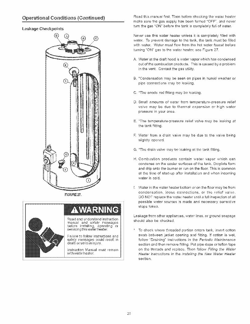
FIGURE27.
Read and understand instructionmanual and safety messagesbefore installing, operating orsewicing this water heater,
Failure to follow instructions andsafety' messages could result indeath or serious injury
Instruction Manual must remainwith water heater
Read this manual first. Then before checking the water heater
make sure the gas supply has been turned 'OFF", and never
turn the gas 'ON" before the tank is completely full of water.
Never use this water heater unless it is completely filled with
water. To prevent damage to the tank, the tank must be filledwith water. Water must flow from the hot water faucet before
turning "ON" gas to the water heater, see Figure 27.
A Water at the draft hood is water vapor which has condensed
out of the combustion products. This is caused by a problem
in the vent. Contact the gas utility.
B. *Condensation may be seen on pipes in humid weather or
pipe connections may be leaking.
C. *The anode rod fitting may be leaking.
D. Small amounts of water from temperatureopressure relief
valve may be due to thermal expansion or high water
pressure in your area.
E. *The temperature-pressure relief valve may be leaking at
the tank fitting.
R Water from a drain valve may be due to the valve being
slightly opened.
G. *The drain valve may be leaking at the tank fitting.
m_ Combustion products contain water vapor which can
condense on the cooler surfaces of the tank. Droplets form
and drip onto the burner or run on the floor. This is common
at the time of start-up after installation and when incomingwater is cold.
Water in the water heater bottom or on the floor may be from
condensation, loose connections, or the relief valve.
DO NOT replace the water heater until a full inspection of all
possible water sources is made and necessary corrective
steps taken.
Leakage from other appliances, water lines, or ground seepage
should also be checked.
To check where threaded portion enters tank, insert cotton
swab between jacket opening and fitting. If cotton is wet,
fo!low 'Draining" instructions in the Periodic Maintenance
section and then remove fitting. Put pipe dope or teflon tape
on the threads and replace. Then follow Fifling the Water
Heater instructions in the instah'ing the New Water Heatersection.
25
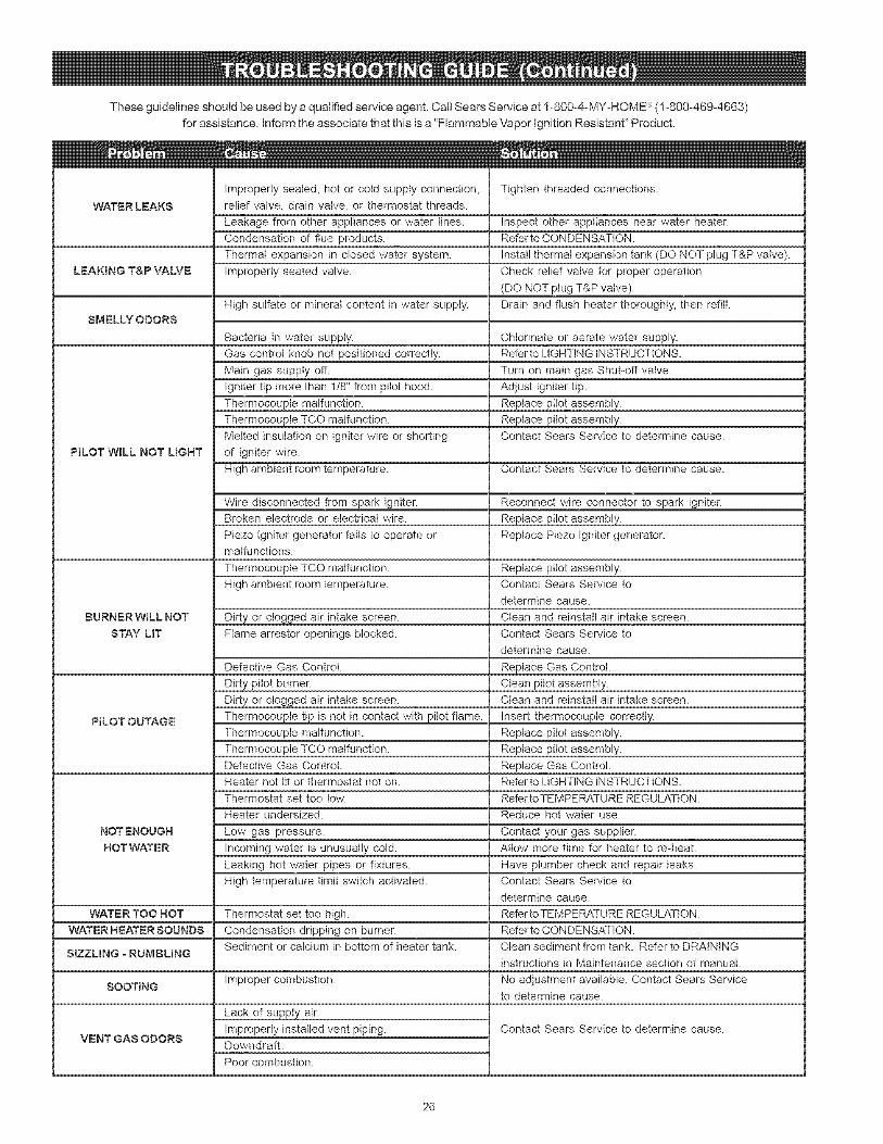
Theseguidelinesshouldbeusedbyaqualifiedserviceagent.CallSearsServiceat1-800o4oMYoHOME_)(!o800-469-4663)forassistance,informtheassociatethatthisisa"FlammableVaporignitionResistant"Product.
WATERLEAKS
LEAKINGT&PVALVE
SMELLYODORS
PILOT WILL NOT L_GHT
BURNER WILL NOT
STAY UT
PILOT OUTAGE
NOT ENOUGH
HOT WATE R
WATER TOO HOT
WATER HEATER SOUNDS
StZZLING o RUMBLBNG
SOOTING
VENTGASODORS
Improperly sealed, hot or cold supply connection,
relief valve, drain valve, or thermostat threads.
Leakage from other appliances or water lines.
Condensation of flue products.
Thermal expansion in closed water system.
Improperly seated valve.
High sulfate or mineral content in water supply.
Bacteria in water suppty.
Gas controt knob not positioned correctly.
Main gas suppty off.
Igniter tip more than 1/8" from pilot hood.
Thermocouple malfunction.
Thermocouple TCO malfunction.
Melted insulation on igniter wire or shorting
of igniter wire.
High ambient room temperature.
Wire disconnected from spark igniter.Broken electrode or electrical wire.
Piezo tgniter generator fails to operate ormalfunctions.
Thermocouple TCO malfunction.
High ambient room temperature.
Dirty or ctogged air intake screen.Flame arrestor openings blocked.
Defective Gas Control.
Dirty pilot burner.
Dirty or clogged air intake screen.
Thermocouple tip is not in contact with pilot flame.
Thermocouple malfunction.
Thermocouple TCO malfunction.Defective Gas Control.
Heater not tit or thermostat not on.
Thermostat set too low.
Heater undersized.
Low gas pressure.
Incoming water is unusually cold.
Leaking hot water pipes or fixtures.
High temperature limit switch activated.
Thermostat set too high.
Condensation dripping on burner.Sediment or calcium in bottom of heater tank.
Improper combustion.
Lack of supply air.
Improperly installed vent piping.Downdraft.
Poor combustion.
Tighten threaded connections.
Inspect other appliances near water heater.Refer to CONDENSATION.
install thermal expansion tank (DO NOT plug T&P valve).
Check relief valve for proper operation
(DO NOT plug T&P valve).
Drain and flush heater thoroughly, then refill.
Chlorinate or aerate water supply.Refer to LIGHTING iNSTRUCTIONS.
Turn on main gas Shut-off valve.
Adjust igniter tip.
Replace pilot assembly.
Reptace pilot assembly.Contact Sears Service to determine cause.
Contact Sears Service to determine cause.
Reconnect wire connector to spark igniter.
Replace pilot assembly.
Replace Piezo Igniter generator.
Reptace pilot assembly.Contact Sears Service to
determine cause.
Ctean and reinstall air intake screen.
Contact Sears Service to
determine cause.
Replace Gas Control.Clean pilot assembly.Clean and reinstall air intake screen.
Insert thermocoupte correctly.
Replace pitot assembly.
Replace pilot assembly.
Replace Gas Control.Refer to LIGHTING INSTRUCTIONS.
Refer to TEMPERATURE REGULATtON.
Reduce hot water use.
Contact your gas supplier.Allow more time for heater to re-heat.
Have plumber check and repair leaks.Contact Sears Service to
determine cause.
Refer to TEMPER_,TURE REGULATION.
Refer to CONDENSATION.
Clean sediment from tank. Refer to DRAINtNG
instructions in Maintenance section of manual.
No adjustment available. Contact Sears Serviceto determine cause.
Contact Sears Service to determine cause.
26
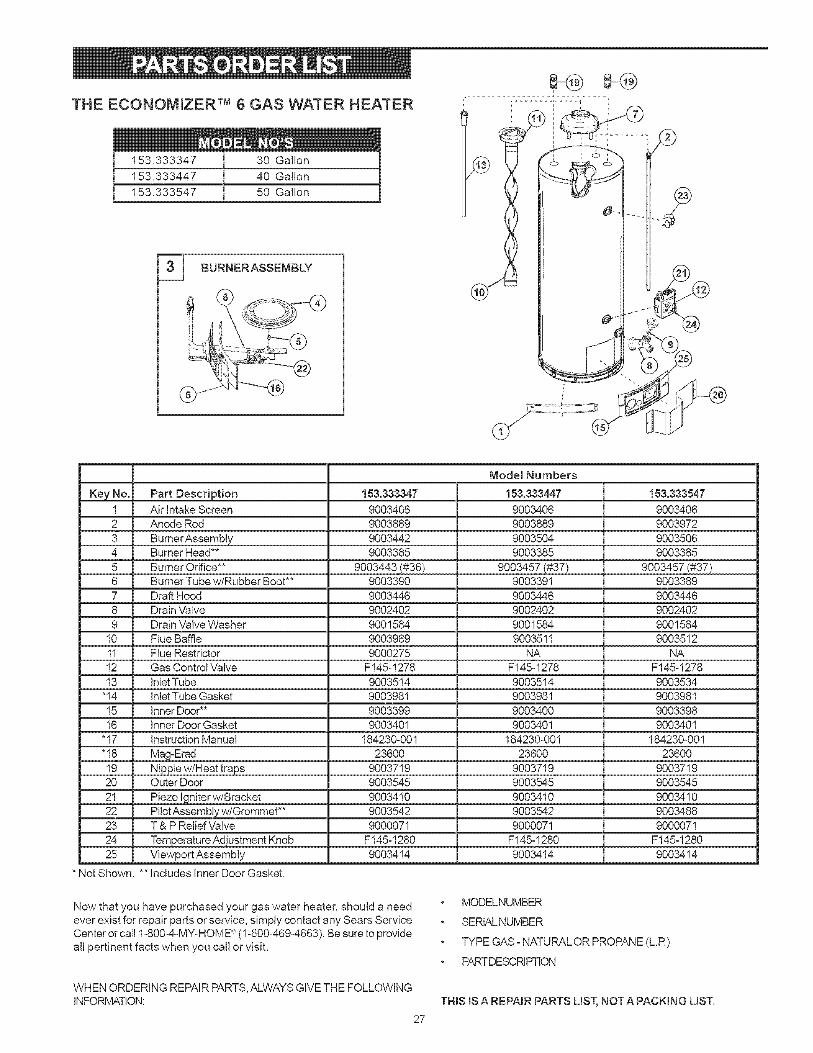
THE ECONOMIZER TM 6 GAS WATER HEATER
153.333347 30 Gallon
153.333447 40 Gallon
153.333547 50 Gallon
BURNERASSEMBLY
[ .... i...... 7
Key No. Part Description
1 Air Intake Screen2 Anode Rod
3 BurnerAssembly4 Burner Head**
5 Burner Orifice**6 Burner Tube w/Rubber Boot**
7 Draft Hood
8 Drain Valve
9 Drain Valve Washer
10 Flue Baffle
11 Flue Restrictor12 Gas Control Valve
13 InletTube
"14 Inlet Tube Gasket
15 Inner Door**16 Inner Door Gasket
"17 Instruction Manual
"18 Ma_-Erad
19 Nipple w/Heat traps20 Outer Door
21 Piezo Igniter w/Bracket
22 Pilot Assembly w/Grommet**23 T & P Relief Valve
24 Temperature Adiustment Knob25 Viewport Assembly
153.333347
90034069003889
9003442
9003385
9003443 (#86)
Model Numbers
153.333447
90034069003889
9003504
9003385
9003457 (#37)
153.333547
90034069003972
9003506
9003385
9003457 (#37)9003390
9003446
9002402
9001584
9003969
9000275F145-1278
9003514
9003981
90033999003401
184230-001
23600
9003719
9003545
90034109003542
9000071
F145-1280
9003414
9003391
9003446
9002402
9001584
9003511
NAF145-1278
9003514
9003981
9003400
9003401
184230-001
23600
9003719
9003545
90034109003542
9000071
F145-1280
9003414
9003389
9003446
9002402
9001554
9003512
NAF145-1278
9003534
9003981
90033989003401
184230-001
23600
9003719
9003545
90034109003488
9000071
F145-1280
9003414
* Not Shown. ** Includes Inner Door Gasket.
Now that you have purchased your gas water heater, should a needever exist for repair parts or service, simply contact any Sears ServiceCenter or call 1-8004-MY_HOME _ (1-800-469o4663). Be sure to provideall pertinent facts when you call or visit.
WHEN ORDERING REPAIR PARTS, ALWAYS GIVE THE FOLLOWINGINFORMATION:
27
MODELNUMBER
SERIALNUMBER
TYPE GAS-NATURALOR PROPANE(LR)
PARTDESCRIPTION
THINSIS A REPAmR PARTS UST, NOT A PACKmNG LIST.
6 YEAR LIMITED WARRANTY ON WATER HEATER
For six years from date of purchase, if this water heater is installed and operated in a single-family home in accordance with theowner's manual instructions and all local applicable plumbing codes, Sears will supply a free water heater for one that developsa leak.
For the second through sixth year from purchase date, you must pay the labor cost for installation of water heater.
For commercial, institutional, industrial, or residential use by two or more families, the above limited warranty is only for two years.During the second year you must pay the labor cost for water heater installation.
1 YEAR EXCLUSIVE KENMORE LABOR WARRANTY
For the first year from the date of purchase, Sears will, free of charge, supply and install new water heater parts for defectiveones or a new water heater for one that develops a leak.
WARRANTY SERVICE
To obtain warranty service, call 1-800-4-MY-HOME _ (!-800-469-4663). This warranty applies only while this product is in use in theUnited States.
This warranty gives you specific legal rights and you may also have other rights which vary from state to state.
SEARS, ROEBUCK AND CO., Dept. 817 WA, HOFFMAN ESTATES, IL 60179
The price of your water heater does not include a free checkup service call. On water heater installations arranged by Sears, Searswarrants the installation.
A charge will be made on service calls due to poor or incomplete installation. These include:a. Adjusting thermostat b. Leaks in pipes or fittings c. Condensation
MASTERPROTECTIONAGREEMENTS
Congratulations on making a smart purchase. Your new Kenmord R'
product is designed and manufactured for years of dependableoperation. But like all products, it may require preventive maintenanceor repair from time to time. That's when having a Master ProtectionAgreement can save you money and aggravation.
Purchase a Master Protection Agreement now and protect yourself
from unexpected hassle and expense.
The Master Protection Agreement also helps extend the life of yournew product. Here's what's included in the Agreement:
Expert Service by our 12,000 professional repair specialists.
Unlimited service and no charge for parts and labor on allcovered repairs.
"No-lemon" guarantee - replacement of your covered product iffour or more product failures occur within twelve months.
Product replacement if your covered product can't be fixed.
Annual Preventive Maintenance Check at your request - noextra charge.
Fast help by phone - phone support from a Sears technician on
products requiring in-home repair, plus convenient repair scheduling.
Power surge protection against electrical damage due to powerfluctuations.
Rental reimbursement if repair of your covered product takeslonger than promised.
Once you purchase the Agreement, a simple phone call is all that ittakes for you to schedule service. You can call anytime day or night, orschedule a service appointment on-line.
Sears has over !2,000 professional repair specialist, who have accessto over 4.5 million quality parts and accessories. That's the kind of
professionalism you can count on to help prolong the life of your newpurchase for years to come. Purchase your Master ProtectionAgreement today!
Some [imitations and exclusions apply. For prices andadditional information cal_ 1o800o827o6655.
SEARS INSTALLATION SERWCE
For Sears professional installation of home appliances, garage dooropeners, water heaters and other major home items, in the U.S.A., call1-800-4-M%HOME "_.
For in-home major brand repair serviceCall 24 hours a day, 7 days a week (U.S.A. and Canada)
IoS00o4oMYoHOME ®(1-800=469-4663)
www.sears.com
The model number of your water heater is found on the model rating plate on the front of the water heater
Sears, Roebuck and Co., Hoffman Estates, IL 60t79 U.S.A.