Embed Size (px)
Citation preview
Association of Metallurgical Engineers of Serbia AMES
Scientific paper UDC: 669.322.046.58
THE EFFECT OF COOLING RATE OF SLAG FROM PRIMARY COPPER PRODUCTION IN THE VALORIZATION OF COPPER
IN THE FLOTATION PROCESS
Aleksandar Mihajlović1, Željko Kamberović2, Marija Korać2, Milorad Gavrilovski1, Nikola Jovanović1
1Innovation Center of the Faculty of Technology and Metallurgy, University of Belgrade, Karnegijeva 4, Belgrade, Serbia
2Faculty of Technology and Metallurgy, University of Belgrade, Karnegijeva 4, Belgrade, Serbia
Received 29.01.2015 Accepted 04.05.2015
Abstract Technological procedure of slow cooling slag from primary copper production is
applied in the purpose of copper recovery in the level of 98.5% to blister. This technological procedure is divided into two phases, first slow cooling of
slag on the air for 24 hours, and then accelerated cooling with water for 48 hours. Within the research following methods were used: calculation of nonstationary
slag cooling, verification of the calculation using computer simulation of slag cooling in the software package COMSOL Multiphysics and experimental verification of simulation results.
After testing of the experimentally gained samples of slowly cooled slag it was found that this technological procedure gives the best results in promoting growth or coagulation of dispersed particles of copper sulfide and copper in the slag, thereby increasing the utilization of the flotation process with a decrease of copper losses through very fine particles. Keywords: slag, copper, slow cooling, nonstationary cooling
Introduction In order to modernize the production process in the company RTB Bor, a new,
environmentally friendly, Outotec flesh smelting technology is adopted. The process of copper production from primary raw materials consists of smelting in flash smelting furnace (FSF), converting of matte in Peirce-Smith converters (PSC), anodic and electrolytic refining and production of sulfuric acid from waste gas streams.
128 Metall. Mater. Eng. Vol 21 (2) 2015 p. 127-141
In the production process, during technological operations of melting and converting, liquid slags are obtained. They represent molten oxide with small amounts of sulfides and metallic copper[9].
Slag from smelting contain significantly greater amount of copper than expected in an equilibrium state. Slag from converting, especially from the period of copper blowing, is typically inhomogeneous with significant amounts of suspended matte and metallic copper.
To achieve the technological exploitation of copper in the level of 98.5% to blister in processing concentrate by using autogenous flash smelting technology, it is necessary to process the slag generated in the process of concentrate smelting and converting of matte. Processing of smelting slag in the purpose of its "impoverishment" or better valorization of copper can be done in several ways.
Processing the slag by the scheme of slow cooling-crushing-grinding-flotation in order to obtain flotation concentrate rich in copper is recommended if there is enough space and where there are conditions for adequate treatment of tailings. Also by using the flotation process, the best technological exploitation of copper is achieved, which is very important because the the slag contains up to 6 to 7% of mobile copper.
The cooling metode of slag before flotation may have a significant impact on the achievement of flotation performance. Therefore, it is important to make the proper selection of slag cooling method. One method involves pouring the slag in pits and cooling by spraying slag surface with water. This is traditional method of slag cooling, and it is characterized with low technological exploitation of copper during flotation and impossibility of separating a phase rich in copper before grinding. Other method is slow cooling of slag in pots. This method is characterized with high technological exploitation of copper during flotation and separating a phase rich in copper which is formed at the bottom of the pot .
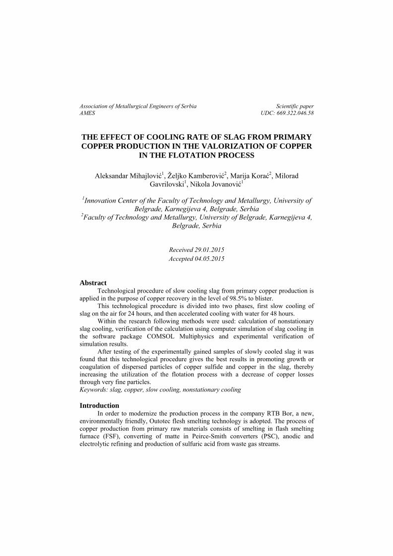
The content of copper in the flotation tailings directly depends on fragmentation rate (Figure 1). Expected content of copper in the flotation tailings, in the case of cooling in pits, is 0.5-0.9%, and in the case of cooling in pots, from 0.22 to 0.35% Cu.
Fig. 1. The effect of fragmentation rate on the slag flotation [6]
Mihajlović - The effect of cooling rate of slag from primary copper production … 129
In Table 1 an overview is given of copper content in flotation tailings in smelters which process slag by flotation.
Table 1. Copper content in flotation tailings in different smelters
Smelter %Cu Almalykskii, Russia 0,27Garfield, USA 0,48 Guixi, China 0,50 Harhavalta, Finland * 0,34 Hayden, USA 0,75 Horne, Canada * 0,41 Isabel, Philippines 0,44 Kosaka, Japan 0,60 Mt. Isa Copper, Australia 0,59 Pirdop, Bulgaria 0,45 Rönnskär (FF), Sweden 0,60 Saganoseki, Japan 0,79 Tamano, Japan 0,84 Toyo, Japan 0,40 Average 0,53
* OUTOTEC facility
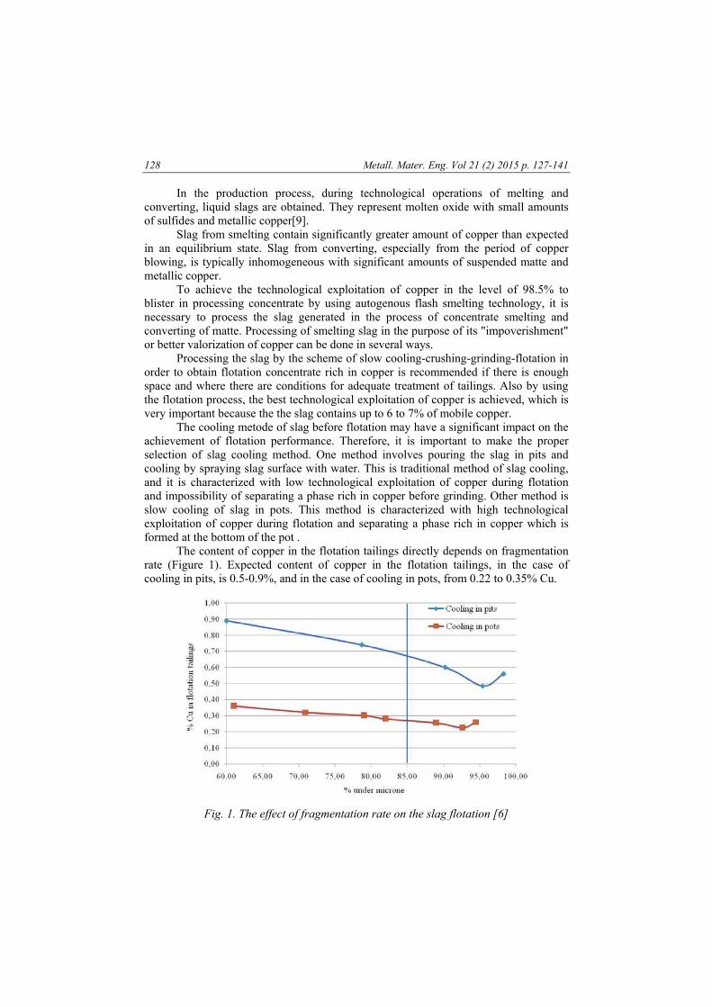
The dependence of the degree of copper recovery by flotation from the cooling
rate is shown in Figure 2. Based on these dependencies shown in Figure 2, it can be concluded that the
slow cooling achieve higher copper recovery. For cooling off period of 24 hours, the level of copper recovery is ~ 86%. After prolonged cooling to 48 hours, copper recovery, in the case of flotation concentrate with 20% copper, may be up to 89%.
Fig. 2. Dependence of the degree of copper recovery by flotation from the cooling rate
130 Metall. Mater. Eng. Vol 21 (2) 2015 p. 127-141
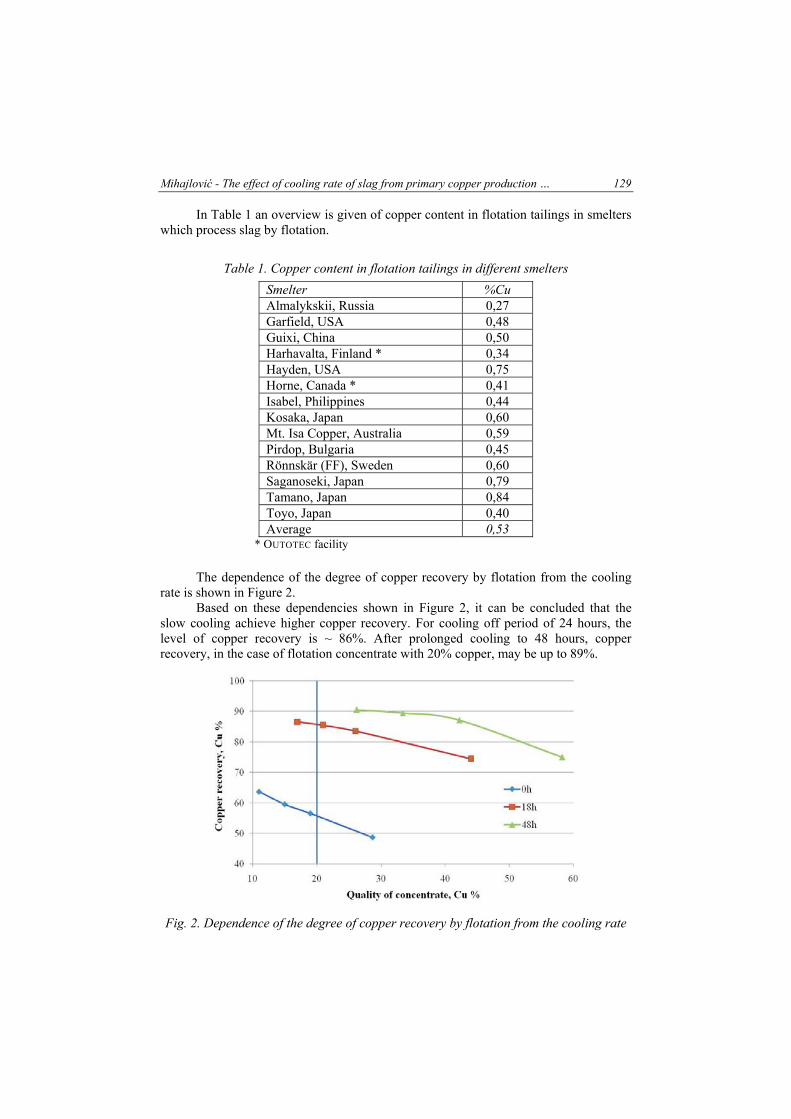
Based on the dependence shown in Figure 3 and the known degree of fragmentation in flotation, efficiency of copper recovery is 89%.
Fig. 3. Efficiency of copper recovery depending on slag fragmentation rate in rough flotation
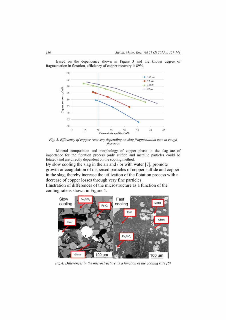
Mineral composition and morphology of copper phase in the slag are of importance for the flotation process (only sulfide and metallic particles could be fotated) and are directly dependent on the cooling method. By slow cooling the slag in the air and / or with water [7], promote growth or coagulation of dispersed particles of copper sulfide and copper in the slag, thereby increase the utilization of the flotation process with a decrease of copper losses through very fine particles. Illustration of differences of the microstructure as a function of the cooling rate is shown in Figure 4.
Fig.4. Differences in the microstructure as a function of the cooling rate [8]
Mihajlović - The effect of cooling rate of slag from primary copper production … 131
During slow cooling of the slag a reaction of copper (I) oxide with the iron occurs according to the reaction (3). With prolongation of cooling, the reaction equilibrium is shifted to the right.
Cu2O(l)+3FeO(l)→2Cu(s)+Fe3O4(s) (1)
Experimental part Calculation of nonstationary slag cooling implies determining the temperature in
the center and on the surface of the slag in the ladle at each stage of cooling (after cooling in the air and after cooling with water).
The process of cooling of slag can be mathematically described using Fourier differential equation of second order.
However, due to the complex geometry of the ladle containing slag and slag properties depending on temperature and time, the analytical solutions to this problem are not possible. Therefore, as an approximation, "Newman's problem" and nomograms system are used, which considers one dimensional final volume of material.
For purposes of the calculation, the following simplifications were used: the upper edge of the ladle is in level with the upper surface of the
molded slag, ie. ladle is filled to its full volume, a ladle consists only of shell, ie. patrs for standing and parts used for
turning the ladle are ignored, slag density is constant during cooling, typical ladle for cooling of slag with volume of 15 m3 for the needs of
calculation is reduced to a short cylinder with diameter of 3 m and height of 2.5 m.
In the calculation of slag cooling following data are used: average temperature of the slag at the beginning of the cooling: Tp =
1290 oC average temperature of the ambient air: To = 20 oC slag density: ρ =3.6 t/m3
heat capacity of slag: cp = 0.70 kJ/kgK effective thermal conductivity of the slag: λef = 15 W/mK effective thermal diffusivity: aef = λef / ρ cp = 6 10-6 m2/s coefficient of convective heat transfer for day 1: α1 ≈ 70 W/m2K coefficient of convective heat transfer for days 2-3: α2-3 ≥ 160 W/m2K cylinder radius: r = 1.5 m Nusselt number: Nu = αr/ λef Fourier number: X (Fo) = aτ/r2
Temperature in slag center: Tc Slag surface temperature: Ts relative temperature in the center: Yc = (Tc –To)/(Tp-To) relative temperature on the surface: Ys = (Ts –To)/(Tp-To)
The effective thermal conductivity of the slag λef, is estimated from the data, that
the basis of slag (fayalite), as the matrix, contains fine particles of copper (1.4 and 6%
132 Metall. Mater. Eng. Vol 21 (2) 2015 p. 127-141
by weight), and the ladle in which the slag is placed is made from steel. The total thermal conductivity of the matrix (fayalite), which is of the order of 1 W/mK, is estimated at 15 W/mK, because of participation of fine particles of copper (λ = 350 W/mK) in the slag, on which a steel shell (λ = 50 W/mK) is continued.
Effective coefficient of convective heat transfer for day 1, α1, contains the portion of natural convection (αair) to ambient air and the portion of radiation (αrad) from hot slag and outer surface of the ladle to the surrounding air, ie:
α1= αair + αrad (2)
It is known that the portion of the radiation in the total convection is significant only over 400 oC.
The degree of blackness of slag surface (ĺs) and the outer surface of the ladle (εl) are approximately equal: εs ≈ εl ≈ 0.8.
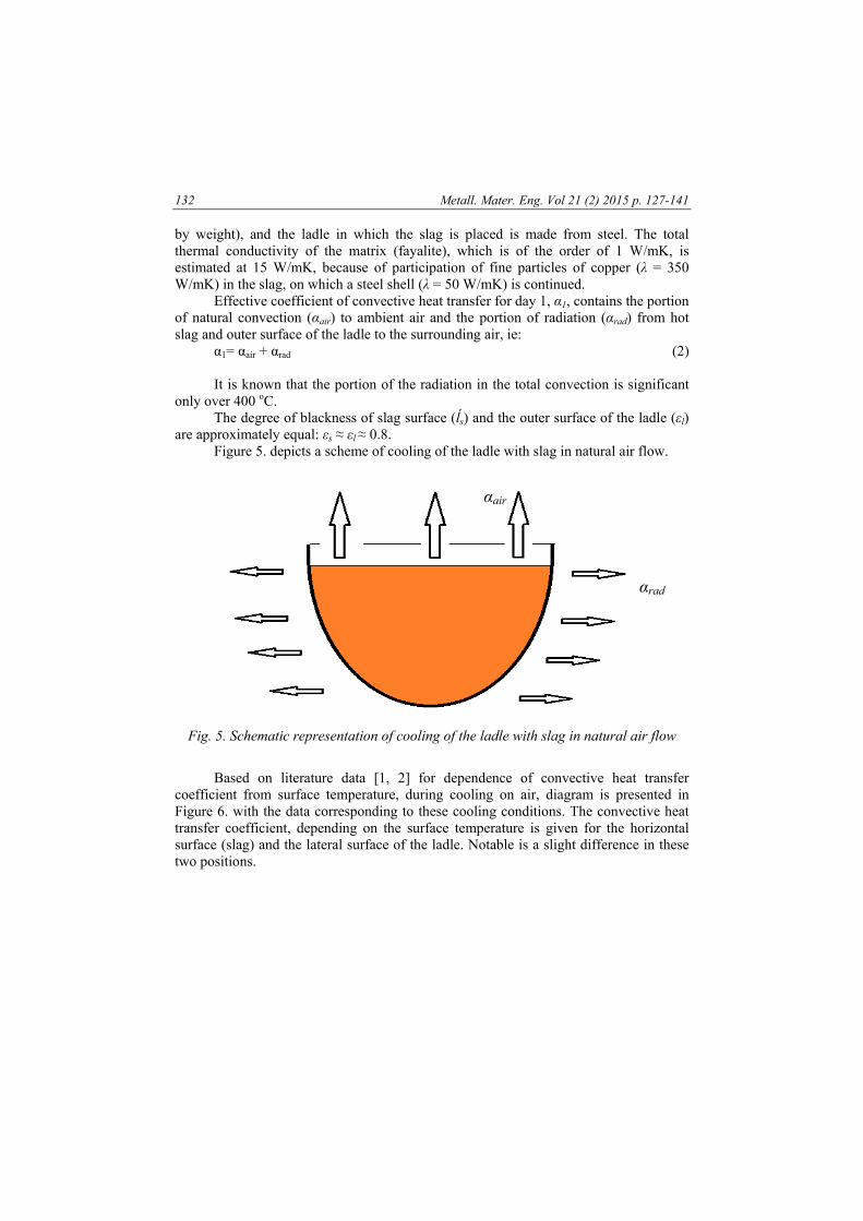
Figure 5. depicts a scheme of cooling of the ladle with slag in natural air flow.
Fig. 5. Schematic representation of cooling of the ladle with slag in natural air flow
Based on literature data [1, 2] for dependence of convective heat transfer
coefficient from surface temperature, during cooling on air, diagram is presented in Figure 6. with the data corresponding to these cooling conditions. The convective heat transfer coefficient, depending on the surface temperature is given for the horizontal surface (slag) and the lateral surface of the ladle. Notable is a slight difference in these two positions.
αair
αrad
Mihajlović - The effect of cooling rate of slag from primary copper production … 133
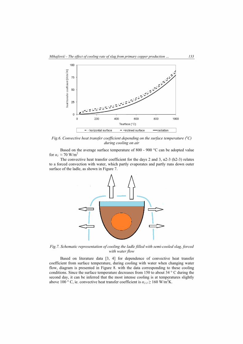
Fig.6. Convective heat transfer coefficient depending on the surface temperature (oC) during cooling on air
Based on the average surface temperature of 800 - 900 °C can be adopted value for α1 ≈ 70 W/m2
The convective heat transfer coefficient for the days 2 and 3, α2-3 (h2-3) relates to a forced convection with water, which partly evaporates and partly runs down outer surface of the ladle, as shown in Figure 7.
Fig.7. Schematic representation of cooling the ladle filled with semi-cooled slag, forced with water flow
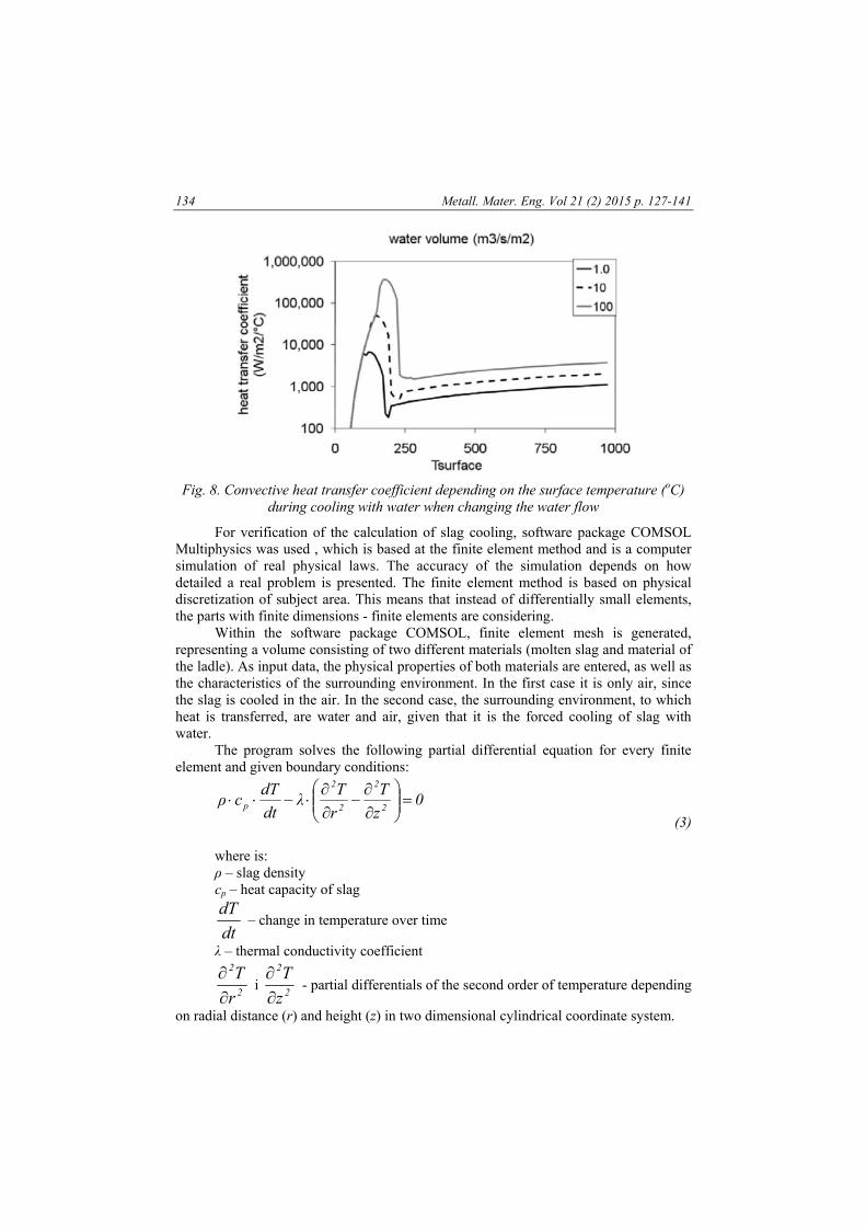
Based on literature data [3, 4] for dependence of convective heat transfer coefficient from surface temperature, during cooling with water when changing water flow, diagram is presented in Figure 8. with the data corresponding to these cooling conditions. Since the surface temperature decreases from 150 to about 34 ° C during the second day, it can be inferred that the most intense cooling is at temperatures slightly above 100 ° C, ie. convective heat transfer coefficient is α2-3 ≥ 160 W/m2K.
134 Metall. Mater. Eng. Vol 21 (2) 2015 p. 127-141
Fig. 8. Convective heat transfer coefficient depending on the surface temperature (oC) during cooling with water when changing the water flow
For verification of the calculation of slag cooling, software package COMSOL Multiphysics was used , which is based at the finite element method and is a computer simulation of real physical laws. The accuracy of the simulation depends on how detailed a real problem is presented. The finite element method is based on physical discretization of subject area. This means that instead of differentially small elements, the parts with finite dimensions - finite elements are considering.
Within the software package COMSOL, finite element mesh is generated, representing a volume consisting of two different materials (molten slag and material of the ladle). As input data, the physical properties of both materials are entered, as well as the characteristics of the surrounding environment. In the first case it is only air, since the slag is cooled in the air. In the second case, the surrounding environment, to which heat is transferred, are water and air, given that it is the forced cooling of slag with water.
The program solves the following partial differential equation for every finite element and given boundary conditions:
0z
T
r
Tλ
dt
dTcρ
2
2
2
2
p
(3)
where is: ρ – slag density cp – heat capacity of slag
dt
dT – change in temperature over time
λ – thermal conductivity coefficient
2
2
r
T
i 2
2
z
T
- partial differentials of the second order of temperature depending
on radial distance (r) and height (z) in two dimensional cylindrical coordinate system.
Mihajlović - The effect of cooling rate of slag from primary copper production … 135
The program requires the definition of initial and boundary conditions of the third kind and defining the heat characteristics of the system. Most problematic are the values of the convective heat transfer coefficient , thermal conductivity, density, viscosity and heat capacity of slag given that they change over time due to changes in aggregate state of the slag over time. Therefore, appropriate approximations are introduced, same as in matematical calculations of slag cooling.
In addition, the slag passes from the liquid to the solid phase, ie. in the onset of cooling the slag is liquid, and at the end it is solid with unknown final structure, which further complicates the calculation of cooling, as the above mentioned values are different in the liquid and solid phase.
As for the convective heat transfer during cooling of slag with water, the problem is that it comes to the appearance of the gas film through which heat is transferred, which further complicates the determination of convective heat transfer coefficient.
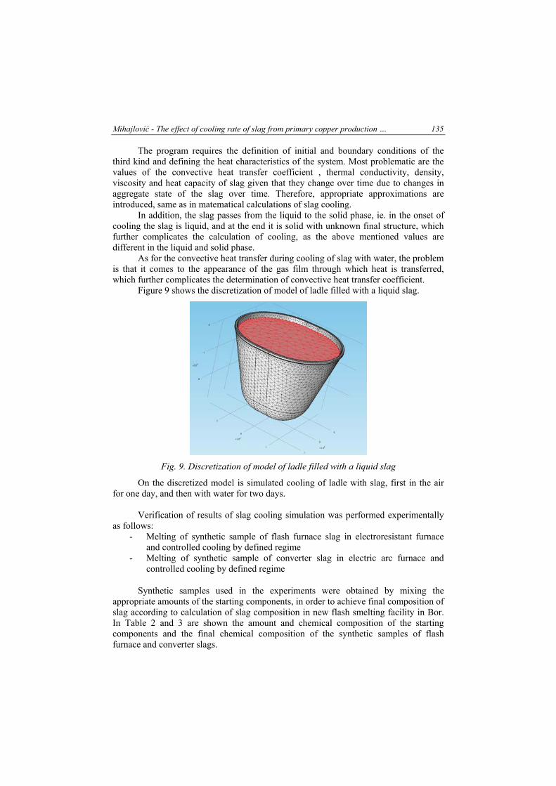
Figure 9 shows the discretization of model of ladle filled with a liquid slag.
Fig. 9. Discretization of model of ladle filled with a liquid slag
On the discretized model is simulated cooling of ladle with slag, first in the air for one day, and then with water for two days.
Verification of results of slag cooling simulation was performed experimentally
as follows: - Melting of synthetic sample of flash furnace slag in electroresistant furnace
and controlled cooling by defined regime - Melting of synthetic sample of converter slag in electric arc furnace and
controlled cooling by defined regime
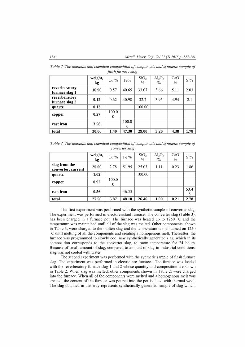
Synthetic samples used in the experiments were obtained by mixing the appropriate amounts of the starting components, in order to achieve final composition of slag according to calculation of slag composition in new flash smelting facility in Bor. In Table 2 and 3 are shown the amount and chemical composition of the starting components and the final chemical composition of the synthetic samples of flash furnace and converter slags.
136 Metall. Mater. Eng. Vol 21 (2) 2015 p. 127-141
Table 2. The amounts and chemical composition of components and synthetic sample of flash furnace slag
weight,
kg Cu % Fe%
SiO2 %
Al2O3 %
CaO %
S %
reverberatory furnace slag 1
16.90 0.57 40.65 33.07 3.66 5.11 2.03
reverberatory furnace slag 2
9.12 0.62 40.98 32.7 3.95 4.94 2.1
quartz 0.13 100.00
copper 0.27 100.0
0
cast iron 3.58 100.0
0
total 30.00 1.40 47.30 29.00 3.26 4.38 1.78
Table 3. The amounts and chemical composition of components and synthetic sample of converter slag
weight,
kg Cu % Fe %
SiO2 %
Al2O3 %
CaO %
S %
slag from the converter, current
25.00 2.78 51.95 25.03 1.11 0.23 1.86
quartz 1.02 100.00
copper 0.92 100.0
0
cast iron 0.56 46.55 53.4
5 total 27.50 5.87 48.18 26.46 1.00 0.21 2.78
The first experiment was performed with the synthetic sample of converter slag.
The experiment was performed in electoresistant furnace. The converter slag (Table 3), has been charged in a furnace pot. The furnace was heated up to 1250 °C and the temperature was maintained until all of the slag was melted. Other components, shown in Table 3, were charged to the molten slag and the temperature is maintained on 1250 °C until melting of all the components and creating a homogenous melt. Thereafter, the furnace was programmed to slowly cool new synthetically generated slag, which in its composition corresponds to the converter slag, to room temperature for 24 hours. Because of small amount of slag, compared to amount of slag in industrial conditions, slag was not cooled with water.
The second experiment was performed with the synthetic sample of flash furnace slag. The experiment was performed in electric arc furnaces. The furnace was loaded with the reverberatory furnace slag 1 and 2 whose quantity and composition are shown in Table 2. When slag was melted, other components shown in Table 2. were charged into the furnace. When all of the components were melted and a homogenous melt was created, the content of the furnace was poured into the pot isolated with thermal wool. The slag obtained in this way represents synthetically generated sample of slag which,
Mihajlović - The effect of cooling rate of slag from primary copper production … 137
by its composition corresponds to the slag from the flash furnace. After pouring, slag was left in the pot to cool for 24 hours.
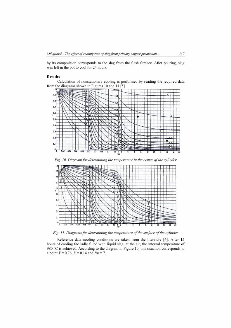
Results Calculation of nonstationary cooling is performed by reading the required data
from the diagrams shown in Figures 10 and 11 [5]
Fig. 10. Diagram for determining the temperature in the center of the cylinder
Fig. 11. Diagrams for determining the temperature of the surface of the cylinder
Reference data cooling conditions are taken from the literature [6]. After 15 hours of cooling the ladle filled with liquid slag, at the air, the internal temperature of 980 °C is achieved. According to the diagram in Figure 10, this situation corresponds to a point Y = 0.76, X = 0.14 and Nu = 7.
138 Metall. Mater. Eng. Vol 21 (2) 2015 p. 127-141
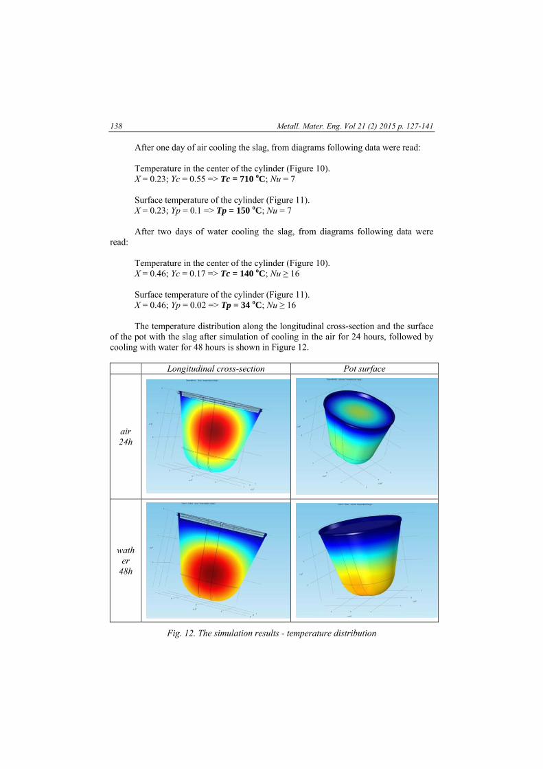
After one day of air cooling the slag, from diagrams following data were read: Temperature in the center of the cylinder (Figure 10). X = 0.23; Yc = 0.55 => Tc = 710 oC; Nu = 7 Surface temperature of the cylinder (Figure 11). X = 0.23; Yp = 0.1 => Tp = 150 oC; Nu = 7 After two days of water cooling the slag, from diagrams following data were
read: Temperature in the center of the cylinder (Figure 10). X = 0.46; Yc = 0.17 => Tc = 140 oC; Nu ≥ 16 Surface temperature of the cylinder (Figure 11). X = 0.46; Yp = 0.02 => Tp = 34 oC; Nu ≥ 16 The temperature distribution along the longitudinal cross-section and the surface
of the pot with the slag after simulation of cooling in the air for 24 hours, followed by cooling with water for 48 hours is shown in Figure 12.
Longitudinal cross-section Pot surface
air 24h
wather
48h
Fig. 12. The simulation results - temperature distribution
Mihajlović - The effect of cooling rate of slag from primary copper production … 139
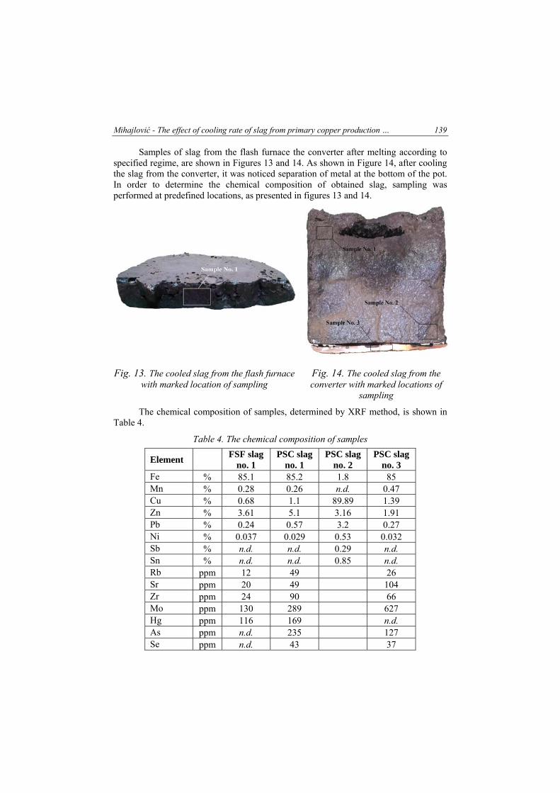
Samples of slag from the flash furnace the converter after melting according to specified regime, are shown in Figures 13 and 14. As shown in Figure 14, after cooling the slag from the converter, it was noticed separation of metal at the bottom of the pot. In order to determine the chemical composition of obtained slag, sampling was performed at predefined locations, as presented in figures 13 and 14.
Fig. 13. The cooled slag from the flash furnace with marked location of sampling
Fig. 14. The cooled slag from the converter with marked locations of
sampling
The chemical composition of samples, determined by XRF method, is shown in Table 4.
Table 4. The chemical composition of samples
Element FSF slag
no. 1 PSC slag
no. 1 PSC slag
no. 2 PSC slag
no. 3 Fe % 85.1 85.2 1.8 85 Mn % 0.28 0.26 n.d. 0.47 Cu % 0.68 1.1 89.89 1.39 Zn % 3.61 5.1 3.16 1.91 Pb % 0.24 0.57 3.2 0.27 Ni % 0.037 0.029 0.53 0.032 Sb % n.d. n.d. 0.29 n.d. Sn % n.d. n.d. 0.85 n.d. Rb ppm 12 49 26 Sr ppm 20 49 104 Zr ppm 24 90 66 Mo ppm 130 289 627 Hg ppm 116 169 n.d. As ppm n.d. 235 127 Se ppm n.d. 43 37
140 Metall. Mater. Eng. Vol 21 (2) 2015 p. 127-141
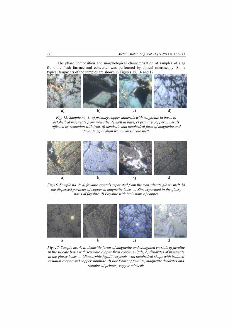
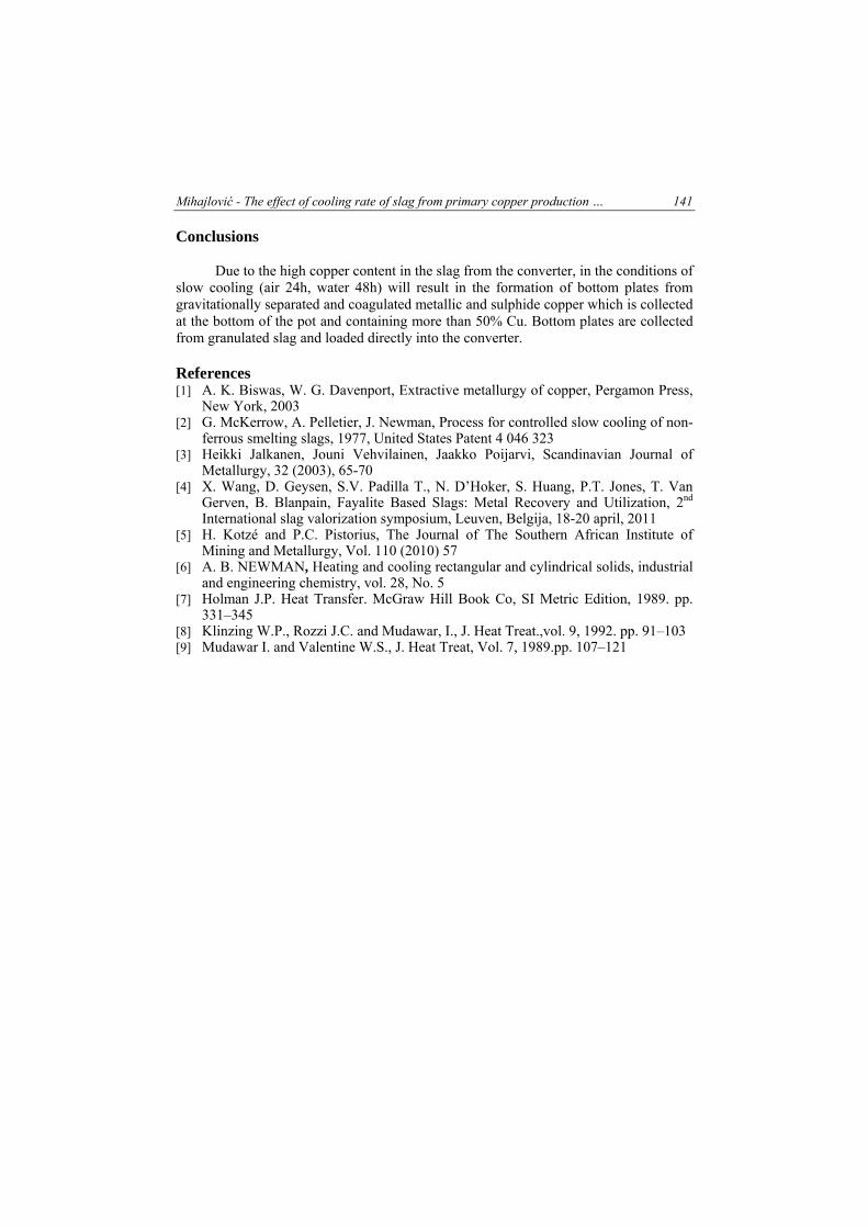
The phase composition and morphological characterization of samples of slag from the flash furnace and converter was performed by optical microscopy. Some typical fragments of the samples are shown in Figures 15, 16 and 17.
a) b) c) d)
Fig. 15. Sample no. 1: a) primary copper minerals with magnetite in base, b) octahedral magnetite from iron silicate melt in base, c) primary copper minerals
affected by reduction with iron, d) dendritic and octahedral form of magnetite and fayalite separation from iron silicate melt
a) b) c) d)
Fig.16. Sample no. 2: a) fayalite crystals separated from the iron silicate glassy melt, b) the dispersed particles of copper in magnetite basis, c) Zinc separated in the glassy
basis of fayalite, d) Fayalite with inclusions of copper
a) b) c) d)
Fig. 17. Sample no. 4: a) dendritic forms of magnetite and elongated crystals of fayalite in the silicate basis with separate copper from copper sulfide, b) dendrites of magnetite in the glassy basis, c) idiomorphic fayalite crystals with octahedral shape with isolated residual copper and copper sulphide, d) Bar forms of fayalite, magnetite dendrites and
remains of primary copper minerals
Mihajlović - The effect of cooling rate of slag from primary copper production … 141
Conclusions Due to the high copper content in the slag from the converter, in the conditions of
slow cooling (air 24h, water 48h) will result in the formation of bottom plates from gravitationally separated and coagulated metallic and sulphide copper which is collected at the bottom of the pot and containing more than 50% Cu. Bottom plates are collected from granulated slag and loaded directly into the converter.
References [1] A. K. Biswas, W. G. Davenport, Extractive metallurgy of copper, Pergamon Press,
New York, 2003 [2] G. McKerrow, A. Pelletier, J. Newman, Process for controlled slow cooling of non-
ferrous smelting slags, 1977, United States Patent 4 046 323 [3] Heikki Jalkanen, Jouni Vehvilainen, Jaakko Poijarvi, Scandinavian Journal of
Metallurgy, 32 (2003), 65-70 [4] X. Wang, D. Geysen, S.V. Padilla T., N. D’Hoker, S. Huang, P.T. Jones, T. Van
Gerven, B. Blanpain, Fayalite Based Slags: Metal Recovery and Utilization, 2nd International slag valorization symposium, Leuven, Belgija, 18-20 april, 2011
[5] H. Kotzé and P.C. Pistorius, The Journal of The Southern African Institute of Mining and Metallurgy, Vol. 110 (2010) 57
[6] A. B. NEWMAN, Heating and cooling rectangular and cylindrical solids, industrial and engineering chemistry, vol. 28, No. 5
[7] Holman J.P. Heat Transfer. McGraw Hill Book Co, SI Metric Edition, 1989. pp. 331–345
[8] Klinzing W.P., Rozzi J.C. and Mudawar, I., J. Heat Treat.,vol. 9, 1992. pp. 91–103 [9] Mudawar I. and Valentine W.S., J. Heat Treat, Vol. 7, 1989.pp. 107–121