Embed Size (px)
Citation preview
4 . b . 11
THE EFFECT OF FLOOR ANO WINO LOAOS
APPLlEO SEPARATELY OR SIMULTANEOUSLY
TO A TWO-STOREY HEIGHT WALL
!~ . ~I • H. \1 =ST
~.R. HODGK I NS ON The British Ceramic Research Association, Stoke - on-Trent, Great BJ'Y':tain
S.A . !i ASE LTl N[
Jenkins & Potter, Consult i ng Engineers, London, Great Britain
THE EFFECT OF FLOOR AND WIND LOADS .4PPLIED
SEPARATELY OR SIMULTANEOUSLY TO A TWO- STOREY
HEIGHT WALL
In the design of two-s tor ey domestic accommodation ex
terna I cavity walls can be re l ied upon to pr ovide
suff icient structur al integrity under almost all con
ditions . It is more di fficult , however, to justify
certain aspects of a single- leaf s tructure in which
the maw-imum thickness through the wall is the half
brick, par ti cular l y where the use of joist hanger s
generates an eccentric loading conditi on .
As a preliminary to the design and construction of 2-
storey single - l eaf masonry dwellings , the tests under
combined f loor and wind loading described herein were
carried out to provide direct measurement of the ulti
mate f ai ling loads . Deflection measurements were made
on the floor and wall , and strain measurements made on
the wall .
Calculations have been made to compare the theoretica l
analysis and the actual measurements .
DIE EINWIRKUNG VON DECKEN- UVD WINDIASTEN
BEl GETRENNTER ODER GLEICHZEITIGER EINLEI
TUNG IN EINE ZWEIGESCHOSSIGE ZIEGELWAND
Beim Entwurf von zweigeschossigen Wohnhiíusem kann
davon ausgegangen we rCkn , dass die ausserun zwei
scha ligen Wiínde mit Luftschicht eine ausruichenCk
Festigkeit unte.r nahezu allen Bedingungen auj'wei
sen o SchwieI'ig dagegen ist es , unteI' den verschie
denen Gesichtspunkten die Fes tigkei t de r einze Znen
SchaZen nachzu,ieisen, die im allgemeinen eine maxi
maZe Dicke von HaZbsteinstiírke haben . Insbesonderu
gi Z t dies , wenn diese durch die Decken Zasten exzen
trisch beZastet werden . Zur Vorbereitung von Ent
wUI'fs - und Konstr uktionsvorschZiígen von zweige
schossigen WohngebiíuCkn wurden Versuche unteI' kom-
binierter Einrúhrung von Decken - und Windlasten
beschrieben und durchgefUhrt, um zu einer Beurlei
Zung der BruchZasten zu kommen. An Ckn Wiinden und
·Decken wurCkn die Durchbiegungen gemessen . Gleich
zei tig wurden die Be lastungen des Mauerwerks e r
mittelt . Danaeh wurCkn VergZeichsrechnungen durch
.gefUhrt, um die theoreti sehen Werte mit den Ver
suchswer ten zu vergZeiehen.
4.b.1 1-Q
L'INFLUENCE DES CHARGES DES PLANCHERS ET DU
VENT APPLIQUEES SEPAREMENT OU SIMULTANEMENT
SUR UN MUR D'UNE lL4UTEUR DE DEUX ETAGES
Dans le projet d'une maison d'habitation à deux étages,
des I11'vl:PS e,'dérieUl's creux donnent une sécu:r>ité struc
turale suffisante dans presque tous les CaB.
Il est cependant plus difficile de justif,:er certaines
cOilstructions à pal'ois simpl3fJ dcns lesquelles l 'épais
seur rraximale du mu.Y' est d'une demi-brique, en parti
cuZier dans les CaB ou la suspension de poutres de
liaison provoque une char·ge excentrique.
Comine préliminaire au caleul et à la roalisation de
parois simples d'une hauteur de deux étages. les
essais combinés des chai'ges de p lanchers et du vent
décr-its ici, ont été exÉcutés afin de déterminer
directement les charges de ruptUl'e. Les flexions du
plancher et du mur ont été mesuroes, ainsi que les
tensions intemes du muro Des calcula ont été faits
pOUl' compare r la théorie aux rosultats du présent
rapport.
HET EFFEKJ! VAN VLOERBELASTING EN WINDLASTEN,
AFZONDERLIJK EN SAME'N OP EEN TWEE
VERDIEPINGSHOGE MUUR.
Voor twee verdiepingen hoge woningen zijn spouw
muren als buitenmuren meestal konstrukties die
voldoende stabiliteit bieden. Het is echter
moeilijker vertrouwen te hebben in konstrukties
bestaande uit muren van slechts een haIve steen
dik, vooral indien baIklagen nog voor een zekere
excentriciteit zorgen.
Als voorbereiding tot het ontwerp en de bouw van
woningen van twee verdiep'ingen, met voUe muren
werden de hierbij beschreven proeven.op vIoer-
en windbeIastingen uitgevoerd, ten einde direkte
meting van de breuklast te bekomen. Vervormings
metingen werden u7:tgevoerd op vloeren en muren.
en op de muren werden ook nog spanningsmetingen
uitgevoerd.
Er zijn berekeningen opgesteld om de theoretische
anaIyse en de effektieve metingen te vergelijken.
1. INTROOUCTIO~J
In the de s ign of two storey domestic acco mmodat io n externaI ca vity walls can be relisd upon to provids s uf fi cic,int 5 t l'uctura 1 irltegri ty under a Imo !" t, i f not qui t e aI " imaginable conditions . It is more difficult howEver , to justify cortain aspects of a singl e l oaf st r ucture i n whi,ch the wall i5 a rlalf-bl'ick [102. 5 mm) t h i c k . For aesthetic reasons , such a struc ture n~y we ll require the use of joist hangers which apply an eccentr ic l oad to tho supporting wall . When the tenSio;l o8veloped by such loading is 1rltensified by lateral 1 8a~ing due to wind , it can be sean that a situsticn arises for which conve ntional desi gn critsri a are inadequate or at best must b8 made 1'8S1:rictive . Th e 1:ests describad '.vere carried oul t o pr Ol;ide dü 'ect ma 6surement Df the Illtimate failing loads i n a s ingl e section of a structure .
2. EXPERIMEfJTAL METHOO
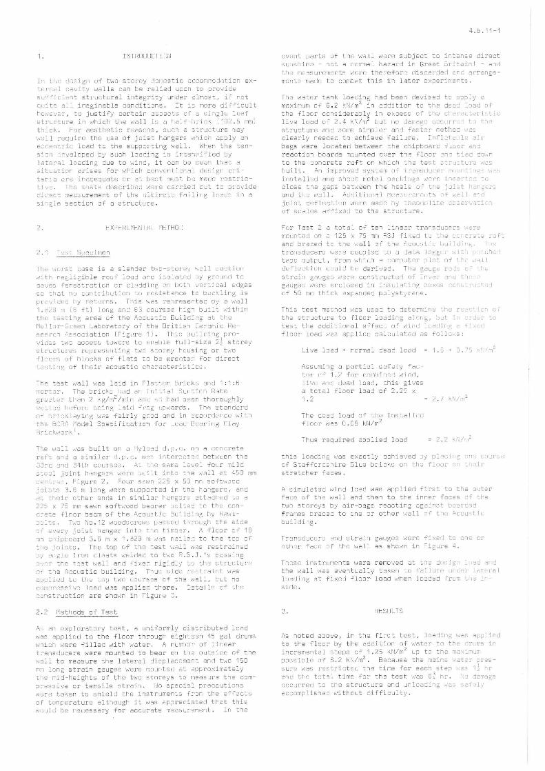
The worst case 15 a slender two-stor ey wa ll section with nei li gible roof load and isolated by grcund to eaves fenestrettcn or cl adding cn both va rtjcal e dges so that no contribut10n tu r s sistance to bu cklin g i s prc'lided by returns. Tl1is '"a,s rapre s e nted oy a wall 1 . b2S m i6 ft) lor-,g and 63 courS5S hign built within the test i ng area of the Acoustic B~ilding at t he Me llo r- Gr ee n Laboratory of tha British Ceramic Re ses r ch Ass ociation [Figl!ra 1) . ThlS building provid~s twc acaess towsrs to enable fwll-size 2l storey structu re s represenLing two storey housi~g or two fl ao rs of blocks of flats to be erectad for direct testi ng of their acoustic cheracteristics .
Th e test wall was laid in Flettcn Bricks and 1 : 1 : 6 morta r. Tha bricks had an Initial Su~tion Rate greater t han 2 kg/m2 /min and 50 had bssn thoroughly wet t ed before being laid frog upwards. Th8 stan cJ é'rd of brickleying wes fairl; gnod and in eccorcJonce with the BC RA Model Specification for Load-Beôring Clôy Bri ckwo rk 1 .
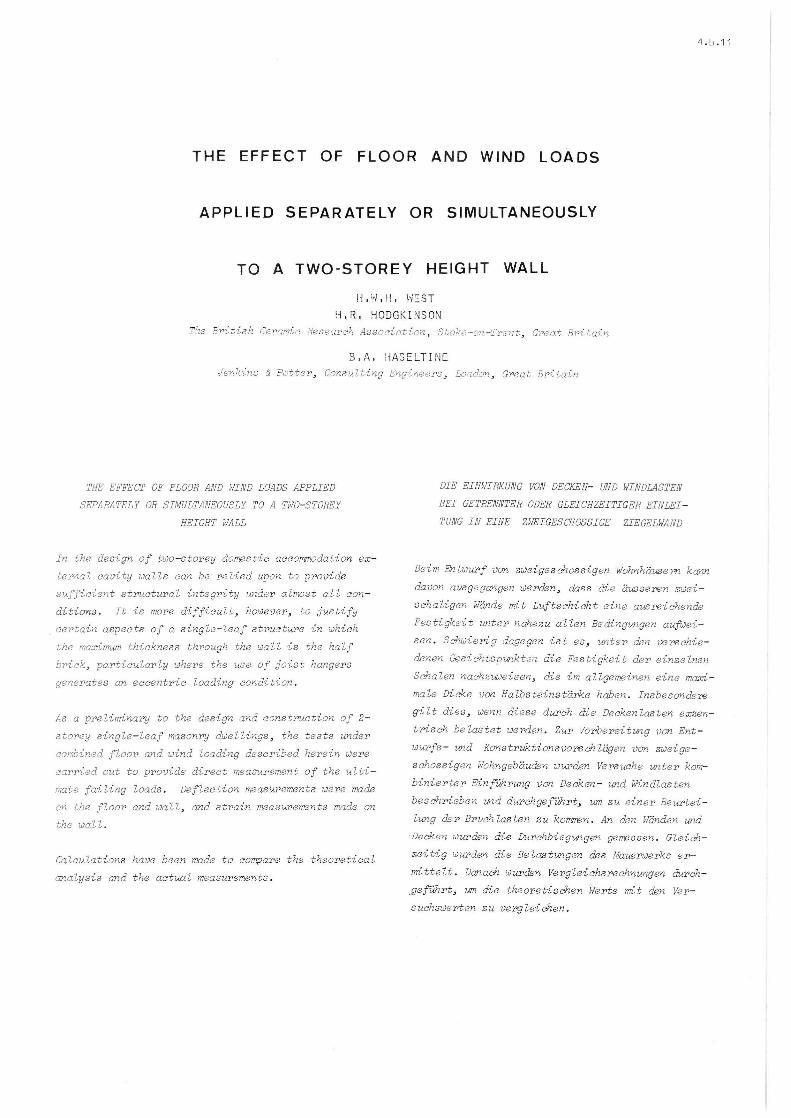
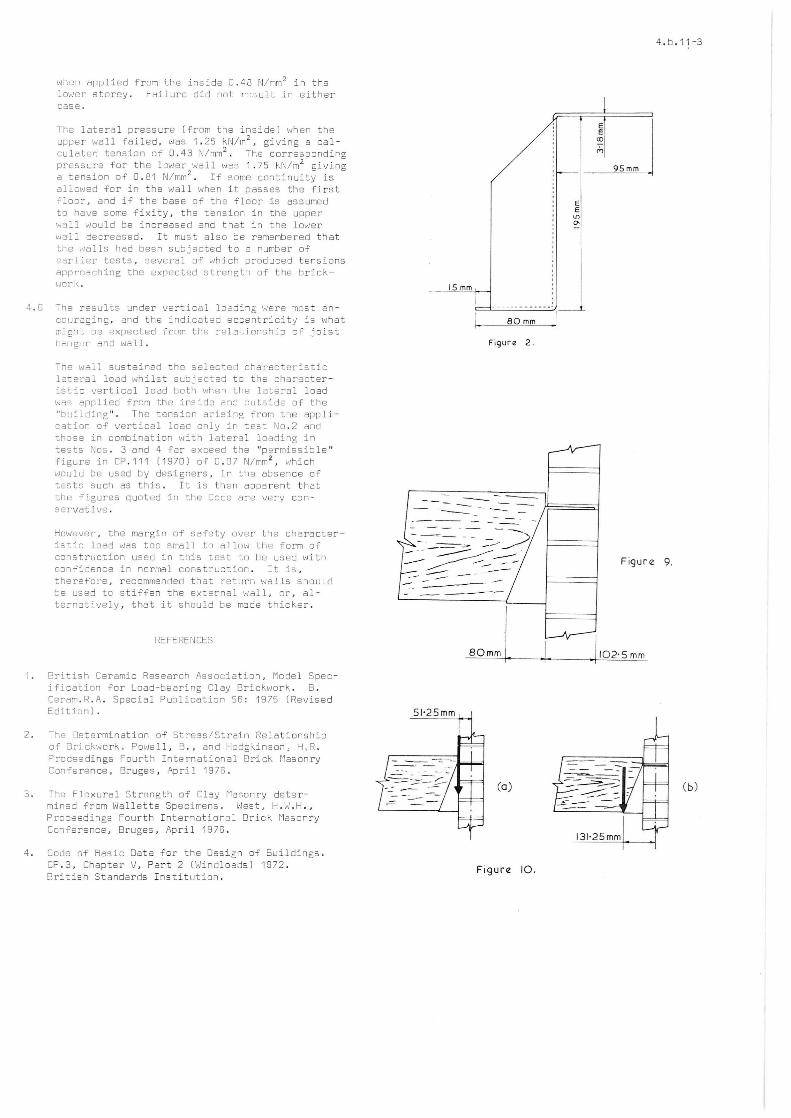
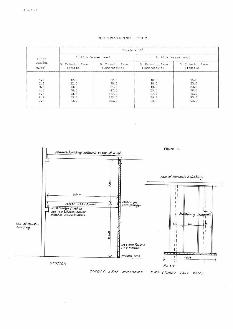
The wa l l was built on a Hyloed d . p . c . on a concrete r 6ft and a similar d . p . c . was interposed betw~en t he 33ro and 34th cOllrses . At the SArne leve I four mild s tea l joint hange !'s were built into the ',la11 at 45 0 mm centl'es , Figure 2 . FOLir SE1wn 22 5 x 50 n,m s oftwoo o joists 3.6 m l ong were suppcrted in th~ hangBrs. and at their other enrls in s i milar hangors ôtt a ch e d t o a 225 x 75 mrn sawn soí'ülOod bearer bolted to the concrete flGor be3rn cf the Asousti c Butlding by Ravilbel1:s . Two No . 12 woodscrews passed t hrough th e si de of eve r y j oist hanger into t hB timosr . A floor Df 18 mm ch i pboard 3 . 6 m x 1 . 829 m wô5 nai18d to tne top Df the jo i s ts. The top Df the test wall was restrainsd by angle iron cleats w81ded to t0iO R.S.J.· 2 pa3sing a ver the test wa l l and fixed rigidly to the structure of t he Acoustic building . Thus side rsstratnt wes applied to the top two courses of the well , but no cump ressive load was applied there. Oetails of the c onstruction are shO\,!n in Figure 3.
2.2 Methods of Test
As an exploratory test , a uniformly distributed load was applied t o the fI Dor through e ighteen 45 gal drums vJ hi crl were filled 'with vJater . A number of lInear transducers were mounted to bear on the outside of the wal l to measu re the lateral displacement and two 150 mm l ong strain gauges were mounted at approximately t:he mi d- heights of the two stcreys to rne as ur2 t he comprwss iv6 or tensile strain. No spacial precauti cns wore taken to shield the instrument s from the effe cts of temperature although it was appreciat e d that this vJOu l d be necessary for accurate measurement . In the
4.b .11-1
event parts Df the wall were subject to i nt en s e direct sunshine - not a normal hazard in Great 5 r ltain ! - and the measurements were therefore discarded ano ar r an ge ments made to cornbat this in later 8xperiments .
The water tank loading had been devis ed to epply a maximum of 6 . 2 kN/m2 in addition to the dead load Df the floor considerably in excess of th e characterlstic live load of 2 . 4 kN/m2 but no damag-e OCCLlr r e.l to the structure and sorne simpler and f asto r rr,e th od "Ias clearly needed to achieve fail ur e . InfletablB air bags were located between the chipb oard floor and reaction boards moun ted Qvsr the fI nar enc tied down to tne conc r ete raft on which lha test structura was built. An improved systern o í- t['üpsducer rrrun:ings l'J,"j5
installed ano sheBt nleti31 pacl , irr gs viBrE' inserted to close the gaps b et~8en the hGal s of trre joist hangsrs and tr.e wall. AdcJitional meaSLrtllTl8f1 t s of well erd joist deflection were madG by t heonn li te Cb3SrVi3tion of sCôIes affixed to the structure.
For Tsst 2 a total Df te n lir18ar t rans ducers w~ra mounted on a 125 x 75 mm RSJ fi xcid lu the ~cncr8t8 raft and braceo t c the wa ll Df the Acou s ti c buildir~. The tra ll sducers were coupled to a data 10ggEr '"it~ pl ~.Ch8d tapo output . from whi~h a computer p l ot Df lhe ~311 de f lection could be derived. Tha gauge ro~ of t~e straill gauges \tIferf-l con.stcuct 8r1 of In"",<;jr BrlG tl-,e '2 gauges ',v ere Enclosed in insulati ng boxes con' tru,-t Jd of 50 mm thick expõ:nded polysty r ane .
Thi s test melhod was used to Dete r mi ne the re3c+'on OT
the structure to floor loading a longo but i 1 crd8r to test the addit i onal effect o~ wi nd lcadipg a fi~Qd floor load was applied calcul ateo as follD~s:
Live load + normal dead load
Assuming a partial safety factor of 1 . 2 fnr combinad wind . live and dead load . this gives a total floo r load of 2 . 25 x 1 . 2 2.7 kN/m 2
The dead load of the installed floor was 0 .05 kN/m 2
Thus required applied load = 2 . 2 kN/r,,2
this loading was exact ly achieve d by placiag c~e course of Staffordshire Blue bricks on t he fIoor o~ 1:~eir
stretcher faces .
A simulated wind lo ad was applied f i rst to the oute r face of the wall and then to the in ne r f acas Df the t wo stcreys by air-bags reacting ag a i nst boardad f rames braced to one or other wall of t he Acoustic buil di r. g .
Tra ns ducers and strain gauges were fixEd to one or oth 8r f ace of the wall as shown in Fi gure 4 .
These instruments were remo 'led at t he d8sign load ard the wall was Bventual l y taken to faiIur e under loteral loading at fixeo floor load when loaded f l'U"1 Uld lr'
sids.
3 . RESIJLTS
As noted above. in the first test, loadi ng was appl i ad to the floor by the addition of water to the drums in incrementaI steps of 1 . 25 kN/m 2 up t o t he maximurn possible of 6.2 kN/ m2
• Because the ma ins wat2r pr3Ssure was restricted the time for e a ch step '33 11 hr an d t he total time for the test was 6~ hr . No demags occ urred to the structure and un l oading was safa!; acc omplished without difficulty.
4 . b . 11 -2
3.1 Variable floor l oading with no la~ e ral load
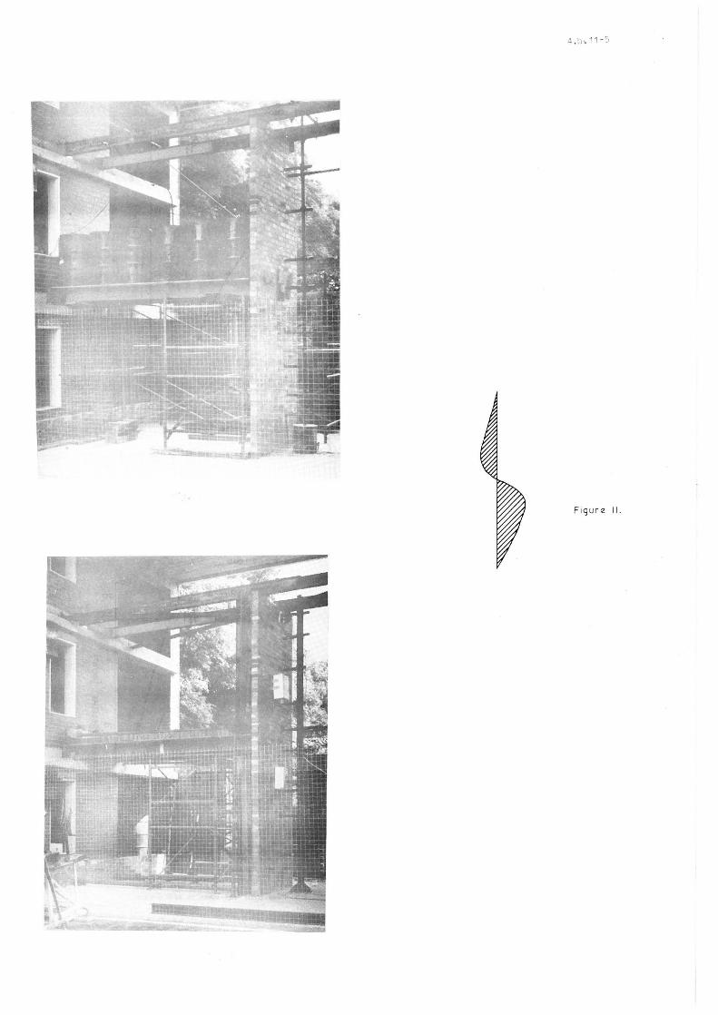
In th e sscond test the floor load ing wa3 appliod by air baga in increments af 1 kN/m 2 up to 12. 5 ~N/m2, when damage wa3 susLained . At this puint, the load on each joist hanger excesded 1 tonne and as a resu lt the tongues we r e plastically dsformeo and progressively bent, 50 that the horly Df tho hdngcr was pushed do ,~n the inner filco Df th2 wall ond tfle tonZlIc,; pulled out Df tI,e brlckdork . Tl1e joists ',Jere th,3n Suopol'ted on sCLlf fClld:Lng vJhi ch h ad be03n placed fLlr Ulat elJent uali ty . It was observecl t hat some Df the metal pac kings bctwe8n the hangers and the wdll had slipped Dut d u ring the fi nal s tag e Df th,] loading, as th e floor joists dcflected, 50 tl1ar wnan the hanger~ W8tB deforrr,ed there ,'Jas a g~p lletw 6cn th eHII arld tho brickwlr l<.. The br lcl<~worl(, slJsta :i. ned n0 tJürllsgu but ttl8 d e F18ction of lhe f Ioo r wô5 '11 . 4 I,',m at a flulI), ln acJ illg o f 7 . 7
kN/m 2 fj nd 1 7 . B Inm ar. a fl Dor loaclinti of 1[1, G f..ij/mm 2
The strain meAsuremBnt s are given in the TabJe .
3 . 2 Const ~n t flaor 10ôding and variable laterô l l oadil~ ---------.--------,--,--
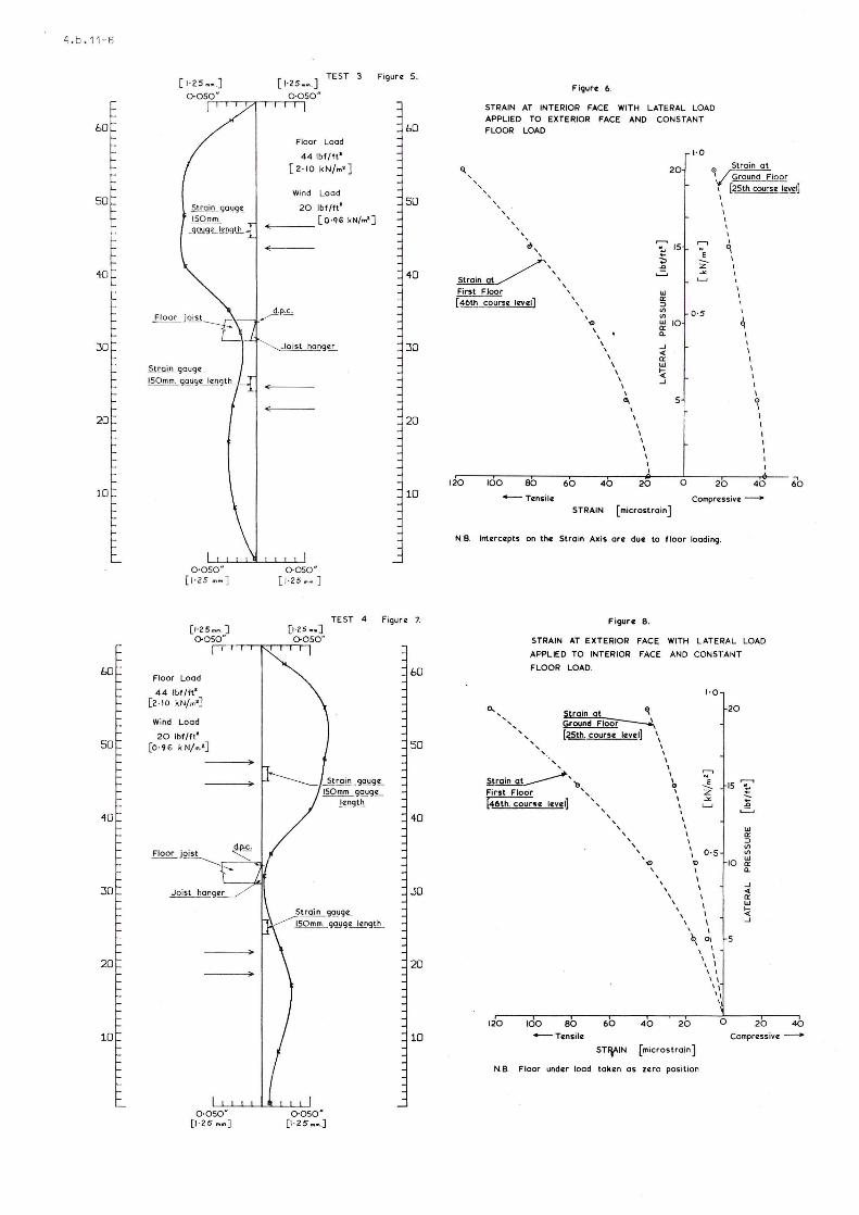
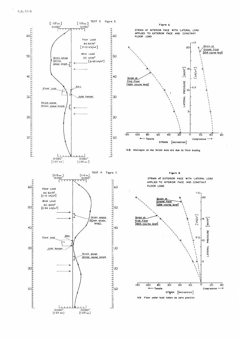
For the third test n ew joist hangors ware built into the wall us in g 1 : 3 cemsnt-fondu' sand mortal' . Ths joists were wedged at the and to improve thcir security over the condition Df th8 first two tost5 and to ensure that tho ha"gers '",ere in conlact vii t:l the walls. Th e floor load ~as fi~ed ot 2.2 ~N/m? and a prBssu re of 1 krJ/m2 \'''1~ ~PiJI i a d in ili 'T','rr,rClt3 rJf 0.25 kN/m 2 to the ouLside Df' th" Irlclll to silwlate \'Iind load.
The computer plot of the wall deflpction und8r tha cornbin Bd fI Dor ilnll hor.iz cm i Fll pr "c;Sur2 r'f ~. 2 ,'''Id 1 kfJ/m 2 respBctivelv i,r, given ill figllLl F . rh8 scrain measurem~nls are giv8n in Figure 6 . Tne fln~r cleflection remai.n ad :oo'-~stdnt duri.lg the laterdl IOdding . No damagB was 5 LJS téi ill'3d .
In the fourlh test the later31 loading WAS appliecl to the innar fac8 Df the w311 to simulate wind 5uct1on on the outsjde and th s tr~r'5dl_lcar~: BI-Id str'ain gau~es wer2 app lJ ed to the out'?r fuce. The lJr3ris ',JGre as for Test 3; th8 co:n;JLlLer pl:Jt of v/GIl defll?cLion unelSl ' th e cotr.billBd luar1s i5 gi'J8n in cif'un' 7 ar,e] t!18
strain measurem8nts in figura B. No d .. Jrnage was s ustainecJ.
As a final test the instrumentation "Jas remnveel , and with a floor load Df 2 . 2 kN/m 2
, the latpral prassure on the inside of lhe loJall vies incleased unU I the bricJ<.work 'fai la d . The top stor8y creckBd at a lateral pressure Df 1.25 krl l/l,12 iJetweell 1:h8 C,3rd and 54 crl courses. Th e pressure wad removed from the top slorsy a nel the pressure cn lhe lower storey incrs3sed . At a lateral press ure of 1. /5 kN/m 2 th e well crDckBd between th8 19th and 20trl cotJn-es.
4. IJISCUSSIDN
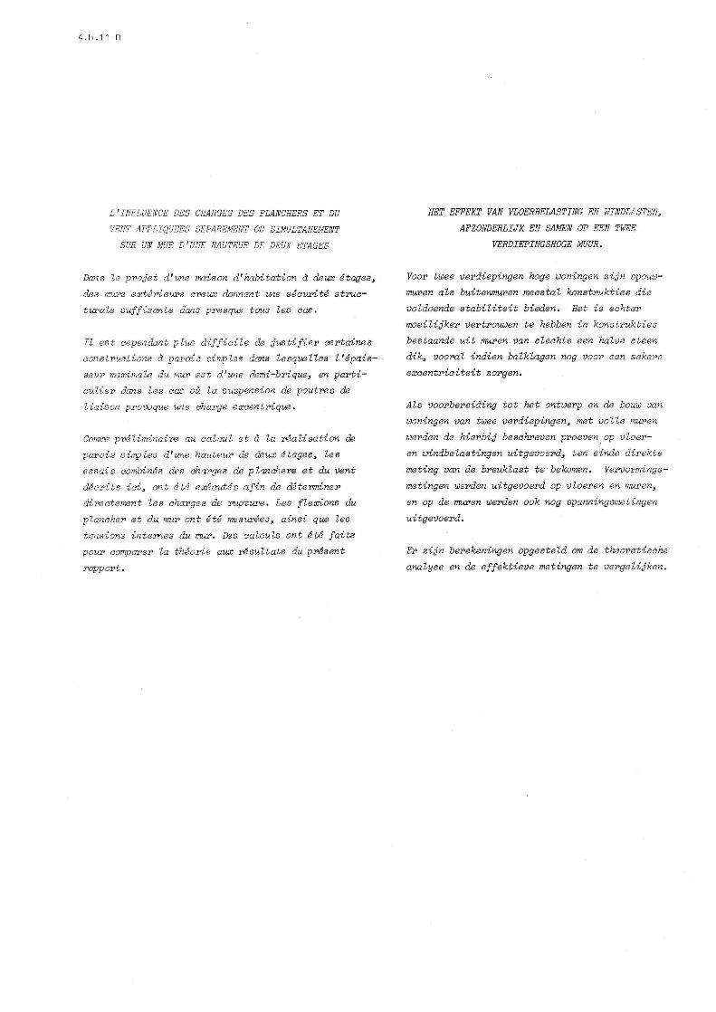
4.1 A joist ha nger is sP.t nn a wa ll as shown in Fi gure 9 . I n considering tl18 effect of a load applied throuBh A rigicJ joist carriecJ in the hanger, a decision must be taken on tha eccentricity of the load reI ative to lhe centre Df the wall. Wil l Lhe jaist be (a) so rig.d. and deflect 50 lit tle , that tha load is only applied as a shear at the face of the woll (Figure 1oa) o r (b) will def l ection Df the joist cause the load to dCt at the tip Df the harlfoer in a way ar""logous to structural steel design (Figure 100). In prActi ce it might ~e supposed that the true condi tio n woulrl lie between the two .
When considering case (aI in the liBht of the t est structure, lhe strlJss, irl the uppel' part Df the l ower wall , under chara~leristlc lOdds, but
with no roof load on t, unpsr part Df the wa ll anel assurning that UI8 n10íT10rlts Are e(lUdlly dis-tr j CJutferl ta th'l uJ1,J Pr cn 'I 10,",,[ ,'h,ll. "JOuld be +0.02 i!lrr.n2 (coro.p J "s -i 'i 0111. Th 8 corr"spondi.llg figure for case (',] ',IC'uld be -0.12 ~1/mr~2 rtens i,on) . A ~ind ll)ad would cause t~nsjon or conures3 j_on which would nesd to he ~rithn~ttcally Addp.d to the ilbnv8.
4 . 2 The maximum load sustairl "I by tl18 \".Jll at the time th2 joisL hln>,['[ f,I'], (1 in h!,·t 2 vJCJS 12 . 5 k~l/rr? , plus 0.5 k,'!I",2 sf'lf ,lei ',t of floo,- . If the H glJrps 'lunt~d ilc;~V'J f." GJ,;es (a) Bnd (b) are ITlodifierJ -FOI thL~-) JrJJ'i L.he ~trn~SGS h8come -0.013 I\I/,m? wld -0.']9 'I/'om' re'i lc:d 'VHl~J (bot h tenslotls) .
4 . 3 The assurrriÜdl \"':a" fTlar l , ir! t~,. (- c"trlJlat'ions trlê1t UiC~ Ir :CJVl.:llel i ,Jpnl i 'ri tn t 111) iA',ll J b~.' 'lhe jolsts wnuld DG sh JT f-- ~d. 1 I'J Y I .• ~ t..;Dfier and lG,,~8r '.!Jcl11. CPf ,!I~ ,r trl!"l ,JI I vJtl:c,h 1,he \r./al l is bui] t~ thp s1. i ,t fnl: S'i )r~ Ir th U;1("]rJ:--' Lll'd lO\..-Je r p':lrL arr (li likpl\ t t: f- :J3i'8 1 ;:Jnd~ll jt wnuld 08 Fair r to i,-j!<r l,,''-'i~ ;:1·rl:1 1 jnto t~8 low8 r woll. In th e> 'J~ I ,r 'jel ilt ~] [ Jldti:Jils ãn,s hels bp.8n t8h.8'l i il ti":J t ).1 N ,lI 311 1 ! ~ths LI, ti,+? lo'...:e r (FigllI'81'1). EC[iJ,ll\" UI')" i,' ':nr l:lkslly tél be a sudden cn,'3'l;,e of n:")lrr;rl1. ,::'t t!ll 1 /t:.1 ,Jf the joj5L nanQ'8r . ~\ 111 l~diIH~ ,r, y. 11 .""1; -j;~rfi~n ui the
Shô!-l2 Lll [-jB:IW~ 11, I" '~,, J f~ "r'r ! ll_. lF'crl =j::JSUiT,~~ d.
Tlw Ilklxir ,lJfl ~, '1" + ir 1 1J I I I 'n apD rO)(-ij;";,=:3tr:.ly ,-.Lilll ;r].:.. ]r- 1 t. 18 sLl'ôin m8 a'=' Uf ~rn('nL~j (r/5Lil CfJl!r'" 1. 1 j ~r:r il'2 str-:li ns Clt thc ~eak lCi::Hi 1 ,hit.: If:; j L' 1 I-- ~ F.::Ii ~8S ;JlJere r8:Jloved, i::h-;: L.:CL ntl1rj1j úF' Ifl I l,ll.ICldG
ac t j ng 1..3n t'H; f :Jljn I . I t I(]f" li I nII1 tl .,7 r-,:'J/mm 2
pl(IS 0.5 k'l/n,L s'cJ j .:' i "'l!, ~r~ d~n CiOt 'Jacy much for 10',lor loaos . fonsjd! r:"',, t, c' I 'ld drlsi ng from the solf '.'1°-1 , I":. cf t
";I::1'11 I ~ crJ Ict'ntr ic.~
the fI Jf"Jr l·:Jc.! '}:I: II J; 11 .,-, 1: ct PJTt frolTl lhe con'Ln? of the h1ell. i.tJ Iln~c·~t pX-Jrtly mi.dw=.!y b8tl:J28;l the extr,j,,!r:'H ."; in I l~',[ f 1'JcJ '::l~Hj lOb o The calcul at"ei r~aXimlJnl I "',c, l'ln 3t. 1.7 k !Im? i 5 n. 313 r~/rnrn2, \J'hich 18ad~ tC) ;:~II =- '. ~lll) +'~Jr t~2 brick-\JJork cf 435U '\!/;nt '),·!hj t, is j 111' C"1( r gl'fiBment
vJi.th tne quot,".J Vil] w'õ for th,.' S'll!" ('rick and 1: ~: 3 rnnrtêl' t ~~ 1: ,j tJ ) ,.l( '.' L li r: h Jd?.f.;j n30n 2 .
4 . 4 If the 8ccenlricitv cLllcllli~t2,-j ,']t,UI/.' 18 IIsed for the lllà1 of' 1'1 r':'J/;llL -3t ',.J 1; L il "Che Jn:i st h.:lngors fFli1 ed ~ the naxifTlum t.2i.f ~r.Jn \JJJS O. S:J ~J/lllm2 ~ a v8rl' hi gh fiI'UI'8. [v!éll If'tt ' n,s( 111 ',i 'F::lr the bl'j cf<. CJnr.:! r::llrt Ir r;r I!" ,1 .. t lL Lj r:j 111 thJ:> test gave an lJltLm~te fiE'XUl',cll stc8ngtl, uf 0.3 N/mrr,z . 3)
4 . 5 Bv compartson with the 10~d cf 11 kN/~2 , Lhe l oan used -ror the cOillbi.!l(Jd l'lL<:r"l ',r,ri ,,_~rtisEil 10ad
t R~, t" w ô " s m"l 1 - ? . í' f,; / 2 i r1' 1 ilfj i no, t h c 'ó 81 f '...;ej ght úf t.hl3 flp(!. TI), ] tL 1 AI 1(1 1J 1l~1f-:d W3S
1 kf'J/íG 2 ; tilis I:!as ôry'j_'Jed C~+· fr,]:ll [[1. J Urapter V ~ FiCrt:>, Win,:llrJ.-ds 19!~:. [,r,.j" ,p '],Icir Data for U-,o DsC' i p'n [J f F111i j i i r ,_1') I, J ~:- I 'I ,- l' ~ 1 fJO yc 3r
life f,~r thc hLlilclL"s 411,1 d II I"Ü wind spe8d Df 46 10/5. It \"'=iS 1 '?"11 'I lhê:t if Lhp loJorst ground rOt!gldlP 3S cat8?;IJry (1) '.'JFJ;·, U':-il:~(j d \/LJ l'y hi~i-' pr9s SUj'S ',",ould nõ!3ult (c[1;JrrJxirlat,,'ly 1. 5 l~r'~/rTi I and U'3t tlli ó 'ú'lu ld be Ulli'E~'Jirtir . I' -JiY, therefore~ u :!cir1ed to ij ,surnr L,iJ d '-,+_I Ur-r:IJf'b of the sürt hl:,jnrr t'lc.jteLJ 1 .... 'rulJ nrlf', L1[""l dllu',J,"")d to be
buil t i.n ail'y'tt- in[, "Ir rr f- ttiV" l)t ~l \' 3 rnughness i . 8 . outskirts Df citieR UI' small Lowns . By combinil1g the eff8cts Df a reasonable local suct ion and j.nter'nal Dr8~S rA, tllC fi~ul'e rF 1 kN/m2
was
selectBd when using 8 p~rtial safety factor Df 1.2.
When tho lateral l'lod W03 applien to the ou t si de Df the t8St strurtur", th~ ~~lrul 'dei tension lOélkinf' use :,r th,' "C, "I ri (:I I V 1 r,cJ 1 ,t"d by the 8i'lrli8c tasl: dno ,'SS()fTlill~ til' ,"",,118 to hr simpl y supported, was n. 47 fU nr,l· ·Ln t 'lP JI,por s Lor"y a nd
4 . 6
when applied from the inside 0.48 N/mm 2 in the lower storey . Failure did not result in either case .
The lateral pressure (from the inside1 when the upper wall failed , was 1 . 25 kN/m 2
, giving a calculaterl tension of 0 . 43 N/mm 2
• The cor r esponding pressure for the lower wall was 1 . 75 kN/m 2 giving a tension of 0 . 81 N/mm 2
• If some continuity is allowed for in the wall when it passes the fi r st f loor, and if the base of the floor is assumed to have some fix ity , the tension in the upper wall would be increased and that in the lower wall decreased . It must also be rememb ered that the walls had been subjected to a number of earli e r tests , sevEral Df whjch produced tensions approaching the expected strength Df the brick>'JO rk.
The results under vertical loading were most en couraging , and the indicated eccentricity is what might be expected from the relationship of joist hanger and wall.
The wall sustained the selected charscteristic lateral load whilst sub j ected to the character istic vertical load both when the lateral load was applied from the inside and outside Df the "building ". The tension arising from the application Df vertical load only in test No . 2 and those in combination \-/ith lateral loading in tests Nos . 3 and 4 far exceed the "permissible " figure in CP . 111 (19701 of 0 . 07 N/mm 2 , which would be used by designers, in the absence of tests such as this . It is then apparent that the figures quoted in the Code are very cons ervative .
However , the margin of safety over the characteristic load was toa small to allow the form of construction used in this test to be used with confidence in normal construc tion . It is , therefore , recommended that return walls shoul d be used to stiffen the externaI wall , ar , al ternatively , that it should be made thicker .
REFERENCES
1 . British Ceramic Research Association , Model Spec ification for Load-bearing Clay Brickwork . B. Cera~ . R . A . Special Publication 56: 1975 (Revised Edition1 .
2 . The Determination Df Stress/Strai n Relationship of 3rick"crk, PO\'Jel l, B., and Hodgkinson, H.R . Proceedi ngs Fourth International Brick Masonry Conference , B~uges, April 1976 .
3 . The Flexu r a l Strength of Clay Masonry determined from Wallette Specimens . West , H. W.H . , Proc8edings Fourth Internationa l Brick Masonry Conference , Bruges , April 1976 .
4 . Co de Df Basic Data for the Design of Buildings. CP . 3 . Chapter V, Part 2 (Windloads1 1972 . British Standards I nstitution .
15 mm
E E li) o-
, I -- --- - -- -- - .. ' -----L
~-----'8"-"'O-""-m m"-----ll Figure 2 ,
-- - ---~_. - -~ --=-~ ~-~ --- ---------------------------- ...........-- --- -- --:::::: - - ------ -
(o )
Fig ure 10.
4 . b . 11-3
I
Figur e 9.
( b )
4 . b . 11 - 4
STRAIN MEASUREME NTS - TEST 2
Strain x 10 6
Floo r At 25 t h Co urse Leve l At 46th Co urs e Leve l
Loadi ng on Ex te rior Face on I nt e rior Face On Exteri or Face On I nterio r Face kN/mm2 (Tens il e) (Compressive) ( Comp r ess i ve) (Te nsil e )
1 . 9 12 . 5 32.5 10 . 5 15 . O 2 . 9 22 . 0 49 . 0 16 .0 23 . 0 3. 8 30 . 5 65 . 5 19 . 5 30 . O 4 . 8 48 . 5 97.5 25. 0 38 . 0 5 . 7 59 . 5 137 . 0 27. 5 46 . 0 6 . 7 73 . 0 155 . 0 28 . 5 53 . 5 7 . 7 73 . 0 163 .5 28 . 5 53 . 5
I. c;f1Mmd1 J.-;,À''''1 ~ to _tpp qf Na.-U-11
Figure 3 .
rI ~
~ \\j
'I "
,/ 3 ·.b /ti . , r ,
1/ YLt7A /) OPc . U\ J!U~s 22S"J'SO/l1WV / [\
'I ' , ! ,
" II II / .JtJ7.th~u ;l-JOift.~!: ~xw to
US x:>o íof 000 tJea"er boiáQ te ~ b2atw.
' I ' I 'I I ,~,ee. ~3 ~
Ú!aLLo!~ ~w..g .
~ ~
....
I Of!:".,,,,, f, 1'1· 6;n~.
\V #n()~D LJ.I"C
SéC/T/ON . K
,I 4&rJ I, II 'I 'I 11 II I
fi I.
4SD Jlo 'I II
I' , I , I
" 1~29 .
" , I
TWO STOl?éY TéST W/fLt
4 . b . 11 - 5
Figure 11.
4 . b .1 1 - 6
bO
50
40
30
20
10
bO
50
40
30
20
10
Strain gQ!Jg~
150mm. 9~u9~9\h.. _.
0'050" [1·25 mm J
[1·25m. J 0050"
Floor Load
44 Ibl/ft' [ 2·10 kN/m'J
Wind Lood
20 Ibf/fI' [0·96 k N/.o·]
fi
0 ·050' [ 1·25 . m.]
TEST 3
Flaor Load
44lbf /ft'
[ 2' 10 kNfm' ]
Wind Load
20 Ibf / It'
_--- [0 '% kN/m' ]
~---
Joist hang~
0'050" [1·25 •• J
[125 •• J 0050"
TE ST 4
Figure 5.
bO
50
40
30
20
10
f igure 7.
bO
50
40
JO
5train 9qy9~ ~gQYg~g\h..
0·050' [1 · 2 5 ••. ]
20
10
Q. ,
Figur. 6.
STRAIN AT INTERIOR FACE WITH LATERAL LOAD APPLlED TO EXTERIOR FACE AND CONSTANT FLOOR LOAD
1· 0
20 o Strain a l
, , , , \/ Ground Flaor
I [25th. courso lev_O , , , , , , ,
~ , ,
~" " , First Flaor ,
[46~.0 1""01] \,
120 10 0 80 60
, '" , ,
\ , \
\
40
\ \ \ I ...
I
\ I I I \ I I I
20
~
;; .c
..=,
W o: :::> V) V)
w o: a.
...J « o: w !;( ...J
15 "e --Z
0 ·5 10
5
o
I
I q
q I I
\ \ I I
\
" \ \ \
20 40
Compr cz ssive ------STRAIN [micro'train]
N.S. Intczrcczpts on the Stroin Axis are due to f loor loading.
Fi9ur. 8 .
STRAIN AT EXTERIOR FACE WITH LATERAL LOAD
APPLlED TO INTERIOR FACE AND CON5TAN T
FLOOR LOAD.
, ,
~\rgin gt <li Ground FI~ [~ cours. lovol] '.
I I I I I
~'" lo Fir,t Flcor " [46th. COUr1 1l leveI] ",
, , , ,
I I I \
I
1·0
I I I
, , , I 0·5
120 100 80 60
, .., ,
40
, , , \
\
, , ,
20
I ., I I I I
I I \
b <li I I
I I
'. \ I I I I 'I
" I
20
15 T .c --=-w o: :::> V) V)
10 w o: a.
...J « o: w !;( ...J
5
O 20 4Q
~Tclnsi le Compress ive ----+
5T~IN [micros troin ]
N.B. Flcor under load tokczn a s le ro position

4 . b . 11 - 5
Figure 11.
4 . b .1 1-6
bO
50
40
30
5tra in_ gQ1lg~
ISO'"!"c.. 99..u9~9\.!!... _
20
10
0 ' 0 50" [ 1·25 MM ]
bO Floor Lood
44 lol/n ' [ 2· 10 kN/m'J
Wind Load
50 20 Ibf/tt'
[0' 9 6 k N/ .. 2.] :>
40
30
:>
20 :>
10
0 ·050' [1 ' 25 m ... )
TEsT 3
Flcor Load
44lbf / ft'
[ 2 '10 kN/m2.]
Wind Load
20 Ibf/ft'
~~ ___ [O ·qG kN/m']
~---
Joist han9~
0 '0 50" [1 ·25 •• . ]
Figuro 5.
bO
50
40
30
20
10
TEST 4 FigurlZ 7. [1 ·25 • • J 0050 "
bO
50
~ 2!IQUL9QY.9~ IsOmm ggyg!L
~g!.h.
40
030
Strain 9QY9~ ~ggyg~g\.!!...
20
10
0 '050' [ 1· 25 •• ]
Figuro 6.
STRAIN AT INTERIOR FACE WITH LATERAL LOAO APPLlEO TO EXTERIOR FACE ANO CONSTANT FLOOR LOAO
, , , , , , , , , , , , ~',
~"" , First Floor ,
(46~ •• IOV.I) "
120 100 80 60
, .., \ ,
\ , \
\
40
, , 0
20
15 N
e S --:2 z -"
lU Ir ~ U'J 0 ' 5 U'J lU 10 Ir Q.
...J <: Ir lU
\ ~ \ ...J \ \ ... 5
I
\ \ \ I \ \
20 O
I
"', , I I I
g I , \
, \
'" \ \ \
20 40
-------- Tensilc Comprczssivcz ---. STRAIN [microstrainJ
N.S. Interc.pts on th. Stroin Axis ore due to floor loading.
Figur. 8.
STRAIN AT EXTERIOR FACE WITH LATERAL LOAO
APPLlEO TO INTERIOR FACE ANO CONSTANT
FLOOR LOAO
1'0
<lo. ~lcgin gl ~ 20 , , , , Ground FI~ , [25th. cours. l.v.I) \ , , \ , I , I , I , \
~~'" I
,., \
N
e 15 ..--. .. Z- ~ First Flcor " I
[46th. cou ... lovoi) , \ .;< ,
\ '-' .Q , I ..::.. , \ , , I lU , \ Ir , , ~ ,
I U'J , 0 ' 5 U'J , I lU -o ., 10 Ir , \ Q. , , ,
\ ...J , <: , I Ir \ , lU , , ~ \
\ \ ...J
\ b 0\
\ , \ , \ I \ \ I \ I I, I,
I
120 100 80 60 40 20 O 20
60
40
+--- Tcznsilcz Compressivc ---
STflAlN [microstroin]
N.S. Flcor under lood token as z!ZrQ position


![JHEP04(2015)106 - CORE · Wino ≡(M χ) = 2.7-2.9TeV [8–10]. In principle, we may further constrain the wino (DM) via direct detection. However, the cross section for a TeV wino](https://img.pdfslide.net/doc/110x75/5fefc8eb6d44440b767234c5/jhep042015106-core-wino-am-27-29tev-8a10-in-principle-we-may.jpg)