Embed Size (px)
Citation preview

The Effect of Foot Compliance Encoded in the Windlass Mechanism onthe Energetics of Human Walking
Seungmoon Song1, Christopher LaMontagna2, Steven H. Collins2, and Hartmut Geyer1
Abstract— The human foot, which is the part of the bodythat interacts with the environment during locomotion, consistsof rich biomechanical design. One of the unique designs ofhuman feet is the windlass mechanism. In a previous simulationstudy, we found that the windlass mechanism seems to improvethe energy efficiency of walking. To better understand theorigin of this efficiency, we here conduct both simulation andexperimental studies exploring the influence of foot compliance,which is one of the functionalities that the windlass mechanismembeds, on the energetics of walking. The studies show thatwalking with compliant feet incurs more energetic costs thanwalking with stiff feet. The preliminary results suggest that theenergy saved by introducing the windlass mechanism does notoriginate from the compliance it embeds. We speculate that theenergy savings of the windlass mechanism are related more toits contribution to reducing the effective foot length in swingthan to providing compliance in stance.
I. INTRODUCTION
Ideally, prosthetic legs should restore or surpass thefunctionality of that of intact human limbs, substantiallyimproving the quality of life for amputees. Many groupsin industry and academia are investing in related researchto achieve this goal [1]–[6]. However, few of the studiesinvestigate the potential benefits of the rich biomechanicaldesign of human feet [7], [8], the body part that mostlyinteracts with the environment during locomotion.
One of the unique features of human feet is the windlassmechanism. The windlass mechanism engages the longitu-dinal foot arch and the toe segment by the plantar fascia(Fig. 1-a), a thick tendon that spans from the underside ofthe heel to the toe [9], [10]. Previous biomechanical studieson the windlass mechanism focus on its functionality ofpassively articulating the toe segment [11]–[13]. Anotherfunctionality of the windlass mechanism is to modulate thestiffness of the foot depending on the load the foot is bearing.While the foot segment is flexible at normal configuration(marked in gray in Fig. 1-b), the foot stiffens as it bearsweight and the plantar fascia gets loaded (marked in blackin Fig. 1-b).
In a previous simulation study [14], we investigated thewindlass mechanism’s potential of improving the energyefficiency of walking. We showed that walking with feet thatincorporate the windlass mechanism could save more than15% of the energetic cost as compared to walking without the
1S. Song and H. Geyer are with the Robotics Institute, CarnegieMellon University, 5000 Forbes Avenue, Pittsburgh, PA 15213, USA.{smsong,hgeyer} at cs.cmu.edu
2C. LaMontagna and S.H. Collins are with the Department of MechanicalEngineering, Carnegie Mellon University, 5000 Forbes Avenue, Pittsburgh,PA 15213, USA. {cjlamont,stevecollins} at cmu.edu
mechanism. We hypothesized that the energy saving comeseither from the foot compliance introduced by the windlassmechanism or from its property of reducing the effective footlength in swing.
In this paper, we investigate the first option: Do compliantfeet improve the energy efficiency of walking? To addressthis question, we develop a foot model, which allows to varycompliance independent of foot length, and test the influenceof foot compliance on energy efficiency through simulationand experimental studies (section II and III, respectively).Our preliminary results show that compliant feet actuallyworsen the energy efficiency of walking (section IV). Thissuggests that the energy saving of the windlass mechanismoriginates rather from the foot length changing betweenstance and swing (section V).
II. SIMULATION EXPERIMENT OF HUMANWALKING WITH COMPLIANT FEET
A. Neuromuscular Human Walking Model
We used a forward dynamic simulation model of thehuman musculoskeletal system and its neural control [14],[15] (Fig. 2). The model generates steady walking behaviorwith human-like kinematics, kinetics, and muscle activations.The musculoskeletal model is planar and consists of thetrunk, thighs, shanks and feet segments, which are connectedby hip, knee and ankle revolute joints. The joints are actuatedby seven Hill-type muscle models per leg, five of which aremonoarticular muscles (soleus, SOL; tibialis anterior, TA;vastii group, VAS; gluteus maximus, GLU; and groupedhip flexors, HFL) and two of which are biarticular ones(gastrocnemius, GAS and hamstring group, HAM). Thecontractile elements of the muscle models take stimulationsignals between 0 and 1, and each muscle force produces
heel ball toe
MTJ
MTPJ
PF
(a) (b)
Fig. 1. The windlass mechanism of human feet. (a) Key components of thewindlass mechanism: the plantar fascia (PF), which wraps around the balland connects the heel to the toe; the midtarsal joint (MTJ); the metatarsalphalangeal joint (MTPJ); and the toe segment. When the foot is loaded (redarrows), the windlass mechanism keeps the foot arch from collapsing bypulling the heel toward the ball as shown in (b).
35th Annual International Conference of the IEEE EMBSOsaka, Japan, 3 - 7 July, 2013
978-1-4577-0216-7/13/$26.00 ©2013 IEEE 3179
F-
F+
F+L+
F+
L+
F+L+L-
F+
kMTJ
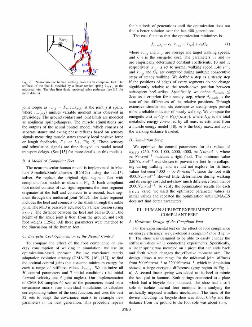
Fig. 2. Neuromuscular human walking model with compliant feet. Thestiffness of the foot is modeled by a linear torsion spring kMTJ at themidtarsal joint. The blue lines depict modeled reflex pathways (see [15] formore details).
joint torque as τm,j = Fm rm(ϕj) at the joint j it spans,where rm(ϕj) mimics variable moment arms observed inphysiology. The ground contact and joint limits are modeledas nonlinear spring-dampers. The muscle stimulations arethe outputs of the neural control model, which consists ofseparate stance and swing phase reflexes based on sensorysignals measuring muscle states (mostly local positive forceor length feedbacks, F+ or L+, Fig. 2). These sensoryand stimulation signals are time-delayed, to model neuraltransport delays. (See [15] for more details on this model.)
B. A Model of Compliant Feet
The neuromuscular human model is implemented in Mat-Lab Simulink/SimMechanics (R2012a) using the ode15ssolver. We replace the original rigid segment feet withcompliant foot models as shown in Fig. 2. Each compliantfoot model consists of two rigid segments; the front segmentoriginates at the ball and connects to a second, back seg-ment through the midtarsal joint (MTJ). The latter segmentincludes the heel and connects to the shank through the anklejoint. The MTJ is passively actuated by a linear torsion springkMTJ . The distance between the heel and ball is 20cm, theheight of the ankle joint is 8cm from the ground, and eachfoot weighs 1.25kg. All these parameters were matched tothe dimensions of the human foot.
C. Energetic Cost Optimization of the Neural Control
To compare the effect of the foot compliance on en-ergy consumption of walking in simulation, we use anoptimization-based approach. We use covariance matrixadaptation evolution strategy (CMA-ES, [16], [17]), to findthe optimal control gains that consume minimum energy foreach a range of stiffness values kMTJ . We optimize all30 control parameters and 7 initial conditions (the initialforward velocity and 6 joint angles). Our implementationof CMA-ES samples 64 sets of the parameters based on acovariance matrix, runs individual simulations to calculatecorresponding values of the cost function, and uses the best32 sets to adapt the covariance matrix to resample newparameters in the next generation. This procedure repeats
for hundreds of generations until the optimization does notfind a better solution over the last 400 generations.
The cost function that the optimization minimizes is
Jsteady = c1 |xavg − xtgt|+ c2CE (1)
where xavg and xtgt are average and target walking speeds,and CE is the energetic cost. The parameters c1 and c2are empirically determined constant coefficients, 10 and 1,respectively. xtgt is set to normal walking speed 1.4ms−1,and xavg and CE are computed during multiple consecutivesteps of steady walking. We define a step as a steady stepif the positions of edges of every segments do not changesignificantly relative to the touch-down position betweensubsequent heel-strikes. Specifically, we define dsteady ≤3cm as a criterion for a steady step, where dsteady is thesum of the differences of the relative positions. Throughextensive simulations, six consecutive steady steps provedto be a reliable indicator of steady walking. We compute theenergetic cost as CE = EM/(mxd), where EM is the totalmetabolic energy consumed by all muscles estimated froma muscle energy model [18], m is the body mass, and xd isthe walking distance traveled.
D. Simulation Setup
We optimize the control parameters for six values ofkMTJ (250, 500, 1000, 2000, 4000, ∞ Nmrad−1, where∞ Nmrad−1 indicates a rigid foot). The minimum value250Nmrad−1 was chosen to prevent the foot from collaps-ing during walking, and we did not explore for stiffnessvalues between 4000 ∼ ∞ Nmrad−1, since the foot with4000Nmrad−1 showed little deformation during walkingand its energy cost did not show much difference from that of2000Nmrad−1. To verify the optimization results for eachkMTJ value, we used the optimized parameter values asinitial values and repeated the optimization until CMA-ESdoes not find better parameters.
III. HUMAN SUBJECT EXPERIMENT WITHCOMPLIANT FEET
A. Hardware Design of the Compliant Foot
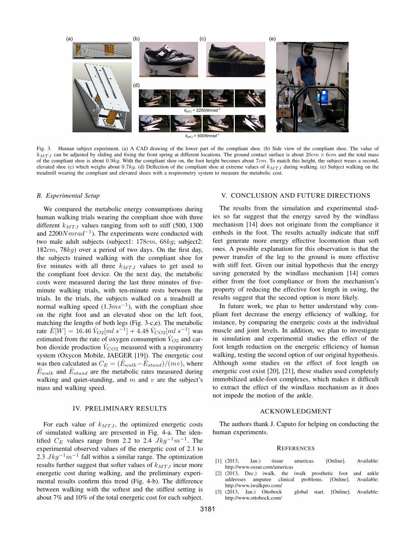
For the experimental test on the effect of foot complianceon energy efficiency, we developed a compliant shoe (Fig. 3-b). The shoe was designed to be able to easily change thestiffness values while conducting experiments. Specifically,a linear spring was mounted on a piece that can slide backand forth which changes the effective moment arm. Thedesign allows a test range for the midtarsal joint stiffnessfrom 500Nmrad−1 to 2200Nmrad−1, which in simulationshowed a large energetic difference (gray region in Fig. 4-a). A second linear spring was added at the heel to mimicthe heel pad in humans. Both springs connected to a platewhich had a bicycle shoe mounted. The shoe had a stiffsole to isolate internal foot motions from studying theartificially imposed windlass mechanism. The mass of thedevice including the bicycle shoe was about 0.9kg and thedistance from the ground to the foot sole was about 7cm.
3180
(b) (c)
(d)
(e)
kMTJ = 2200Nmrad-1
kMTJ = 500Nmrad-1
(a)
Fig. 3. Human subject experiment. (a) A CAD drawing of the lower part of the compliant shoe. (b) Side view of the compliant shoe. The value ofkMTJ can be adjusted by sliding and fixing the front spring at different locations. The ground contact surface is about 20cm× 6cm and the total massof the compliant shoe is about 0.9kg. With the compliant shoe on, the foot height becomes about 7cm. To match this height, the subject wears a second,elevated shoe (c) which weighs about 0.7kg. (d) Deflection of the compliant shoe at extreme values of kMTJ during walking. (e) Subject walking on thetreadmill wearing the compliant and elevated shoes with a respirometry system to measure the metabolic cost.
B. Experimental Setup
We compared the metabolic energy consumptions duringhuman walking trials wearing the compliant shoe with threedifferent kMTJ values ranging from soft to stiff (500, 1300and 2200Nmrad−1). The experiments were conducted withtwo male adult subjects (subject1: 178cm, 68kg; subject2:182cm, 78kg) over a period of two days. On the first day,the subjects trained walking with the compliant shoe forfive minutes with all three kMTJ values to get used tothe compliant foot device. On the next day, the metaboliccosts were measured during the last three minutes of five-minute walking trials, with ten-minute rests between thetrials. In the trials, the subjects walked on a treadmill atnormal walking speed (1.3ms−1), with the compliant shoeon the right foot and an elevated shoe on the left foot,matching the lengths of both legs (Fig. 3-c,e). The metabolicrate E[W ] = 16.46 VO2[ml s
−1] + 4.48 VCO2[ml s−1] was
estimated from the rate of oxygen consumption VO2 and car-bon dioxide production VCO2 measured with a respirometrysystem (Oxycon Mobile, JAEGER [19]). The energetic costwas then calculated as CE = (Ewalk−Estand)/(mv), whereEwalk and Estand are the metabolic rates measured duringwalking and quiet-standing, and m and v are the subject’smass and walking speed.
IV. PRELIMINARY RESULTS
For each value of kMTJ , the optimized energetic costsof simulated walking are presented in Fig. 4-a. The iden-tified CE values range from 2.2 to 2.4 Jkg−1m−1. Theexperimental observed values of the energetic cost of 2.1 to2.3 Jkg−1m−1 fall within a similar range. The optimizationresults further suggest that softer values of kMTJ incur moreenergetic cost during walking, and the preliminary experi-mental results confirm this trend (Fig. 4-b). The differencebetween walking with the softest and the stiffest setting isabout 7% and 10% of the total energetic cost for each subject.
V. CONCLUSION AND FUTURE DIRECTIONS
The results from the simulation and experimental stud-ies so far suggest that the energy saved by the windlassmechanism [14] does not originate from the compliance itembeds in the foot. The results actually indicate that stifffeet generate more energy effective locomotion than softones. A possible explanation for this observation is that thepower transfer of the leg to the ground is more effectivewith stiff feet. Given our initial hypothesis that the energysaving generated by the windlass mechanism [14] comeseither from the foot compliance or from the mechanism’sproperty of reducing the effective foot length in swing, theresults suggest that the second option is more likely.
In future work, we plan to better understand why com-pliant feet decrease the energy efficiency of walking, forinstance, by comparing the energetic costs at the individualmuscle and joint levels. In addition, we plan to investigatein simulation and experimental studies the effect of thefoot length reduction on the energetic efficiency of humanwalking, testing the second option of our original hypothesis.Although some studies on the effect of foot length onenergetic cost exist [20], [21], these studies used completelyimmobilized ankle-foot complexes, which makes it difficultto extract the effect of the windlass mechanism as it doesnot impede the motion of the ankle.
ACKNOWLEDGMENT
The authors thank J. Caputo for helping on conducting thehuman experiments.
REFERENCES
[1] (2013, Jan.) ossur americas. [Online]. Available:http://www.ossur.com/americas
[2] (2013, Dec.) iwalk. the iwalk prosthetic foot and ankleaddresses amputee clinical problems. [Online]. Available:http://www.iwalkpro.com/
[3] (2013, Jan.) Ottobock global start. [Online]. Available:http://www.ottobock.com/
3181

kMTJ (Nm rad-1)0 42 31 Inf
CE (
J kg
-1 m
-1)
2.2
2.3
2.4
x 103 kMTJ (Nm rad-1) x 1030.5 1.3 2.2
CE (
J kg
-1 m
-1)
2.0
2.4
kMTJ (Nm rad-1) x 1030.5 1.3 2.2
(a) Simulation (b) ExperimentSubject 1 Subject 2
2.2
CE (
J kg
-1 m
-1)
2.0
2.4
2.2
Fig. 4. Results of the simulation and experimental studies. (a) Minimized energetic costs for each value of kMTJ . The shaded area indicates the rangeof kMTJ that the hardware compliant shoe covers, and the dotted lines correspond to the kMTJ values used in the human subjects experiments. (b)Preliminary results for two subjects.
[4] M. Eilenberg, H. Geyer, and H. Herr, “Control of a powered ankle-foot prosthesis based on a neuromuscular model,” IEEE Trans NeuralSyst Rehabil Eng, vol. 18, no. 2, pp. 164–173, 2010.
[5] S. Collins and A. Kuo, “Recycling energy to restore impaired anklefunction during human walking,” PloS one, vol. 5, no. 2, p. e9307,2010.
[6] F. Sup, H. Varol, and M. Goldfard, “Upslope walking with a poweredknee and ankle prosthesis: Intitial results with an amputee subject,”IEEE/ASME Trans. Neural. Syst. Rehabil. Eng., vol. 19, no. 1, pp.71–78, 2011.
[7] J. H. Hicks, “The mechanics of the foot - i. the joints,” J. Anat., vol. 87,no. 4, pp. 345–357, 1954.
[8] S. Scott, D. Winter, et al., “Biomechanical model of the human foot:kinematics and kinetics during the stance phase of walking.” Journalof biomechanics, vol. 26, no. 9, p. 1091, 1993.
[9] F. Bojsen-Moller and K. E. Flagstad, “Plantar aponeurosis and internalarchitecture of the ball of the foot,” J. Anat., vol. 121, no. 3, pp. 599–611, 1976.
[10] P. J. Briggs and P. A. Tansey, “Active and passive mechanisms in thecontrol of supination,” Foot Ankle Surg., vol. 7, pp. 131–136, 2001.
[11] J. H. Hicks, “The mechanics of the foot - ii. the plantar aponeurosisand the arch,” J. Anat., vol. 88, no. 1, pp. 25–30, 1954.
[12] A. Kappel-Bargas, R. Woolf, M. Cornwall, and T. Mcpoil, “The wind-lass mechanism during normal walking and passive first metatarsal-phalangeal joint extension,” Clinical Biomechanics, vol. 13, no. 3, pp.190–194, 1998.
[13] E. Fuller, “The windlass mechanism of the foot - a mechanical modelto explain pathology,” Journal of the American Podiatric MedicalAssociation, vol. 90, no. 1, pp. 35–46, 2000.
[14] S. Song and H. Geyer, “The energetic cost of adaptive feet in walking,”in Robotics and Biomimetics (ROBIO), 2011 IEEE InternationalConference on. IEEE, 2011, pp. 1597–1602.
[15] H. Geyer and H. M. Herr, “A muscle-reflex model that encodesprinciples of legged mechanics produces human walking dynamicsand muscle activities,” IEEE Trans. Neural Syst. Rehab. Eng., vol. 18,no. 3, 2010.
[16] N. Hansen, “The cma evolution strategy: A comparing review,” To-wards a New Evolutionary Computation. Advances on Estimation ofDistribution Algorithms. Springer, p. 75.102, 2006.
[17] S. Song and H. Geyer, “Regulating speed and generating large speedtransitions in a neuromuscular human walking model,” in Robotics andAutomation (ICRA), 2012 IEEE International Conference on. IEEE,2012, pp. 511–516.
[18] B. R. Umberger, K. G. Gerritsen, and P. E. Martin, “A model of humanmuscle energy expenditure,” Comp. Meth. Biomech. Biomedic. Eng.,vol. 6, no. 2, pp. 99–111, 2003.
[19] (2013, Jan.) Carefusion, oxycon moblie - carefusion. [Online].Available: http://www.carefusion.com.au
[20] P. Adamczyk, S. Collins, and A. Kuo, “The advantages of a rollingfoot in human walking,” Journal of Experimental Biology, vol. 209,no. 20, pp. 3953–3963, 2006.
[21] T.-w. Huang, K. E. Zelik, P. G. Adamczyk, and A. D. Kuo, “Effect offoot length on walking with a compliant foot,” in Gait and ClinicalMovement Analysis Society, 2012.
3182