Embed Size (px)
Citation preview

HAL Id: hal-00498972https://hal.archives-ouvertes.fr/hal-00498972
Submitted on 9 Jul 2010
HAL is a multi-disciplinary open accessarchive for the deposit and dissemination of sci-entific research documents, whether they are pub-lished or not. The documents may come fromteaching and research institutions in France orabroad, or from public or private research centers.
L’archive ouverte pluridisciplinaire HAL, estdestinée au dépôt et à la diffusion de documentsscientifiques de niveau recherche, publiés ou non,émanant des établissements d’enseignement et derecherche français ou étrangers, des laboratoirespublics ou privés.
The effect of heat transfer on the pressure drop througha heat exchanger for aero engine applications
C. Albanakis, K. Yakinthos, K. Kritikos, D. Missirlis, A. Goulas, P. Storm
To cite this version:C. Albanakis, K. Yakinthos, K. Kritikos, D. Missirlis, A. Goulas, et al.. The effect of heat transfer onthe pressure drop through a heat exchanger for aero engine applications. Applied Thermal Engineering,Elsevier, 2008, 29 (4), pp.634. �10.1016/j.applthermaleng.2008.03.034�. �hal-00498972�

Accepted Manuscript
The effect of heat transfer on the pressure drop through a heat exchanger for
aero engine applications
C. Albanakis, K. Yakinthos, K. Kritikos, D. Missirlis, A. Goulas, P. Storm
PII: S1359-4311(08)00166-X
DOI: 10.1016/j.applthermaleng.2008.03.034
Reference: ATE 2460
To appear in: Applied Thermal Engineering
Received Date: 12 December 2007
Revised Date: 29 February 2008
Accepted Date: 14 March 2008
Please cite this article as: C. Albanakis, K. Yakinthos, K. Kritikos, D. Missirlis, A. Goulas, P. Storm, The effect of
heat transfer on the pressure drop through a heat exchanger for aero engine applications, Applied Thermal
Engineering (2008), doi: 10.1016/j.applthermaleng.2008.03.034
This is a PDF file of an unedited manuscript that has been accepted for publication. As a service to our customers
we are providing this early version of the manuscript. The manuscript will undergo copyediting, typesetting, and
review of the resulting proof before it is published in its final form. Please note that during the production process
errors may be discovered which could affect the content, and all legal disclaimers that apply to the journal pertain.

ACCEPTED MANUSCRIPT
1
The effect of heat transfer on the pressure drop through a heat exchanger
for aero engine applications
C. Albanakis, K. Yakinthos*, K. Kritikos, D. Missirlis, A. Goulas
Laboratory of Fluid Mechanics & Turbomachinery
Department of Mechanical Engineering
Aristotle University of Thessaloniki, Greece
and
P. Storm
MTU Aero Engines GmbH
Dachauerstrasse 665
80995 München, Germany
Abstract
This work is focused on the experimental study of the performance of a heat exchanger
designed for aero engine applications. The heat exchanger is operating as a heat
recuperator by taking advantage of the thermal energy of the exhaust gas of the aero
engine in order to obtain a better combustion with less pollutant emissions. The
experimental study has been performed in a wind-tunnel by taking detailed flow and
* Corresponding author E-mail: [email protected]

ACCEPTED MANUSCRIPT
2
thermal measurements on a 1:1 model of the heat exchanger under various operating
conditions described by the hot-gas inlet mass flow-rates and its spatial direction
(different angles of attack and inclination) towards the heat exchanger. The hot-gas has
been modeled with preheated air. Six sets of measurements have been carried-out for
different hot-gas inlet and outlet temperatures, including also isothermal measurements
without any heat transfer in order to have a reference point for the pressure drop of the
flow through the device. The experimental results showed that the effect of the angle of
attack on the pressure drop is significant whilst the effect of the angle of inclination is
negligible. Additionally, the pressure drop through the heat exchanger is greatly
affected by the heat transfer.
Keywords: Heat exchanger; Pressure drop; Heat transfer; Aero engine
1. Introduction
Tubes bundle heat exchangers are widely used as coolers, heaters, evaporators,
condensers, recuperators in the aerospace and power industry. The design of a heat
exchanger of this type is a complex task, since many factors have to be considered, such
as the thermal efficiency, the pressure drop which is imposed to the flow field and
others. In the past, a lot of work has been carried-out regarding, also, the flow
development through heat exchangers mainly focused on the effects of the tube shape to
the flow development. For example, Boetler et al. [1], Brauer [2], Schulenberg [3],
Bordalo and Saboya [4], Saboya and Saboya [5] and Rocha et al. [6] among others,
have shown that regarding the pressure drop and heat transfer performance, better
results could be achieved for the staggered banks of finned elliptic tubes instead of

ACCEPTED MANUSCRIPT
3
staggered banks having circular tubes. Bouris et al. [7] presented a numerical evaluation
of the heat transfer mechanism of alternative tube configurations in a heat exchanger
where they concluded that the use of elliptic shape tubes provides increased heat
transfer rates because the lower pressure drop imposed by the shape of the tube, allows
tubes to be placed at a closer spacing. Longo and Gasparella [8] investigated
experimentally the heat transfer coefficients and the pressure drop in a small-brazed
plate heat exchanger operating with hydrofluorocarbon. They have found that the heat
transfer coefficients show a great sensitivity on the saturation temperature. Finally,
Jacimovic et al. [9] established a reliable correlation for the estimation of the pressure
drop in a cross-flow over staggered tube bundle with plate fins.
In all these works, the basic aim was to correlate the thermal performance of a
heat exchanger with the tube geometry, the operating fluid and other parameters with
the pressure drop being the one with the greatest importance since it can affect the
operation of an integrated system such as a gas-turbine or an aero engine. More
specifically, regarding an aero engine, the integration of a heat exchanger can be used
for various reasons, such as the cooling of some parts of the engine among others. The
specific heat exchanger investigated in this work is a device designed and constructed
by MTU Aero engines GmbH, under the concept of a recuperative engine. The basic
idea is to use a less conventional, but more efficient, thermodynamic cycle for aircraft
engines which is based on recuperation. The concept of the recuperative engine is
shown in Fig. 1. Downstream of the turbine exit, the exhaust gas is directed through an
installation of heat exchangers located inside the exhaust nozzle. The heat transfer is
performed between the hot gas and the cooler compressor air. The latter is directed back
to the combustion chamber resulting in a better combustion process and consequently
lower levels of emissions and better fuel economy. Combined with other technological

ACCEPTED MANUSCRIPT
4
engine improvements, the recuperative aero engine has the potential for fuel savings up
to 20% and reductions up to 20% and 80% for CO2 and NOx emissions respectively.
Fig. 1. The recuperative aero engine
A detailed description of this technology can be found in the works of
Broichhausen et al. [10], Wilfert and Masse [11] and in the MTU Aero Engine internet
site [12]. Beyond the heat transfer efficiency of the heat exchanger and the investigation
of its strength to the high and dynamical loads during the operation of the aircraft
engine, a critical point of the integrated installation of the heat exchangers inside the
nozzle, is the imposed pressure loss in the hot gas right after the low pressure turbine
exit. Depending on its values, the characteristics of the aero engine turbocompressor can
be changed and its operation can be affected as presented by Ruixian and Lixia [13].
Figure 2 shows a meridional view of the exhaust nozzle with the installed heat
exchangers. Since the exhaust hot gas passes through the heat exchangers, the pressure
losses must be minimum and very close to the prescribed ones downstream of the
engine.
Fig. 2. Meridional view of the exhaust nozzle
The investigation of the coupling of the heat exchanger installation and the
exhaust hot gas passing through them can be performed with the use of CFD. During
the modeling of the integrated design, the main scope is to find the better arrangement
of the heat exchangers inside the nozzle in order to have minimum pressure losses and a

ACCEPTED MANUSCRIPT
5
maximum heat transfer rate. The numerical procedure can be performed by either
solving the flow through the heat exchangers with a detailed modeling of the heat
exchangers geometry or by using “pressure drop” zones, inside the flow domain,
modeling the heat exchangers as porous media with a prescribed pressure drop. When
the second modeling approach is performed, there is a need to derive the pressure losses
through one individual heat exchanger for various flow conditions and primarily using
experimental measurements. Yakinthos et al. [14] have presented a detailed analysis for
the optimization of the design of such a recuperative heat exchangers by presenting a
pressure drop law that has been already derived in the work of Missirlis et al. [15] for
this specific type device, used in aircraft engines. Although the work is a detailed
description of the steps needed to conclude to a pressure drop law, it cannot be
characterized as an integrated work since the pressure drop law does not account for the
heat transfer effects. In other words, the pressure drop law was derived by performing
isothermal measurements on the heat exchanger. This law was applied for the modeling
of the flow through the exhaust nozzle but without any heat transfer, meaning that the
hot gas has been modeled as a fluid having ambient temperature. It is true that this
modeling procedure is far from the real operating conditions of the aircraft engines, but
in any case, since the computational results have been validated by using the data
obtained from measurements carried-out in laboratory conditions (i.e. ambient
temperature), it was a first step for the validation of the pressure drop model without
taking into account the heat transfer effects.
In order to proceed to a more accurate modeling of the flow, a new measurement
campaign has been initiated in the Laboratory of Fluid Mechanics & Turbomachinery.
The basic aim, now, was to investigate and to relate closely the heat transfer mechanism
with the pressure drop law through one individual heat exchanger. This investigation

ACCEPTED MANUSCRIPT
6
has the potential to provide a more accurate law for the pressure loss that will relate all
the critical parameters affecting the flow development through the heat exchanger such
as the inlet conditions together with the heat transfer conditions. The new and improved
pressure drop law will allow the modeling of the real operating conditions of the aircraft
engine since it will be able to take into account the heat transfer effects.
2. Experimental setup
The heat exchanger is constructed by special profiled tubes (having an elliptic
geometry) in order to achieve the, possibly, minimum pressure drop in the exhaust
nozzle system and it consists of two manifold tubes, Fig. 3. The flow from the high
pressure compressor enters the upper tube from both sides and is distributed into the U-
shaped profiled tubes, which are brazed into the manifold tubes and form the core of the
heat exchanger. The lower manifold tube (the collector tube) collects the preheated air
and leads it back to the combustion chamber. The hot exhaust gas from the low-pressure
turbine flows upwards through the heat exchanger and is cooled down while heating-up
the air inside the profiled tubes.
Fig. 3. The heat exchanger and the U-shaped elliptic profiled tubes
For the experimental measurements, only a small part of the heat exchanger has
been constructed. This part refers to the straight part of the device, excluding the bow-
parts as shown in Fig. 3. The model heat exchanger was constructed in a 1:1 scale and
consists of 144 elliptic straight tubes, placed in a 4-3-4 staggered arrangement (also
shown in Fig. 3). The model heat exchanger is placed in wind-tunnel with a rectangular

ACCEPTED MANUSCRIPT
7
cross-section area which is equal to 0.06X0.076m2. Figure 4 shows the test-rig with the
heat-exchanger placed in the wind-tunnel. Regarding the cross-section area, a first
computation has been made in order to ensure that no blockage effects (due to the
developed wind-tunnel wall boundary layers) would occur that could potentially affect
the measurements for the total range of the inlet flow velocities. The hot gas has been
modeled with preheated air. For the heat transfer, cold water was circulated inside the
heat exchanger tubes.
Fig. 4. The test-rig with the heat exchanger
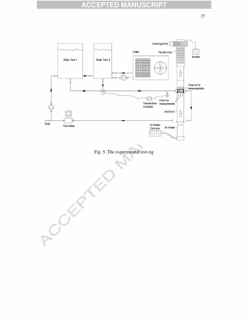
A schematic diagram of the test-rig is shown in Fig. 5, where the air heater, the
wind-tunnel, the chiller, the water tanks and the heat exchanger model are also shown,
together with the measurement positions upstream and downstream of the heat
exchanger.
Fig. 5. The experimental test-rig
The latter have been chosen to be 40mm upstream the model and 30mm
downstream the model. The two positions were the same for both the velocity and
pressure measurements. Especially for the cold medium (water), a closed loop was used
with two water tanks connected with manifolds to the heat exchanger. For the water
circulation, two small pumps were used, a triode mixing electrovalve and an
electromagnetic flow-meter. In order to have a comparative relation for the pressure
drop law with and without heat transfer phenomena, two sets of pressure drop
measurements have been carried-out, the first with no heat transfer (isothermal) and the

ACCEPTED MANUSCRIPT
8
second one with heat transfer (anisothermal). Additionally, regarding the inlet
conditions of the heated air, a variety of imposed conditions have been used which were
strongly related to the hot gas flow development inside the exhaust nozzle and to the
manner that it enters the heat exchanger installation. In a preliminary, simplistic CFD
numerical modeling [16] it was shown that the hot gas does not have a specific and
preferable direction as it enters the heat exchanger, thus, it has been decided to test as
many as possible inlet conditions. During the experiment, this has been modeled by
applying various inlet flow angles for various mass flow rates. The various inlet
conditions regarding the flow angle towards the heat exchanger have been obtained with
the use of 49 specific inlet ducts, which led to a range of combined angles of attack,
aa and inclination, ia , as defined in Fig. 6.
Fig. 6. Definitions of angle of attack and inclination
The values of the inlet air velocity were specified through the adjustment of the
wind-tunnel mass flow rates, the latter being controlled by a small centrifugal blower
installed at the exit of the wind-tunnel. For the anisothermal measurements, the air
temperatures were set to specific values according to the operating conditions and were
controlled by the adjustment of the air heater power. Additionally, the temperature
difference through the heat exchanger was controlled by the chiller power. Before
starting the measurements for each set corresponding to the anisothermal conditions, a
certain time interval was needed in order to have a stable and constant temperature
difference through the heat transfer process between the heat exchanger and the hot air.

ACCEPTED MANUSCRIPT
9
2.1 Measurement devices and accuracy
The pressure and velocity measurements were carried-out using a 3-hole probe
and a Pitot-static tube, capable to carry out measurements for the total and static
pressure and, also, for the velocity and flow angle. The 3-hole probe and the Pitot tube
have an accuracy of 2% referring to the dynamic pressure measurements, which leads to
a maximum error of 2Pa. The 3-hole probe is connected to a digital manometer, which
has an accuracy of 0.05% resulting-in a maximum error of 2Pa. The accuracy in the
angle of attack and angle of inclination has been estimated at ±1o as presented at the
work of Missirlis et al. [15] and the calibration procedure was the same with the one
presented by Morisson et al. [17] and Yasar and Carpinioglou [18]. The accuracy of the
positioning mechanism for the both the 3-hole probe and the Pitot tube is 0.25mm.
During the pressure drop measurements it was necessary that the measurements would
be carried out in such a way that would correspond to the average behavior of the heat
exchanger. For this reason, and since the heat exchanger geometry is composed of
numerous tubes with elliptic profile creating high and low velocity regions downstream
the heat exchanger, it was necessary to proceed to a measurement step dependency
study so as to find out and use the most appropriate measurement step.
At the initial stage of this work, preliminary measurements were carried out with
varying measurement steps at the normal direction. For the inlet position, where the
flow is expected to be relatively uniform, the measurement steps of 5, 10 and 15mm
were used. However, for the outlet position, where the flow is in the wake regions of the
elliptic tubes, much smaller values for the measurement step were used i.e., 0.5, 1, 1.5,
2, 2.5, 3 and 4 mm. The comparison of the average flow quantities, total and static
pressure and velocity components, as they were derived for each case with a different

ACCEPTED MANUSCRIPT
10
measurement step showed that in order to achieve values independent of the
measurement step, the measurement step at the inlet position should be selected equal or
less than 10mm while the measurement step at the outlet position should be selected
equal or less than 2.5mm. Thus, the measurement step for the inlet position was chosen
equal to 5mm while the one corresponding to the outlet position was chosen equal to
2mm. The selection of these step values provided an accuracy corresponding to less
than 1Pa for the total and static pressure values and to approximately 0.01m/s for the
velocity magnitude.
For the air temperature measurements, a K-type thermocouple was used with an
error of ± 1.2oC. For the water temperature measurements, a Platinum Resistance
Thermometers PT100 thermocouple was used with a resistance of 100 Ohms at 0oC and
138.4 Ohms at 100oC. The thermocouple provides a linear relationship between the
resistance and the water temperature leading to an error of ± 0.3oC. The volumetric
flow rate was measured with a MAGFLOW 5100W flowmeter with an average error of
0.5% for the range of the cold water flow rates applied to the experiment.
During the preliminary measurements, some problems appeared with
condensation of the air on the external surface of the heat exchanger tubes caused by the
ambient air humidity. Since the condensation process could affect the quality of the
measurements, two dehumidifiers were used in order to make sure that no condensation
would occur on the heat exchanger tubes. For all the sets of measurements, the relative
humidity was ranging from 34 to 39%.
ACCEPTED MANUSCRIPT
11
3. Experimental results
The aim of this work is the derivation of the pressure drop through the heat
exchanger by investigating also the effect of the heat transfer on the pressure drop. The
experiments were carried-out without heat transfer (isothermal study) and with heat
transfer (anisothermal study). For the isothermal study, measurements for four sets of
different inlet air temperature have been carried out, corresponding to Tair,in=20oC,
Tair,in=40oC, Tair,in=60oC, Tair,in=80oC (Tair,in= Tair,out) and for a range of mass flow rates
starting from 0.015kg/s up to 0.037kg/s. Only in the isothermal model with Tair,in=20oC
(Fig. 7) the maximum mass flow rate is 0.072kg/s. Since the fluid velocity varies along
its path it is necessary to select a reference velocity in order to define the Reynolds
number. According to the suggestions of Umeda and Yang [19], the reference velocity
maxU is based on the minimum free area available for fluid flow minA per unit length of
the tube length D , regardless if the minimum area occurs in the transverse or diagonal
opening. Thus, the Reynolds number is defined as: maxReU D
v= where ν is the fluid
kinematic viscosity. The laminar-flow range is for Re 200< and the turbulent-flow
range for Re 6000> with the transition-flow range being between 200 Re 6000< < [19].
For the experimental measurements of the present work, the corresponding Reynolds
numbers are in the range of 280 and 921 and, consequently, the flow is within the
transitional regime.
The anisothermal measurements have been carried-out for the same inlet mass
flow rate range and for two air temperature differences, Tair,in=60oC and Tair,out=31oC,
Tair,in=80oC and Tair,out=33oC. The temperature of the cold water was varying from 9 to
17oC depending on the air mass flow rate and the selected outlet air temperature. The

ACCEPTED MANUSCRIPT
12
experimental conditions are listed and presented in Table 1. For all cases of
measurements, isothermal and anisothermal, the evolution of the total and static
pressure drop are rather similar because the dynamic pressure is very small. Therefore
only the total pressure curves will be presented.
Table 1. Experimental conditions of air and water
3.1 Isothermal measurement conditions
Figure 7 shows the total pressure drop for the isothermal case with an inlet air
temperature equal to 20oC and for seven different angles of attack in the ranging from 0o
up to 60o. For this set of measurements, the angle of inclination was set to zero. In the
same figure, the curves represent the polynomial fitting of the measured data for each
case. From these measurements, it is clearly shown that for the same inlet air mass flow
rate, there is an increase of the pressure drop and this can be attributed to the effect of
the angle of attack on an elliptic-shaped airfoil. As already written, each tube of the heat
exchanger has an elliptic shape. As the air-flow enters with a non-zero angle of attack,
there is a significant increase of the pressure losses. As the flow continues to pass
around the tubes, it tends to be straightened by the passages through the heat
exchangers, but in any case, in the region of the first row of tubes, the flow is starting to
form downstream large wakes, which increasingly affect the pressure drop through the
heat exchanger. This observation is supported by our first preliminary CFD modeling,
Missirlis et al. [16], where the flow through the heat exchanger has been investigated
using some preliminary but very detailed isothermal measurements on an individual
heat exchanger package. The fitting curves, are based on second order polynomials,

ACCEPTED MANUSCRIPT
13
having a general expression of the form: cmbmap ++=∆ &&2 where �p refers to the
pressure drop, m& to the inlet mass flow rate and a, b, c to the coefficients from the
polynomial curve fitting.
Fig. 7. Total pressure drop for isothermal-1 case for seven angles of attack and 0° angle
of inclination
During the experiments, the effect of the angle of inclination has been also
investigated by performing measurements for the isothermal case of the 20oC having an
angle of attack equal to zero. Figure 8 show the variation of the total pressure drop, for
various inlet air mass flow rates and for seven angles of inclinations ranging from 0o up
to 60o. Additionally, in the same figure, the curve representing the polynomial fitting of
the pressure drop variation for the zero angle of attack and angle of inclination
combination is also shown. As it can be seen, the measurements for all the angles of
inclination are concentrated in a region very close to the curve representing the 0o-0o
distribution, leading to the conclusion that the effect of the angle inclination to the
pressure drop is negligible.
Fig. 8. Total pressure drop for isothermal-1 case for seven angles of inclination and 0°
angle of attack
In the previous section, we concluded that the effect of a non-zero angle of
attack is quite significant since there is an increase of the pressure drop. Alternatively,
the effect of the inlet air temperature to the pressure drop, having a constant inlet angle,
ACCEPTED MANUSCRIPT
14
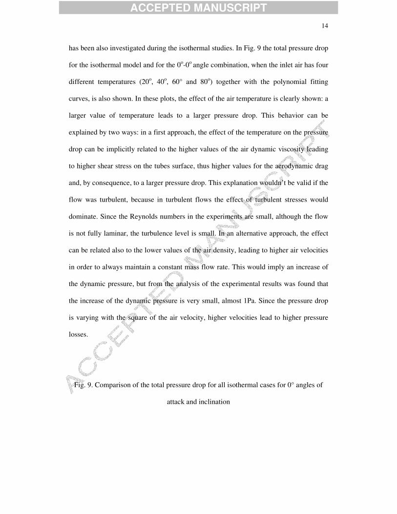
has been also investigated during the isothermal studies. In Fig. 9 the total pressure drop
for the isothermal model and for the 0o-0o angle combination, when the inlet air has four
different temperatures (20o, 40o, 60° and 80o) together with the polynomial fitting
curves, is also shown. In these plots, the effect of the air temperature is clearly shown: a
larger value of temperature leads to a larger pressure drop. This behavior can be
explained by two ways: in a first approach, the effect of the temperature on the pressure
drop can be implicitly related to the higher values of the air dynamic viscosity leading
to higher shear stress on the tubes surface, thus higher values for the aerodynamic drag
and, by consequence, to a larger pressure drop. This explanation wouldn’t be valid if the
flow was turbulent, because in turbulent flows the effect of turbulent stresses would
dominate. Since the Reynolds numbers in the experiments are small, although the flow
is not fully laminar, the turbulence level is small. In an alternative approach, the effect
can be related also to the lower values of the air density, leading to higher air velocities
in order to always maintain a constant mass flow rate. This would imply an increase of
the dynamic pressure, but from the analysis of the experimental results was found that
the increase of the dynamic pressure is very small, almost 1Pa. Since the pressure drop
is varying with the square of the air velocity, higher velocities lead to higher pressure
losses.
Fig. 9. Comparison of the total pressure drop for all isothermal cases for 0° angles of
attack and inclination
ACCEPTED MANUSCRIPT
15
3.2 Anisothermal measurement conditions
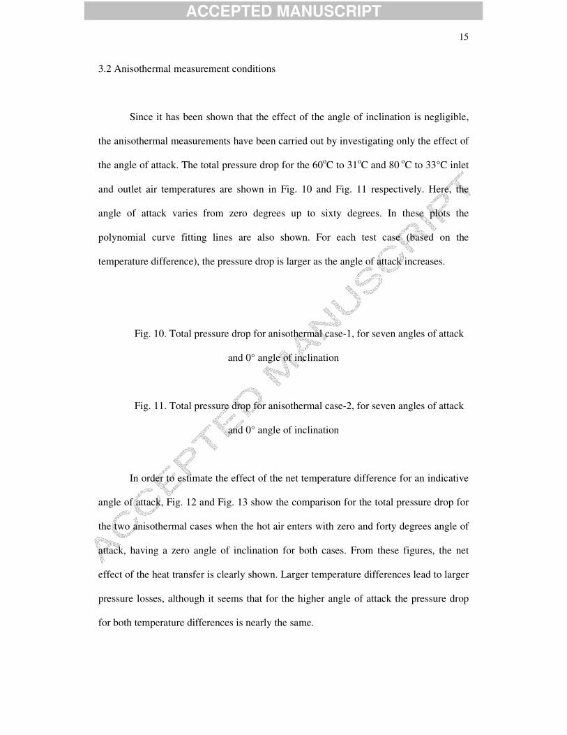
Since it has been shown that the effect of the angle of inclination is negligible,
the anisothermal measurements have been carried out by investigating only the effect of
the angle of attack. The total pressure drop for the 60oC to 31oC and 80 oC to 33°C inlet
and outlet air temperatures are shown in Fig. 10 and Fig. 11 respectively. Here, the
angle of attack varies from zero degrees up to sixty degrees. In these plots the
polynomial curve fitting lines are also shown. For each test case (based on the
temperature difference), the pressure drop is larger as the angle of attack increases.
Fig. 10. Total pressure drop for anisothermal case-1, for seven angles of attack
and 0° angle of inclination
Fig. 11. Total pressure drop for anisothermal case-2, for seven angles of attack
and 0° angle of inclination
In order to estimate the effect of the net temperature difference for an indicative
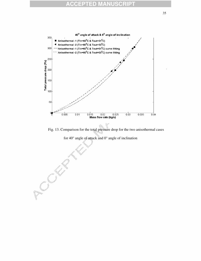
angle of attack, Fig. 12 and Fig. 13 show the comparison for the total pressure drop for
the two anisothermal cases when the hot air enters with zero and forty degrees angle of
attack, having a zero angle of inclination for both cases. From these figures, the net
effect of the heat transfer is clearly shown. Larger temperature differences lead to larger
pressure losses, although it seems that for the higher angle of attack the pressure drop
for both temperature differences is nearly the same.

ACCEPTED MANUSCRIPT
16
Fig. 12. Comparison for the total pressure drop for the two anisothermal cases for 0°
angles of attack and inclination
Fig. 13. Comparison for the total pressure drop for the two anisothermal cases for 40°
angle of attack and 0° angle of inclination
3.3 Intercomparison between isothermal and anisothermal measurements
So far it has been shown that two major parameters govern the pressure losses of
the flow through the heat exchanger: the angle of attack and the inlet temperature of the
hot air. The effect of the heat transfer mechanism, compared to the cases when no heat
transfer occurs, can be illustrated by the following plots for the total pressure presented
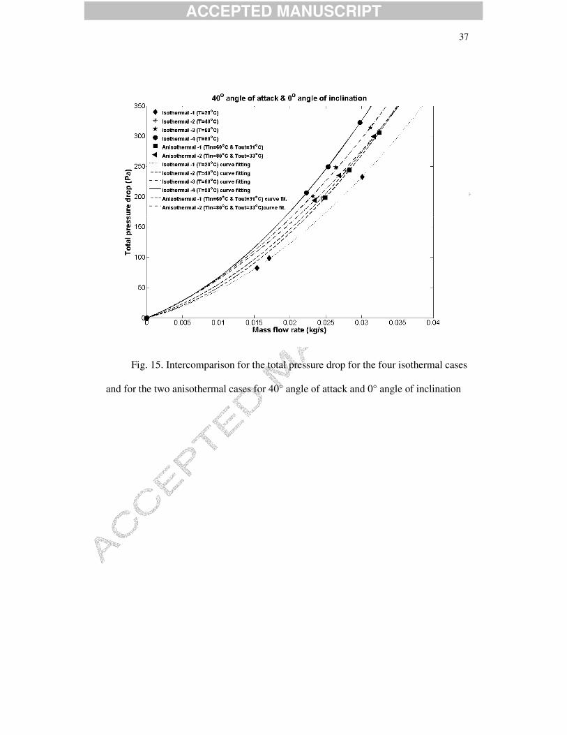
in Fig. 14 and Fig. 15. Figure 14 refers to all the cases investigated (iso- and
anisothermal) having a zero angle of attack and inclination while Fig. 15 to the cases
having 40o angle of attack and a zero angle of inclination. The polynomial curve fitting
lines are also shown. For both figures, the general trend is that the higher angle of attack
together with the higher inlet temperature leads to larger values of pressure drop. On the
other hand, a detailed investigation of these data shows that there is also an effect of the
temperature difference when heat transfer is on (clearly shown in the previous section).
For the isothermal case with inlet air temperature equal to 80oC, the pressure drop is
larger than the one of the anisothermal case, which has the same inlet air temperature
but the air is cooled. For both angles of attack, i.e. zero and 40o, when the air has a
constant high inlet temperature the largest values for the pressure drop are presented.
This holds also for the corresponding isothermal and anisothermal cases with inlet air

ACCEPTED MANUSCRIPT
17
temperature equal to 60oC. This behavior can be related, in the same manner as it was
done for the isothermal cases, to the variation of the density and the viscosity. As a
general remark, it is clearly shown that air-cooling leads to lower pressure drop. This
has a direct effect on the operation of the heat exchanger inside the exhaust nozzle and
the imposed pressure drop downstream the turbine of the aero engine.
Fig. 14. Intercomparison for the total pressure drop for the four isothermal cases and for
the two anisothermal cases for 0° angles of attack and inclination
Fig. 15. Intercomparison for the total pressure drop for the four isothermal cases and for
the two anisothermal cases for 40° angle of attack and 0° angle of inclination
4. CONCLUSIONS
In this work, an experimental attempt was made to correlate the pressure drop through a
specific type heat exchanger for aero engine applications with two main parameters: the
inlet temperature and the angle of attack and inclination of the hot-air mainstream
direction. These parameters have been investigated firstly by carrying-out isothermal
measurements (with no heat transfer). Additionally, the effect of heat transfer on the
pressure drop has been investigated, by carrying-out anisothermal measurements (with
heat transfer). All these parameters are of critical importance since the heat exchanger is
designed to operate as a recuperator downstream the aero engine by cooling the hot
exhaust gas. Especially for the angles of attack and inclination, their role is very
important since the flow development downstream the engine does not have a

ACCEPTED MANUSCRIPT
18
prescribed direction and enters in the heat exchanger by having various angles of attack
and inclination. The detailed measurements showed that:
1) There is a direct correlation of the pressure drop with the inlet air temperature.
Higher temperatures lead to higher pressure drops, for the same inlet air mass flow
rate.
2) The angle of attack plays also a major role to the pressure drop since; higher angles
of attack lead to higher pressure drops.
3) The heat transfer rate regarding the cooling of the hot air is also a significant
parameter. As the temperature difference between the hot and the cooled air
increases, the pressure losses are also increasing.
Based on these conclusions, the next step is to derive an integrated law for the
pressure drop through this type of heat exchanger, which will be able to correlate these
three main parameters with the flow parameters (temperature, density, inlet velocity and
viscosity). The derivation of such a pressure drop will allow the modeling of the
operation of the heat exchangers inside the exhaust nozzle by creating “pressure drop
zones” instead of modeling in detail every single flow-passage and the whole geometry
of the heat exchanger.

ACCEPTED MANUSCRIPT
19
Acknowledgments
This paper is part of the 03ED research project, implemented within the framework of
the “Reinforcement Programme of Human Research Manpower” (PENED) and co-
financed by National and Community Funds 25% from the Greek Ministry of
Development-General Secretariat of Research and Technology and 75% from E.U.-
European Social Fund. A part of this project has been also funded by MTU Aero
Engines GmbH.
References
[1] L.M.K. Boetler, A.G. Guibert, F.E. Romie, V.D. Sanders, J.M. Rademacher, An
investigation of aircraft heaters XXXI-Summary of laboratory testing of several
exhaust-gas and air heat exchangers, University of California, National Advisory
Committee for Aeronautics, Technical Note (1949) 1455.
[2] H. Brauer, Compact Heat Exchangers, Chem. Process Eng., (1964) 451-460.
[3] F. Schulenberg,, Finned elliptical tubes and their applications in air-cooled heat
exchangers. J. Eng. Ind. 88 (1966) 179–190
[4] S.N. Bordalo, F.E.M. Saboya, Pressure drop coefficients for elliptic and circular
sections in one, two and three row arrangements of plate fin and tube heat exchanger, J.
Braz. Soc. Mech. Sci. XXI (4) (1999) 600-610.

ACCEPTED MANUSCRIPT
20
[5] S.M. Saboya, F.E.M. Saboya, Experiments on elliptic sections in one and two row
arrangements of plate fin and tube heat exchanger. Experiment. Therm. Fluid Sci. 24
(2001) 67–75.
[6] L.A.O. Rocha, F.E.M Saboya, J.V.C Vargas, A comparative study of elliptical and
circular sections in one and two row tubes and plate fin heat exchangers. Int. J. Heat
Fluid Flow 18 (1997) 247–252.
[7] D. Bouris, E. Konstantinidis, S. Balavani, D. Castiglia, G. Bergeles, Design of a
novel, intensified heat exchanger for reduced fouling rates, Int. J. Heat and Mass
Transfer 48 (2004) 3817-3832.
[8] G.A. Longo, A. Gasparella, Heat transfer and pressure drop during HFC refrigerant
vaporisation inside a brazed plate heat exchanger, International Journal of Heat and
Mass Transfer 50 (2007) 5194-5203.
[9] B.M. Jacimovic, S.B. Genic, B.R. Latinovic, Research on the air pressure drop in
plate finned tube heat exchanger, Int. J. Refrigeration 29 (2006) 1138-1143.
[10] K. Broichhausen, H. Scheugenpflug, Ch. Mari, A. Barbot, Clean The European
Initiative Towards Ultra Low Emission Engines, ICAS 2000, Harrogate, UK, 2000.
[11] G. Wilfert, B. Masse, Technology integration in a low emission heat exchanger
engine, in: Proceedings of the 8th CEAS European Propulsion Forum, Nottingham, UK,
2001.

ACCEPTED MANUSCRIPT
21
[12] <http://www.mtu.de/en/technik/clean/index.html>
[13] C. Ruixian, J. Lixia, Analysis of the recuperative gas turbine cycle with a
recuperator located between turbines, Appl. Therm. Eng. 26 (2006) 89–96.
[14] K. Yakinthos, D. Missirlis, A. Palikaras, P. Storm, B. Simon, A. Goulas,
Optimization of the design of recuperative heat exchangers in the exhaust nozzle of an
aero engine, Applied Mathematical Modelling 31 (2007) 2524-2541
[15] D. Missirlis, K. Yakinthos, A. Palikaras, K. Katheder, A. Goulas, Experimental and
numerical investigation of the flow field through a heat exchanger for aero-engine
applications, Int. J. of Heat and Fluid Flow 26 (2005) 440-458.
[16] D. Missirlis, K. Yakinthos, P. Storm, A. Goulas, Modeling pressure drop of
inclined flow through a heat exchanger for aero-engine applications, Int. J. of Heat and
Fluid Flow 28 (2007) 512-515.
[17] G.L. Morrison, M.T. Schobeiri, K.R. Pappu, Five-hole pressure probe analysis
technique, Flow Measurements and Instrumentation 9 (1998) 153-158.
[18] M.Y. Gundogdu, M.O. Carpinlioglu, A multi-tube pressure probe calibration
method for measurements of mean flow parameters in swirling flows, Flow
Measurements and Instrumentation 9 (1998) 243-248.

ACCEPTED MANUSCRIPT
22
[19] S. Umeda and W.-J. Yang, Interaction of von Karman vortices and intersecting
main streams in staggered tube bundles, Experiments in Fluid 26 (1999) 389-396.

ACCEPTED MANUSCRIPT
23
Fig. 1. The recuperative aero engine

ACCEPTED MANUSCRIPT
24
Fig. 2. Meridional view of the exhaust nozzle

ACCEPTED MANUSCRIPT
25
Fig. 3. The heat exchanger and the U-shaped elliptic profiled tubes

ACCEPTED MANUSCRIPT
26
Fig. 4. The test-rig with the heat exchanger
ACCEPTED MANUSCRIPT
27
Fig. 5. The experimental test-rig

ACCEPTED MANUSCRIPT
28
Fig. 6. Definitions of angle of attack and inclination

ACCEPTED MANUSCRIPT
29
Fig. 7. Total pressure drop for isothermal-1 case for seven angles of attack and 0° angle
of inclination

ACCEPTED MANUSCRIPT
30
Fig. 8. Total pressure drop for isothermal-1 case for seven angles of inclination and 0°
angle of attack

ACCEPTED MANUSCRIPT
31
Fig. 9. Comparison of the total pressure drop for all isothermal cases for 0° angles of
attack and inclination

ACCEPTED MANUSCRIPT
32
Fig. 10. Total pressure drop for anisothermal case-1, for seven angles of attack
and 0° angle of inclination

ACCEPTED MANUSCRIPT
33
Fig. 11. Total pressure drop for anisothermal case-2, for seven angles of attack
and 0° angle of inclination

ACCEPTED MANUSCRIPT
34
Fig. 12. Comparison for the total pressure drop for the two anisothermal cases for 0°
angles of attack and inclination
ACCEPTED MANUSCRIPT
35
Fig. 13. Comparison for the total pressure drop for the two anisothermal cases
for 40° angle of attack and 0° angle of inclination

ACCEPTED MANUSCRIPT
36
Fig. 14. Intercomparison for the total pressure drop for the four isothermal cases and for
the two anisothermal cases for 0° angles of attack and inclination
ACCEPTED MANUSCRIPT
37
Fig. 15. Intercomparison for the total pressure drop for the four isothermal cases
and for the two anisothermal cases for 40° angle of attack and 0° angle of inclination

ACCEPTED MANUSCRIPT
38
Measurements Cases
Tair,in (°C)
Tair,out (°C)
�� (°C)
Air mass flow range
(kg/s)
Twater,in
(°C)
Water mass flow
range (lit/h)
20 20 0 - 40 40 0 - 60 60 0 -
Isothermal
80 80 0 - 60 31 29 14-17 Heat Transfer 80 33 47
0.015-0.037
9-12
715-910
Table 1. Experimental conditions of air and water