Embed Size (px)
Citation preview
BRAZILIAN JOURNAL OF PETROLEUM AND GAS | v. 8 n. 3 | p. 109-117 | 2014 | ISSN 1982-0593
109
THE EFFECT OF OIL CONCENTRATION ON THE SEPARATION EFFICIENCY OF WATER/OIL MIXTURES IN A HYDROCYCLONE
a Luna, F. D. T. 1; a Araújo, M. V. ; a Farias Neto, S. R.; b Lima, A. G. B.; b Barbosa, E. S.
a Department of Chemical Engineering, Federal University of Campina Grande, Campina Grande, Brazil
b Department of Mechanical Engineering, Federal University of Campina Grande, Campina Grande, Brazil
ABSTRACT This study aims to evaluate a new proposed device for separating oil / water mixtures, which has an operating principle similar to a traditional hydrocyclone. Modifications in the geometry and in the operation principle of the equipment have been suggested to improve the separation efficiency of the fluids, because these parameters have a decisive effect on the flow behavior inside the equipment and on fluid separation. The ANSYS CFX software was used as a simulation tool. The changes in oil concentration feed influenced the efficiency.
KEYWORDS multiphase flow; cyclonic Separator; CFD; oily water
1 To whom all correspondence should be addressed.
Address: Department of Chemical Engineering, Federal University of Campina Grande, Av: Aprígio Veloso, 882, Bodocongó, Campina Grande, Brazil Zip Code: 58429-900|Telephone: (55) 11 95436-1365 |e-mail: [email protected] doi:10.5419/bjpg2014-0010
BRAZILIAN JOURNAL OF PETROLEUM AND GAS | v. 8 n. 3 | p. 109-117 | 2014 | ISSN 1982-0593
110
1. INTRODUCTION
The disposal of industrial effluents into the environment, especially produced water by the oil industry, is a problematic that has attracted the attention of engineers and researchers. The presence of oil in these waters is a common situation and its disposal should meet the specifications regulated by environmental agencies in each country (Barbosa, 2011).
The oil industry has employed different separation processes such decantation, coagulation/ flocculation, filtration, adsorption, centrifugation, heat treatment, to separate water/oil mixtures. Among the different equipments used in the process, the hydrocyclone can be highlighted. Advantages presented by the cyclone include having a high- processing capacity, offering lower units and short residence times, and presenting a low cost of implantation and maintenance (Alves, 2012).
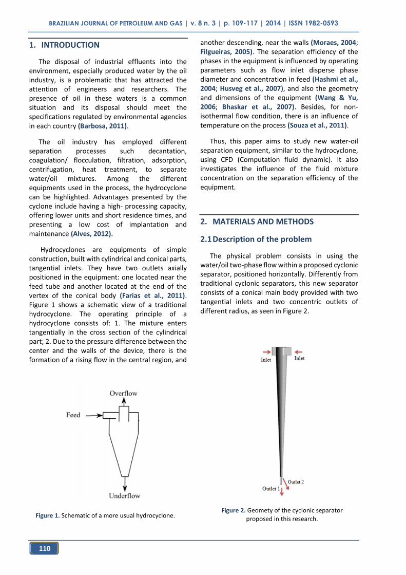
Hydrocyclones are equipments of simple construction, built with cylindrical and conical parts, tangential inlets. They have two outlets axially positioned in the equipment: one located near the feed tube and another located at the end of the vertex of the conical body (Farias et al., 2011). Figure 1 shows a schematic view of a traditional hydrocyclone. The operating principle of a hydrocyclone consists of: 1. The mixture enters tangentially in the cross section of the cylindrical part; 2. Due to the pressure difference between the center and the walls of the device, there is the formation of a rising flow in the central region, and
another descending, near the walls (Moraes, 2004; Filgueiras, 2005). The separation efficiency of the phases in the equipment is influenced by operating parameters such as flow inlet disperse phase diameter and concentration in feed (Hashmi et al., 2004; Husveg et al., 2007), and also the geometry and dimensions of the equipment (Wang & Yu, 2006; Bhaskar et al., 2007). Besides, for non-isothermal flow condition, there is an influence of temperature on the process (Souza et al., 2011).
Thus, this paper aims to study new water-oil separation equipment, similar to the hydrocyclone, using CFD (Computation fluid dynamic). It also investigates the influence of the fluid mixture concentration on the separation efficiency of the equipment.
2. MATERIALS AND METHODS
2.1 Description of the problem
The physical problem consists in using the water/oil two-phase flow within a proposed cyclonic separator, positioned horizontally. Differently from traditional cyclonic separators, this new separator consists of a conical main body provided with two tangential inlets and two concentric outlets of different radius, as seen in Figure 2.
Figure 1. Schematic of a more usual hydrocyclone.
Figure 2. Geomety of the cyclonic separator proposed in this research.
BRAZILIAN JOURNAL OF PETROLEUM AND GAS | v. 8 n. 3 | p. 109-117 | 2014 | ISSN 1982-0593
111
2.2 Computational domain
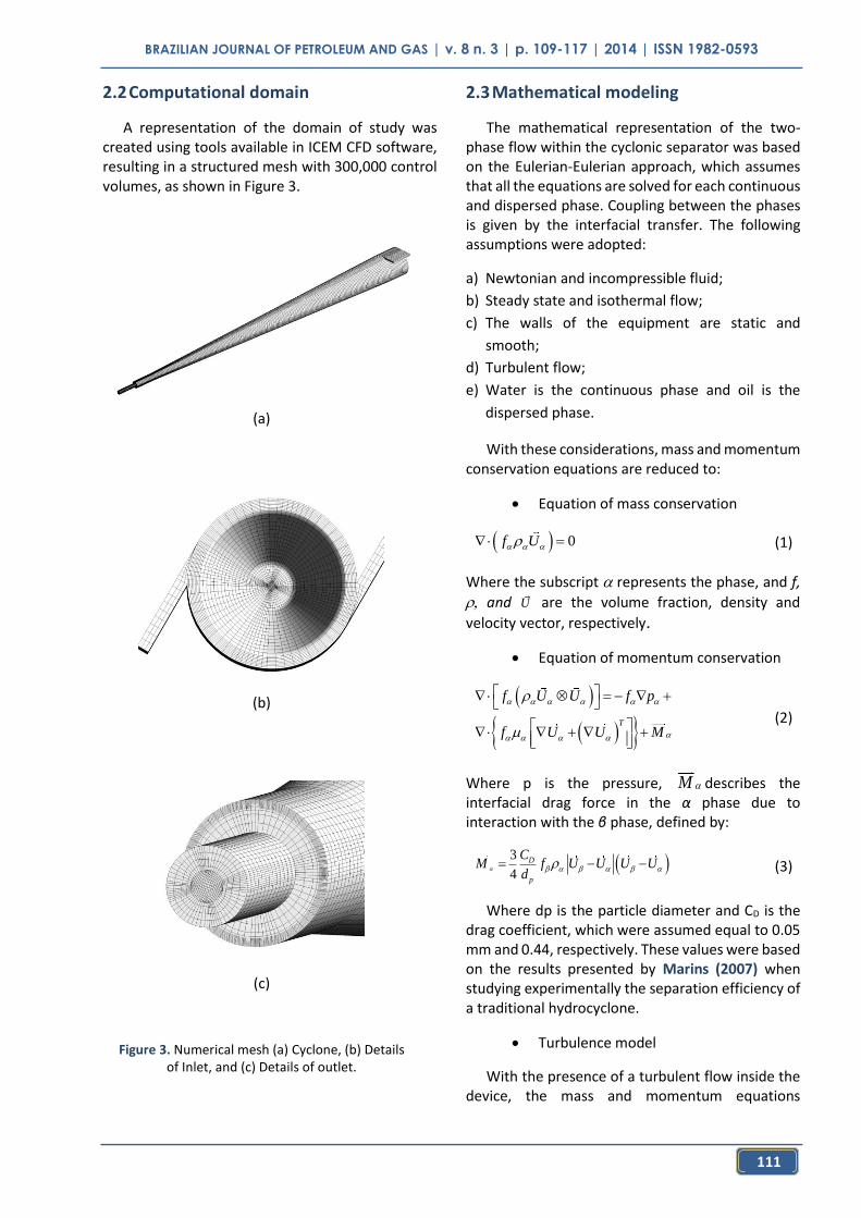
A representation of the domain of study was created using tools available in ICEM CFD software, resulting in a structured mesh with 300,000 control volumes, as shown in Figure 3.
2.3 Mathematical modeling
The mathematical representation of the two-phase flow within the cyclonic separator was based on the Eulerian-Eulerian approach, which assumes that all the equations are solved for each continuous and dispersed phase. Coupling between the phases is given by the interfacial transfer. The following assumptions were adopted:
a) Newtonian and incompressible fluid;
b) Steady state and isothermal flow;
c) The walls of the equipment are static and
smooth;
d) Turbulent flow;
e) Water is the continuous phase and oil is the
dispersed phase.
With these considerations, mass and momentum conservation equations are reduced to:
Equation of mass conservation
0f U (1)
Where the subscript represents the phase, and f,
and are the volume fraction, density and
velocity vector, respectively.
Equation of momentum conservation
T
f U U f p
f U U M
(2)
Where p is the pressure, M describes the interfacial drag force in the α phase due to interaction with the β phase, defined by:
3
4D
p
CM f U U U U
d
(3)
Where dp is the particle diameter and CD is the drag coefficient, which were assumed equal to 0.05 mm and 0.44, respectively. These values were based on the results presented by Marins (2007) when studying experimentally the separation efficiency of a traditional hydrocyclone.
Turbulence model
With the presence of a turbulent flow inside the device, the mass and momentum equations
U
(a)
(b)
(c)
Figure 3. Numerical mesh (a) Cyclone, (b) Details of Inlet, and (c) Details of outlet.
BRAZILIAN JOURNAL OF PETROLEUM AND GAS | v. 8 n. 3 | p. 109-117 | 2014 | ISSN 1982-0593
112
(Equations 1 and 2) aren’t able to adequately predict the oscillations arising from this phenomenon. In addition to the equations of conservation, it is necessary to use a suitable turbulence model.
Therefore, the RNG kturbulence model was used to describe the turbulent behavior of the envolved phases in flow. Barbosa (2011) showed that this model was the best representative of the flow inside a traditional hydrocyclone.
This model consists of the following equations:
RNG
Tk
k
Uk U k p
(4)
1 2T
RNG RNG
RNG
U C k Ck
(5)
Where k is the turbulent kinetic energy, is the turbulent dissipation, which is the rate at which the
velocity fluctuations dissipate, and is the turbulent viscosity obtained by:
2
T
kC
(6)
being Ca constant.
In the Equation 4 pk is the production of turbulence due to the viscous and buoyancy forces or shear production, defined by:
T
k T kbp U U U p
(7)
Being pkb the term of thrust producing, modeled as follows:
Tkbp g
(8)
Where σρ is a constant equal to 1.
The empirical constants have the following
values: Cμ = 0.09; σkRNG = 0.7179; σRNG = 0.7179; and
RNG = 1.68. Besides,
1 3
14.38
1.421RNG
RNG
C
(9)
Where and RNG are additional constants of the model.
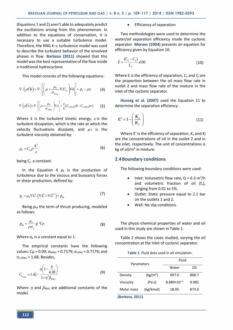
Efficiency of separation
Two methodologies were used to determine the water/oil separation efficiency inside the cyclonic separator. Moraes (2004) presents an equation for efficiency given by Equation 10.
( )100
f o
f
C CE x
C
(10)
Where E is the efficiency of separation, Co and Cf are the proportion between the oil mass flow rate in outlet 2 and mass flow rate of the mixture in the inlet of the cyclonic separator.
Husveg et al. (2007) used the Equation 11 to determine the separation efficiency.
1 o
f
KE
K
(11)
Where E' is the efficiency of separation, Ko and Kf are the concentrations of oil in the outlet 2 and in the inlet, respectively. The unit of concentrations is kg of oil/m³ in mixture.
2.4 Boundary conditions
The following boundary conditions were used:
Inlet: Volumetric flow rate, Q = 6.3 m3/h and volumetric fraction of oil (fo), ranging from 0.01 to 5%.
Outlet: Static pressure equal to 2.1 bar on the outlets 1 and 2.
Wall: No slip conditions.
The physic-chemical properties of water and oil used in this study are shown in Table 1.
Table 2 shows the cases studied, varying the oil concentration at the inlet of cyclonic separator.
Table 1. Fluid data used in all simulation.
Parameters Fluid
Water Oil
Density (kg/m3) 997.0 868.7
Viscosity (Pa.s) 8.889×10⁻⁴ 0.985
Molar mass (kg/kmol) 18.05 873.0
(Barbosa, 2011)
BRAZILIAN JOURNAL OF PETROLEUM AND GAS | v. 8 n. 3 | p. 109-117 | 2014 | ISSN 1982-0593
113
3. RESULTS AND DISCUSSION
The numerical results of the simulations for the cases described in Table 2 are analyzed by flow lines, pressure field, velocity profiles, and oil concentration field within the cyclonic separator.
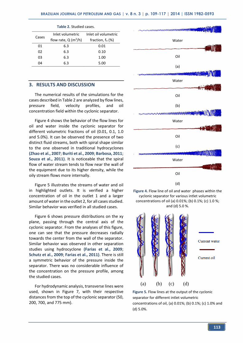
Figure 4 shows the behavior of the flow lines for oil and water inside the cyclonic separator for different volumetric fractions of oil (0.01, 0.1, 1.0 and 5.0%). It can be observed the presence of two distinct fluid streams, both with spiral shape similar to the one observed in traditional hydrocyclones (Zhao et al., 2007; Buriti et al., 2009; Barbosa, 2011; Souza et al., 2011). It is noticeable that the spiral flow of water stream tends to flow near the wall of the equipment due to its higher density, while the oily stream flows more internally.
Figure 5 illustrates the streams of water and oil in highlighted outlets. It is verified a higher concentration of oil in the outlet 1 and a larger amount of water in the outlet 2, for all cases studied. Similar behavior was verified in all studied cases.
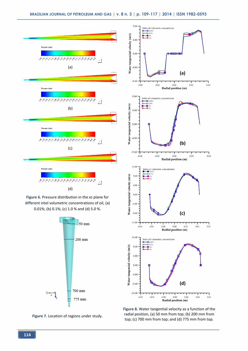
Figure 6 shows pressure distributions on the xy plane, passing through the central axis of the cyclonic separator. From the analyses of this figure, one can see that the pressure decreases radially towards the center from the wall of the separator. Similar behavior was observed in other separation studies using hydrocyclone (Farias et al., 2009; Schutz et al., 2009; Farias et al., 2011). There is still a symmetric behavior of the pressure inside the separator. There was no considerable influence of the concentration on the pressure profile, among the studied cases.
For hydrodynamic analysis, transverse lines were used, shown in Figure 7, with their respective distances from the top of the cyclonic separator (50, 200, 700, and 775 mm).
Water
Oil
(a)
Water
Oil
(b)
Water
Oil
(c)
Water
Oil
(d)
Figure 4. Flow line of oil and water phases within the cyclonic separator for various intlet volumetric
concentrations of oil (a) 0.01%; (b) 0.1%; (c) 1.0 %; and (d) 5.0 %.
(a) (b) (c) (d)
Figure 5. Flow lines at the output of the cyclonic
separator for different intlet volumetric
concentrations of oil, (a) 0.01%; (b) 0.1%; (c) 1.0% and
(d) 5.0%.
Table 2. Studied cases.
Cases Inlet volumetric
flow rate, Q (m3/h)
Inlet oil volumetric
fraction, fo (%)
01 6.3 0.01
02 6.3 0.10
03 6.3 1.00
04 6.3 5.00
BRAZILIAN JOURNAL OF PETROLEUM AND GAS | v. 8 n. 3 | p. 109-117 | 2014 | ISSN 1982-0593
114
(a)
(b)
(c)
(d)
Figure 6. Pressure distribution in the xz plane for
different intel volumetric concentrations of oil, (a)
0.01%; (b) 0.1%; (c) 1.0 % and (d) 5.0 %.
Figure 7. Location of regions under study.
Figure 8. Water tangential velocity as a function of the radial position, (a) 50 mm from top; (b) 200 mm from top; (c) 700 mm from top; and (d) 775 mm from top.
(a)
(b)
(c)
(d)
BRAZILIAN JOURNAL OF PETROLEUM AND GAS | v. 8 n. 3 | p. 109-117 | 2014 | ISSN 1982-0593
115
Figure 8 shows the tangential velocity profile of water on the regions represented in the Figure 7. It is possible to notice that the amplitude of tangential velocity is not influenced significantly by the increase in oil concentration in the feed. However, the amplitude of this parameter has increased over the cyclonic separator for all cases studied. The symmetry in the velocity field can also be highlighted.
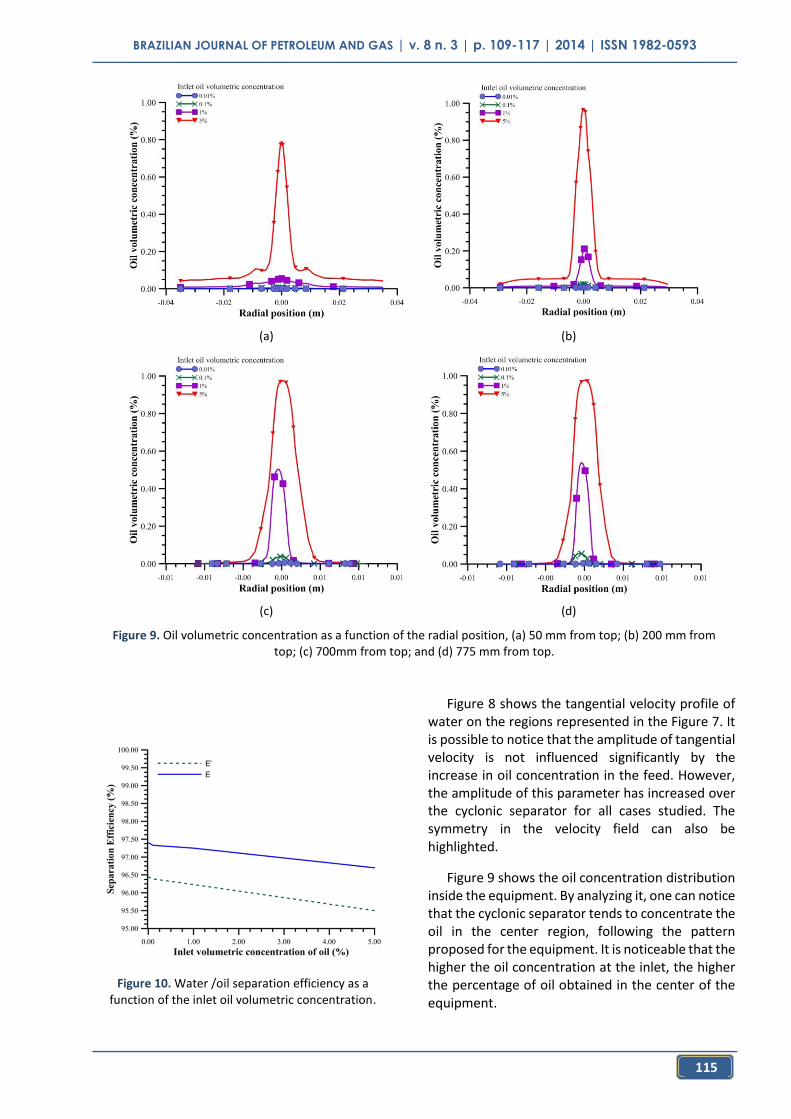
Figure 9 shows the oil concentration distribution inside the equipment. By analyzing it, one can notice that the cyclonic separator tends to concentrate the oil in the center region, following the pattern proposed for the equipment. It is noticeable that the higher the oil concentration at the inlet, the higher the percentage of oil obtained in the center of the equipment.
(a) (b)
(c) (d)
Figure 9. Oil volumetric concentration as a function of the radial position, (a) 50 mm from top; (b) 200 mm from top; (c) 700mm from top; and (d) 775 mm from top.
Figure 10. Water /oil separation efficiency as a function of the inlet oil volumetric concentration.
BRAZILIAN JOURNAL OF PETROLEUM AND GAS | v. 8 n. 3 | p. 109-117 | 2014 | ISSN 1982-0593
116
The separation efficiency was calculated using equations 10 and 11. Figure 10 shows these efficiency values as a function of the oil volumetric fraction in the inlet.
The results show that the efficiency values obtained with the two mathematical equations were different. Higher values were obtained when using equation 10 (efficiency E) for all studied cases. However, it is observed a similar behavior for efficiencies calculated by the two relationships; both give a short decay on the efficiency with the increase in oil concentration at the inlet. A similar behavior was observed by Hashmi et al.’s (2004) evaluation of the separation efficiencies for different oil concentrations in a hydrocyclone. The maximum efficiency achieved was 97.40% for the inlet oil concentration of 0.01%, when using Equation 10.
4. CONCLUSIONS
Based on the numerical results of the water/oil separation process using the cyclonic separator, it can be concluded that:
The oil tends to flow in the central region of the equipment, until be collected at the outlet 1;
Pressure and tangential velocity have symmetrical behavior inside the cyclonic separator;
The separation efficiency is not greatly influenced by varying the concentration of oil from 0.01 to 5% in the inlet;
The highest separation efficiency value obtained was 97.40%, given by the model proposed by Moraes (2004).
ACKNOWLEDGEMENTS
The authors thank CNPq, CAPES, FINEP, PETROBRAS, and ANP/PRH-25 (Brazilian Research Agencies) for financial support.
5. REFERENCES
Alves, J.V.B., Hydrocyclone for separating the water from residual oil refinery. Master dissertation in Chemical Engineering, Federal University of Rio de Janeiro, Brazil, 2012 (In Portuguese).
Barbosa, E.S., Geometric and Hydrodynamic aspects of a Hydrocyclone in Separation Process Sys-Multiphase: Application to Oil Industry. Doctoral thesis in Process Engineering. Federal University of Campina Grande, Campina Grande, Brazil, 2011 (In Portuguese).
Bhaskar, K.U; Murthy, Y.R; Ramakrishnan, N.; Srivastava, J.K; Sarkar, S.; Kumar, V., CFD validation for flyash particle classification in hydrocyclones. Minerals Engineering, v. 20, n.3, p. 290-302, 2007. http://dx.doi.org/10.1016/j.mineng.2006.10.009
Buriti, C.J.O. Farias, F.P.M, Farias Neto, S.R, Lima, A.G.B. Performance and numerical evaluation of the separation process water / heavy oil and ultraviscoso inside a hydrocyclone. V Brazilian Congress of P & D in Oil & Gas, 1-2, Fortaleza, Brazil, 2007.(In Portuguese).
Farias, F.P.M; Farias Neto, S. R; Lima, A. G. B.; Buriti, C. J. O.; Lima, W. C. P. The Effect of Droplet Diameter on the Separation of the Heavy-Oil from Water using Hydrocyclone CFD Simulation. III International Conference on Advanced Computational Engineering and Experimenting. ACE-X, Roma, Italy, 2009.
Farias, F. P. M.; Souza, J. S.; Lima, W.C.P.B.; Macêdo, A.C.; Farias Neto, S. R.; Lima, A.G.B. Influence of Geometric Parameters of the Hydrocyclone and Sand Concentration on the Water/Sand/Heavy-Oil Separation Process: Modeling and Simulation. The International Journal of Multiphysics, v. 5, n.3, p. 187-202, 2011. http://dx.doi.org/10.1260/1750-9548.5.3.187
Filgueiras, N. G. T. Modeling, Analysis and Control of a Separation Process Oil / water. Master dissertation in Chemical Engineering, COPPE/UFRJ, Rio de Janeiro, Brazil, 2005 (In Portuguese).
Hashmi, K. A.; Hamza, H. A.; Wilson, J. C. CANMET hydrocyclone: an emerging alternative for the treatment. Mineral Engineering, v. 17, n. 5, p. 643-649, 2004. http://dx.doi.org/10.1016/j.mineng.2004.01.019
BRAZILIAN JOURNAL OF PETROLEUM AND GAS | v. 8 n. 3 | p. 109-117 | 2014 | ISSN 1982-0593
117
Husveg, T.; Rambeau, O.; Drengstig, T.; Bilstad,T., Performance of a deoiling hydrocycl one during variable flow rates. Mineral Engineering, v.20, p.368-379, 2007. http://dx.doi.org/10.1016/j.mineng.2006.12.002
Marins, L.P.M. Experimental Characterization of flow in an interior hydrocyclone without core gas. Master dissertation in Mechanics Engineering, COPPE/UFRJ, Rio de Janeiro, Brazil, 2007 (In Portuguese).
Moraes, C. A. C. Fluid Dynamics Model for Estimating Efficiency in Hydrocyclone for Oily Water. Master Thesis in chemical engineering, COPPE/UFRJ, Rio de Janeiro, Brazil, 2004 (In Portuguese).
Schutz, S.; Gorbach, G.; Piesche, M. Modeling fluid behavior and droplet interactions during liquid-liquid separation in hydrocyclones. Chemical Engineering Science, v. 64, n. 18, p. 3935-3952, 2009. http://dx.doi.org/10.1016/j.ces.2009.04.046
Souza, J S; Farias, F. P. M; Swarnakar, R.; Farias Neto, S. R; Lima, A. G. B. Non-Isothermal Separation Process of Two-Phase Mixture Water/Ultra-Viscous Heavy Oil by Hydrocyclone. Advances in Chemical Engineering and Science, v. 1, n. 4, p. 271-279, 2011. http://dx.doi.org/10.4236/aces.2011.14038
Wang, B; Yu, A.B., Numerical study of particle- fluid in hydrocyclones with different body dimensions. Minerals Engineering, v. 19, n.10, p. 1022-1033, 2006. http://dx.doi.org/10.1016/j.mineng.2006.03.016
Zhao, L.; Jiang, M.; Wang, Y., Experimental study of a hydrocyclone under cyclic flow condition for fine particle separation. Separation Purification Technology, v. 20, n.2, p. 290-302, 2007.