Embed Size (px)
Citation preview
International Journal of Bridge Engineering (IJBE), Vol. 8, No. 1, (2020), pp. 1-14
THE EFFECTS OF GEOMETRICAL PROPERTIES ON
PROGRESSIVE COLLAPSE IN CABLE-STAYED
BRIDGES
Amir Fatollahzadeh1, Morteza Naghipour
2 and Mehdi Hamidi
3
1,2,3 Babol Noshirvani University of Technology, Faculty of Civil Engineering, Iran
e-mail: [email protected], [email protected], [email protected]
ABSTRACT: Cable-stayed bridges play a key role in the sustainable
development of regions. In recent years, various kinds of these bridges, in terms
of cable arrangement, have been built. Due to harsh conditions of their
surroundings, several hazards always threat cable-stayed bridges one of which
is the progressive collapse phenomenon which may give rise to disastrous
events like disproportionate deformations or entire collapse and huge damages.
This paper, consequently, aims to determine the effect of geometrical
characteristics of this type of bridge on progressive collapse and introduce the
best arrangement to deal with it. For an investigation of this phenomenon,
assessment is carried out by non-linear time history analysis using
SAP2000v17. The axial force of adjacent cables, therefore, will be evaluated
within 0.1 second-step under specific load combination proposed by PTI
recommendation in order to compare it with the ultimate limit. It can be
concluded that the dimension of the deck and height of pylons do not have any
significant impact on the behavior of the structure against progressive collapse.
In addition, the evaluation of different arrangements of cables made it clear that
Semi Harp and Fan arrangements can resist better against the subsequent failure
of other cables compared with the Harp arrangement.
KEYWORDS: Cable-stayed bridge; Progressive collapse; Time history
analysis; Plastic hinge; Redistribution of force.
1 INTRODUCTION Due to numerous advances in construction technologies, including modified
equipment and new techniques, man-made structures are now more complex
than before and, consequently, many new issues in this study area are
appearing. One of these issues, which is more or less likely, is a progressive
collapse in structures. This kind of failure, due to the vast demolition, takes
many lives and causes severe damages every year. It is a sad fact that even one
element is capable of initiating the progressive collapse of the entire structure.
There have been several structures in which consequent collapse occurred just
2 The effect of geometrical properties on progressive collapse
because of failure in one ordinary sub-element. For instance, Quebec Bridge in
Canada was completely destroyed in 1907 owning to buckling of one truss
element which carried the load of the deck. As a result, many codes have
proposed some recommendations to reduce the risk of progressive collapse of
structures. Compared to others, some codes such as ASCE-7(2006) and GSA
(2003) and have paid more attention to progressive collapse, although their
focus is mainly on the building scope [1]. According to ASCE definition,
progressive collapse is the “spread of initial local failure from element to
element, eventually resulting in the collapse of the entire structure or a
disproportionately large part of it.” Progressive collapse, in case of local
damage, occurs due to lack of required capacity; it is initiated by several events
such as corrosion, collision, construction errors and so on.
Cable-stayed bridges are one of the most prevalent types of bridges built
throughout the world therefore, it is essential to fortify both new and existing
bridges against any threat. Failure of several cables in Zarate-Bravo Largo
Bridge in Argentina, failure of cable anchorage in Cycle Art Bridge in Glasgow
and rupture of the main cable of Rion-Antirion are some of the important
examples of progressive collapse in cable-stayed bridges. Accordingly, failure
of cable is a common event in these types of bridges, implying the importance
of cable failure analysis. Consequently, many investigations have been carried
out on the methods for preventing this kind of failure. Their prescribed methods
for reducing the risk of progressive collapse are generally classified into two
main groups including (a) direct method consisting of specific local resistance
(SLR) and alternative load path method (ALP) and (b) indirect method
involving the tie method and compartmentalization. In the SLR method,
designers fortify structural elements against local failure so that any local failure
is avoided whereas in the ALP method the key element, which has the strongest
impact on the structure, is removed and the response of the structure to this
removal is analyzed. This study only considers the alternative load path method
which is conducted either by static (linear and nonlinear) or dynamic (linear and
non-linear) analysis. There are two reasons for doing this. Firstly, the behavior
of structure obeys the structural system which is considered only in the ALP
method and, secondly, unlike the SLR method, there is still a lack of knowledge
about the ALP method in a way that the codes mostly contain merely discussion
about SLR method.
2 STUDY BACKGROUND Detailed studies on progressive collapse initiated after the demolition of a part
of Ronan Point building in London in 1968 where a natural gas explosion on
18th floor caused subsequent damage in other stories.
The catastrophic event of September 11, 2001, and the destruction of the
World Trade Center attracted universal attention to progressive collapse
Fathollahzadeh Et Al 3
phenomenon and inspired many scientists and engineers to investigate this
hazard. However, the roots for the study of progressive collapse date back to the
1970s, when Ellingwood and Leyendecker (1978), as pioneers, presented
several methods in terms of local resistance and ALP method to mitigate the
risk of spreading failure [2]. As basic research, in 2007, Starrossek introduced a
typology of progressive collapse and classified it into six categories [3]. The
type of progressive collapse in cable-stayed bridges in Starrossek’s study was
the Zipper type.
Although progressive collapse phenomenon in cable-stayed bridges because
of a high degree of static indeterminacy is rare, it has been under study in recent
decades owing to remarkable damages caused by those few collapses. As a
basic study, Starrossek (1999) investigated the risk of progressive collapse in
multi-span bridges and suggested some modifications for the placement of
reinforcements and the depth of the deck to ensure the safety of structure
against progressive failure from span to span [4]. Demolition of I-35WBridge in
the US, which was related to progressive failure, intensified investigations in
this study area and gave researchers a massage that this threat should be taken
into consideration more seriously. After this event, Astaneh (2008) and Hao
(2009) added some fundamental instructions to design criteria to reduce this
kind of collapse to be included in design codes [5,6]. Regarding the methods for
the analysis of subsequent failure, Jiang-gue et al. (2012) compared some
various techniques and concluded that non-linear dynamic analysis is by far the
most accurate method [7]. Fatollahzadeh, Naghipour & Hamidi (2016) studied
progressive collapse phenomena in cable-stayed bridges during earthquakes
through the finite element method [8]. Their study revealed that through base
isolations the potential of progressive failure could be reduced. Kim, Seungjun
& Kang (2016) suggested a rational cable failure analysis to trace the new
equilibrium with structural configuration using static behavior of individual
cable failure [9]. In practical projects, dynamic amplification factor (D.A.F),
which is the ratio of maximum dynamic response to static response, plays a
desirable role for structural engineers to skip tedious dynamic analysis in case
of cable losses. This factor has been studied by lots of researchers including
Ruiz-Teran & Aparicio (2007) who carried out an analysis of (D.A.F) due to
accidental breakage of stay cable [10]. In the case of cable failure under blast
loads, Aoki, Valipour, Samali & Saleh (2014), investigated cable failure due to
different patterns of explosion and they took into account various influential
parameters including strain rate, damage area, the volume of explosive material
(TNT) [11]. The response of under-deck cable-stayed bridges to loss of stay
cables was studied by Ruiz-Teran & Aparicio (2009) which demonstrated that
even under 100% of traffic load, the case study bridges can sustain two out of
five cable losses [12].
4 The effect of geometrical properties on progressive collapse
3 MATERIAL AND MODEL
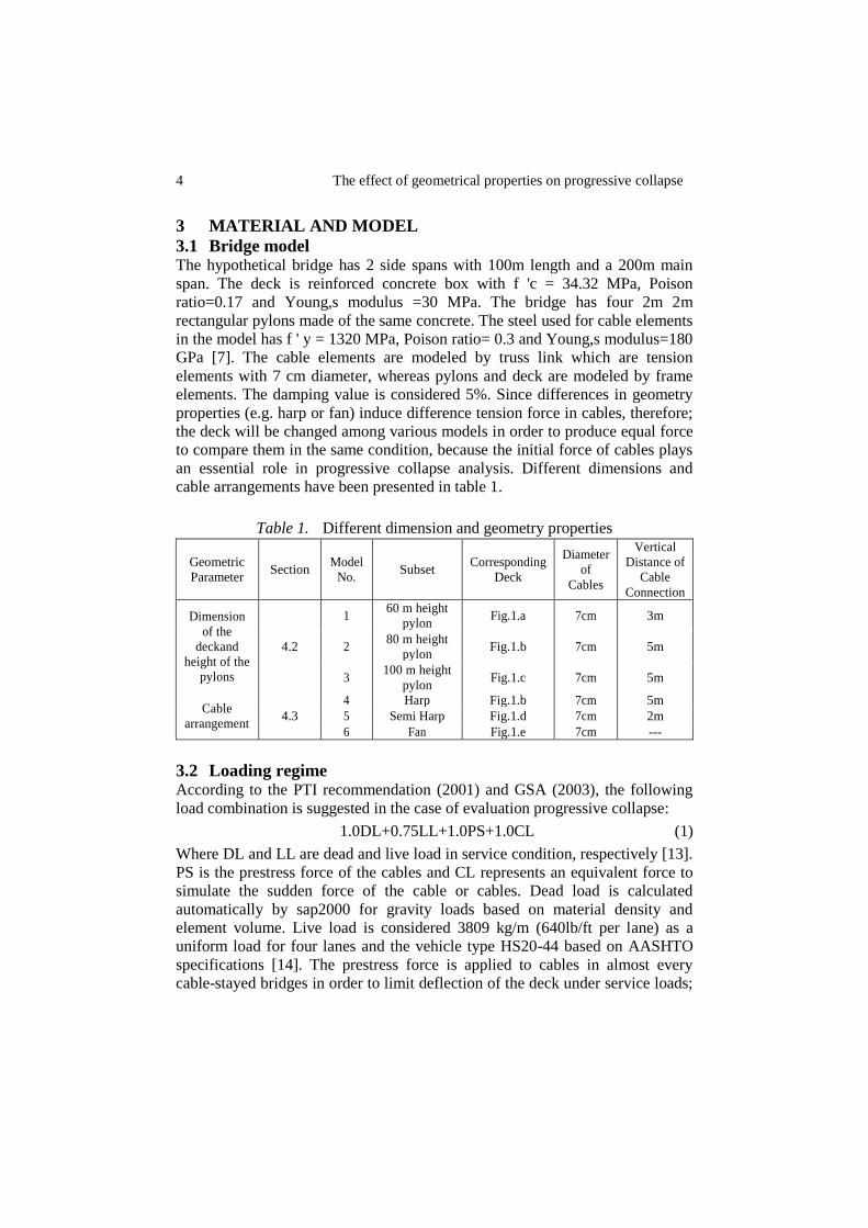
3.1 Bridge model The hypothetical bridge has 2 side spans with 100m length and a 200m main
span. The deck is reinforced concrete box with f 'c = 34.32 MPa, Poison
ratio=0.17 and Young,s modulus =30 MPa. The bridge has four 2m 2m
rectangular pylons made of the same concrete. The steel used for cable elements
in the model has f ' y = 1320 MPa, Poison ratio= 0.3 and Young,s modulus=180
GPa [7]. The cable elements are modeled by truss link which are tension
elements with 7 cm diameter, whereas pylons and deck are modeled by frame
elements. The damping value is considered 5%. Since differences in geometry
properties (e.g. harp or fan) induce difference tension force in cables, therefore;
the deck will be changed among various models in order to produce equal force
to compare them in the same condition, because the initial force of cables plays
an essential role in progressive collapse analysis. Different dimensions and
cable arrangements have been presented in table 1.
Table 1. Different dimension and geometry properties
Geometric
Parameter Section
Model
No. Subset
Corresponding
Deck
Diameter
of
Cables
Vertical
Distance of
Cable
Connection
Dimension
of the
deckand
height of the
pylons
4.2
1 60 m height
pylon Fig.1.a 7cm 3m
2 80 m height
pylon Fig.1.b 7cm 5m
3 100 m height
pylon Fig.1.c 7cm 5m
Cable
arrangement 4.3
4 Harp Fig.1.b 7cm 5m
5 Semi Harp Fig.1.d 7cm 2m
6 Fan Fig.1.e 7cm ---
3.2 Loading regime According to the PTI recommendation (2001) and GSA (2003), the following
load combination is suggested in the case of evaluation progressive collapse:
1.0DL+0.75LL+1.0PS+1.0CL (1)
Where DL and LL are dead and live load in service condition, respectively [13].
PS is the prestress force of the cables and CL represents an equivalent force to
simulate the sudden force of the cable or cables. Dead load is calculated
automatically by sap2000 for gravity loads based on material density and
element volume. Live load is considered 3809 kg/m (640lb/ft per lane) as a
uniform load for four lanes and the vehicle type HS20-44 based on AASHTO
specifications [14]. The prestress force is applied to cables in almost every
cable-stayed bridges in order to limit deflection of the deck under service loads;
Fathollahzadeh Et Al 5
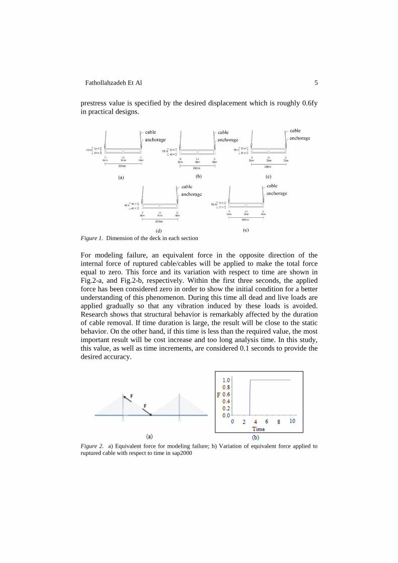
prestress value is specified by the desired displacement which is roughly 0.6fy
in practical designs.
Figure 1. Dimension of the deck in each section
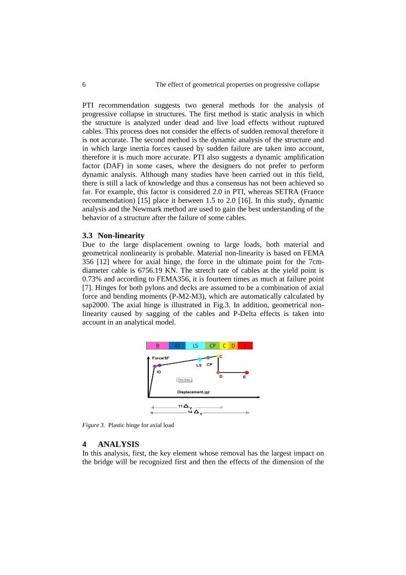
For modeling failure, an equivalent force in the opposite direction of the
internal force of ruptured cable/cables will be applied to make the total force
equal to zero. This force and its variation with respect to time are shown in
Fig.2-a, and Fig.2-b, respectively. Within the first three seconds, the applied
force has been considered zero in order to show the initial condition for a better
understanding of this phenomenon. During this time all dead and live loads are
applied gradually so that any vibration induced by these loads is avoided.
Research shows that structural behavior is remarkably affected by the duration
of cable removal. If time duration is large, the result will be close to the static
behavior. On the other hand, if this time is less than the required value, the most
important result will be cost increase and too long analysis time. In this study,
this value, as well as time increments, are considered 0.1 seconds to provide the
desired accuracy.
Figure 2. a) Equivalent force for modeling failure; b) Variation of equivalent force applied to
ruptured cable with respect to time in sap2000
6 The effect of geometrical properties on progressive collapse
PTI recommendation suggests two general methods for the analysis of
progressive collapse in structures. The first method is static analysis in which
the structure is analyzed under dead and live load effects without ruptured
cables. This process does not consider the effects of sudden removal therefore it
is not accurate. The second method is the dynamic analysis of the structure and
in which large inertia forces caused by sudden failure are taken into account,
therefore it is much more accurate. PTI also suggests a dynamic amplification
factor (DAF) in some cases, where the designers do not prefer to perform
dynamic analysis. Although many studies have been carried out in this field,
there is still a lack of knowledge and thus a consensus has not been achieved so
far. For example, this factor is considered 2.0 in PTI, whereas SETRA (France
recommendation) [15] place it between 1.5 to 2.0 [16]. In this study, dynamic
analysis and the Newmark method are used to gain the best understanding of the
behavior of a structure after the failure of some cables.
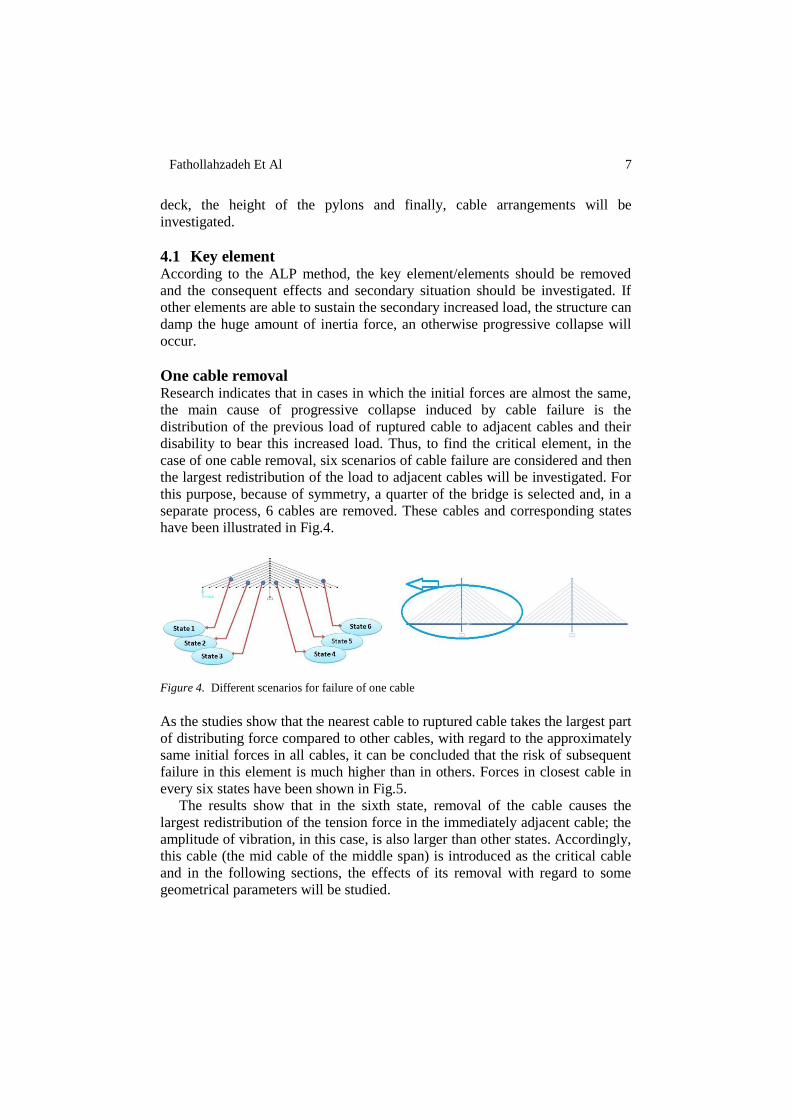
3.3 Non-linearity Due to the large displacement owning to large loads, both material and
geometrical nonlinearity is probable. Material non-linearity is based on FEMA
356 [12] where for axial hinge, the force in the ultimate point for the 7cm-
diameter cable is 6756.19 KN. The stretch rate of cables at the yield point is
0.73% and according to FEMA356, it is fourteen times as much at failure point
[7]. Hinges for both pylons and decks are assumed to be a combination of axial
force and bending moments (P-M2-M3), which are automatically calculated by
sap2000. The axial hinge is illustrated in Fig.3. In addition, geometrical non-
linearity caused by sagging of the cables and P-Delta effects is taken into
account in an analytical model.
Figure 3. Plastic hinge for axial load
4 ANALYSIS In this analysis, first, the key element whose removal has the largest impact on
the bridge will be recognized first and then the effects of the dimension of the
Fathollahzadeh Et Al 7
deck, the height of the pylons and finally, cable arrangements will be
investigated.
4.1 Key element According to the ALP method, the key element/elements should be removed
and the consequent effects and secondary situation should be investigated. If
other elements are able to sustain the secondary increased load, the structure can
damp the huge amount of inertia force, an otherwise progressive collapse will
occur.
One cable removal Research indicates that in cases in which the initial forces are almost the same,
the main cause of progressive collapse induced by cable failure is the
distribution of the previous load of ruptured cable to adjacent cables and their
disability to bear this increased load. Thus, to find the critical element, in the
case of one cable removal, six scenarios of cable failure are considered and then
the largest redistribution of the load to adjacent cables will be investigated. For
this purpose, because of symmetry, a quarter of the bridge is selected and, in a
separate process, 6 cables are removed. These cables and corresponding states
have been illustrated in Fig.4.
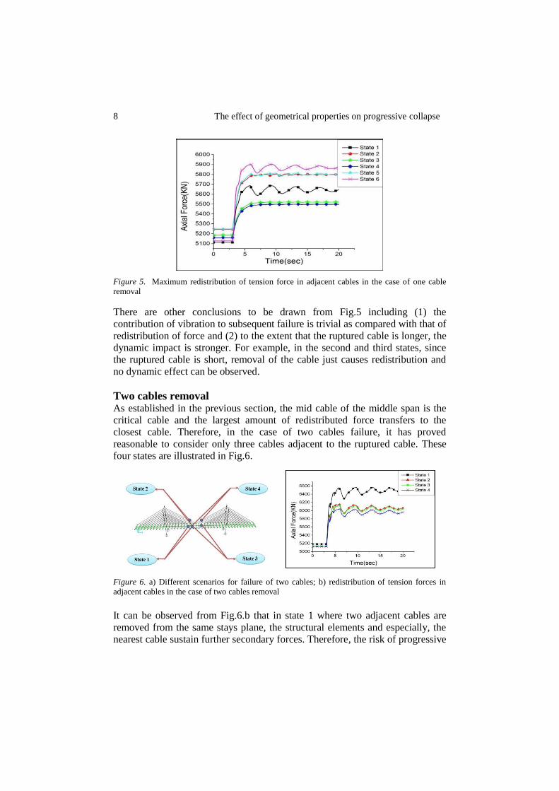
Figure 4. Different scenarios for failure of one cable
As the studies show that the nearest cable to ruptured cable takes the largest part
of distributing force compared to other cables, with regard to the approximately
same initial forces in all cables, it can be concluded that the risk of subsequent
failure in this element is much higher than in others. Forces in closest cable in
every six states have been shown in Fig.5.
The results show that in the sixth state, removal of the cable causes the
largest redistribution of the tension force in the immediately adjacent cable; the
amplitude of vibration, in this case, is also larger than other states. Accordingly,
this cable (the mid cable of the middle span) is introduced as the critical cable
and in the following sections, the effects of its removal with regard to some
geometrical parameters will be studied.
8 The effect of geometrical properties on progressive collapse
Figure 5. Maximum redistribution of tension force in adjacent cables in the case of one cable
removal
There are other conclusions to be drawn from Fig.5 including (1) the
contribution of vibration to subsequent failure is trivial as compared with that of
redistribution of force and (2) to the extent that the ruptured cable is longer, the
dynamic impact is stronger. For example, in the second and third states, since
the ruptured cable is short, removal of the cable just causes redistribution and
no dynamic effect can be observed.
Two cables removal As established in the previous section, the mid cable of the middle span is the
critical cable and the largest amount of redistributed force transfers to the
closest cable. Therefore, in the case of two cables failure, it has proved
reasonable to consider only three cables adjacent to the ruptured cable. These
four states are illustrated in Fig.6.
Figure 6. a) Different scenarios for failure of two cables; b) redistribution of tension forces in
adjacent cables in the case of two cables removal
It can be observed from Fig.6.b that in state 1 where two adjacent cables are
removed from the same stays plane, the structural elements and especially, the
nearest cable sustain further secondary forces. Therefore, the risk of progressive
Fathollahzadeh Et Al 9
collapse within the structure because of getting closer to the final force limit is
much higher. This secondary force is 1386.6, 1029.9, 995.4 and 914.3KN in the
states 1 to 4, respectively. This calculation can be performed for any number of
cables and it can be proved that for three and more cables removal, the same
results can be obtained.
4.2 The effect of dimension for structural elements
4.2.1 Dimension of the deck Among different models described in Table 1, dimensions of the deck and
height of the pylons are changed simultaneously. Therefore, if the geometry
properties have an impact on the response of structure against progressive
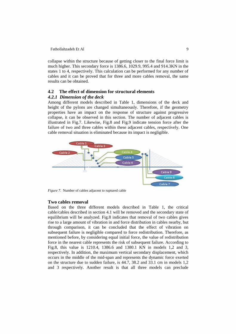
collapse, it can be observed in this section. The number of adjacent cables is
illustrated in Fig.7. Likewise, Fig.8 and Fig.9 indicate tension force after the
failure of two and three cables within these adjacent cables, respectively. One
cable removal situation is eliminated because its impact is negligible.
Figure 7. Number of cables adjacent to ruptured cable
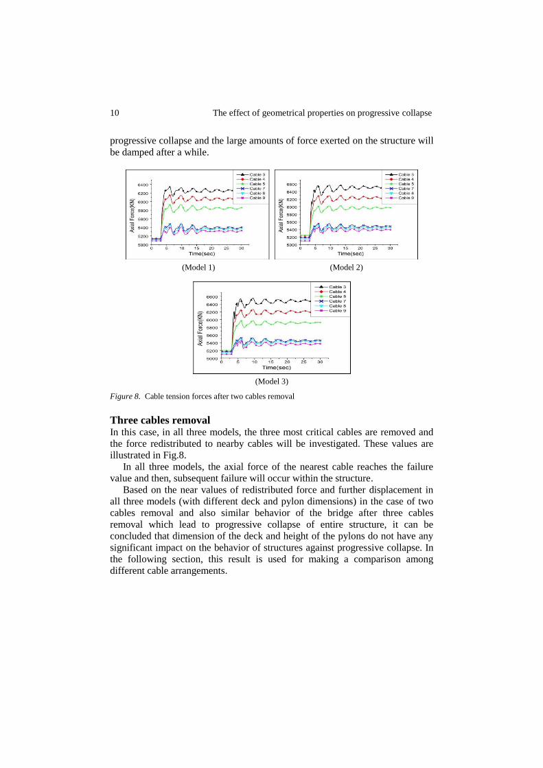
Two cables removal Based on the three different models described in Table 1, the critical
cable/cables described in section 4.1 will be removed and the secondary state of
equilibrium will be analyzed. Fig.8 indicates that removal of two cables gives
rise to a large amount of vibration in and force distribution in cables nearby, but
through comparison, it can be concluded that the effect of vibration on
subsequent failure is negligible compared to force redistribution. Therefore, as
mentioned before, by considering equal initial force, the value of redistribution
force in the nearest cable represents the risk of subsequent failure. According to
Fig.8, this value is 1210.4, 1386.6 and 1380.1 KN in models 1,2 and 3,
respectively. In addition, the maximum vertical secondary displacement, which
occurs in the middle of the mid-span and represents the dynamic force exerted
on the structure due to sudden failure, is 44.7, 38.2 and 33.1 cm in models 1,2
and 3 respectively. Another result is that all three models can preclude
10 The effect of geometrical properties on progressive collapse
progressive collapse and the large amounts of force exerted on the structure will
be damped after a while.
(Model 1) (Model 2)
(Model 3)
Figure 8. Cable tension forces after two cables removal
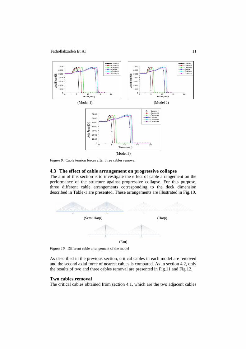
Three cables removal In this case, in all three models, the three most critical cables are removed and
the force redistributed to nearby cables will be investigated. These values are
illustrated in Fig.8.
In all three models, the axial force of the nearest cable reaches the failure
value and then, subsequent failure will occur within the structure.
Based on the near values of redistributed force and further displacement in
all three models (with different deck and pylon dimensions) in the case of two
cables removal and also similar behavior of the bridge after three cables
removal which lead to progressive collapse of entire structure, it can be
concluded that dimension of the deck and height of the pylons do not have any
significant impact on the behavior of structures against progressive collapse. In
the following section, this result is used for making a comparison among
different cable arrangements.
Fathollahzadeh Et Al 11
(Model 1) (Model 2)
(Model 3)
Figure 9. Cable tension forces after three cables removal
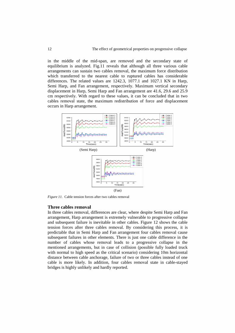
4.3 The effect of cable arrangement on progressive collapse The aim of this section is to investigate the effect of cable arrangement on the
performance of the structure against progressive collapse. For this purpose,
three different cable arrangements corresponding to the deck dimension
described in Table-1 are presented. These arrangements are illustrated in Fig.10.
(Semi Harp) (Harp)
(Fan)
Figure 10. Different cable arrangement of the model
As described in the previous section, critical cables in each model are removed
and the second axial force of nearest cables is compared. As in section 4.2, only
the results of two and three cables removal are presented in Fig.11 and Fig.12.
Two cables removal The critical cables obtained from section 4.1, which are the two adjacent cables
12 The effect of geometrical properties on progressive collapse
in the middle of the mid-span, are removed and the secondary state of
equilibrium is analyzed. Fig.11 reveals that although all three various cable
arrangements can sustain two cables removal, the maximum force distribution
which transferred to the nearest cable to ruptured cables has considerable
differences. The related values are 1242.3, 1077.1 and 1027.1 KN in Harp,
Semi Harp, and Fan arrangement, respectively. Maximum vertical secondary
displacement in Harp, Semi Harp and Fan arrangement are 41.6, 29.6 and 25.9
cm respectively. With regard to these values, it can be concluded that in two
cables removal state, the maximum redistribution of force and displacement
occurs in Harp arrangement.
(Semi Harp) (Harp)
(Fan)
Figure 11. Cable tension forces after two cables removal
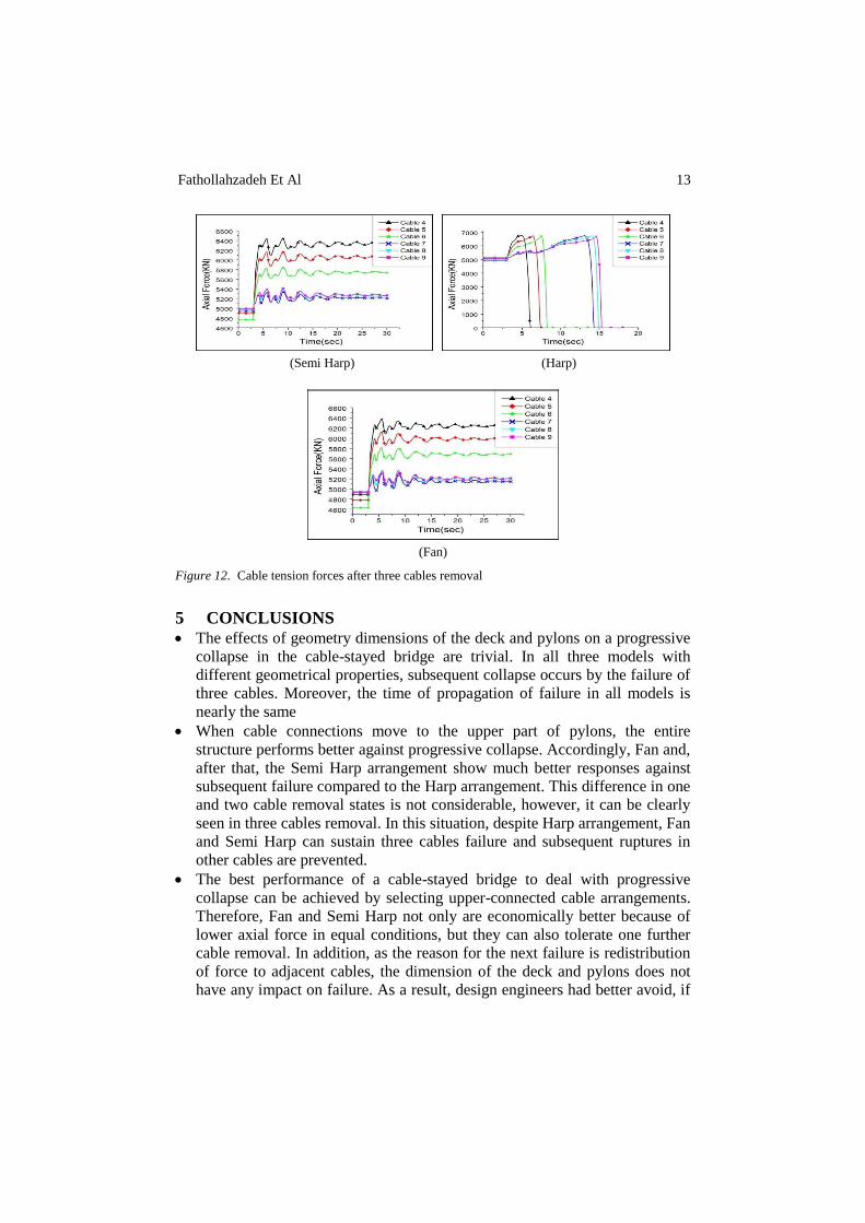
Three cables removal In three cables removal, differences are clear, where despite Semi Harp and Fan
arrangement, Harp arrangement is extremely vulnerable to progressive collapse
and subsequent failure is inevitable in other cables. Figure 12 shows the cable
tension forces after three cables removal. By considering this process, it is
predictable that in Semi Harp and Fan arrangement four cables removal cause
subsequent failures in other elements. There is just one cable difference in the
number of cables whose removal leads to a progressive collapse in the
mentioned arrangements, but in case of collision (possible fully loaded truck
with normal to high speed as the critical scenario) considering 10m horizontal
distance between cable anchorage, failure of two or three cables instead of one
cable is more likely. In addition, four cables removal state in cable-stayed
bridges is highly unlikely and hardly reported.
Fathollahzadeh Et Al 13
(Semi Harp) (Harp)
(Fan)
Figure 12. Cable tension forces after three cables removal
5 CONCLUSIONS
The effects of geometry dimensions of the deck and pylons on a progressive
collapse in the cable-stayed bridge are trivial. In all three models with
different geometrical properties, subsequent collapse occurs by the failure of
three cables. Moreover, the time of propagation of failure in all models is
nearly the same
When cable connections move to the upper part of pylons, the entire
structure performs better against progressive collapse. Accordingly, Fan and,
after that, the Semi Harp arrangement show much better responses against
subsequent failure compared to the Harp arrangement. This difference in one
and two cable removal states is not considerable, however, it can be clearly
seen in three cables removal. In this situation, despite Harp arrangement, Fan
and Semi Harp can sustain three cables failure and subsequent ruptures in
other cables are prevented.
The best performance of a cable-stayed bridge to deal with progressive
collapse can be achieved by selecting upper-connected cable arrangements.
Therefore, Fan and Semi Harp not only are economically better because of
lower axial force in equal conditions, but they can also tolerate one further
cable removal. In addition, as the reason for the next failure is redistribution
of force to adjacent cables, the dimension of the deck and pylons does not
have any impact on failure. As a result, design engineers had better avoid, if
14 The effect of geometrical properties on progressive collapse
possible, parallel cable arrangements and turn to Semi Harp or Fan
arrangements.
REFERENCES [1] Institute, S.E, Minimum Design Loads for Buildings and other Structures, Vol. 7, American
Society of Civil Engineering, 2006. [2] Ellingwood, B.R, Leyendecker, E, “Approaches for design against progressive collapse”,
Journal of the Structural Division, Vol. 104, No. 3, pp. 413-423, 1978.
[3] Starossek, U, “Typology of progressive collapse”, Engineering Structures, Vol. 29, No. 9, pp.
2302-2307, 2007.
[4] Starossek, U, “Progressive collapse study of a multi-span bridge”, Structural Engineering
International, Vol. 9, No. 2, pp. 121-125, 1999.
[5] Astaneh-Asl, A, “Progressive collapse of steel truss bridges, the case of I-35W collapse”,
Proc. 7th Intl. Conference on Steel Bridges, Guimarăes, Portugal, 2008.
[6] Hao, S, “I-35W bridge collapse”, Journal of Bridge Engineering, Vol. 15, No. 5, pp. 608-
614, 2009.
[7] Cai, J.g, et al, “Comparison of various procedures for progressive collapse analysis of cable-
stayed bridges”, Journal of Zhejiang University SCIENCE A, Vol. 13, No. 5, pp. 323-334,
2012.
[8] Fatollahzadeh, A, M, Naghipour, G. Abdollahzadeh, “Analysis of progressive collapse in
cable-stayed bridges due to cable failure during earthquake”, International Journal of Bridge
Engineering, Vol. 4, No. 2, pp. 63-72, 2016.
[9] Kim, S, Y.J, Kang, “Structural behaviour of cable-stayed bridges after cable failure”,
Structural Engineering and Mechanics, Vol. 59, No. 6, pp. 1095-1120, 2016.
[10] Ruiz-Teran, A, Aparicio, A, “Dynamic amplification factors in cable-stayed structures”,
Journal of sound and vibration, Vol. 300, No. 1-2, pp. 197-216, 2007.
[11] Aoki, Y, et al, “Sensitivity analysis for steel deck of a cable-stayed bridge subjected to blast
loadings”, Proc. 23rd Australasian Conference on the Mechanics of Structures and Materials, Byron Bay, Australia, 2014.
[12] Ruiz-Teran, A, Aparicio, A, “Response of under-deck cable-stayed bridges to the accidental
breakage of stay cables”, Engineering Structures, Vol. 31, No. 7, pp. 1425-1434, 2009.
[13] Specification, P.G., Recommendations for stay cable design, testing and installation. Post-
Tensioning Institute Committee on Cable-Stayed Bridges, 2001.
[14] AASHTO, L., AASHTO LRFD bridge design specifications Transportation (Amst).
American Association of State Highway and Transportation Officials, Inc.: Washington, DC,
2007.
[15] Haubans, S., Recommandations de la Commission Interministérielle de la Précontrainte.
Service d’Etudes Techniques des Routes et Autoroutes, France, 2001.
[16] Mozos, C, Aparicio, A, “Parametric study on the dynamic response of cable stayed bridges to
the sudden failure of a stay, Part I: Bending moment acting on the deck”, Engineering
Structures, Vol. 32, No. 10, pp. 3288-3300, 2010.