Embed Size (px)
Citation preview
The Eins3D project – Instantaneous UAV-Based 3D Mapping for Search
and Rescue Applications
Helge A. Lauterbach1, C. Bertram Koch2, Robin Hess2, Daniel Eck2,
Klaus Schilling1,2 and Andreas Nuchter1,2
Abstract— The overview of a situation in a search andrescue disaster is the key aspect of an effective assistance. Inthe recent years the utilization of multicopter with variousphotogrammetry systems is an upcoming trend and an openfield of research. This paper discusses the technical aspects of anautomated integral system that will support rescuers during thestrategic mission planning and will give situational awarenessby instantaneous 3D mapping. The approach combines sensorsincluding a 3D Laserscanner, a thermal camera and an attitudesystem as a payload unit on an Multicopter. The continuousdata fusion and the down link are providing an instant 3Denvironment map that is continuously revised and updated.
I. INTRODUCTION
The classification of a situation in Urban Search and
Rescue (USaR) missions is often a challenging task due its
complexity. The general view of a scenario is the key aspect
in strategic mission planning. It is necessary to priories
urgencies in a situation of danger. Staying on top of things in
a constantly changing situation requires also regular scenario
monitoring. Nowadays the assessment of disaster situations
is done by visual inspection through rescuers, a dangerous
and time costly strategy. This process is aided with surveying
by aerial photo- and thermography taken from a helicopter.
The search and rescue of victims is often a trade off between
the urgency and the danger for rescuers. New technologies
in this field should reduce risks and facilitate missions.
Recently unmanned aerial vehicles (UAV) with optical
and thermal cameras are introduced for this purpose. Such
systems are more flexible and provide a higher level of
availability. However, the data acquisition during a manual
flight is a complex task and the evaluation, especially of
video footage, is quite time demanding. Optical inspections
done by such an UAV does not provide spatial information
of the environment.
The project Eins3D (Luftbasierte Einsatzumge-
bungsaufklarung in 3D) is aimed at the development
of a single drone 3D mapping solution. The intended
automated approach expedites the operation, the data
acquisition and the evaluation process of USaR missions.
During an autonomous flight the operational area is scanned
by the optical and laser sensors of the payload. The acquired
sensor data is fused to a 3D map in an instant fashion.
1 Department of Informatics VII — Robotics and Telem-atics, Julius-Maximilians-University Wurzburg, Wurzburg,Germany {helge.lauterbach|andreas.nuechter}@uni-wuerzburg.de
2 Center for Telematics, 97074 Wurzburg, Ger-many, {b.koch|d.eck|r.hess|k.schilling}@telematik-zentrum.de
Real-time mapping enables regular situation update of 3D
maps. This is beneficial especially in USarR applications
for example to improve strategic planning for coordination,
enhance situation awareness for firefighters and rescue
workers and to support structural inspections.
II. RELATED WORK
Recently the use of UAVs in disaster response is an
active field of research. Scherer et al. propose a modular
multirobot system supporting a heterogeneous set of UAVs
and camera sensors [1]. As a search and rescue application
they demonstrate the detection of victims. In [2] a small fully
autonomous UAV is presented also used for victim detection.
However both approaches do not focus on mapping.
UAV based approaches to 3D mapping often rely on struc-
ture from motion techniques. They usually do not provide 3D
maps immediately, as dense mapping has high computational
requirements [3]. This time consuming step often takes
several hours to complete. Photogrammetric approaches
are therefore mostly applied to large scale scenarios, e.g.
earthquakes [4]. In the TRADR (Long-Term Human-Robot
Teaming for Disaster Response) project 3D point clouds are
generated from camera images and combined with 3D point
clouds from laser scanners carried by ground robots [5].
Within the project Mapping on Demand [6] a 3D laser
scanner is used to build a local map of the environment
for navigation tasks. However the actual mapping is then
achieved by structure from motion.
In contrast to those approaches the solution developed in
Eins3D focuses on a single UAV system, applicable for small
to medium size sorties. By relying on a Light Detection and
Range (LiDAR) sensor the environment is instantaneously
available.
III. SYSTEM OVERVIEW
The system, presented in this paper, is functionally clas-
sified in ground segment, aerial segment and payload. A
sketch of the elements and the interactions are shown in
figure 2. The ground segment is a mobile control station
implemented in a fire fighter command vehicle as shown
in figure 3. It communicates with the aerial segment via
a custom build radio interface. The aerial segment is a
medium-sized multicopter. With the frame arms of the copter
fold up, it is loaded in the fire fighter command vehicle.
Figure 1 shows a picture of the payload, the major element
of our system. This sensor unit is an integral system specif-
ically developed for the environment mapping application

1
2
3
Fig. 1: The sensor unit featuring a Xsens Mti-G 700 (1) IMU,
a Velodyne VLP16 Lite (2) laser scanner and an Optris PI
640 LW (3) thermal camera.
and for search-and-rescue missions. Its main sensors are
a 3D LiDAR, a thermal camera and an attitude sensor.
Additionally a RGB camera is mounted. Sensor data logging
and flight control is done by a single-board computer running
Robot Operating System (ROS). The final sensor unit will be
equipped with a wireless radio control and communication
unit capable of streaming sensor data to the ground station.
The following section gives an overview of the system and
discusses the key features of the components and the sensors.
A. Ground segment
The main part of the ground segment is a system control
station. It is used for mission planning, flight monitoring
and data evaluation. The concept of a German standard fire
fighter command vehicle (ELW 1 – DIN14507-2) is refined,
for the upcoming utilization of UAVs in search and rescue
missions. The ground segment is implemented in this vehicle.
There are two work areas with a standard desktop computer,
a network connected to the Internet and a radio control
system.
B. Radio system
A pilot is compulsory due to aviation restrictions during
scan-flights. Task of the pilot is to monitor an ongoing
mission and to take over control in case of an unexpected
situation. Therefore two independent radio systems are im-
plemented.
Firstly a master system, commonly used in the radio
control (rc) community, enables the pilot to take over control,
to interrupt an ongoing mission and to continue in a manual
flight mode.
Secondly a high bandwidth, low energy radio system
is under development specifically for the project purpose.
The up-link embrace control and mission commands, the
down-link UAV house keeping information and sensor data.
The required throughput of the down-link is several orders
of magnitudes greater than the up-link. The reason is the
high data rate of the sensors used for mapping. First range
experiments of the transceiver system showed a throughput
rate of 326.5 Mbits at a distance of 300 m.
C. Aerial segment
The aerial segment is a medium size off-the-shelf profes-
sional grade multicopter, namely a DJI S1000+. It features
a octorotor configuration, a frame weight of 4.4 kg and a
maximum takeoff weight of 11 kg. The UAV provides a
sufficient lifting capability for the sensor unit. This unit is
fitted at the gimbal mount of the UAV. A picture of the
configuration is presented in figure 4. The entire system has
a takeoff weight of 9.5 kg is powered by a 6 S battery with
18 Ah. Under optimal conditions it is capable of a maximum
flight time of 15 min.
The UAV is controlled by the A3 Pro of DJI, a flight con-
trol unit (FCU) for multirotor aerial platforms. This control
system fuses three sets of redundant sensors, each of them
including an IMU, a barometer and a GPS sensor. Therefore
it gains failure safety and a higher accuracy through internal
sensor fusion. The FCU is linked via a serial connection
and an API interface to an onboard computer. The API
is a communication wrapper providing attitude and status
information and a UAV flight control interface. The master
radio controller, discussed previously, is directly connected
via S.Bus.
D. Sensors
The core part of the system presented is the sensor unit,
as depicted in figure 1. The main sensor of our mapping
system is a Velodyne Puck VLP16 Lite laser scanner. With its
low weight of 830 g and typical power consumption of 8 W,
the sensor is appropriate for aerial mapping. It provides full
360 ◦ scans at a frequency of 10 Hz with a maximum range
of 100 m. The vertical FoV of 30 ◦ is sparsely covered by 16
line laser scans with an angular resolution of 2 ◦ vertically
and 0.2 ◦ horizontally.
As a second sensor the system features a Optris PI 640LW
thermal camera to enrich the map with registered temperature
information. In order to maximize the overlap with the laser
scanner a wide angle lens with a FoV of 90 ◦ x 64 ◦ is
used. Thermal images are captured at VGA resolution with a
frequency of 10 Hz. Additional sensors are mountable on the
system. Temporarly a Logitech Brio rgb camera is tested to
enrich the optical spectrum. The rolling shutter of the system
and the high frequency vibrations of the UAV resulted an a
non-satisfying video output.
For pose estimation we primarily we rely on the attitude
sensors of the FCU. However we mounted an additional
Xsens Mti-G 700 to enable the usage of the sensor unit
independent of the UAV. This sensor fuses IMU and GPS
data to increase the longterm stability of the orientation
measurements and provides position data with 400 Hz.
An important design decision is the disposal and orienta-
tion of the mounted sensors. Considering the narrow vertical
FoV of the Velodyne laser scanner, it needs to be inclined
to enable measurements on the ground. Depending on the
flight altitude, the effectively horizontal FoV is reduced to
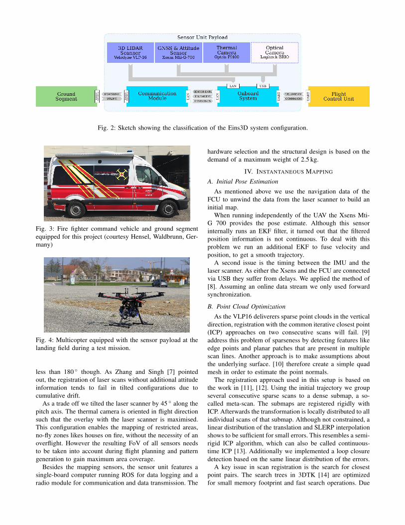
Fig. 2: Sketch showing the classification of the Eins3D system configuration.
Fig. 3: Fire fighter command vehicle and ground segment
equipped for this project (courtesy Hensel, Waldbrunn, Ger-
many)
Fig. 4: Multicopter equipped with the sensor payload at the
landing field during a test mission.
less than 180 ◦ though. As Zhang and Singh [7] pointed
out, the registration of laser scans without additional attitude
information tends to fail in tilted configurations due to
cumulative drift.
As a trade off we tilted the laser scanner by 45 ◦ along the
pitch axis. The thermal camera is oriented in flight direction
such that the overlay with the laser scanner is maximised.
This configuration enables the mapping of restricted areas,
no-fly zones likes houses on fire, without the necessity of an
overflight. However the resulting FoV of all sensors needs
to be taken into account during flight planning and pattern
generation to gain maximum area coverage.
Besides the mapping sensors, the sensor unit features a
single-board computer running ROS for data logging and a
radio module for communication and data transmission. The
hardware selection and the structural design is based on the
demand of a maximum weight of 2.5 kg.
IV. INSTANTANEOUS MAPPING
A. Initial Pose Estimation
As mentioned above we use the navigation data of the
FCU to unwind the data from the laser scanner to build an
initial map.
When running independently of the UAV the Xsens Mti-
G 700 provides the pose estimate. Although this sensor
internally runs an EKF filter, it turned out that the filtered
position information is not continuous. To deal with this
problem we run an additional EKF to fuse velocity and
position, to get a smooth trajectory.
A second issue is the timing between the IMU and the
laser scanner. As either the Xsens and the FCU are connected
via USB they suffer from delays. We applied the method of
[8]. Assuming an online data stream we only used forward
synchronization.
B. Point Cloud Optimization
As the VLP16 deliverers sparse point clouds in the vertical
direction, registration with the common iterative closest point
(ICP) approaches on two consecutive scans will fail. [9]
address this problem of sparseness by detecting features like
edge points and planar patches that are present in multiple
scan lines. Another approach is to make assumptions about
the underlying surface. [10] therefore create a simple quad
mesh in order to estimate the point normals.
The registration approach used in this setup is based on
the work in [11], [12]. Using the initial trajectory we group
several consecutive sparse scans to a dense submap, a so-
called meta-scan. The submaps are registered rigidly with
ICP. Afterwards the transformation is locally distributed to all
individual scans of that submap. Although not constrained, a
linear distribution of the translation and SLERP interpolation
shows to be sufficient for small errors. This resembles a semi-
rigid ICP algorithm, which can also be called continuous-
time ICP [13]. Additionally we implemented a loop closure
detection based on the same linear distribution of the errors.
A key issue in scan registration is the search for closest
point pairs. The search trees in 3DTK [14] are optimized
for small memory footprint and fast search operations. Due
to its compact representation in memory they do not allow
for dynamic extension. Thus, in sequential registration the
entire map needs to be rebuilt for each inserted submap. The
registration process is speed up by maintaining and querying
several search trees of already merged submaps in parallel,
thus reducing the frequency of map rebuilding. To further
speed up the process we use a keyframe approach based on
the distance moved since the last keyframe. Especially when
flying at low speed, the registration of all acquired laser scans
does add only little information to the map anyways.
After the optimization the improved trajectory is used to
geolocate the final point cloud. The optimized trajectory is
rigidly aligned the original GNSS measurements, considering
correspondences from time stamps.
C. Thermal Mapping
As mentioned before, thermal information is used by
firefighters to detect either temperature hot spots that may
indicate hidden fires or to detect humans and animals in
search and rescue scenarios.
1) Calibration: For projection of thermal data to the point
cloud a precise transformation between camera and laser
scanner needs to be known. Previously Borrmann et al. [15]
proposed a method to estimate the extrinsic calibration
between a thermal camera and a surveyor grade 3D laser
scanner. A board with clearly defined heat sources, e.g.
small lightbulbs, that are positioned in a grid, similar to
corners of a chessboard is used as calibration target. After
applying upper and lower thresholds the pattern is extracted
from the thermal images. The board is then detected in
the laser scans by finding the most prominent plane with
RANSAC and registration of a point cloud representation of
the board. The extrinsic calibration is then estimated from
N images and scans of the calibration pattern with M point
correspondences by minimizing the reprojection error
N∑
i
M∑
j
∥
∥pi,j − proj(K,D,RCL , t
CL ,Pi,j)
∥
∥
2
(1)
where proj is the projection of the point P from the laser
scanner coordinate system L on the image plane with in-
trinsic matrix K, distortion parameters D and the estimated
rotation matrix R and translation vector t from L into the
camera coordinate system C. This approach works well
for dense point clouds. However in case of sparse point
clouds e.g. from a Velodyne VLP16 as used in our setup,
a rectangular flat board is problematic since the pose of the
board cannot be determined unambiguously due to the coarse
resolution in vertical direction. Therefore we mounted the
lightbulb pattern on a cuboid structure which enables distinct
pose estimation.
Timing is crucial in a mobile mapping context. We ex-
tended the approach to enable the estimation of the sensor
clock offset. In contrast to [15] we collect data while moving
the sensor unit in front of the target during data acquisition.
We then compute the trajectory of the laser scanner by
sequential registration where the origin of the calibration
target defines the global coordinate system. For a thermal
image with successfully detected pattern we compute the
interpolated corresponding scanner pose from the previously
computed trajectory and establish the correspondences. The
extrinsic calibration is then computed by minimizing Eq. 1.
The calibration of the clock offset is done by rerunning the
calibration with binary search in a predefined interval of
clock offsets.
2) Data Projection: During flight data is acquired for all
sensors simultaneously. The determined extrinsic calibration
is used to directly assign temperature values to points.
Suppose a scan was acquired at time i and the image to
be projected on the point cloud at time j. Using forward
projection proj from Eq. 1 the laser scan is first transformed
from its local coordinate system L at time i to the global
coordinate system W and then to the camera coordinate
system C at j:
pC,j = TCLT
LW,jT
WL,ipL,i (2)
= TCLT
L,jL,ipi (3)
The temperature values are assigned by projection to the
image plane, before back transforming the scan to L at i.
Although not restricted to, we select the closest image in
time for projection.
Considering the field of view of laser scanner and thermal
camera, with this forward projection approach not all points
of a laser scan are assigned with a temperature value. This
produces a This issue could be resolved by backprojecting
the images on the final global point cloud. However this
computational more complex as raycasting is needed for
each pixel of an image. We decided for the fast forward
projection. We instead address this issue in a postprocessing
step after the trajectory optimization. Therefore we again
exploit our octree structure by assigning the median of all
valid temperature measurements of a voxel to the points of
that particular voxel.
V. RESULTS
We tested our sensor unit in a flight at the robotics hall of
the university of Wurzburg. The UAV was flown manually
in several loops alongside the building. From 137 s of flight
the laser scans were extracted resulting in 285 keyframes.
Figure 5 on the left visualizes the point cloud after the
initial trajectory estimation. The point clouds are colored
by reflectance values. The red line resembles the flown
trajectory.
Visual inspection of the 3D model reveals that the most
prominent errors appear in the up-axis. This is caused by the
height estimation from the barometer and non ideal GNSS
conditions. This is noticeable on the roof of the robotics hall
(bottom left). The uncertainty in GNSS measurements also
affects the heading estimation, as seen on the building in the
top left corner of the figure.
After applying 4 iterations of our continuous-time ICP
approach, the initial one with loop closure, the errors are
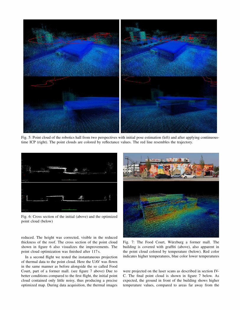
Fig. 5: Point cloud of the robotics hall from two perspectives with initial pose estimation (left) and after applying continuous-
time ICP (right). The point clouds are colored by reflectance values. The red line resembles the trajectory.
Fig. 6: Cross section of the initial (above) and the optimized
point cloud (below)
reduced. The height was corrected, visible in the reduced
thickness of the roof. The cross section of the point cloud
shown in figure 6 also visualizes the improvements. The
point cloud optimization was finished after 117 s.
In a second flight we tested the instantaneous projection
of thermal data to the point cloud. Here the UAV was flown
in the same manner as before alongside the so called Food
Court, part of a former mall. (see figure 7 above) Due to
better conditions compared to the first flight, the initial point
cloud contained only little noisy, thus producing a precise
optimized map. During data acquisition, the thermal images
Fig. 7: The Food Court, Wurzburg a former mall. The
building is covered with graffiti (above), also apparent in
the point cloud colored by temperature (below). Red color
indicates higher temperatures, blue color lower temperatures
were projected on the laser scans as described in section IV-
C. The final point cloud is shown in figure 7 below. As
expected, the ground in front of the building shows higher
temperature values, compared to areas far away from the
building, due to reflection of sunlight.
VI. CONCLUSIONS AND FUTURE WORK
In this paper we presented our approach of an accessible
application-orientated solution of a 3D mapping tool for
USaR missions. The overall system is presented and the
mayor aspects are discussed. To number among the hardware
of the integral system, the sensor data processing pipeline,
the automated trajectory planing and flight execution. It
presents the current results at an intermediate state in the
life span of this research project.
Subjects of future work are the elaboration and field tests
of the automated path planning.
Furthermore we plan to work on a monitoring system
of the mapped environment to aid the situational awareness
during a mission. This also includes the enhancement of the
model with additional information from semantic analysis of
point cloud and thermal data.
The presentation of the 3D map in a demand oriented way,
will be part of the mission control software.
A key part of the overall system that needs to be done, is
the integration and evaluation of the high bandwidth radio
system, to enable instantaneous mapping while the UAV is
still airborne.
Further milestones are performance test in association with
firefighters under simulated operational conditions.
ACKNOWLEDGMENTS
This work was partially funded by the project Eins3D
(FZK 13N14183, FZK 13N14182) from the Federal Ministry
of Education and Research. We thank our project part-
ners firm Hensel Fahrzeugbau GmbH in Waldbrunn, SLK
GmbH in Saarbrucken and the Bavarian Firefighter School
in Wurzburg.
REFERENCES
[1] J. Scherer, S. Yahyanejad, S. Hayat, E. Yanmaz, T. Andre, A. Khan,V. Vukadinovic, C. Bettstetter, H. Hellwagner, and B. Rinner, “Anautonomous multi-uav system for search and rescue,” in Proceedingsof the First Workshop on Micro Aerial Vehicle Networks, Systems, and
Applications for Civilian Use. ACM, 2015, pp. 33–38.
[2] T. Tomic, K. Schmid, P. Lutz, A. Domel, M. Kassecker, E. Mair,I. L. Grixa, F. Ruess, M. Suppa, and D. Burschka, “Toward a fullyautonomous uav: Research platform for indoor and outdoor urbansearch and rescue,” IEEE robotics & automation magazine, vol. 19,no. 3, pp. 46–56, 2012.
[3] A. Martell, H. A. Lauterbach, K. Schilling, and A. Nuchter, “Bench-marking Structure from Motion Algorithms of Urban Environmentswith Applications to Reconnaissance in Search and Rescue Scenarios,”in Proceedings of the 16th IEEE International Symposium on Safety,
Security, and Rescue Robotics (SSRR ’18), Philadelphia, PA, USA,August 2018, pp. 1–7.
[4] S. Verykokou, A. Doulamis, G. Athanasiou, C. Ioannidis, andA. Amditis, “Uav-based 3d modelling of disaster scenes for urbansearch and rescue,” in 2016 IEEE International Conference on Imaging
Systems and Techniques (IST). IEEE, 2016, pp. 106–111.
[5] A. Gawel, R. Dube, H. Surmann, J. Nieto, R. Siegwart, and C. Cadena,“3d registration of aerial and ground robots for disaster response: Anevaluation of features, descriptors, and transformation estimation,” inProceedings of the IEEE International Symposium on Safety, Securityand Rescue Robotics (SSRR ’17), Shanghai, China, September 2017,pp. 27–34.
[6] L. Klingbeil, M. Nieuwenhuisen, J. Schneider, C. Eling, D. Droeschel,D. Holz, T. Labe, W. Forstner, S. Behnke, and H. Kuhlmann, “Towardsautonomous navigation of an uav-based mobile mapping system,” inProc. of Int. Conf. on Machine Control & Guidance (MCG), 2014.
[7] J. Zhang and S. Singh, “Aerial and ground-based collaborative map-ping: an experimental study,” in Field and Service Robotics. Springer,2018, pp. 397–412.
[8] E. Olson, “A passive solution to the sensor synchronization problem,”in Intelligent Robots and Systems (IROS), 2010 IEEE/RSJ Interna-tional Conference on. IEEE, 2010, pp. 1059–1064.
[9] J. Zhang and S. Singh, “Loam: Lidar odometry and mapping in real-time.” in Robotics: Science and Systems, vol. 2, 2014.
[10] D. Holz and S. Behnke, “Registration of non-uniform density 3dlaser scans for mapping with micro aerial vehicles,” Robotics and
Autonomous Systems, vol. 74, pp. 318–330, 2015.[11] J. Elseberg, D. Borrmann, and A. Nuchter, “Algorithmic solutions for
computing accurate maximum likelihood 3D point clouds from mobilelaser scanning platforms,” Remote Sensing, vol. 5, no. 11, pp. 5871–5906, November 2013.
[12] H. A. Lauterbach and A. Nuchter, “Preliminary Results on Instanta-neous UAV-Based 3D Mapping for Rescue Applications,” in Proceed-
ings of the 16th IEEE International Symposium on Safety, Security, and
Rescue Robotics (SSRR ’18), Philadelphia, PA, USA, August 2018, pp.1–2.
[13] A. Nuchter, M. Bleier, J. Schauer, and P. Janotta, “Improving Google’sCartographer 3D Mapping by Continuous-Time SLAM,” in Proceed-
ings of the 7th ISPRS International Workshop 3D-ARCH 2017: ”3DVirtual Reconstruction and Visualization of Complex Architectures”,ser. ISPRS Archives Photogrammetry and Remote Senssing SpatialInf. Sci., Volume XLII/W3, Nafplio, Greece, March 2017, pp. 543–549.
[14] J. Elseberg, S. Magnenat, R. Siegwart, and A. Nuchter, “Comparisonon nearest-neigbour-search strategies and implementations for efficientshape registration,” Journal of Software Engineering for Robotics(JOSER), vol. 3, no. 1, pp. 2–12, 2012.
[15] D. Borrmann, H. Afzal, J. Elseberg, and A. Nuchter, “MutualCalibration for 3D Thermal Mapping,” in Proceedings of
the 10th International IFAC Symposium on Robot Control(SYROCO ’12), vol. 10, Dubrovnik, Croatia, September2012. [Online]. Available: https://robotik.informatik.uni-wuerzburg.de/telematics/download/syroco2012 2.pdf