Embed Size (px)
Citation preview
The Electrical Interface
USB Complete 505
19
The Electrical InterfaceAll of the protocols and program code in the world are no use if the signalsdon’t make it down the cable in good shape. The electrical interface plays animportant part in making USB a reliable way to transfer information.
From a practical point of view, if you’re using compliant cables and compo-nents, you don’t need to know much about the electrical interface. But ifyou’re designing USB transceivers or cables, printed-circuit boards withUSB interfaces, or a protocol analyzer that must unobtrusively monitor thebus, you do need to understand the electrical interface and how it affects thecomponents in your project.
This chapter presents the essentials about the electrical interface of theUSB’s drivers and receivers and details about the cables that carry the sig-nals.
Chapter 19
506 USB Complete
Transceivers and SignalsThe electrical properties of the signals on a USB cable vary depending onthe speed of the cable segment. Low-, full-, and high-speed signaling eachhave a different edge rate, which is a measure of the rise and fall times of thevoltages on the lines and thus the amount of time required for an output toswitch. The transceivers and supporting circuits that produce and detect thebus signals also vary depending on speed.
At any speed, the components that connect to a USB cable must be able towithstand the shorting of any line to any other line or the cable shield with-out component damage.
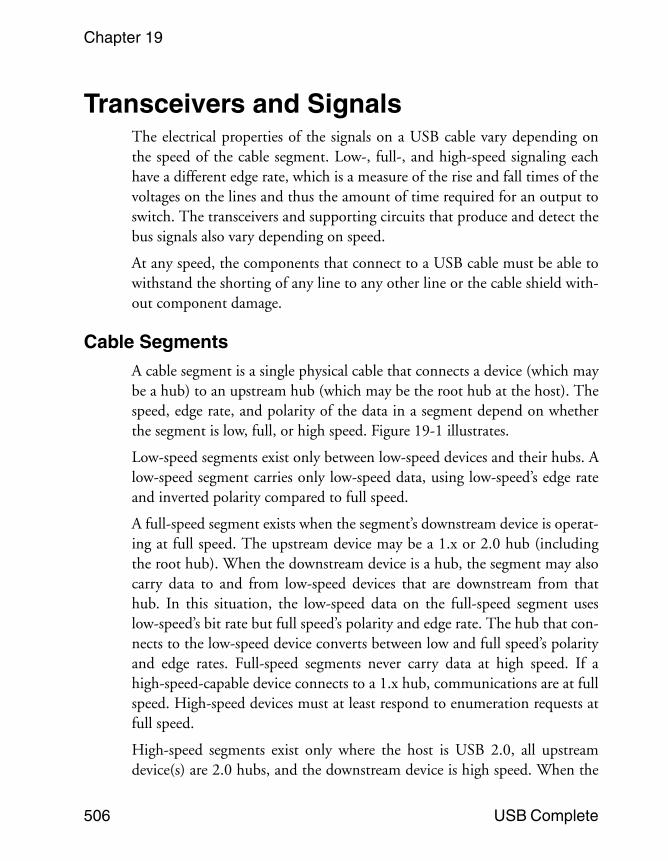
Cable SegmentsA cable segment is a single physical cable that connects a device (which maybe a hub) to an upstream hub (which may be the root hub at the host). Thespeed, edge rate, and polarity of the data in a segment depend on whetherthe segment is low, full, or high speed. Figure 19-1 illustrates.
Low-speed segments exist only between low-speed devices and their hubs. Alow-speed segment carries only low-speed data, using low-speed’s edge rateand inverted polarity compared to full speed.
A full-speed segment exists when the segment’s downstream device is operat-ing at full speed. The upstream device may be a 1.x or 2.0 hub (includingthe root hub). When the downstream device is a hub, the segment may alsocarry data to and from low-speed devices that are downstream from thathub. In this situation, the low-speed data on the full-speed segment useslow-speed’s bit rate but full speed’s polarity and edge rate. The hub that con-nects to the low-speed device converts between low and full speed’s polarityand edge rates. Full-speed segments never carry data at high speed. If ahigh-speed-capable device connects to a 1.x hub, communications are at fullspeed. High-speed devices must at least respond to enumeration requests atfull speed.
High-speed segments exist only where the host is USB 2.0, all upstreamdevice(s) are 2.0 hubs, and the downstream device is high speed. When the
The Electrical Interface
USB Complete 507
downstream device is a hub, the segment may also carry data to and fromlow- and full-speed devices that are downstream from that hub. All data in ahigh-speed segment travels at high speed, and the transaction translator in adownstream hub converts between low or full speed and high speed asneeded.
Figure 19-1: The speed of data in a segment depends on the capabilities of the device and its upstream hub.
Chapter 19
508 USB Complete
On attachment, all devices must communicate at low or full speed. Whenpossible, a high-speed-capable device transitions from full to high speedshortly after the device is attached, during the high-speed handshake.
Low- and Full-speed TransceiversThe transceiver for low and full speeds has a simpler design compared to thetransceiver for high speed.
Low- and Full-speed Differences
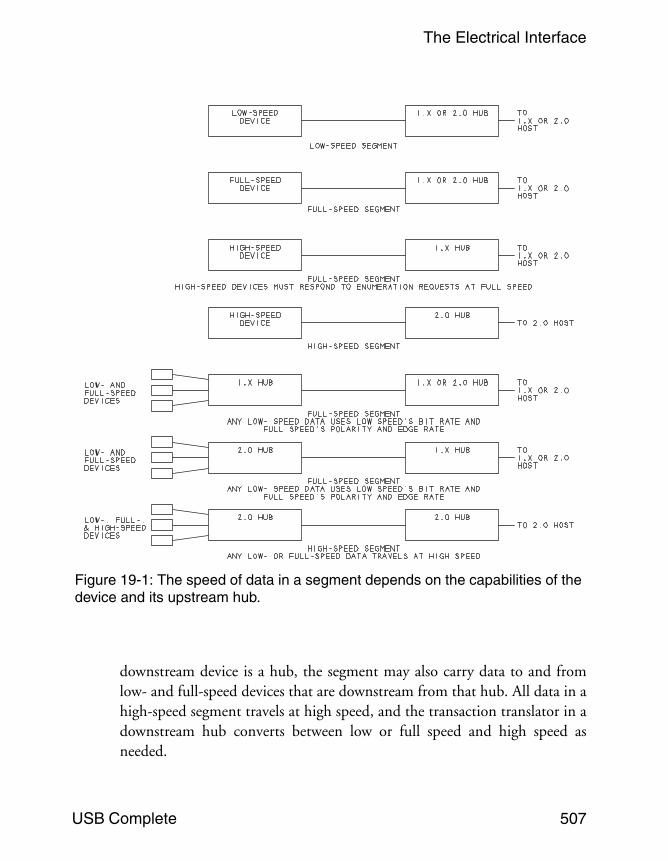
Low-speed data differs electrically from full speed in three ways. The bit rateis slower, at 1.5 Megabits/sec. compared to 12 Megabits/sec. for full speed.Low speed traffic’s polarity is inverted compared to full speed. And lowspeed has a slower edge rate compared to full speed. Figure 19-2 illustrates.The slower edge rate reduces reflected voltages on the line and makes it pos-sible to use cables that have less shielding and are thus cheaper to make andphysically more flexible.
The transceiver’s hardware doesn’t care about the signal polarity. The trans-ceiver just retransmits whatever logic levels are at its inputs. A driver thatsupports both speeds, such as a driver for a hub’s downstream port, must beable to switch between the two edge rates.
Figure 19-2: A 1.x hub converts between low- and full-speed’s polarities and edge rates. (Not drawn to scale)
The Electrical Interface
USB Complete 509
The Circuits
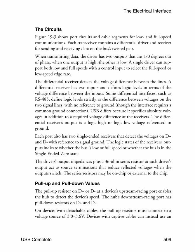
Figure 19-3 shows port circuits and cable segments for low- and full-speedcommunications. Each transceiver contains a differential driver and receiverfor sending and receiving data on the bus’s twisted pair.
When transmitting data, the driver has two outputs that are 180 degrees outof phase: when one output is high, the other is low. A single driver can sup-port both low and full speeds with a control input to select the full-speed orlow-speed edge rate.
The differential receiver detects the voltage difference between the lines. Adifferential receiver has two inputs and defines logic levels in terms of thevoltage difference between the inputs. Some differential interfaces, such asRS-485, define logic levels strictly as the difference between voltages on thetwo signal lines, with no reference to ground (though the interface requires acommon ground connection). USB differs because it specifies absolute volt-ages in addition to a required voltage difference at the receivers. The differ-ential receiver’s output is a logic-high or logic-low voltage referenced toground.
Each port also has two single-ended receivers that detect the voltages on D+and D- with reference to signal ground. The logic states of the receivers’ out-puts indicate whether the bus is low or full speed or whether the bus is in theSingle-Ended-Zero state.
The drivers’ output impedances plus a 36-ohm series resistor at each driver’soutput act as source terminations that reduce reflected voltages when theoutputs switch. The series resistors may be on-chip or external to the chip.
Pull-up and Pull-down Values
The pull-up resistor on D+ or D- at a device’s upstream-facing port enablesthe hub to detect the device’s speed. The hub’s downstream-facing port haspull-down resistors on D+ and D-.
On devices with detachable cables, the pull-up resistors must connect to avoltage source of 3.0–3.6V. Devices with captive cables can instead use an
Chapter 19
510 USB Complete
Figure 19-3: The downstream-facing ports on a 1.x hub must support both low and full speeds (except for ports with embedded or permanently attached devices). A device’s upstream-facing port typically supports just one speed.
The Electrical Interface
USB Complete 511
alternative means of termination, including connecting directly to VBUS. Inselecting an alternatative means of termination, the designer is responsiblefor ensuring that all of the bus’s signal levels meet the USB specification’srequirements.
An Engineering Change Notice titled Pull-up/pull-down resistors revises theUSB 2.0 specification by loosening the tolerances for pull-up and pull-downresistors that connect to a voltage source of 3.0–3.6V. The original valueswere 1.5 kilohms ±5% for the pull ups and 15 kilohms ±5% for the pulldowns. The tolerances were loosened to make it easier to include the resis-tors on chip without requiring laser trimming of the values. Using the loosertolerances increases complexity slightly at upstream-facing ports because thedevice must switch between two pull-up values depending on whether thebus is idle or active. But overall, the result can be reduced cost to devicemanufacturers.
Table 19-1 shows the new values. Devices that use the old tolerances remaincompliant, and devices that use the old tolerances can communicate withdevices that use the new tolerances. To use the wider tolerances, a devicemust use one pull-up value when the bus is idle and switch to a higher valuewhen the upstream device begins to transmit. The upper limit on the pullup for the idle bus ensures that the idle voltage is at least the required mini-mum of 2.7V. For the active bus, the lower limit is the same as the originallower limit and the upper limit ensures that the data line remains in a highstate if the receiver interprets noise as a Start-of-Packet signal.
Using the new limits, the resistors can have tolerances as high as 27%.Examples of compliant values are 19 kilohms ±25% for the pull downs and1200 and 2400 ohms ± 25% for the pull ups. A device can implement itspull up using two resistors in series, switching the second resistor into thecircuit when the upstream device begins to transmit. A device must switchto the higher resistance within 0.5 bit time of detecting a J-to-K transitionon the bus. To determine when to switch to the lower resistance, a devicemay use either or both of the following methods: on detecting a Sin-gle-ended Zero for more than 0.5 bit time or on detecting that the bus hasbeen in the J state for more than 7 bit times. The ECN details a few hard-ware implications for designers of chips that use the wider tolerances.
Chapter 19
512 USB Complete
High-speed TransceiversA high-speed device must support control requests at full speed, so thedevice must contain transceivers to support both full and high speeds andthe logic to switch between them. A high-speed-capable device’s upstreamtransceivers aren’t allowed to support low speed. In an external 2.0 hub, thedownstream transceivers at ports with user-accessible connectors must sup-port all three speeds.
Why 480 Megabits per Second?
High speed’s rate of 480 Megabits/sec. was chosen for several reasons. Thefrequency is slow enough to allow using the same cables and connectors asfull speed. Components can use CMOS processes and don’t require theadvanced compensation used in high-speed digital signal processors. Tests ofhigh-speed drivers showed 20 to 30 percent jitter at 480 Megabits/sec.Because receivers can be designed to tolerate 40 percent jitter, this bit rateallows a good margin of error. And 480 is an even multiple of 12, so a singlecrystal can support both full and high speed.
The use of separate drivers for high speed makes it easy to add high speed tothe existing interface. Current-mode drivers were chosen because they’refast.
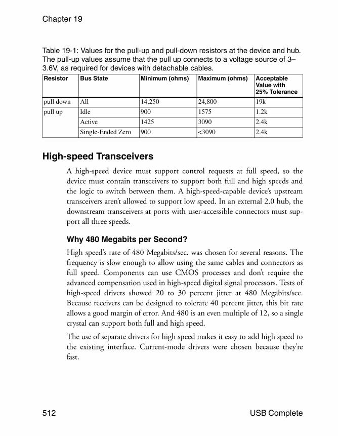
Table 19-1: Values for the pull-up and pull-down resistors at the device and hub. The pull-up values assume that the pull up connects to a voltage source of 3–3.6V, as required for devices with detachable cables.Resistor Bus State Minimum (ohms) Maximum (ohms) Acceptable
Value with 25% Tolerance
pull down All 14,250 24,800 19k
pull up Idle 900 1575 1.2k
Active 1425 3090 2.4k
Single-Ended Zero 900 <3090 2.4k
The Electrical Interface
USB Complete 513
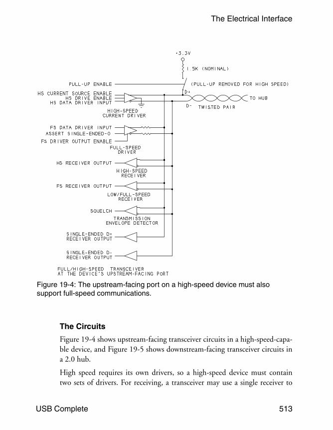
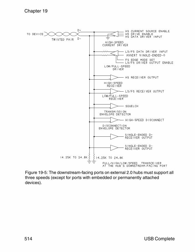
The Circuits
Figure 19-4 shows upstream-facing transceiver circuits in a high-speed-capa-ble device, and Figure 19-5 shows downstream-facing transceiver circuits ina 2.0 hub.
High speed requires its own drivers, so a high-speed device must containtwo sets of drivers. For receiving, a transceiver may use a single receiver to
Figure 19-4: The upstream-facing port on a high-speed device must also support full-speed communications.
Chapter 19
514 USB Complete
Figure 19-5: The downstream-facing ports on external 2.0 hubs must support all three speeds (except for ports with embedded or permanently attached devices).
The Electrical Interface
USB Complete 515
handle all supported speeds or separate receivers for low/full speed and highspeed.
When a high-speed driver sends data, a current source drives one line withthe other line at ground. The current source may be active all the time oronly when transmitting. A current source that is active all the time is easierto design but consumes more power. The USB specification requires devicesto meet the signal-amplitude and timing requirements beginning with thefirst symbol in a packet. This requirement complicates the design of a cur-rent source that is active only when transmitting. If the driver instead keepsits current source active all the time, the driver can direct the current toground when not transmitting on the bus.
In a high-speed-capable transceiver, the output impedance of the full-speeddrivers has tighter tolerance compared to full-speed-only drivers (45 ohms±10%, compared to 36 ohms ±22%). The change is required because thehigh-speed bus uses the full-speed drivers as electrical terminations on thecable. Full-speed drivers that aren’t part of a high-speed transceiver don’trequire a change in output impedance.
When the high-speed drivers are active, the full-speed drivers bring bothdata lines low (the Single-ended-Zero state). Each driver and its series resis-tor then function as a 45-ohm termination to ground. Because there is adriver at each end of the cable segment, there is a termination at both thesource and the load. This double termination quiets the line more effectivelythan the source-only series terminations in full-speed segments. Using thefull-speed drivers as terminations means no extra components are required.
The USB specification provides eye-pattern templates that show therequired high-speed transmitter outputs and receiver sensitivity. High-speedreceivers must also meet new specifications that require the use of a differen-tial time-domain reflectometer (TDR) to measure impedance characteris-tics.
All high-speed receivers must include a differential envelope detector todetect the Squelch (invalid signal) state, indicated by a differential bus volt-age of 100 millivolts or less. The downstream ports on all 2.0 hubs must also
Chapter 19
516 USB Complete
include a high-speed-disconnect detector that detects when a device hasbeen removed from the bus.
Other new responsibilities for high-speed-capable devices include managingthe switch from full to high speed and handling new protocols for enteringand exiting the Suspend and Reset states.
Switching Speeds
In a low- or full-speed device, a pull-up resistor on one of the signal linesindicates device speed. When a low- or full-speed device is attached orremoved from the bus, the voltage change due to the pull up informs thehub of the change. High-speed-capable devices always attach at full speed,so hubs detect attachment of high-speed-capable devices in the same way.
As Chapter 18 explained, the switch to high speed occurs after the devicehas been detected, during the Reset sent by the hub. A high-speed-capabledevice must support the high-speed handshake that informs the hub thatthe device is capable of high speed. When switching to high speed, thedevice removes its pull up from the bus.
Detecting Removal of a High-speed Device
A 2.0 hub must also detect the removal of a high-speed device. Because thedevice has no pull up at high speed, the hub has to use a different method todetect the removal. When a device is removed from the bus, the differentialterminations are removed, and the removal causes the differential voltage atthe hub’s port to double. On detecting the doubled voltage, the hub knowsthe device has been removed.
The hub detects the voltage by measuring the differential bus voltage duringthe extended End of High-speed Packet (HSEOP) in each high-speedStart-of-Frame Packet (HSSOP). A differential voltage of at least 625 milli-volts indicates a disconnect.
Suspending and Resuming at High Speed
As Chapter 16 explained, devices must enter the low-power Suspend statewhen the bus has been in the Idle state for at least 3 milliseconds and no
The Electrical Interface
USB Complete 517
more than 10 milliseconds. When the bus has been idle for 3 milliseconds, ahigh-speed device switches to full speed. The device then checks the state ofthe full-speed bus to determine whether the host is requesting a Suspend orReset. If the bus state is Single-Ended Zero, the host is requesting a Reset, sothe device prepares for the high-speed-detect handshake. If the bus state isIdle, the device enters the Suspend state. The device must return to highspeed on exiting the Suspend state.
Signal VoltagesChapter 18 introduced USB’s bus states. The voltages that define the statesvary depending on the speed of the cable segment. The differences in thespecified voltages at the transmitter and receiver mean that a signal can havesome noise or attenuation and the receiver will still see the correct logiclevel.
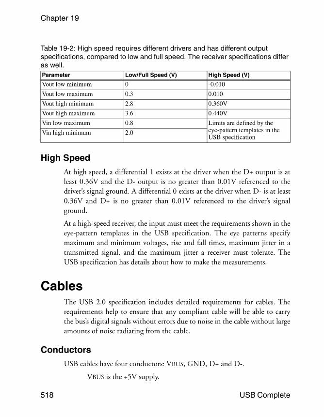
Low and Full SpeedsTable 19-2 shows the driver output voltages for low/full and high speeds. Atlow and full speeds, a Differential 1 exists at the driver when the D+ outputis at least 2.8V and the D- output is no greater than 0.3V referenced to thedriver’s signal ground. A differential 0 exists at the driver when D- is at least2.8V and D+ is no greater than 0.3V referenced to the driver’s signalground.
At a low- or full-speed receiver, a differential 1 exists when D+ is at least 2Vreferenced to the receiver’s signal ground, and the difference between D+and D- is greater than 200 millivolts. A differential 0 exists when D- is atleast 2V referenced to the receiver’s signal ground, and the differencebetween D- and D+ is greater than 200 millivolts. However, a receiver mayoptionally have less stringent definitions that require only a differential volt-age greater than 200 millivolts, ignoring the requirement for one line to beat least 2V.
Chapter 19
518 USB Complete
High SpeedAt high speed, a differential 1 exists at the driver when the D+ output is atleast 0.36V and the D- output is no greater than 0.01V referenced to thedriver’s signal ground. A differential 0 exists at the driver when D- is at least0.36V and D+ is no greater than 0.01V referenced to the driver’s signalground.
At a high-speed receiver, the input must meet the requirements shown in theeye-pattern templates in the USB specification. The eye patterns specifymaximum and minimum voltages, rise and fall times, maximum jitter in atransmitted signal, and the maximum jitter a receiver must tolerate. TheUSB specification has details about how to make the measurements.
CablesThe USB 2.0 specification includes detailed requirements for cables. Therequirements help to ensure that any compliant cable will be able to carrythe bus’s digital signals without errors due to noise in the cable without largeamounts of noise radiating from the cable.
ConductorsUSB cables have four conductors: VBUS, GND, D+ and D-.
VBUS is the +5V supply.
Table 19-2: High speed requires different drivers and has different output specifications, compared to low and full speed. The receiver specifications differ as well.Parameter Low/Full Speed (V) High Speed (V)
Vout low minimum 0 -0.010
Vout low maximum 0.3 0.010
Vout high minimum 2.8 0.360V
Vout high maximum 3.6 0.440V
Vin low maximum 0.8 Limits are defined by the eye-pattern templates in the USB specification
Vin high minimum 2.0
The Electrical Interface
USB Complete 519
GND is the ground reference for VBUS as well as for D+ and D-.D+ and D- are the differential signal pair.
Chapter 16 described the voltage and current limits for VBUS.
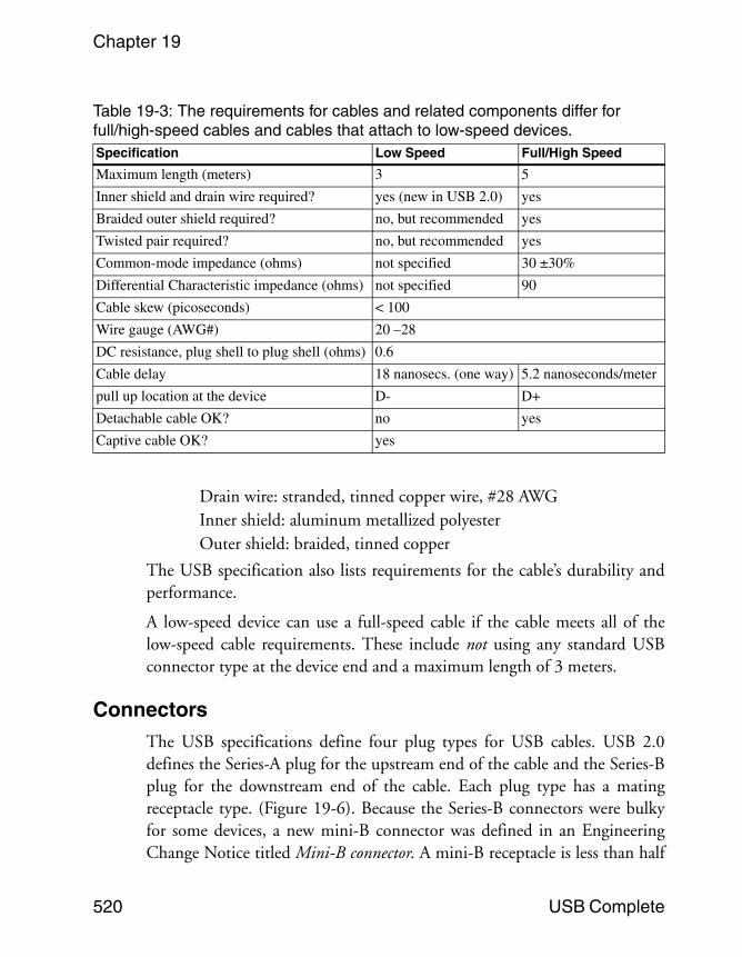
Cables to be used in full- or high-speed segments have different require-ments compared to cables for low-speed segments. Table 19-3 compares thetwo cable types. A low-speed segment is a cable segment between alow-speed device and its hub. Any additional upstream segments betweenhubs are considered to be full- or high-speed segments.
The USB 2.0 specification tightened the requirements for low-speed cables.A 1.1-compliant low-speed cable required no shielding at all. A 2.0-compli-ant low-speed cable must have the same inner shield and drain wire requiredfor full speed. The USB specification also recommends, but doesn’t require,a braided outer shield and a twisted pair for data, as on full- and high-speedcables.
Full- and high-speed segments can use the same cables. When the USB 2.0specification was under development, an Engineering Change Notice to the1.x specification added new requirements to ensure that full-speed cableswould also work at high speed. The 2.0 specification also includes theserequirements. The requirements describe what was typically found in com-pliant full-speed cables, so most providers with compliant cables had nochanges to make to their products.
In a full/high-speed cable, the signal wires must have a differential character-istic impedance of 90 ohms. This value is a measure of the input impedanceof an infinite, open line and determines the initial current on the lines whenthe outputs switch. The characteristic impedance for a low-speed cable isn’tdefined because the slower edge rates mean that the initial current doesn’taffect the logic states seen by the receiver.
The USB specification lists requirements for the cable’s conductors, shield-ing, and insulation. These are the major requirements for full/high-speedcables:
Data wires: twisted pair, #28 AWG.Power and ground: non-twisted, #20 to #28 AWG.
Chapter 19
520 USB Complete
Drain wire: stranded, tinned copper wire, #28 AWGInner shield: aluminum metallized polyesterOuter shield: braided, tinned copper
The USB specification also lists requirements for the cable’s durability andperformance.
A low-speed device can use a full-speed cable if the cable meets all of thelow-speed cable requirements. These include not using any standard USBconnector type at the device end and a maximum length of 3 meters.
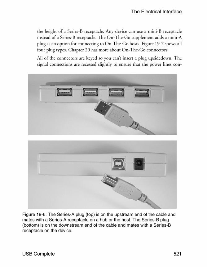
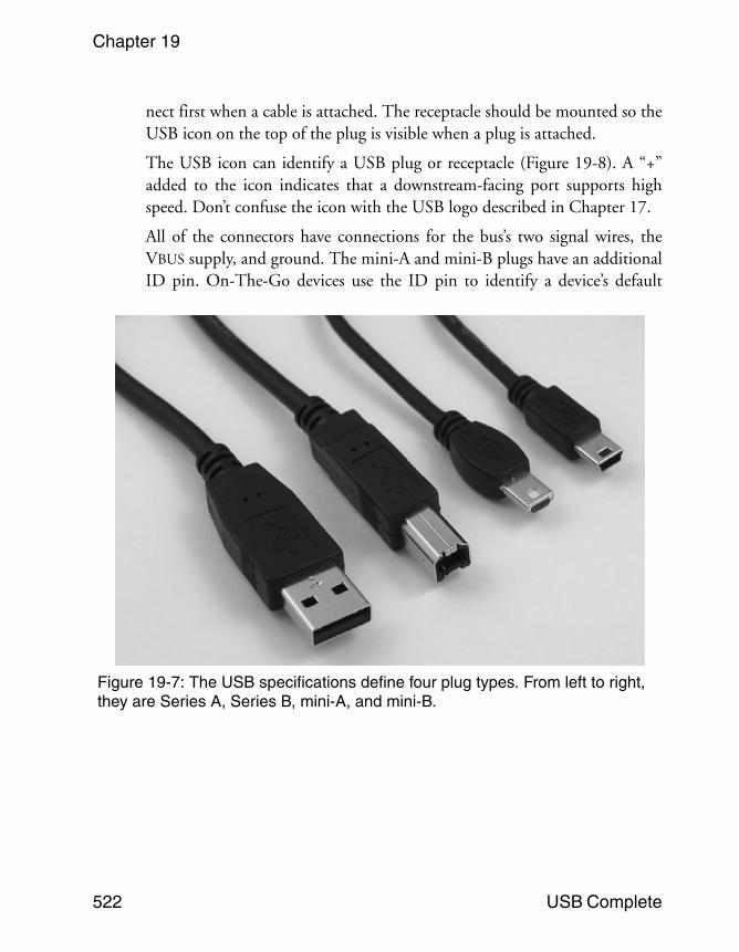
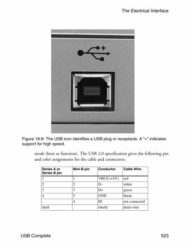
ConnectorsThe USB specifications define four plug types for USB cables. USB 2.0defines the Series-A plug for the upstream end of the cable and the Series-Bplug for the downstream end of the cable. Each plug type has a matingreceptacle type. (Figure 19-6). Because the Series-B connectors were bulkyfor some devices, a new mini-B connector was defined in an EngineeringChange Notice titled Mini-B connector. A mini-B receptacle is less than half
Table 19-3: The requirements for cables and related components differ for full/high-speed cables and cables that attach to low-speed devices.Specification Low Speed Full/High Speed
Maximum length (meters) 3 5
Inner shield and drain wire required? yes (new in USB 2.0) yes
Braided outer shield required? no, but recommended yes
Twisted pair required? no, but recommended yes
Common-mode impedance (ohms) not specified 30 ±30%
Differential Characteristic impedance (ohms) not specified 90
Cable skew (picoseconds) < 100
Wire gauge (AWG#) 20 –28
DC resistance, plug shell to plug shell (ohms) 0.6
Cable delay 18 nanosecs. (one way) 5.2 nanoseconds/meter
pull up location at the device D- D+
Detachable cable OK? no yes
Captive cable OK? yes
The Electrical Interface
USB Complete 521
the height of a Series-B receptacle. Any device can use a mini-B receptacleinstead of a Series-B receptacle. The On-The-Go supplement adds a mini-Aplug as an option for connecting to On-The-Go hosts. Figure 19-7 shows allfour plug types. Chapter 20 has more about On-The-Go connectors.
All of the connectors are keyed so you can’t insert a plug upsidedown. Thesignal connections are recessed slightly to ensure that the power lines con-
Figure 19-6: The Series-A plug (top) is on the upstream end of the cable and mates with a Series-A receptacle on a hub or the host. The Series-B plug (bottom) is on the downstream end of the cable and mates with a Series-B receptacle on the device.
Chapter 19
522 USB Complete
nect first when a cable is attached. The receptacle should be mounted so theUSB icon on the top of the plug is visible when a plug is attached.
The USB icon can identify a USB plug or receptacle (Figure 19-8). A “+”added to the icon indicates that a downstream-facing port supports highspeed. Don’t confuse the icon with the USB logo described in Chapter 17.
All of the connectors have connections for the bus’s two signal wires, theVBUS supply, and ground. The mini-A and mini-B plugs have an additionalID pin. On-The-Go devices use the ID pin to identify a device’s default
Figure 19-7: The USB specifications define four plug types. From left to right, they are Series A, Series B, mini-A, and mini-B.
The Electrical Interface
USB Complete 523
mode (host or function). The USB 2.0 specification gives the following pinand color assignments for the cable and connectors:
Series A or Series B pin
Mini-B pin Conductor Cable Wire
1 1 VBUS (+5V) red
2 2 D- white
3 3 D+ green
4 5 GND black
- 4 ID not connected
shell shield drain wire
Figure 19-8: The USB icon identifies a USB plug or receptacle. A “+” indicates support for high speed.


![[99-102 updated] Graphical User Interface for Electrical](https://img.pdfslide.net/doc/110x75/619d38b6048df4630517b80c/99-102-updated-graphical-user-interface-for-electrical-.jpg)