Embed Size (px)
Citation preview
The electro-mechanicalpower steering system
Design and Function
Self-Study Programme 225
Service.
2
The Self-Study Programme explains the design and function of new developments! The contents of this SSP are not updated.
Please always refer to the relevant Service Literaturefor all inspection, adjustment and repair instructions.
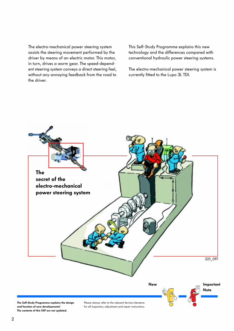
The electro-mechanical power steering system assists the steering movement performed by the driver by means of an electric motor. This motor, in turn, drives a worm gear. The speed-depend-ent steering system conveys a direct steering feel, without any annoying feedback from the road to the driver.
This Self-Study Programme explains this new technology and the differences compared with conventional hydraulic power steering systems.
The electro-mechanical power steering system is currently fitted to the Lupo 3L TDI.
The secret of theelectro-mechanicalpower steering system
New ImportantNote
225_097
3
Table of contents
Introduction . . . . . . . . . . . . . . . . . . . . . . . . . . . . . . . . . . 4
The steering mechanism . . . . . . . . . . . . . . . . . . . . . . . . 8
System overview . . . . . . . . . . . . . . . . . . . . . . . . . . . . 12
The electronics of the steering system . . . . . . . . . . . . 13
Functional description. . . . . . . . . . . . . . . . . . . . . . . . . 18
Function diagram . . . . . . . . . . . . . . . . . . . . . . . . . . . . . 21
Service . . . . . . . . . . . . . . . . . . . . . . . . . . . . . . . . . . . . . 22
Test your knowledge . . . . . . . . . . . . . . . . . . . . . . . . . . .23
4
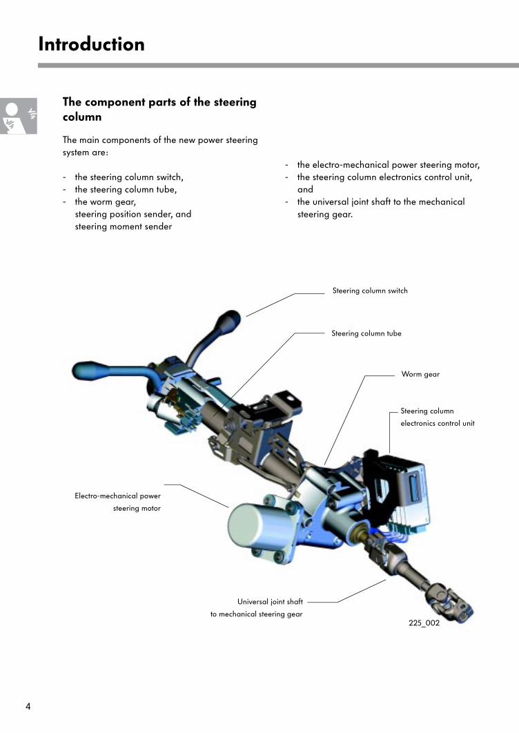
The component parts of the steering column
The main components of the new power steering system are:
- the steering column switch,- the steering column tube,- the worm gear,
steering position sender, and steering moment sender
- the electro-mechanical power steering motor,- the steering column electronics control unit,
and- the universal joint shaft to the mechanical
steering gear.
Introduction
Steering column switch
Steering column tube
Worm gear
Steering column
electronics control unit
Electro-mechanical power
steering motor
Universal joint shaft
to mechanical steering gear225_002
5
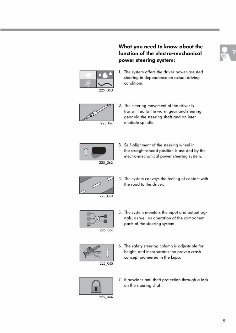
What you need to know about the function of the electro-mechanical power steering system:
1. The system offers the driver power-assistedsteering in dependence on actual driving conditions
2. The steering movement of the driver is transmitted to the worm gear and steeringgear via the steering shaft and an inter-mediate spindle.
3. Self-alignment of the steering wheel in the straight-ahead position is assisted by the electro-mechanical power steering system.
4. The system conveys the feeling of contact withthe road to the driver.
5. The system monitors the input and output sig-nals, as well as operation of the componentparts of the steering system.
6. The safety steering column is adjustable forheight, and incorporates the proven crash concept pioneered in the Lupo.
7. It provides anti-theft protection through a lockon the steering shaft.
225_061
225_062
225_063
225_066
225_065
225_064
225_060
Introduction
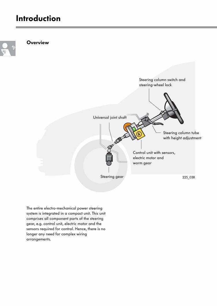
Steering column switch andsteering-wheel lock
Steering column tube with height adjustment
Control unit with sensors,electric motor andworm gear
Universal joint shaft
Overview
Steering gear
The entire electro-mechanical power steering system is integrated in a compact unit. This unit comprises all component parts of the steering gear, e.g. control unit, electric motor and thesensors required for control. Hence, there is no longer any need for complex wiringarrangements.
225_038
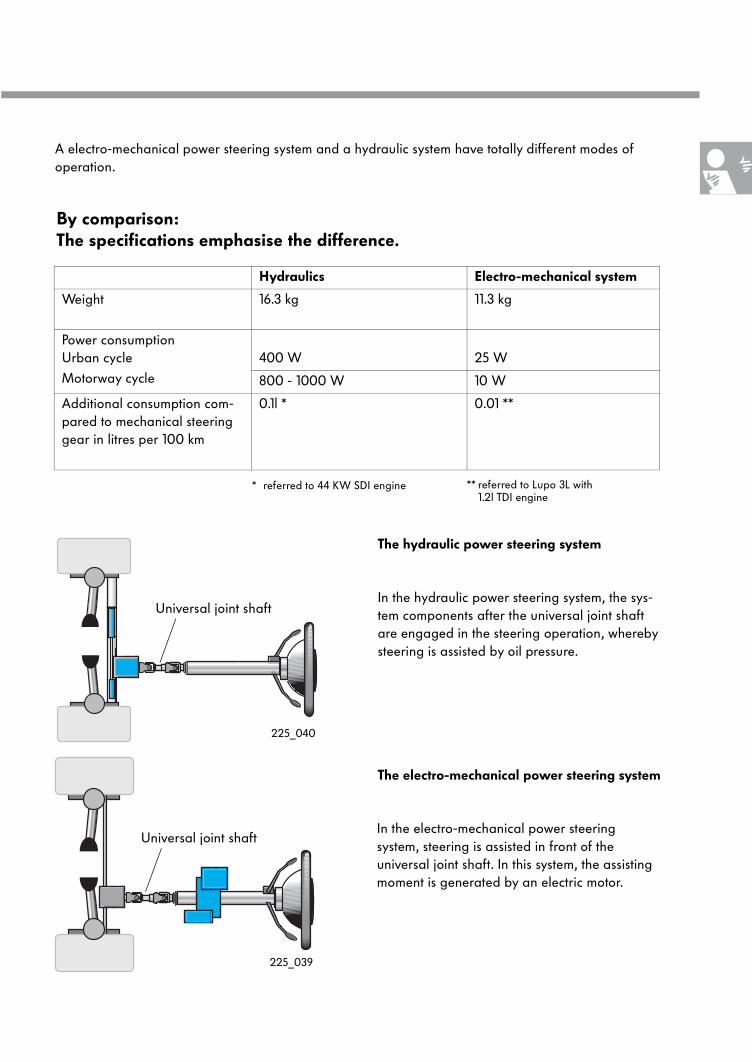
Hydraulics Electro-mechanical system
Weight 16.3 kg 11.3 kg
Power consumption Urban cycle
Motorway cycle
400 W 25 W
800 - 1000 W 10 W
Additional consumption com-pared to mechanical steering gear in litres per 100 km
0.1l * 0.01 **
* referred to 44 KW SDI engine ** referred to Lupo 3L with 1.2l TDI engine
The electro-mechanical power steering system
In the hydraulic power steering system, the sys-tem components after the universal joint shaft are engaged in the steering operation, whereby steering is assisted by oil pressure.
In the electro-mechanical power steering system, steering is assisted in front of the universal joint shaft. In this system, the assisting moment is generated by an electric motor.
By comparison:The specifications emphasise the difference.
The hydraulic power steering system
A electro-mechanical power steering system and a hydraulic system have totally different modes of operation.
Universal joint shaft
Universal joint shaft
225_039
225_040
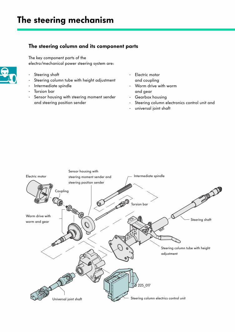
The steering column and its component parts
The key component parts of the electro/mechanical power steering system are:
- Steering shaft- Steering column tube with height adjustment- Intermediate spindle- Torsion bar- Sensor housing with steering moment sender
and steering position sender
- Electric motorand coupling
- Worm drive with wormand gear
- Gearbox housing - Steering column electronics control unit and- universal joint shaft
The steering mechanism
Worm drive with
worm and gear
Electric motorSensor housing with
steering moment sender and
steering position sender
Torsion bar
Intermediate spindle
Universal joint shaft Steering column electrics control unit
Steering shaft
Steering column tube with height
adjustment
Coupling
225_017
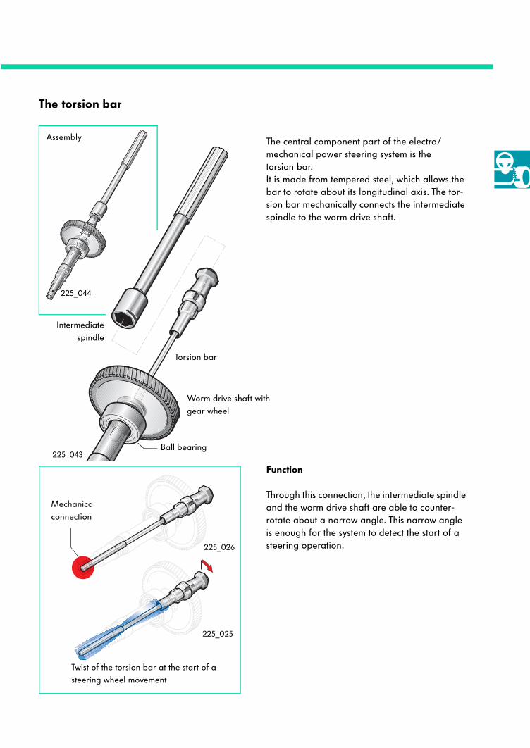
The torsion bar
The central component part of the electro/mechanical power steering system is the torsion bar. It is made from tempered steel, which allows the bar to rotate about its longitudinal axis. The tor-sion bar mechanically connects the intermediate spindle to the worm drive shaft.
Function
Through this connection, the intermediate spindle and the worm drive shaft are able to counter-rotate about a narrow angle. This narrow angle is enough for the system to detect the start of a steering operation.
Torsion bar
Worm drive shaft with gear wheel
Intermediatespindle
Assembly
Mechanical connection
Twist of the torsion bar at the start of a steering wheel movement
Ball bearing
225_044
225_043
225_026
225_025
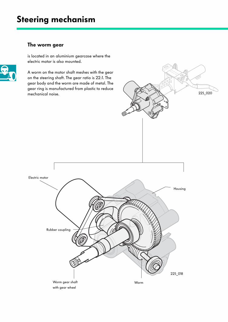
The worm gear
is located in an aluminium gearcase where the electric motor is also mounted.
A worm on the motor shaft meshes with the gear on the steering shaft. The gear ratio is 22:1. The gear body and the worm are made of metal. The gear ring is manufactured from plastic to reduce mechanical noise.
Steering mechanism
Electric motor
Rubber coupling
Housing
Worm gear shaft
with gear wheelWorm
225_018
225_020
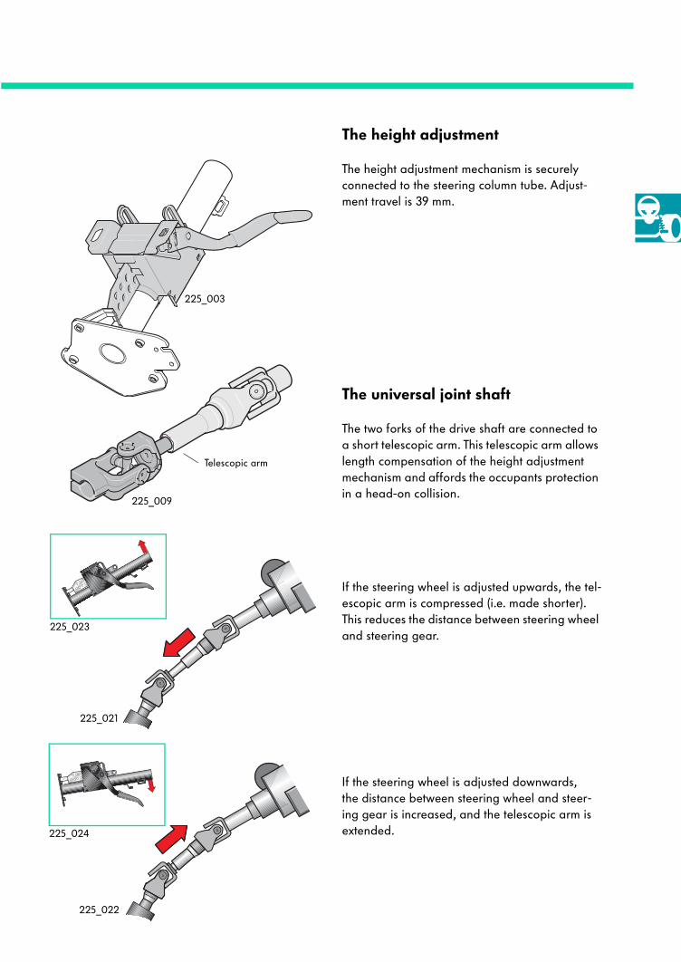
The height adjustment
The height adjustment mechanism is securely connected to the steering column tube. Adjust-ment travel is 39 mm.
The universal joint shaft
The two forks of the drive shaft are connected to a short telescopic arm. This telescopic arm allows length compensation of the height adjustment mechanism and affords the occupants protection in a head-on collision.
If the steering wheel is adjusted upwards, the tel-escopic arm is compressed (i.e. made shorter). This reduces the distance between steering wheel and steering gear.
If the steering wheel is adjusted downwards, the distance between steering wheel and steer-ing gear is increased, and the telescopic arm is extended.
Telescopic arm
225_022
225_024
225_023
225_021
225_009
225_003
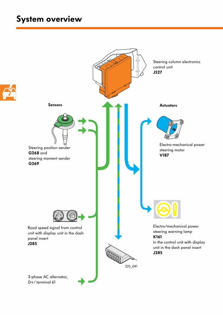
System overview
Sensors Actuators
Steering position sender G268 andsteering moment sender G269
Electro-mechanical power steering motorV187
Steering column electronics control unitJ527
Electro/mechanical power steering warning lampK161in the control unit with display unit in the dash panel insertJ285
3-phase AC alternator, D+/ terminal 61
Road speed signal from control unit with display unit in the dash panel insertJ285
225_041
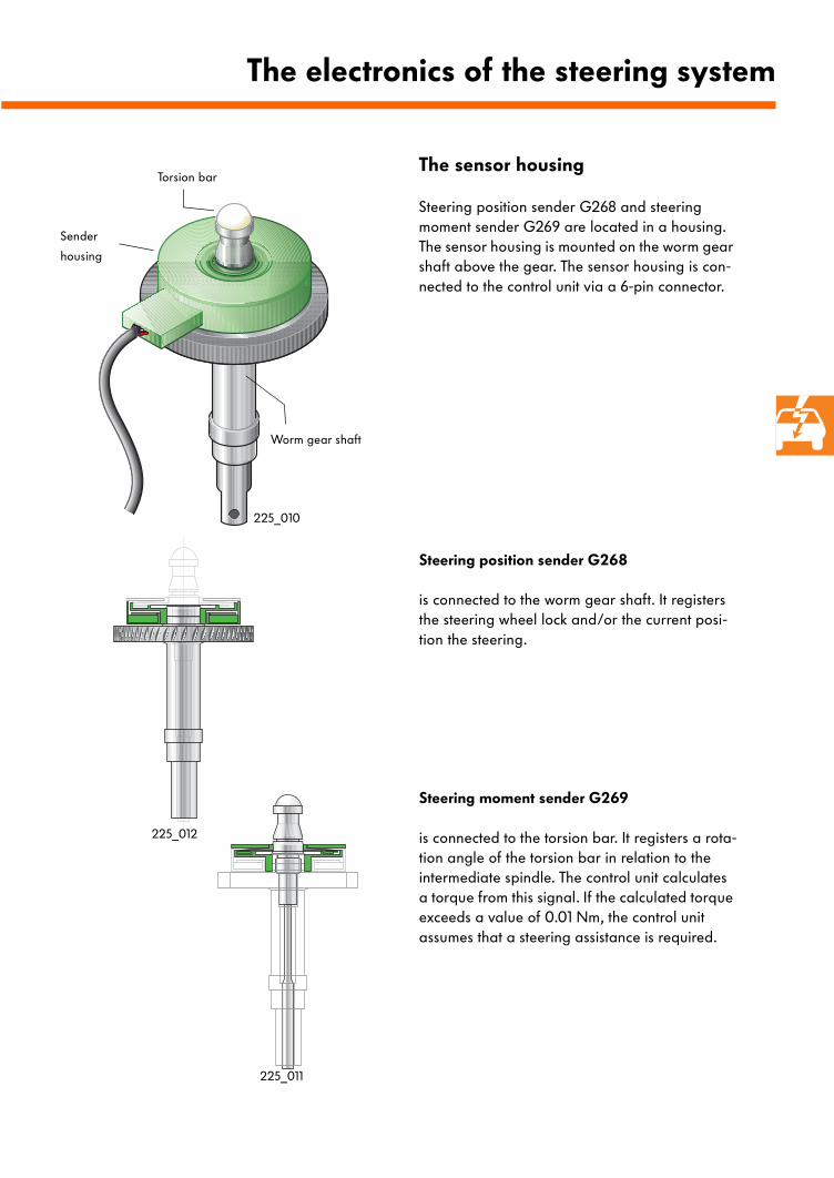
The sensor housing
Steering position sender G268 and steering moment sender G269 are located in a housing. The sensor housing is mounted on the worm gear shaft above the gear. The sensor housing is con-nected to the control unit via a 6-pin connector.
The electronics of the steering system
Worm gear shaft
Sender
housing
Torsion bar
Steering position sender G268
is connected to the worm gear shaft. It registers the steering wheel lock and/or the current posi-tion the steering.
Steering moment sender G269
is connected to the torsion bar. It registers a rota-tion angle of the torsion bar in relation to the intermediate spindle. The control unit calculates a torque from this signal. If the calculated torque exceeds a value of 0.01 Nm, the control unit assumes that a steering assistance is required.
225_011
225_012
225_010
The electronics of the steering system
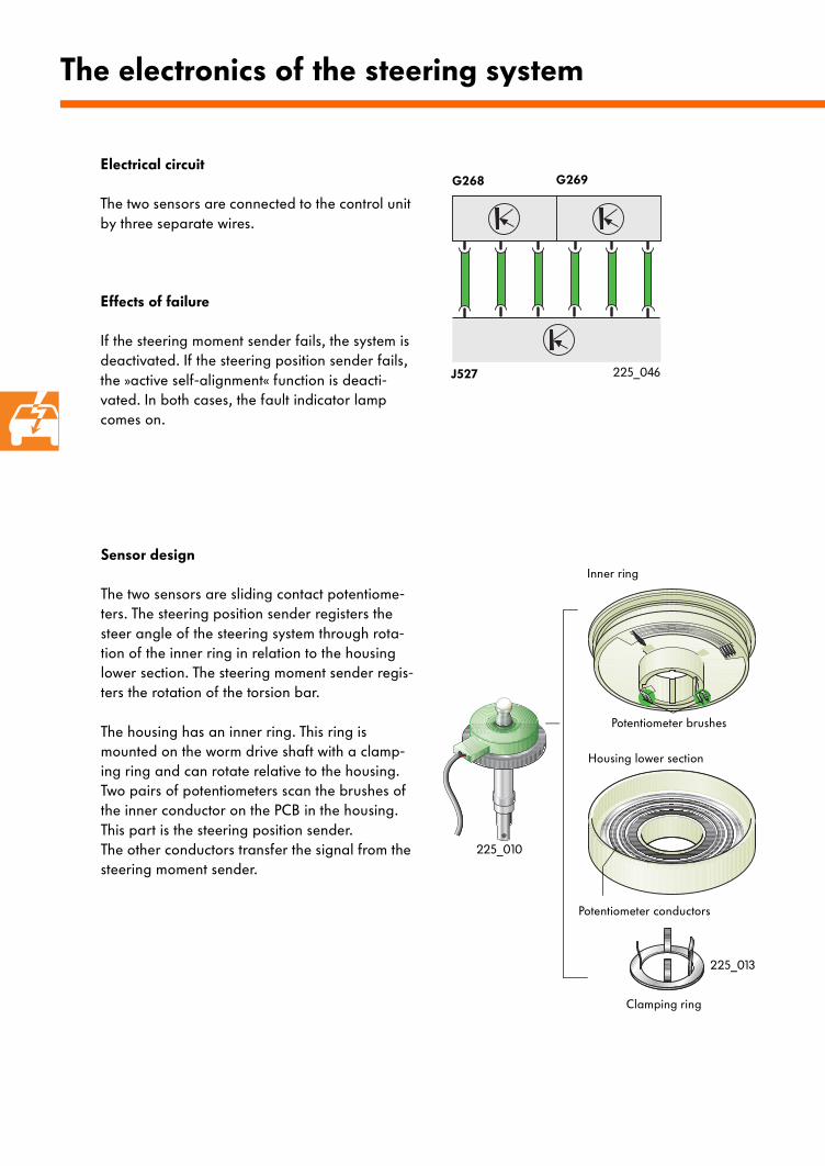
Sensor design
The two sensors are sliding contact potentiome-ters. The steering position sender registers the steer angle of the steering system through rota-tion of the inner ring in relation to the housing lower section. The steering moment sender regis-ters the rotation of the torsion bar.
The housing has an inner ring. This ring is mounted on the worm drive shaft with a clamp-ing ring and can rotate relative to the housing. Two pairs of potentiometers scan the brushes of the inner conductor on the PCB in the housing. This part is the steering position sender. The other conductors transfer the signal from the steering moment sender.
Clamping ring
Inner ring
Potentiometer brushes
Housing lower section
Potentiometer conductors
Electrical circuit
The two sensors are connected to the control unit by three separate wires.
Effects of failure
If the steering moment sender fails, the system is deactivated. If the steering position sender fails, the »active self-alignment« function is deacti-vated. In both cases, the fault indicator lamp comes on.
G268 G269
J527
225_010
225_013
225_046
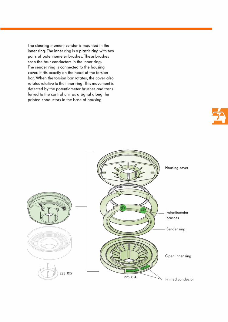
The steering moment sender is mounted in the inner ring. The inner ring is a plastic ring with two pairs of potentiometer brushes. These brushes scan the four conductors in the inner ring. The sender ring is connected to the housing cover. It fits exactly on the head of the torsion bar. When the torsion bar rotates, the cover also rotates relative to the inner ring. This movement is detected by the potentiometer brushes and trans-ferred to the control unit as a signal along the printed conductors in the base of housing.
Housing cover
Sender ring
Potentiometer brushes
Open inner ring
Printed conductor225_014225_015
The electronics of the steering system
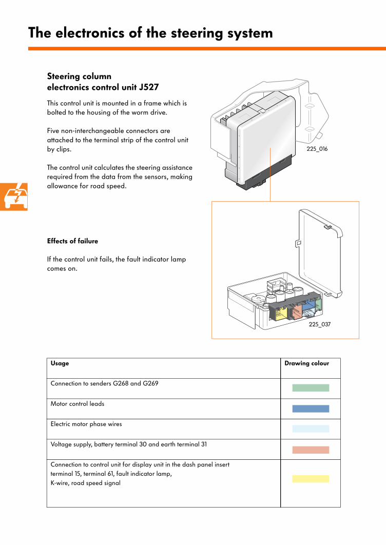
Steering columnelectronics control unit J527
This control unit is mounted in a frame which is bolted to the housing of the worm drive.
Five non-interchangeable connectors are attached to the terminal strip of the control unit by clips.
The control unit calculates the steering assistance required from the data from the sensors, making allowance for road speed.
Effects of failure
If the control unit fails, the fault indicator lamp comes on.
Usage Drawing colour
Connection to senders G268 and G269
Motor control leads
Electric motor phase wires
Voltage supply, battery terminal 30 and earth terminal 31
Connection to control unit for display unit in the dash panel insertterminal 15, terminal 61, fault indicator lamp, K-wire, road speed signal
225_016
225_037
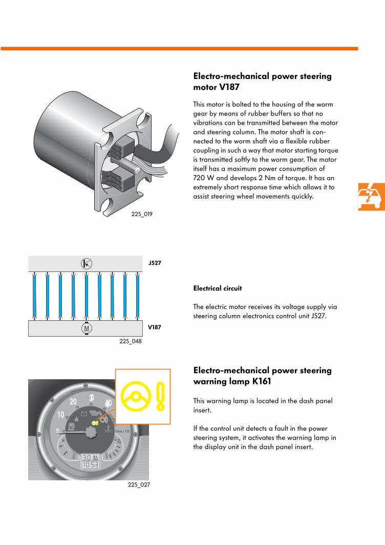
Electro-mechanical power steering motor V187
This motor is bolted to the housing of the worm gear by means of rubber buffers so that no vibrations can be transmitted between the motor and steering column. The motor shaft is con-nected to the worm shaft via a flexible rubber coupling in such a way that motor starting torque is transmitted softly to the worm gear. The motor itself has a maximum power consumption of 720 W and develops 2 Nm of torque. It has an extremely short response time which allows it to assist steering wheel movements quickly.
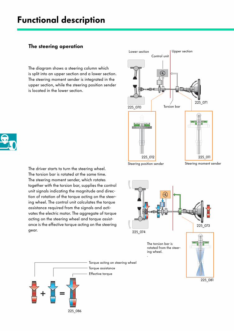
Electrical circuit
The electric motor receives its voltage supply via steering column electronics control unit J527.
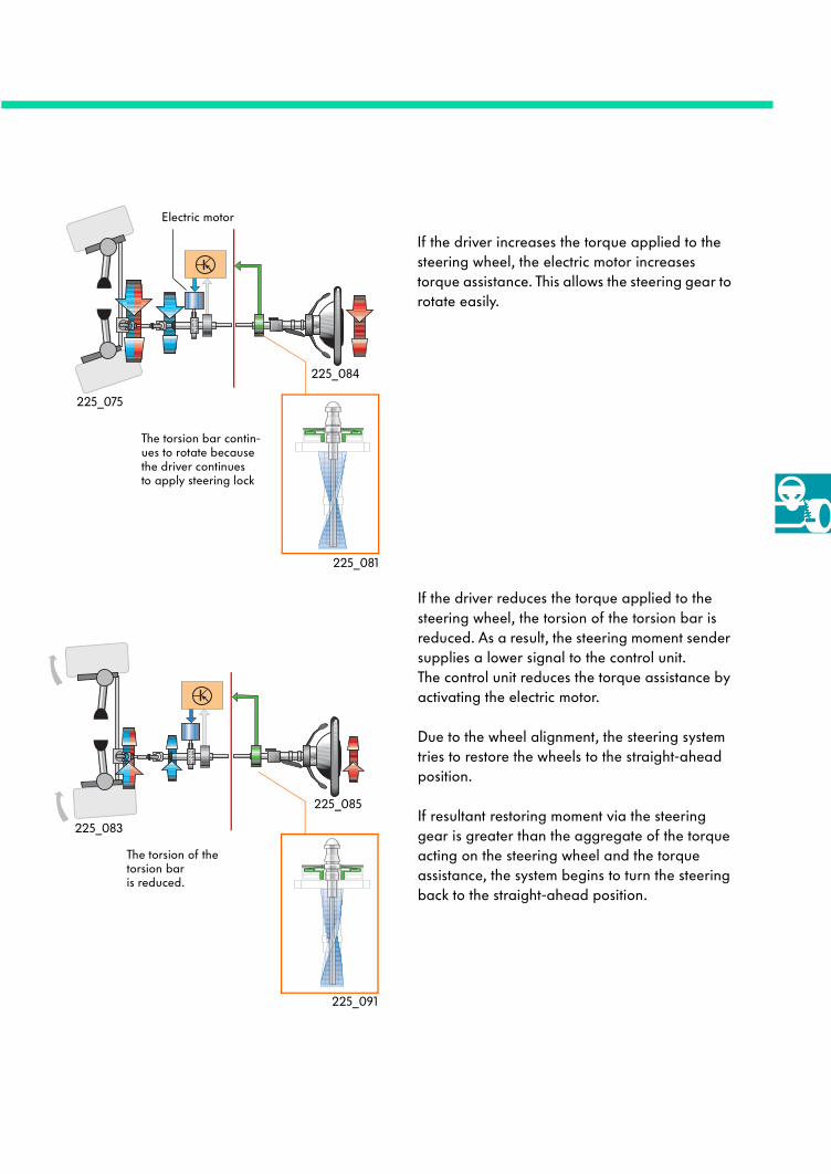
Electro-mechanical power steering warning lamp K161
This warning lamp is located in the dash panel insert.
If the control unit detects a fault in the power steering system, it activates the warning lamp in the display unit in the dash panel insert.
J527
V187
225_027
225_048
225_019
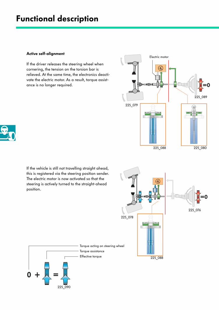
The steering operation
Functional description
Lower section
Steering moment senderSteering position sender
Upper section
Torsion bar
Control unit
The torsion bar is rotated from the steer-ing wheel. .
The diagram shows a steering column whichis split into an upper section and a lower section. The steering moment sender is integrated in the upper section, while the steering position sender is located in the lower section.
The driver starts to turn the steering wheel. The torsion bar is rotated at the same time. The steering moment sender, which rotates together with the torsion bar, supplies the control unit signals indicating the magnitude and direc-tion of rotation of the torque acting on the steer-ing wheel. The control unit calculates the torque assistance required from the signals and acti-vates the electric motor. The aggregate of torque acting on the steering wheel and torque assist-ance is the effective torque acting on the steering gear.
Torque acting on steering wheel
Torque assistance
Effective torque
225_086
225_081
225_074
225_073
225_012 225_011
225_071225_070
Electric motor
The torsion bar contin-ues to rotate because the driver continuesto apply steering lock
The torsion of the torsion bar is reduced.
If the driver increases the torque applied to the steering wheel, the electric motor increases torque assistance. This allows the steering gear to rotate easily.
If the driver reduces the torque applied to the steering wheel, the torsion of the torsion bar is reduced. As a result, the steering moment sender supplies a lower signal to the control unit.The control unit reduces the torque assistance by activating the electric motor.
Due to the wheel alignment, the steering system tries to restore the wheels to the straight-ahead position.
If resultant restoring moment via the steering gear is greater than the aggregate of the torque acting on the steering wheel and the torque assistance, the system begins to turn the steering back to the straight-ahead position.
225_091
225_083
225_085
225_075
225_084
225_081
Functional description
Electric motorActive self-alignment
If the driver releases the steering wheel when cornering, the tension on the torsion bar is relieved. At the same time, the electronics deacti-vate the electric motor. As a result, torque assist-ance is no longer required.
If the vehicle is still not travelling straight ahead, this is registered via the steering position sender. The electric motor is now activated so that the steering is actively turned to the straight-ahead position.
Torque acting on steering wheel
Torque assistance
Effective torque 225_088
225_090
225_078
225_076
225_088 225_080
225_089
225_079
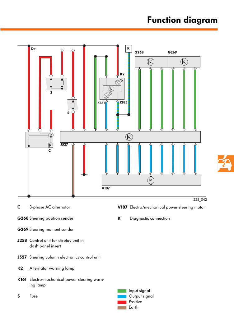
C 3-phase AC alternator
G268 Steering position sender
G269 Steering moment sender
J258 Control unit for display unit in dash panel insert
J527 Steering column electronics control unit
K2 Alternator warning lamp
K161 Electro-mechanical power steering warn-ing lamp
S Fuse
V187 Electro/mechanical power steering motor
K Diagnostic connection
Function diagram
G268 G269
J285K161
S
V187
J527
S
C
K
K2
D+
225_042
Input signalOutput signalPositiveEarth
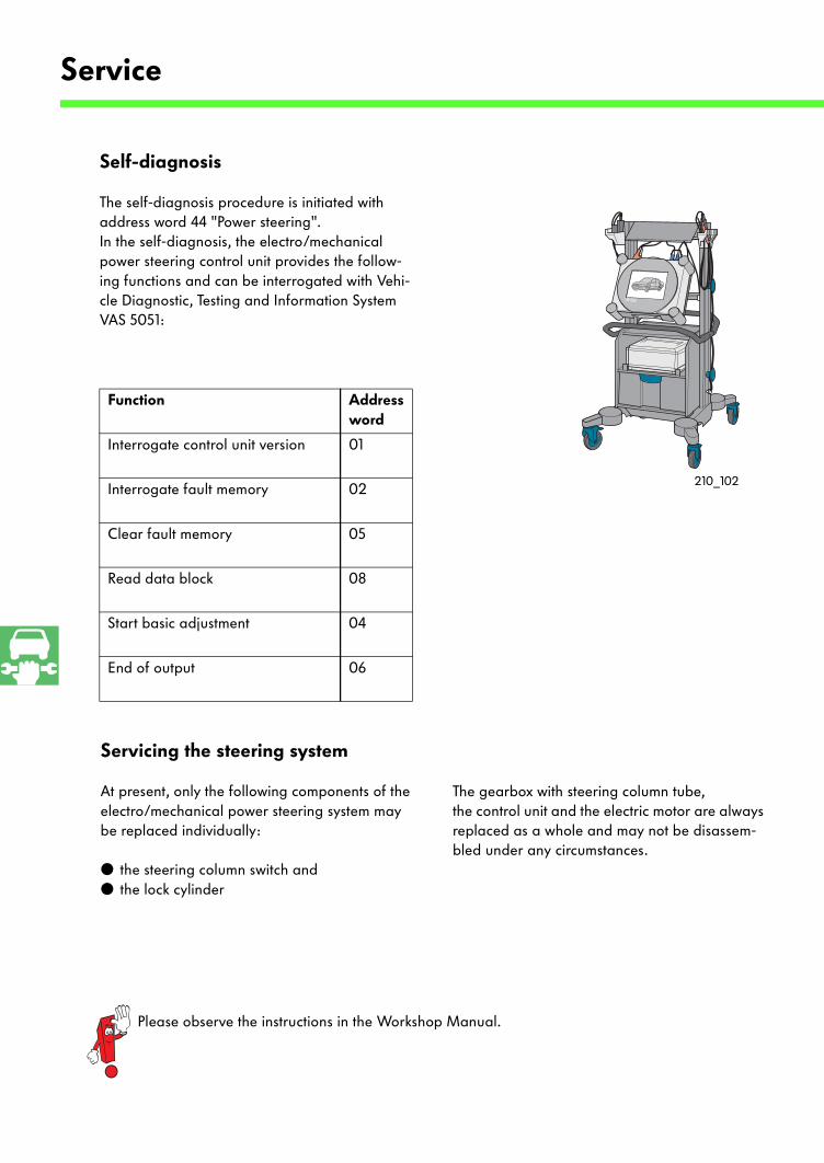
Self-diagnosis
The self-diagnosis procedure is initiated with address word 44 "Power steering". In the self-diagnosis, the electro/mechanical power steering control unit provides the follow-ing functions and can be interrogated with Vehi-cle Diagnostic, Testing and Information System VAS 5051:
Function Address word
Interrogate control unit version 01
Interrogate fault memory 02
Clear fault memory 05
Read data block 08
Start basic adjustment 04
End of output 06
Service
Servicing the steering system
At present, only the following components of the electro/mechanical power steering system may be replaced individually:
● the steering column switch and ● the lock cylinder
Please observe the instructions in the Workshop Manual.
The gearbox with steering column tube, the control unit and the electric motor are always replaced as a whole and may not be disassem-bled under any circumstances.
210_102
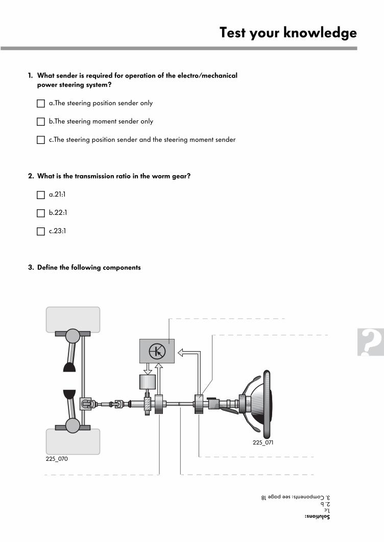
1. What sender is required for operation of the electro/mechanical power steering system?
a.The steering position sender only
b.The steering moment sender only
c.The steering position sender and the steering moment sender
2. What is the transmission ratio in the worm gear?
a.21:1
b.22:1
c.23:1
3. Define the following components
Test your knowledgeSolutions:1.c2. b3. Components: see page 18
225_071
225_070
For internal use only © VOLKSWAGEN AG, Wolfsburg
All rights reserved. Technical specifications subject to change without notice.
040.2810.44.20 Technical status: 1/00
❀ This paper is produced from
non-chlorine-bleached pulp.
225