Embed Size (px)
Citation preview
8/4/2019 The Engineering Design Revolution - CAD History - 02 Brief Overview
http://slidepdf.com/reader/full/the-engineering-design-revolution-cad-history-02-brief-overview 1/22
Chapter 2
A Brief Overview of the History of CAD
Author’s Note: The purpose of this chapter is to provide an overview of how theComputer-Aided Design (CAD) industry evolved without repeating any more thannecessary the material that appears in subsequent chapters.
Introduction
I have always been fascinated by old structures and machinery. Buildings such asthe Coliseum in Rome are all the more amazing when one realizes that two thousandyears ago builders had none of the construction equipment we take for granted today nordid they have any of the tools for creating designs that we now use. It was more of an artform than traditional engineering with the master builder directing the work of thousands.
Today, the Coliseum exhibits only part of its past glory. On the other hand, manyof the magnificent cathedrals and castles built in Europe during the Middle Ages still stand and many have been in continuous use every since they were first constructed.1 While we have many examples of early construction, few machines from that era stillexist. Most were war machines built to assault the enemy’s castles and were probablydestroyed in the process.
For centuries, engineering was focused on war, either building defensivefortifications or the machines to attack these fortifications. In fact the first non-militaryengineering discipline is called “civil” engineering to distinguish it from its militarycounterpart. Here also, few documents exist today describing how these early militarywar machines were built. Those that do exist were done on parchment or scratched intoclay tablets.
That is not to say that these early builders did not use sketches and drawings. Asan example, the Greek Parthenon could not have been constructed unless someonecarefully calculated the size and shape of each stone that went into the building. Mostlikely, some method was used to document that information since many people wereinvolved in the work. It was only during the early part of the 15th century that the conceptof graphic projections was well understood by early Italian architects. This was about thesame time that paper began to replace parchment as a drawing medium.
Existing engineering drawings describing machines and buildings date back to thefourteenth and fifteenth centuries. Most of these are in bound volumes stored in Europeanmuseums and libraries, particularly in southern Europe, and viewing them is restrictedprimarily to academic researchers. Today, we would describe them more as sketches than
as technical drawings. They were not to scale nor did they have dimensions. Many of these documents contain extensive textual descriptions that help one understand the intentof the drawings.
Early engineering drawings served two purposes. On one hand, they were areference experienced craftsmen used to build or construct what was portrayed. While thedrawings were more symbolic than what we are familiar with today, these craftsmen
1 Wilkinson, Philip, Amazing Buildings, Dorling Kindersley, New York, 1993
2-1 © 2008 David E. Weisberg
8/4/2019 The Engineering Design Revolution - CAD History - 02 Brief Overview
http://slidepdf.com/reader/full/the-engineering-design-revolution-cad-history-02-brief-overview 2/22
understood the intent of their iconic descriptions and were not concerned by the lack of dimensions since every machine or building they worked on was unique. The otherfunction of these drawings, particularly those collected in portfolios, was for presentationto the designer’s patron, either a prince or wealthy merchant.2
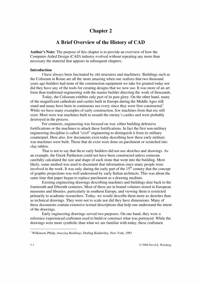
Some of the best known early engineering drawings is the work of Leonardo da
Vinci. While he is well known for his Mona Lisa, he was also a designer of militarymachines and forerunners of today’s industrial machines. Leonardo’s design work wasartistic in nature - more illustration than engineering drawings. No multi-view drawingsof any of his designs are known to exist today. Yet during the past century, skilledcraftsmen were able to construct models of many of his designs working strictly from hissketches.
Figure 2.1Leonardo da Vinci Machine for Cutting Files
“Both the drawing’s beauty and the ingeniousness of the mechanics make thisfile cutting machine very interesting. The operation is completely automatic: theweight falls unwinding the rope and activating both the rise and fall of the hammerand the progress of the piece to be cut, by using gears and levers. The completeautomation not only helps Man but also gives more homogeneous results,foreshadowing modern production processes.”3
2 Lefèvre, Wolfgang, Picturing Machines 1400-1700, MIT Press, 20043 Cianchi, Marco, Leonardo’s Machines, Edizioni Becocci – Largo Liverani, Florence, Italy
2-2 © 2008 David E. Weisberg
8/4/2019 The Engineering Design Revolution - CAD History - 02 Brief Overview
http://slidepdf.com/reader/full/the-engineering-design-revolution-cad-history-02-brief-overview 3/22
2-3 © 2008 David E. Weisberg
Early Drafting Practice
Most early practitioners of engineering drawings – such as Leonardo werealso artists. Gradually, a realization developed that drawings had to stand on theirown merits and that greater precision was needed. One early proponent of this
belief was Leon Battista Alberti who, in 1435 and 1436, wrote two works thatexplored the need to incorporate more Euclidian geometry in contemporarydrawings.4 He also proposed drawings with multiple views rather than the singleview then common.
Modern engineering design and drafting practice can probably be tracedback to the development of descriptive geometry, especially the work of RenéDescartes (1596–1650) and Gaspard Monge (1746–1818). Engineering drawingbegan to evolve more rapidly in the late 18
thcentury and picked up speed with the
Industrial Revolution of the 19th century.Peter Booker, in A History of Engineering Drawing, does a good job
distinguishing the more technical practices of the European continent from the craft
practices of England. He also describes in depth how early drafters (many of whomactually had degrees in engineering) used water color paints to highlight theirdrawings. This practice lasted until the early part of the 20 th century. What issomewhat surprising is the fact that drafting standards, as we know them today,were not taken seriously until after World War I. The first American standard in thisarea was not approved until 1935, just two years before I was born.5
It is my impression that a major catalyst in the development of technicaldrawing was the growth of the patent process. In order to receive a patent for a newdevice, one had to submit drawings in specific formats. This was complicated bythe fact that until the development of blueprints, no means existed to economicallycopy drawings and if multiple versions or copies of a drawing were needed they hadto be copied or traced by hand. Sir John Herschel discovered the blueprintingprocess in 1840 and introduced it in the United States in 1876 but it was much laterbefore it was widely used.
Early engineering drawings were often works of art. Like contemporarypenmanship, this is a skill that few retain. Permanent drawings were often madewith ink. An initial drawing was done using a pencil, T-square, triangles, scales,irregular (French) curves and drawing instruments such as compasses and dividers.Early drafting text books spent pages describing how to sharpen pencils and how tohold them to obtain an even line.
Once the pencil drawing was done, a sheet of tracing cloth would be tackedor taped over the original drawing. Each line would then be copied using pen andink. Particular attention was always paid to lettering on the drawing. Over the years,various templates and other devices were introduced that enabled drafters toproduce consistent quality lettering. Perhaps the most commonly used device wasthe Leroy Lettering Set manufactured by Keuffel & Esser. The set consisted of several templates of various sizes and a pen device that followed the shape of the
4 Lefèvre, Wolfgang, Picturing Machines 1400-1700, MIT Press, 2004, pg. 1765 Booker, Peter Jeffrey – A History of Engineering Drawing – Chatto & Windus 1963
8/4/2019 The Engineering Design Revolution - CAD History - 02 Brief Overview
http://slidepdf.com/reader/full/the-engineering-design-revolution-cad-history-02-brief-overview 4/22
2-4 © 2008 David E. Weisberg
letter in the template and reproduced that character in ink on the drawing. Thecompany sold a variety of templates with different fonts.
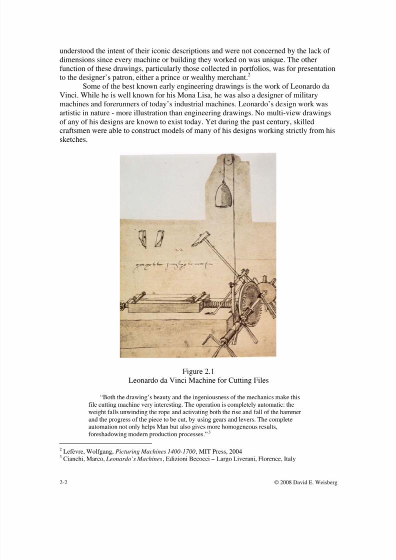
Another major advance was a device called a Universal Drafting Machine asshown in Figure 2.2. This device basically combined the T-square, triangles, scalesand protractor. It enabled the drafter to create perpendicular lines at any orientation.
Among the manufacturers were Universal Drafting Machine Company, Frederick Post, Bruning, and Keuffel & Esser. The latter two are of particular interest in thatthey subsequently attempted to develop CAD system businesses selling mid-pricedsystems. Both lettering templates and drafting machines are still sold todayalthough it may be hard to find a local dealer.
Figure 2.2Universal Drafting Machine
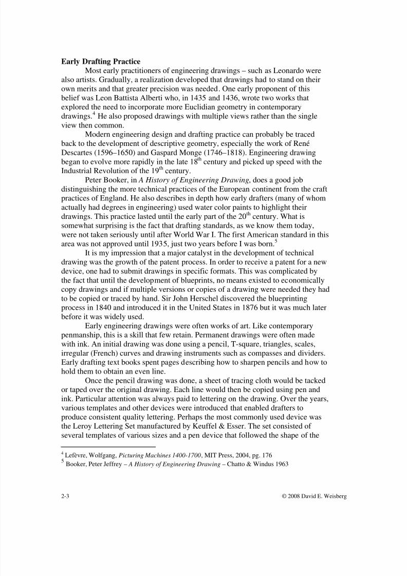
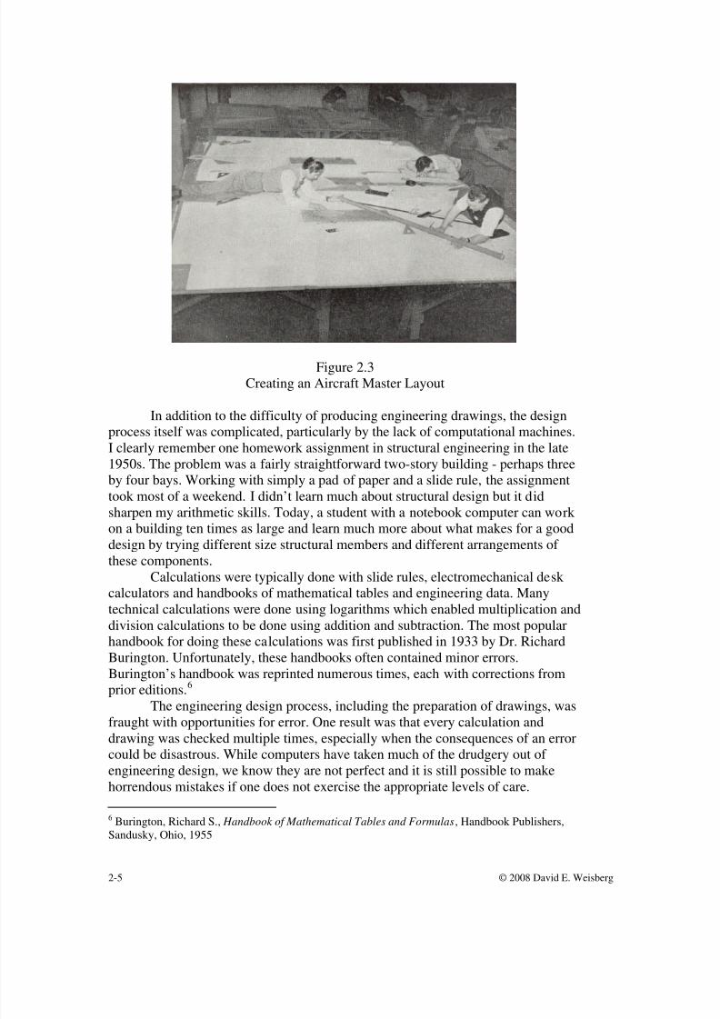
Eventually, different engineering disciplines developed their own methodsand approaches to engineering design and drafting. Architects had a style that wasapplicable to their work but was much different than what aeronautical engineersused. A major problem in the latter case was the need to produce accurate drawingsat 1:1 scale for large components of an airplane since it was not possible to convertsmaller drawings into the templates needed to produce these parts. Figure 2.3 showsseveral engineers and technicians creating a aircraft master layout.
During the decades following the Second World War, drafting equipment
suppliers introduced a variety of materials to improve the productivity of thedrafting process. Instead of drawing every detail on a drawing, stickers representingthese items could be applied to the drawing. Together with a new generation of reproduction machines, the time to create routine drawings was reducedsubstantially.
8/4/2019 The Engineering Design Revolution - CAD History - 02 Brief Overview
http://slidepdf.com/reader/full/the-engineering-design-revolution-cad-history-02-brief-overview 5/22
2-5 © 2008 David E. Weisberg
Figure 2.3Creating an Aircraft Master Layout
In addition to the difficulty of producing engineering drawings, the designprocess itself was complicated, particularly by the lack of computational machines.I clearly remember one homework assignment in structural engineering in the late1950s. The problem was a fairly straightforward two-story building - perhaps threeby four bays. Working with simply a pad of paper and a slide rule, the assignmenttook most of a weekend. I didn’t learn much about structural design but it didsharpen my arithmetic skills. Today, a student with a notebook computer can work
on a building ten times as large and learn much more about what makes for a gooddesign by trying different size structural members and different arrangements of these components.
Calculations were typically done with slide rules, electromechanical desk calculators and handbooks of mathematical tables and engineering data. Manytechnical calculations were done using logarithms which enabled multiplication anddivision calculations to be done using addition and subtraction. The most popularhandbook for doing these calculations was first published in 1933 by Dr. RichardBurington. Unfortunately, these handbooks often contained minor errors.Burington’s handbook was reprinted numerous times, each with corrections fromprior editions.6
The engineering design process, including the preparation of drawings, wasfraught with opportunities for error. One result was that every calculation anddrawing was checked multiple times, especially when the consequences of an errorcould be disastrous. While computers have taken much of the drudgery out of engineering design, we know they are not perfect and it is still possible to makehorrendous mistakes if one does not exercise the appropriate levels of care.
6 Burington, Richard S., Handbook of Mathematical Tables and Formulas, Handbook Publishers,Sandusky, Ohio, 1955
8/4/2019 The Engineering Design Revolution - CAD History - 02 Brief Overview
http://slidepdf.com/reader/full/the-engineering-design-revolution-cad-history-02-brief-overview 6/22
2-6 © 2008 David E. Weisberg
Understanding the technology food chain
There is a phenomenon that takes place in the computer industry that is thereverse of the biological food chain. Except in this case, rather than the larger animalseating successively smaller animals the lower levels of the technology food chain absorb
the capabilities of the higher levels. This phenomenon explains both the vastimprovements we see in performance coupled with steadily reduced costs, particularly inregards to hardware.
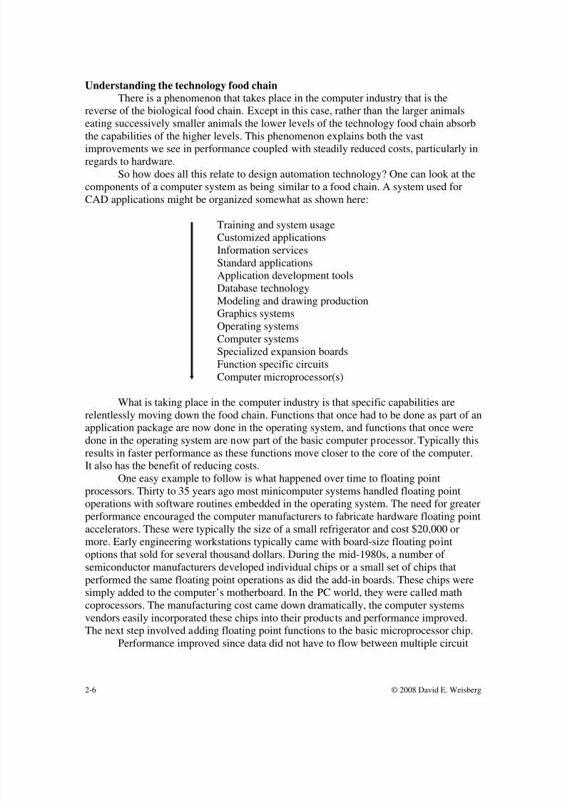
So how does all this relate to design automation technology? One can look at thecomponents of a computer system as being similar to a food chain. A system used forCAD applications might be organized somewhat as shown here:
Training and system usageCustomized applicationsInformation servicesStandard applications
Application development toolsDatabase technologyModeling and drawing productionGraphics systemsOperating systemsComputer systemsSpecialized expansion boardsFunction specific circuitsComputer microprocessor(s)
What is taking place in the computer industry is that specific capabilities arerelentlessly moving down the food chain. Functions that once had to be done as part of anapplication package are now done in the operating system, and functions that once weredone in the operating system are now part of the basic computer processor. Typically thisresults in faster performance as these functions move closer to the core of the computer.It also has the benefit of reducing costs.
One easy example to follow is what happened over time to floating pointprocessors. Thirty to 35 years ago most minicomputer systems handled floating pointoperations with software routines embedded in the operating system. The need for greaterperformance encouraged the computer manufacturers to fabricate hardware floating pointaccelerators. These were typically the size of a small refrigerator and cost $20,000 ormore. Early engineering workstations typically came with board-size floating pointoptions that sold for several thousand dollars. During the mid-1980s, a number of semiconductor manufacturers developed individual chips or a small set of chips thatperformed the same floating point operations as did the add-in boards. These chips weresimply added to the computer’s motherboard. In the PC world, they were called mathcoprocessors. The manufacturing cost came down dramatically, the computer systemsvendors easily incorporated these chips into their products and performance improved.The next step involved adding floating point functions to the basic microprocessor chip.
Performance improved since data did not have to flow between multiple circuit
8/4/2019 The Engineering Design Revolution - CAD History - 02 Brief Overview
http://slidepdf.com/reader/full/the-engineering-design-revolution-cad-history-02-brief-overview 7/22
2-7 © 2008 David E. Weisberg
boards or even between individual circuits. Floating point operations are virtuallytransparent to today’s computer systems and operating systems. In fact, most non-technical users are not even aware that this capability exists it has become so ubiquitous.
There are many other places in the technology food chain where functions havemoved from one level to a lower level. Graphic services software is a good example.
Graphic services are those functions that handle user interactions in a graphic system anddisplay requested images on the display screen. In the past, every CAD system vendorinvested a significant portion of its development resources producing software to handlethese functions. There were two reasons for doing this. First, standard software was notreadily available from the hardware vendors and second, this was how software vendorsattempted to discriminate their products from competitive products.
Over time, industry standards such as X-Windows, MOTIF, and Open GL becameaccepted in the market and workstation and PC vendors began offering this software aspart of their standard operating system. As a result, the vendors of application softwarerevised their development strategies. They began to use standard operating systemfunctions instead of proprietary software code for these tasks. Typically, 80 percent or
more of the earlier proprietary software was replaced through the use of standardtechniques incorporated in the operating system.There are many other examples that could be used to explain this concept
including graphic cards, networking, file management software and printer support. In theearly days of the CAD industry, system vendors had to spend considerable effortdesigning basic hardware components and programming foundation-level softwarefunctions. Today’s PC comes with all these capabilities built in and as a consequenceCAD software vendors are able to concentrate their development resources on providingenhanced and more reliable applications.
For many year, programmers spent considerable effort compensation for limitedmain memory, small data storage devices and slow performance. The changes since thefirst commercial system were introduced have been astounding. In 1972 vendors such asCalma agonized over the cost of increasing their systems main memory from 16KB to24KB. Disk drives were typically 5 to 20MB. And this had to be shared by typically fourusers. Today, you can buy a PC with 2GB of memory and a 250 GB disk drive for about$1,000. Companies that were successful were the ones that understood the pace thetechnology was changing and focused their R&D on what would be rather than what hadbeen.
As we will see in following chapters, many companies never did understand theseconcept or were simply incapable of adapting to the fast pace the underlying technologywas changing.
The computer begins to change engineering practice.
Chapters 3 and 4 provide a detailed description of some of the earlydevelopments involving computer graphics and research in applying computers todesign and manufacturing. It is not my intent to duplicate that information here.Rather, lets just try to put this pioneering work in perspective.
Early computer development in the mid-1940s was mostly funded bymilitary agencies and these machines were used to calculate information such asballistic trajectory tables. In fact the term “computer” was originally used to
8/4/2019 The Engineering Design Revolution - CAD History - 02 Brief Overview
http://slidepdf.com/reader/full/the-engineering-design-revolution-cad-history-02-brief-overview 8/22
2-8 © 2008 David E. Weisberg
describe the people who did these calculations manually. A decade later, IBM,Sperry-Rand and a few other companies began delivering computers to largeengineering organizations, especially in the defense and automotive industries.Gradually, a number of programs for solving engineering problems were developed.In some disciplines, such as highway design, programs were readily shared between
users while in other areas they were treated as highly proprietary.The typical process for solving a technical problem involved the engineerfilling out a coding form with applicable data. These forms would then be given to akeypunch operator who would produce a deck of punch cards and perhaps a listingof the data. The engineer would then review the numerical listing for errors andhave the keypunch operator make corrections if necessary. The card deck wouldthen be submitted to a computer operations scheduler who would submit the job tobe executed.
These computers ran one job after another in what was referred to as a batchoperation. The results of the computer run would then be provided to the engineerin the form of a numerical listing. Frequently, this meant that someone had to
carefully plot the results in a way that enabled them to be visually interpreted. Theoverall process was referred to as a “closed shop” and it could take anywhere froma day for a minor problem to several weeks for a complex problem.
Lower cost computers that could be operated directly by engineeringdepartments began to appear in the mid 1950s. Machines such as the LibrascopeLGP-30 (Librascope General Purpose) were vacuum tube machines that wereslower than today’s hand-held calculators but still provided a substantial advanceover manual calculations. Output was mostly in the form of numerical listingsalthough digital plotters from CalComp Computer Products began appearing around1960.
IBM introduced the very popular 1620, an all-solid-state computer, in 1960.This machine leased for about $3,000 per month (most IBM computer were leasedrather than sold outright at the time) and had performance of less than 0.01 MIPS(Millions of Instructions Per Second). While this is incredibly slow by today’sstandards, it was more than adequate for solving many engineering problems.
Large mainframes such as the IBM System 360 Model 60 leased for$40,000 per month and had performance of about 0.36 MIPS. These computerssupported double precision floating point arithmetic and therefore were used formore complex engineering analysis applications.
Development of in-house CAD systems
In the mid-1960 time frame there were no commercial graphics systems onthe market except for the Control Data Digigraphics system described in Chapter 6and only a few of these were sold. The need for computer-based graphic systems toimprove the productivity of engineers and drafters was slowly being recognized bylarge manufacturing companies, especially those in the automotive and defense andaerospace industries. Some of the work undertaken by these companies is describedin Chapters 3 and 4.
This early work fell into two categories. On one hand, automotivecompanies such as Renault and Ford focused on the mathematical definition of
8/4/2019 The Engineering Design Revolution - CAD History - 02 Brief Overview
http://slidepdf.com/reader/full/the-engineering-design-revolution-cad-history-02-brief-overview 9/22
2-9 © 2008 David E. Weisberg
complex surfaces while other companies, such as Lockheed California focused onimproving drafting productivity. The Renault work eventually evolved intoDassault Systèmes’s CATIA while Ford’s PDGS software is probably still used onoccasion today. Lockheed’s work, of course, resulted in the CADAM productdescribed in Chapter 13.
What was common to this in-house activity was that these companies usedlarge mainframe computers, primarily those produced by IBM, and they mostlyused vector refresh graphics terminals. A key hardware development was theintroduction of the IBM System 360 product line in April 1964 which included theModel 2250 refresh graphics terminal. In subsequent years a number of companiesincluding Adage and Spectragraphics produced terminals that were “plugcompatible” with IBM’s equipment, but typically less expensive. Other thanCADAM and CATIA, little of this in-house work led directly to successfulcommercial systems.
Introduction of commercial systems
The CAD industry, as it subsequently evolved, started in 1969 with theformation of Applicon and Computervision. They were joined within a few years byAuto-trol Technology, Calma and M&S Computing (Intergraph). These companiesand other early industry pioneers are described in later chapters.
While the in-house systems mentioned above used mostly mainframecomputers and vector refresh graphics terminals, the early commercial systems usedminicomputers such as the Digital Equipment PDP-11 and the Data General Nova-1200 and Tektronix storage tube displays. The typical system consisted of a 16-bitminicomputer with an 8KB or 16KB main memory, a 10MB or 20MB disk driveand one to four terminals. Most systems included large digitizer tables, keyboardsfor command entry, a tablet for coordinate entry and a digital plotter. The primarymanufacturers of plotters at the time were CalComp, Gerber and Xynetics.
The typical system included a considerable amount of proprietary hardware.For the most part, these companies were equipment manufacturers who developedsoftware to help sell their hardware. Fifteen years later most were struggling tomake the transition to a software business model where industry-standard computerhardware was being used. Early systems were predominately two-dimensionaldrafting oriented with a particular focus on integrated circuit and printed circuitboard layout. In the latter case, artwork was often generated on photoplottersproduced by Gerber Systems.
A typical single station system sold for about $150,000 in 1972 withadditional stations costing perhaps $50,000 each. This is equivalent to about$700,000 and $230,000 respectively 25 years later. Domestically, all thesecompanies sold their systems through a direct sales organization. With just a fewexceptions, the sales people were all men. Internationally, country distributors wereutilized.
These systems were marketed predominately on the basis that they couldreduce current operating costs. If you had a drafting department with 20 drafters,buy one of these systems, run it around the clock and you could get the sameamount of work done with perhaps 10 or 12 people. In some cases, productivity
8/4/2019 The Engineering Design Revolution - CAD History - 02 Brief Overview
http://slidepdf.com/reader/full/the-engineering-design-revolution-cad-history-02-brief-overview 10/22
2-10 © 2008 David E. Weisberg
improvements were truly spectacular, especially within organizations that did a lotof repetitive work. Most of these early systems had user-centric programminglanguages that facilitated the development of automated processes for generatingstandardized drawing working off minimal input data.
Performance was often an issue and early manufacturers put significant
effort into building graphic interfaces that would speed up the process of generatingdisplay images. When a graphical element was moved or deleted from a storagetube display, the entire image had to be regenerated. Adequate performancerequired imaginative software and specialized hardware.
Throughout the 1970s, the CAD industry grew from virtually zero to abillion dollar hardware and software business. New companies constantly joined thefray but the market was dominated by the five turnkey vendors mention earlier.
Evolution of geometrics modeling
One area where university research played a significant role in the evolutionof the CAD industry was in geometric modeling, both in regards to surface
geometry and solids modeling. The earliest CAD systems simply handled two-dimensional data, emulating traditional drafting practices. The initial transition tothree dimensions was done using wireframe geometry – points in space and thelines connecting these points.
Solid objects and surfaces were defined simply by lines that represented theedges of the geometry. Without additional information, it was not possible togenerate shaded images of wireframe objects nor could hidden lines be removedwithout manual intervention. Obviously, better methods were needed.
Surface modeling technology was driven by the automotive and aircraftindustries since manually defining and manufacturing sheet metal parts for thesevehicles was becoming increasingly time-consuming and costly. One just needs tocompare the boxy Ford Model A of 1930 to the 1975 Chevrolet Nova to see howthe automotive industry was changing. Likewise, new jet aircraft required smoothcontours to reduce drag.
Sheet metal parts were manually designed using cross-section drawingsfrom which templates were made. These were then used by patternmakers toproduce a wood pattern that subsequently was used to machine stamping dies with amilling machine that copied the pattern. Many different people were involved in theprocess which was susceptible to error at each step. By the early 1960s, NCmachine tools were becoming more commonplace and a way was needed toeconomically generate the digital information to drive these devices.
One of the first techniques for mathematically describing surfaces, known asCoons patches, was developed by Steven Coons at MIT in the mid-1960s.7 Anothermajor center of surface definition research activity was in France. As early as 1958,Paul de Casteljau, working at Citroën, developed a mathematical approach fordefining surfaces. Due to a perceived competitive advantage, Citroën did not
7 Coons, Steven, Project MAC-TR-41, MIT 1967
8/4/2019 The Engineering Design Revolution - CAD History - 02 Brief Overview
http://slidepdf.com/reader/full/the-engineering-design-revolution-cad-history-02-brief-overview 11/22
2-11 © 2008 David E. Weisberg
disclose his work until 1974. By then, a number of academic and industrialresearchers had moved on to implement other techniques.8
Around 1960, Pierre Bézier proposed to Renault’s management that thecompany develop a method for mathematically defining automobile surfaces. By1965 this work was well underway and by 1972, Renault was creating digital
models and using the data to drive milling machines. The company called thesystem UNISURF and it eventually became an important component of DassaultSystèmes CATIA software (See Chapter 13). A key aspect of the work was thedevelopment of the well known Bézier curves and surfaces which are still used inmany graphics applications. Bézier based his work, in part, on the earlierdevelopment of the Bernstein polynomials, introduced in 1911 by Sergi Bernstein.
The work of Rich Riesenfeld, Elaine Cohen, Robin Forest, Charles Lang,Ken Versprille and others led to the introduction of a number of other ways fordefining curves and surfaces. The sequence of events went somewhat as follows.Coons was working with Ivan Sutherland (See Chapter 3) who had gatheredtogether a group of very good mathematicians and programmers including Bob
Sproul, Danny Cohen, Larry Roberts, and Ted Lee. At times it is somewhatconfusing as to what went on at MIT and what work was done at HarvardUniversity but suffice it to say that this group was instrumental in developing someof the early theory in the area of geometric modeling.
They were soon joined by Robin Forrest who was a graduate student in theMathematical Laboratory at Cambridge University. During the summer of 1967,Coons and Forrest developed a technique for defining rational cubic forms. Thiswas followed in 1969 by Forrest’s Ph.D. thesis in which he defined methods fordescribing different graphic entities using the rational cubic form methodology.
A year later, Lee’s Ph.D. work at Harvard extended Forrest’s research todescribe bicubic surface patches. Coons moved to Syracuse University in 1969where he became Rich Risenfeld’s Ph.D. thesis advisor. Risenfeld’s described anew approach called B-splines in 1973.9 (The term B-spline is derived from theterm Basis Spline of which the Bernstein Basis is a special case.) During the 1970s,there was a constant flow of individuals between Syracuse, New York andCambridge, Massachusetts. Eventually, the University of Utah became a player inthis story when some of the Harvard and Syracuse people joined David Evans andIvan Sutherland to focus on graphics applications.
Another Syracuse Ph.D. candidate at the time was Ken Versprille who wasworking on the definition of rational B-splines. He completed his Ph.D. thesis onthe subject in 1975 prior to joining Computervision.10 Versprille is credited bymany people as being the developer of NURBS (Non-Uniform Rational B-Splines).
8 Bézier, Pierre – A View of the CAD/CAM Development Period – Annals of the History of
Computing Volume 20, Number 2, 19989 Risenfeld, Rich Applications of B-Spline Approximation to Geometric Problems of CAD, Ph.D. thesis,Syracuse University, February 197310 Versprille, Kenneth J., Computer-Aided Design Applications of the Rational B-Spline Approximation
Form, Ph.D. thesis, Syracuse University, February 1975
8/4/2019 The Engineering Design Revolution - CAD History - 02 Brief Overview
http://slidepdf.com/reader/full/the-engineering-design-revolution-cad-history-02-brief-overview 12/22
2-12 © 2008 David E. Weisberg
The next step at Syracuse was the work done by Lewis Knapp whose 1979 Ph.D.thesis was also a key building block in the evolution of NURBS. 11
An additional step was the development of what became known as the OsloAlgorithms. In early 1979, Riesenfeld and his wife, Elaine Cohen, took a sabbaticalfrom Utah to work with the CAD Group at the Central Institute, a research activity
associated with the University of Oslo. Together with Tom Lyche, they defined aset of mathematical techniques that substantially enhanced the functionality of B-splines.
Significant work on surface definition techniques was also being done at anumber of aircraft and automotive companies. Boeing was particularly active in thelate 1970s and early 1980s working on surface geometry techniques based on thisearlier academic research. One of the key developments at Boeing was the work James Ferguson did with cubic curves and bicubic surface patches.
12Boeing was
also one of the early proponents of IGES (Initial Graphics Exchange Specification)based on CAD system interoperability efforts it had underway at the time. In 1981,Boeing proposed that NURBS be added to IGES. This subsequently occurred in
1983.
13
The development of NURBS technology has proven to be one of the keybuilding blocks for advanced geometric modeling. As David Rogers, a professor atthe United States Naval Academy, so eloquently puts it:
“…with NURBS a modeling system can use a single internalrepresentation of a wide range of curves and surfaces, from straightlines and flat planes to precise circles and spheres as well asintricate piecewise sculptured surfaces. Furthermore, NURBSallow these elements to easily be buried within a more generalsculptured surface. This single characteristic of NURBS is key todeveloping a robust modeling system, be it for computer aideddesign of automobiles, aircraft, ships, shoes, shower shampoobottles, etc. or for an animated character in the latest Hollywoodproduction …….”
14
A key observation needs to be made at this point. Much of the work goingon in developing better surface definition techniques was being done at academicresearch centers and was typically published in widely available journals. Eachresearcher was, therefore, able to build on the work of those who had tackled earlieraspects of the problem. As seen by what occurred at Citroën, this would probablynot have occurred if the work had primarily been done by industrial companies.
In regards to this latter issue, most automotive manufacturers were alsoworking on internal surface geometry applications. Their major focus was in taking
11 Knapp, Lewis, A Design Scheme Using Coons Surfaces With Nonuniform Basis B-Spline Curves, Ph.D.thesis, Syracuse University, February 197912 Ferguson, James C. Multi-variable curve interpolation, Journal of the ACM, Vol. 11, No. 2, 1964, Pg.221-228 13 Rogers, David F., An Introduction to NURBS, Academic Press, San Diego, 2001, Pg. 13014 Ibid, Preface
8/4/2019 The Engineering Design Revolution - CAD History - 02 Brief Overview
http://slidepdf.com/reader/full/the-engineering-design-revolution-cad-history-02-brief-overview 13/22
2-13 © 2008 David E. Weisberg
data points from full scale clay models and converting that information into digitalsurfaces that could be used to machine stamping dies.
Moving from wireframe and surface geometry to solids modeling
This subject could easily be a book in its own right and, in fact, a number of
books on solids modeling have been written in recent years. Unfortunately most arefilled with complex equations and diagrams that only a mathematician wouldappreciate. My intent is to try to put the evolution of solids modeling into morereadable terms. It is interesting to note that there was little overlap between theindividuals working on surface definition technology and the early proponents of solids modeling
There were a number of different research threads that eventually led to today’ssolid modeling technology.
15One of the most important of these revolves around the
activities of The CAD Group in Cambridge, England. Starting in the late 1960’s, theefforts of this organization resulted in what is probably one of the more influential seriesof innovations and developments in the CAD industry. Basically, The CAD Group
created the foundation for the three-dimensional solids modeling software that has beenused as a technical building block by hundreds of CAD software companies and is usedby millions of users worldwide today.
Determining where three-dimensional solid modeling started has proved almostimpossible. Solid modeling research started in at least eight geographic locationsindependently of each other, almost all at the same time in the late 1960s and early 1970s.Even with activity and research being conducted around the world, no real usable productwas available until the late 1970s and it really wasn’t until the late 1980s that solidsmodeling became a commercial reality. However, many consider the first commercialproduct to be MAGI’s SynthaVision which used primitive solids with high resolutionrendering. Launched in 1972, SynthaVision is famous for its use in Walt DisneyProductions’ 1982 movie TRON , the first full-length animated feature film.
It was at the PROLAMAT Conference, held in Prague in 1973, that many of geographically disparate groups initially met – and started talking about this technology.At this conference, Ian Braid, from Cambridge’s CAD Center, presented BUILD – usingwhat is now called B-Rep or Boundary Representation technology. At the same event,Professor N. Ok ino from Hokkaido University, introduced TIPS-1, a CSG-based solidmodel program.16 Also in attendance were Herbert Voelcker from the University of Rochester who was managing the PADL research activity, Professor Spur who wasconducting research into solids modeling at the University of West Berlin, Dr. J. M Brun from University of Grenoble who masterminded Euclid (See Matra Datavision in Chapter21) and others who helped drive the proliferation of solids modeling in following years.
The CAD Group at Cambridge was involved in this work far longer than anyother organization. They developed technologies in the 1970s that are still being used(albeit using newer state-of-the-art programming techniques) today. ACIS (See SpatialTechnology in Chapter 21), subsequently developed by this team, is currently used in
15 Particular thanks go to Rachael Taggart for help with this section as well as input from Charles Lang.16 CSG or Constructive Solid Geometry builds a solid model using primitive shapes such as cones andspheres and Boolean combinations of these basic elements. Boundary Representation of B-Rep models usesurface definitions to describe the enclosed solid.
8/4/2019 The Engineering Design Revolution - CAD History - 02 Brief Overview
http://slidepdf.com/reader/full/the-engineering-design-revolution-cad-history-02-brief-overview 14/22
2-14 © 2008 David E. Weisberg
several million CAD seats. The same group also pioneered what became Parasolid, whichsupports another million or so CAD seats worldwide. None of the other solids modelingpioneers can boast of this type of track record.
Charles Lang graduated from Cambridge University in 1960 with a degree inengineering. After several years at Mullard Research in England, Lang enrolled as a
graduate student at MIT in 1963 and worked at Project MAC for more than 18 monthswith Doug Ross and Steven Coons. Lang was then recruited back to CambridgeUniversity’s Computer laboratory by Professor Maurice Wilkes.
The British Government arranged funds and resources that underwrote theactivities of the Cambridge CAD Group in 1965 – the group founded by Wilkes andheaded by Lang until 1975. In 1969, the group started developing solid modelingsoftware on a Digital PDP-7 system using assembly language programming.“Unfortunately no one told us it was impossible,” says Lang. “But then Ian Braid turnedup.”17
In 1970, Ian Braid joined the group and focused on writing solid modeling codewith particular attention to data structures. The result of his first thesis was BUILD1 – a
solid modeling system presented at PROLOMAT – that used Boolean logic and simplesolid geometry, grey-scale images and hidden line drawings. “BUILD1 had only planarand cylindrical surfaces implemented incompletely,” according to Braid. “But it showedhow one might interact with a solid model held in a computer and what could be donewith it in changing or recording models, generating pictures, finding mass properties or ingenerating cutter paths.”
Alan Grayer joined the team in the early 1970s, and by 1975 was generating NCtapes for 2½ axis milling machines. “This was the first time anybody automaticallygenerated NC from a 3D model,” says Lang. The Cambridge team regularly worked withPierre Bézier at Renault as well as maintaining close relationships with MIT, Utah andSyracuse researchers.
According to Lang, funding for the Cambridge CAD Group started lookinguncertain in 1974, and the team formed a company called Shape Data. Founders were IanBraid, Alan Grayer, Peter Veenman and Charles Lang. “The company started withoutmoney and indeed, we never really formed it to make money,” says Lang. “We started itto make the technology work.” Shape Data was the first spin-off from the CambridgeCAD Group and according to Lang there have been nearly 90 spin-offs from thecomputer labs since. Peter Veenman started with the company full-time although the restof the team remained with the CAD Group until 1980.
“Our original vision for Shape Data was based on a great relationship with DaveEvans – he knew modeling was much more fundamental than graphics and he had avision of Evans & Sutherland being a one stop shop for people to get components to build3D systems,” Says Lang.
In 1978, Shape Data completed the industry’s first commercial release of a solidmodeling kernel – called Romulus. In 1980, Lang, Braid and Grayer joined Shape Datafull-time. Then, in 1981 the company and its technology was acquired by Evans &Sutherland. In 1985, Lang, Braid and Grayer left the company and formed Three-Space
17 Quotes from Lang and Braid are based on telephone conversations and emails in mid-2004 with theauthor and Rachel Taggart.
8/4/2019 The Engineering Design Revolution - CAD History - 02 Brief Overview
http://slidepdf.com/reader/full/the-engineering-design-revolution-cad-history-02-brief-overview 15/22
2-15 © 2008 David E. Weisberg
Limited without a particularly clear idea of what they would do. Within several years, theteam was hard at work on a new solids modeler – ACIS.
Simultaneously, Shape Data began work on creating Parasolid – a solid modelingkernel that was derived from the original Romulus work but used newer techniques andtechnologies.
As described in Chapter 21, Spatial Technology funded the early development of ACIS which was initially released in 1988. That same year Shape Data releasedParasolid, and the company was acquired by McDonnell Douglas. In 1989, Parasolid wasfirst used in a release of McDonnell Douglas’ Unigraphics software.
Another significant center of solids modeling development was the ProductionAutomation Project (PAP) at the University of Rochester. PAP was founded in 1972 byHerbert Voelcker who was a professor of electrical engineering at the time. 18 The intentwas to develop automatic programming systems for NC machine tools. Voelcker was joined by Ari Requicha in 1973. The group soon redirected its activity to solids modelingand its first system, PADL-1 (Part & Assembly Description Language) was demonstratedat a CAM-I meeting in 1976 and made publicly available 15 months later. This was
followed in 1981 by PADL-2. In addition to the normal contingent of graduate andundergraduate students, PAP also benefited from the assignment of engineers on loanfrom industrial companies that were interested in understanding this new technology.
The initial PADL-1 software used a combination of CSG and B-Rep techniques.The software was written in a derivative of FORTRAN and therefore was able to beported between computer system fairly easily. The University of Rochester licensed thesoftware in source code format for $1,200 to universities and $2,400 to commercial users.Licensees had virtually unlimited rights to the software. Between 1978 and 1985, theuniversity issued 80 licenses. Fifteen years later, PADL-1 was still being used inacademic institutions as a teaching tool. The PADL-2 project was launched in early 1979with Chris Brown as the project director. Approximately $800,000 in funding wasprovided by ten industrial sponsors and the National Science Foundation. The intent wasto be able to model 90 to 95 percent of unsculptured industrial parts. PADL-2 was alsowritten in FORTRAN for portability reasons although this restricted the developmentteam’s ability to fully utilize newly evolving object-oriented programming techniques.
PADL-2 was initially distributed to the project sponsors in mid-1981. Whileorganizations such as Sandia National Laboratory and Kodak used the softwareextensively for internal applications, most of the industrial sponsors did little with thesoftware. An exception was McDonnell Douglas Automation which began thedevelopment of UNISOLIDS based on PADL-2 in 1981 and demonstrated the software atAUTOFACT in late 1982. Public distribution of PADL-2 began in mid-1982. Licensefees without the rights to redistribute the software varied from $600 for educationalinstitutions to $20,000 for commercial concerns. Companies that wanted to buildcommercial solutions around PADL-2 were charged $50,000, the same amount paid bythe initial sponsors. Between 1982 and 1987, Rochester issued 143 license agreements.
In 1987, the PAP was disbanded and the PADL technology and Voelcker movedto Cornell University which continued to distribute the software for a period of time. One
18 Voelcher, Herbert B. and Requicha, Aristides A. G., Research in Solid Modeling at the University of
Rochester: 1972-87 , chapter in Fundamental Developments of Computer-Aided Geometric Modeling,Edited by Les Piegel, Academic Press, San Diego, 1993
8/4/2019 The Engineering Design Revolution - CAD History - 02 Brief Overview
http://slidepdf.com/reader/full/the-engineering-design-revolution-cad-history-02-brief-overview 16/22
2-16 © 2008 David E. Weisberg
interesting development involved Cadetron which recoded PADL-2 in C for use on PCs.Cadetron was subsequently acquired by Autodesk where the software was marketed asAutoSolid.
The basic structure of the CAD industry changes
The decade of the 1980s was perhaps the most significant period regarding theevolution of the CAD industry. At the start of the decade, the industry was dominated byfive companies – Applicon, Auto-trol Technology, Calma, Computervision and M&SComputing (Intergraph). Other companies starting to make themselves felt includedMcDonnell Douglas Automation, SDRC and IBM which was marketing Lockheed’sCADAM software. Only Computervision and IBM manufactured their own computersbut the other companies, except for SDRC, designed and built relatively expensivegraphics terminals and other system components. For the most part, these turnkeysystems vendors were manufacturing companies that happened to sell software. Theindustry’s early profitability clearly revolved around manufacturing margins.
Two significant changes took place in the early 1980s. One was the transition
from 16-bit minicomputers such as the Digital PDP-11 and Data General Nova 1200 to32-bit super-minicomputers such as the Digital VAX 11/780. At the time, Digital clearlydominated this segment of the computer market. The other change taking place was theshift from Tektronix storage tube graphics terminals to color raster technology. In thelatter case, this actually enabled the companies to manufacture a greater portion of theirsystems. All of the companies were engaged in major revisions to their software – insome cases a total rewrite of these systems.
In general, CAD systems circa 1980 sold for about $125,000 per seat or theequivalent to over $300,000 today. That was a lot of money when you realize that youcan purchase Autodesk’s Inventor Professional software and a moderately highperformance PC for less than $10,000 today. Early systems often required an air-conditioned computer room. Even basic operator training took several weeks and, formost systems, it could easily be six months before they were back to a 1:1 productivityratio.
Because these systems were relatively expensive they tended to be run on what istypically referred to as a “closed shop” basis. The systems were typically operated byindividuals who spent full time working at the graphics consoles. Engineers anddesigners would bring work to the “CAD Department” and then come back hours or dayslater to received plotted output which they would carefully check. Marked up drawingswould be returned to the CAD operators who would revise the drawings and return themonce again to the requestor. It was a rare situation where an engineer was either allowedto use a system for interactive creative design work or sit with an operator and have thatperson directly respond to suggestions. The costly nature of these systems often resultedtwo, or even three shift, operation.
A snapshot look at the industry
In late 1982, Input, a market research firm then headquartered in Mountain View,California, prepared an in-depth analysis of the CAD industry for General Motors. Thisreport was based on extensive interviews with both users and vendors. While I do not
8/4/2019 The Engineering Design Revolution - CAD History - 02 Brief Overview
http://slidepdf.com/reader/full/the-engineering-design-revolution-cad-history-02-brief-overview 17/22
2-17 © 2008 David E. Weisberg
agree with all their findings, the report did highlight some key issues facing the industryand the user community at that time.
The lack of effective solids modeling was identified as a major constraint onindustry growth. Enough research on the subject had been done by then to whet theappetite of users but workable solutions were still off in the future. The report also
emphasized application integration or rather, the then current lack of solutions thatintegrated a variety of design and manufacturing applications. The need to tie databasemanagement tools into the application mix was also an urgent requirement. Usersparticularly wanted more reliable software. These three issues were felt by respondents tobe more important than ease of use and adequate service and education.
Key trends then underway included the transition to intelligent workstations,networking and the shift to color graphics. The need for color was reported to be a muchhigher priority in late 1982 than it had been in a similar study the firm did just a yearearlier. The report also identified a major shift in costs that was already underway –hardware was becoming less expensive and software was becoming more costly. Input’sreport did not spend much time discussing the stress this would put on current turnkey
system vendors.A portion of the report touched on the subject of user productivity. The authorspointed out that most companies were justifying the technology simply on draftingproductivity and were not taking into consideration other elements of productivityincluding shorter product cycles and improved product quality. The inability of mostvendors to expound on this issue was considered a drag on market acceptance of CADtechnology.19
Engineering workstations replace minicomputers
One of the most significant hardware development in the 1980s was theintroduction of the engineering workstation. Most CAD system vendors had beenimplementing more and more capability in their graphic terminals, offloading anincreasing portion of graphic manipulation functions from the host computer. Theengineering workstation took this one step farther and offloaded all application softwareexecution as well. The minicomputer or mainframe host was now needed just for filemanagement if at all and this was soon replaced by a specialized form the workstationcalled a server. The other key characteristic of these devices was that they could benetworked together so that they could share data and even computer programs.
The first engineering workstation vendor was Apollo Computer, started by John(Bill) Puduska. The company’s early machines were more oriented towards softwaredevelopment but shortly after signing OEM customers such as Auto-trol and Calma aswell as Mentor Graphics, a leading EDA vendor, Apollo began producing systems withgood graphics capabilities. These early machines used Motorola 68000 microprocessorsand their floating-point accelerators were reduced in size to just a single circuit board.
There were a number of advantages to workstation based CAD systems over theolder minicomputer based products. First of all, the entry cost and the per seat cost wasmuch lower. Prices quickly dropped to about $75,000 per seat and within a few years tounder $50,000. In addition, performance was more predicable. When a company had six
19 Overview of the Computer-Aided Design and Manufacturing Engineering Marketplace, Input, MountainView, California, November 1982
8/4/2019 The Engineering Design Revolution - CAD History - 02 Brief Overview
http://slidepdf.com/reader/full/the-engineering-design-revolution-cad-history-02-brief-overview 18/22
2-18 © 2008 David E. Weisberg
or eight terminals hung off a VAX 11/780 and one user initiated a complex analysis task,the performance of all the other terminals suffered. If the host computer failed, all theterminals were inoperative. With engineering workstations, performance depended uponwhat the specific user did, not other operators, and if one workstation failed, the otherswere still operable.
Apollo’s workstations incorporated a significant amount of proprietarytechnology, particularly in regards to its operating system and networking. The AEGISoperating system was UNIX-like but it was not UNIX. The token-ring network wasproven technology but it was not Ethernet which was rapidly emerging as a computerindustry standard. Sun Microsystems was started just enough later than Apollo that it wasable to use industry-standard UNIX software and Ethernet components. Sun was soon joined by Silicon Graphics or SGI as most people know it. SGI emphasized high-performance graphics but otherwise produced relatively standard workstations andservers.
Soon, the computer industry exploded with perhaps 20 or more manufacturers of engineering workstations. They were often referred to as JAWS (Just Another
Workstation System). Most never really got off the ground and soon faded from sight.The major computer manufacturers were a different story. Companies such as IBM,Hewlett-Packard and Digital realized that these workstations were a competitive threatand they introduced similar products. IBM’s RS/6000 was a respectable product but HPand Digital struggled to gain momentum in this area. Digital never really establishedsignificant market share. HP solved its problem by acquiring Apollo in 1989.
As described in later chapters, the early industry leaders struggled in making thetransition to industry standard workstation hardware and becoming more of software andservices businesses. The fundamental problem was that they each had made significantinvestments in manufacturing facilities and personnel and now were faced with theproblem of unwinding that business. This was not easy. Some like Auto-trol tried tomaintain a manufacturing focus by repackaging its Apollo workstations in the sameterminal configurations it had used earlier. There was no easy way out and it led to theeventual downfall of all the early leaders except Intergraph.
Meanwhile a new group of vendors gained significant market share. Key amongthem was IBM teamed up initially with Lockheed’s CADAM Inc. and later with DassaultSystèmes, McDonnell Douglas Automation which eventually morphed into UGS, SDRCand two newcomers, Autodesk and Parametric Technology, both of which are describedbelow.
As the price of CAD systems came down, changes in how they were used alsobegan to occur. While many organizations continued to operate CAD departments, otherbegan to disperse systems into their design and manufacturing organizations. Instead of providing sketches to a professional CAD operator, design engineers were trained to dothis work themselves. This became increasingly significant as new versions of thesoftware enabled users to create drawings as a byproduct of the design process. The basicorganizational structure of design teams began to change as companies adapted to thequickly evolving technology.
The personal computer becomes the new wild card
8/4/2019 The Engineering Design Revolution - CAD History - 02 Brief Overview
http://slidepdf.com/reader/full/the-engineering-design-revolution-cad-history-02-brief-overview 19/22
2-19 © 2008 David E. Weisberg
By 1987, vendors of traditional CAD systems had sold about 100,000 seats of software and the equipment to support these users. It had taken them 17 years to do so. In just five years, the new PC software vendors installed a like number of seats.
20Today
there are literally millions of CAD users, the vast majority working at PCs.Personal computers actually predate the engineering workstation described above.
The early machines were more collections of components for the computer hobbyist thanserious technical tools. This began to change in August 1981 when IBM introduced itsfirst PC, the Model 5150, which came with 16KB of memory, an alphanumeric displayand no hard disk drive. But it only cost $1,995. The key decisions on the part of IBMwere to use an Intel microprocessor, a 4.7 MHz 8088, and a new operating system from asmall company in Seattle, Microsoft. As the familiar line goes – the rest is history.
It took some time before IBM PC-compatible machines had the performance andgraphics capability to handle CAD software. Initially, the few companies such as T&WSystems (see Chapter 20) that were providing PC software worked with similarly pricedcomputers such as the Apple II or more expensive machines such as Terak 8510. Therewere also a fair number of custom systems that people were experimenting with. Prior to
starting Autodesk, John Walker and Dan Drake built PCs using Texas Instruments’ 9900microprocessor and Mike Riddle provided some of the software for these PCs using theCP/M operating system from Digital Research.
Over the next few years, Intel churned out a series of increasingly powerfulmicroprocessors and math-coprocessors and third party vendors began offering graphicsaccelerator cards that could be plugged into a PC by a dealer or even tech savvy users. In1983 Autodesk sold nearly 1,000 copies of AutoCAD worth about $1 million. There werea number of issues that separated the PC CAD market from that of the major vendorswho were mostly in the midst of making the transition from being systems manufacturersto selling industry standard workstations and software.
• The concept was to sell 80 percent of the functionality of the larger
systems for 20 percent of the cost. In reality, early versions of softwaresuch as AutoCAD and VersaCAD had much less than 80 percent of thecapabilities in Computervision’s CADDS 4, Intergraph’s IGDS or Auto-trol’s Series 5000.
• The PC software vendors did not try to do everything themselves. Thirdparty software vendors who added application capabilities to the productwere encouraged while the legacy vendors discouraged such activity bycontrolling access to the key programming tools used with their systems.
• This was a software only business.
• The software was sold through dealers who made most of their moneyselling hardware and by providing training services.
• Users called the dealer for technical support, not the software vendor.Throughout the mid-1980s, the turnkey vendors treated the emerging PC marketas something they wished would simply go away. Their sales people downplayed thecapabilities of PCs and continued to push their own “big boy” solutions. By 1986
20 Machover, Carl, MicroCAD Trends – 1980/1990, 4th Annual International Forum on Microbased CAD,September 23, 1987, North Carolina State University
8/4/2019 The Engineering Design Revolution - CAD History - 02 Brief Overview
http://slidepdf.com/reader/full/the-engineering-design-revolution-cad-history-02-brief-overview 20/22
2-20 © 2008 David E. Weisberg
Autodesk was doing over $50 million in annual revenue and these companies finallyrealized they had a fight on their hands.
The larger vendors took two approaches. Some ported a subset of their software tothe PC, others created their own alternative to AutoCAD while several added UNIX co-processors to PCs and attempted to use the same software they ran on engineering
workstations. In all cases, these were considered secondary products to the companies’mainstream systems.A major inflection point occurred in mid-1993 when Microsoft introduced
Windows NT. This made it much easier to support both UNIX and Windows versions of the same software and fairly soon all the vendors were offering Windows NT versions of their software. Although most charged the same whether the software ran on a UNIXworkstation or a Windows NT PC, the hardware portion of a typical PC system was lessthan half that of an engineering workstation.
The PCs still were at a performance disadvantage, but the gap was closingrapidly, especially after Intel launched the Pentium microprocessor in mid-1995. Over thenext decade, PCs became the primary platform for most CAD users with UNIX
workstations relegated to specialty applications. PC performance is no longer an issue. In12 years, Pentium clock speed has increased from 133 MHz to nearly 4.0 GHz, typicalmemory has gone from 256KB to over 1GB and graphic performance exceeds that of workstations costing over $100,000 in 1995. All this for just a few thousand dollars.
Substantially higher performance can be expected in the future. By late 2006,some PCs were equipped with microprocessors than contain dual or quad computingelements. Chips with eight, sixteen or more processing elements were expected over thenext several years. CAD software, of course, has to be adapted to use this advancedprocessing capability.
Transition to feature-based parametric design
Parametric Technology Corporation (see Chapter 16) shook up the CAD industryin late 1987 when the company introduced a feature-based parametric modeling packagecalled Pro/ENGINEER. While the software had some technical gaps, it demonstratedespecially well and numerous companies began pilot installations in order to compare thisnew technology to the existing legacy systems most were using at the time. Other thanDassault Systèmes and SDRC, PTC’s competitors were all going through the difficulttransition away from manufacturing and/or marketing computer hardware. Unexpectedly,they were faced with making a major software change at the same time if they were toretain their existing customers.
While PTC did not necessarily invent all the concepts incorporated intoPro/ENGINEER, they did an excellent job of packaging and marketing the technology.Fairly quickly, the company began taking business away from the other vendors,especially Computervision. During the next five or six years, PTC’s competitors addedfeature-based design and parametric capabilities to their mainstream packages withvarying degrees of success. UGS, SDRC and Dassault did a good job making thetransition while Applicon, Computervision and Auto-trol Technology soon faded fromthe scene. Eventually, even SDRC could not make it as an independent company and wasacquired by UGS.
8/4/2019 The Engineering Design Revolution - CAD History - 02 Brief Overview
http://slidepdf.com/reader/full/the-engineering-design-revolution-cad-history-02-brief-overview 21/22
2-21 © 2008 David E. Weisberg
The emergence of mid-range systems
As the PC gained momentum as the CAD platform of choice, a new generation of CAD systems began to evolve. Usually referred to as mid-range systems to distinguishthem from older legacy systems, they had several advantages over the older systems. Thissoftware was developed both by new start-up such as SolidWorks (see Chapter 18) and
by established companies including Computervision and Intergraph. The mid-rangesystems differed both in the underlying technology and in how they were marketed.
• These systems were implemented strictly to execute on PCs runningWindows.
• They used component software technology, especially for geometricmodeling and constraint management.
• They focused on design and, to a lesser extent, drafting, and left otherapplications such as NC and analysis to third party partners.
• Like PC-based systems, the mid-range systems were predominately soldby dealers. The difference was that the vendors provided greater technicalsupport.
• Typical software prices were between $3,000 and $6,000 per seat or abouta quarter of the price being charged for full-function systems in the mid-1990s.
Over time, mid-range systems have somewhat merged with the full functionsystems although there are still some distinct differences. Dassault acquired SolidWorksand UGS acquired Intergraph’s Solid Edge business unit. Autodesk entered the fray withInventor and PTC repackaged Pro/ENGINEER in order to be more competitive in thisspace.
Where are we today
As explained in subsequent chapters, significant industry consolidation began to
occur around the mid-1990s and continues as this is written. The major vendors now seethemselves as offering more than just CAD and document management. The current termthat describes the overall industry is Product Lifecycle Management or PLM. It is a $10billion plus industry just for the software involved and there are literally millions of usersof these tools. It has totally changed how engineering design is practiced and has been amajor element in the increase in industrial productivity we have seen during the pastdecade.
In very simple terms, virtually no product, building, electronic component orsystem or factory is designed today in a developed country without the use of thistechnology. It has resulted in more reliable products that are less expensive to produceand are more attractive to potential customers. It has changed technical education and to a
significant extent, the practice of numerous professions. Design engineers do analysistoday that a few years ago was only done by highly specialized professionals. On theother side of the equations, drafting is rapidly going away as a profession as the newgeneration of design programs produce drawings as a byproduct of the design processand in many cases new designs are placed into production with few, if any, drawings.
In the past, there was a persistent battle between the desire to implement newsoftware techniques and the performance of available computers. That has changed inrecent years as the performance of low-cost computers has exploded. During the past 40

8/4/2019 The Engineering Design Revolution - CAD History - 02 Brief Overview
http://slidepdf.com/reader/full/the-engineering-design-revolution-cad-history-02-brief-overview 22/22
years, price/performance ratios of available systems have increased by a factor of amillion and there is no indication that the pace is slowing. If anything it is accelerating.Software has become much more robust – there are few design problems that cannot bereadily handled today.
The major problem remaining is applying the technology to increasingly complex
projects. That means managing massive amounts of design data – a task some companiesare doing well while others are struggling. Airbus S.A.S. has incurred a multi-year delayin launching the A380 super-jumbo aircraft due to data incompatibility problems betweenits German and French operations. Meanwhile, Boeing’s launch of the 787 Dreamliner isstaying on schedule even though its design and manufacturing is scattered around theworld. The bottom line is that CAD is phenomenal technology that is revolutionizingengineering design and manufacturing, especially when used right.


![B b (Brief &bright) D X F 52—5 C A D Bb (Brief & bright)B rLef & -rel Fax DXFY r AR—CAD] CAD & Wi < , JPEG , JWC BMP JPEG UNDO/REDO (. shfweb. cm/ ) os Windows 2000, Windows XP](https://img.pdfslide.net/doc/110x75/5ae477b57f8b9a90138f0171/b-b-brief-bright-d-x-f-525-c-a-d-bb-brief-bright-b-rlef-rel-fax-dxfy-r-arcad.jpg)