Embed Size (px)
Citation preview
Copyright © 2005 – 2010 EPCglobal®, All Rights Reserved. Page 1 of 75
1
The EPCglobal Architecture Framew ork 2
EPCglobal Final Version 1.4 Approved 15 December 2010 3 4
Authors: 5 6
Ken Traub (Ken Traub Consulting LLC) [email protected], Editor 7 Felice Armenio (Johnson & Johnson) [email protected] 8
Henri Barthel (GS1) [email protected] 9 Paul Dietrich (Impinj) [email protected] 10
John Duker (Procter & Gamble) [email protected] 11
Christian Floerkemeier (MIT) [email protected] 12
John Garrett (TESCO) [email protected] 13 Mark Harrison (University of Cambridge) [email protected] 14
Bernie Hogan (GS1 US) [email protected] 15 Jin Mitsugi (Keio University) [email protected] 16
Josef Preishuber-Pfluegl (CISC Semiconductor) [email protected] 17
Oleg Ryaboy (CVS) [email protected] 18
Sanjay Sarma (MIT) [email protected] 19 KK Suen (GS1 Hong Kong) [email protected] 20
John Williams (MIT) [email protected] 21
Copyright © 2005 – 2010 EPCglobal®, All Rights Reserved. Page 2 of 75
Abstract 22
This document defines and describes the EPCglobal Architecture Framework. 23 EPCglobal Inc is a subsidiary of the global not-for-profit standards organization GS1, and 24 supports the global adoption of the Electronic Product Code (EPC) and related industry-25 driven standards to enable accurate, immediate and cost-effective visibility of 26 information throughout the supply chain The EPCglobal Architecture Framework is a 27 collection of hardware, software, and data standards, together with shared network 28 services that can be operated by EPCglobal, its delegates or third party providers in the 29 marketplace, all in service of this common goal. This document has several aims: 30
• To enumerate, at a high level, each of the hardware, software, and data standards that 31 are part of the EPCglobal Architecture Framework and show how they are related. 32
• To define the top level architecture of shared network services that are operated by 33 EPCglobal, its delegates, and others. 34
• To explain the underlying principles that have guided the design of individual 35 standards and service components within the EPCglobal Architecture Framework. 36
• To provide architectural guidance to end users and technology vendors seeking to 37 implement EPCglobal standards and to use EPC Network Services. 38
This document exists only to describe the overall architecture, showing how the different 39 components fit together to form a cohesive whole. It is the responsibility of other 40 documents to provide the technical detail required to implement any part of the 41 EPCglobal Architecture Framework. 42
Audience for this document 43
The audience for this document includes: 44
• Hardware developers working in the areas of developing EPC tags and EPC-enabled 45 systems and appliances, including devices to read and write tag data. 46
• Software developers working in the areas of developing EPC middleware and 47 business applications that use, create, store and/or exchange EPC-related information. 48
• Enterprise architects and systems integrators that integrate EPC-related processes and 49 applications into enterprise architectures. 50
• Participants of EPCglobal Working Groups (including Software Action Group, 51 Hardware Action Group and all Business Action Groups) working on defining 52 requirements and developing EPCglobal standards. 53
• Industry groups, governing organizations, and companies that are developing or 54 overseeing business processes that rely on EPC technology. 55
• Members of the general public who are interested in understanding the principles and 56 terminology of the EPCglobal Architecture Framework 57
Copyright © 2005 – 2010 EPCglobal®, All Rights Reserved. Page 3 of 75
Status of this document 58
This section describes the status of this document at the time of its publication. Other 59 documents may supersede this document. The latest status of this document series is 60 maintained at EPCglobal. See www.epcglobalinc.org for more information. 61
This document is an EPCglobal approved document and is available to the general public. 62
Comments on this document should be sent to the GS1 Architecture Group mailing list 63 [email protected]. 64
Table of Contents 65
1 Introduction ..............................................................................................................7 66 2 Architecture Framework Overview ...........................................................................9 67
2.1 Architecture Framework Activities .....................................................................9 68
2.2 Architecture Framework Standards...................................................................10 69
3 Goals for the EPCglobal Architecture Framework...................................................12 70 3.1 The Role of Standards ......................................................................................12 71
3.2 Global Standards ..............................................................................................12 72 3.3 Open System ....................................................................................................13 73
3.4 Platform Independence .....................................................................................13 74 3.5 Scalability and Extensibility .............................................................................13 75
3.6 Data Ownership................................................................................................13 76 3.7 Security ............................................................................................................14 77
3.8 Privacy .............................................................................................................14 78
3.9 Open, Community Process................................................................................14 79
4 Underlying Technical Principles .............................................................................14 80 4.1 Unique Identity.................................................................................................14 81
4.1.1 Uniqueness Considerations for “Closed” Systems ......................................17 82 4.1.2 Use of the Electronic Product Code............................................................18 83
4.1.3 The Need for a Universal Identifier: an Example.......................................18 84 4.1.4 Use of Identifiers in a Business Data Context .............................................20 85
4.1.5 Relationship Between GS1 Keys and EPCs ................................................21 86
4.1.6 Use of the EPC in EPCglobal Architecture Framework ..............................24 87
4.2 Decentralized Implementation ..........................................................................25 88
Copyright © 2005 – 2010 EPCglobal®, All Rights Reserved. Page 4 of 75
4.3 Layering of Data Standards – Verticalization....................................................26 89 4.4 Layering of Software Standards—Implementation Technology Neutral............26 90
4.5 Extensibility .....................................................................................................27 91 5 Architectural Foundations .......................................................................................27 92
5.1 Electronic Product Code ...................................................................................27 93 5.2 EPC Manager ...................................................................................................28 94
5.3 EPC Manager Number......................................................................................28 95
5.4 Correspondence to Existing Codes....................................................................29 96
5.4.1 An EPC Manager Number Does Not Uniquely Identify a Manufacturer when 97 the Manager Number is Derived from a GS1 Company Prefix ................................30 98
5.5 Class Level Data versus Instance Level Data ....................................................31 99
5.6 EPC Information Services (EPCIS) ..................................................................31 100
6 Roles and Interfaces – General Considerations........................................................32 101 6.1 Architecture Framework vs. System Architecture .............................................33 102
6.2 Cross-Enterprise versus Intra-Enterprise ...........................................................34 103 7 Data Flow Relationships – Cross-Enterprise............................................................35 104
7.1 Data Exchange Interactions ..............................................................................37 105 7.2 Object Exchange Interactions ...........................................................................38 106
7.3 ONS Interactions ..............................................................................................38 107 7.4 Number Assignment .........................................................................................41 108
8 Data Flow Relationships – Intra-Enterprise .............................................................42 109
9 Roles and Interfaces – Reference ............................................................................45 110
9.1 Roles and Interfaces – Responsibilities and Collaborations ...............................48 111 9.1.1 RFID Tag (Role) ........................................................................................48 112
9.1.2 EPC Tag Data Standard (Data Specification)..............................................49 113 9.1.3 Tag Air Interface (Interface).......................................................................50 114
9.1.4 RFID Reader (Role) ...................................................................................50 115
9.1.5 Reader Interface (Interface)........................................................................51 116
9.1.6 Reader Management Interface (Interface)...................................................51 117 9.1.7 Reader Management (Role)........................................................................52 118
9.1.8 Filtering & Collection (Role) .....................................................................52 119 9.1.9 Filtering & Collection (ALE) Interface (Interface) .....................................54 120
9.1.10 EPCIS Capturing Application (Role).......................................................55 121
Copyright © 2005 – 2010 EPCglobal®, All Rights Reserved. Page 5 of 75
9.1.11 EPCIS Capture Interface (Interface)........................................................55 122 9.1.12 EPCIS Query Interface (Interface) ..........................................................55 123
9.1.13 EPCIS Accessing Application (Role) ......................................................56 124 9.1.14 EPCIS Repository (Role) ........................................................................56 125
9.1.15 Core Business Vocabulary (Data Specification) ......................................56 126 9.1.16 Drug Pedigree Messaging (Interface) ......................................................56 127
9.1.17 Object Name Service (ONS) Interface (Interface) ...................................57 128
9.1.18 Local ONS (Role) ...................................................................................57 129
9.1.19 ONS Root (EPC Network Service)..........................................................57 130 9.1.20 Manager Number Assignment (EPC Network Service) ...........................58 131
9.1.21 Tag Data Translation (Interface and Data Specification) .........................58 132
9.1.22 Discovery Services (EPC Network Service – In Development) ...............58 133
10 Summary of Unaddressed Issues..........................................................................60 134 10.1 End User Authentication ...............................................................................60 135
10.2 RFID Tag-level Security and Privacy ............................................................60 136 10.3 “User Data” in RFID Tags.............................................................................61 137
11 Data Protection in the EPCglobal Architecture Framework ..................................61 138 11.1 Overview.......................................................................................................61 139
11.2 Introduction...................................................................................................61 140 11.3 Existing Data Protection Mechanisms ...........................................................62 141
11.3.1 Network Interfaces..................................................................................62 142
11.3.1.1 Application Level Events 1.1 (ALE)....................................................63 143
11.3.1.2 Reader Protocol 1.1 (RP).....................................................................63 144 11.3.1.3 Low Level Reader Protocol 1.1 (LLRP) ..............................................64 145
11.3.1.4 Reader Management 1.0.1 (RM)..........................................................64 146 11.3.1.5 EPC Information Services 1.0.1 (EPCIS).............................................65 147
11.3.2 EPC Network Services............................................................................65 148
11.3.2.1 Object Name Service 1.0 (ONS)..........................................................65 149
11.3.2.2 Discovery Services ..............................................................................66 150 11.3.2.3 Number Assignment............................................................................66 151
11.3.3 Tag Air Interfaces ...................................................................................66 152 11.3.3.1 UHF Class 1 Generation 2 (C1G2 or Gen2).........................................66 153
Copyright © 2005 – 2010 EPCglobal®, All Rights Reserved. Page 6 of 75
11.3.3.1.1 Pseudonyms ..................................................................................67 154 11.3.3.1.2 Cover Coding ................................................................................67 155
11.3.3.1.3 Memory Locking...........................................................................68 156 11.3.3.1.4 Kill Command...............................................................................68 157
11.3.4 Data Format ............................................................................................68 158 11.3.4.1 Tag Data Standard (TDS) ....................................................................68 159
11.3.5 Security ..................................................................................................69 160
11.3.6 EPCglobal X.509 Certificate Profile .......................................................69 161
11.3.7 EPCglobal Electronic Pedigree ...............................................................69 162 12 References ...........................................................................................................70 163
13 Glossary ..............................................................................................................72 164
14 Acknowledgements..............................................................................................75 165
166
Copyright © 2005 – 2010 EPCglobal®, All Rights Reserved. Page 7 of 75
1 Introduction 167 This document defines and describes the EPCglobal Architecture Framework. 168 EPCglobal is an activity of the global not-for-profit standards organization GS1, and 169 supports the global adoption of the Electronic Product Code (EPC) and related industry-170 driven standards to enable accurate, immediate and cost-effective visibility of 171 information throughout the supply chain The EPCglobal Architecture Framework is a 172 collection of interrelated hardware, software, and data standards (“EPCglobal 173 Standards”), together with shared network services that are operated by EPCglobal, its 174 delegates, and others (“EPC Network Services”), all in service of this common goal. 175 The primary beneficiaries of the EPCglobal Architecture Framework are End Users and 176 Solution Providers. An End User is any organization that employs EPCglobal Standards 177 and EPC Network Services as a part of its business operations. A Solution Provider is an 178 organization that implements for End Users systems that use EPCglobal Standards and 179 EPC Network Services. An End User or Solution Provider may or may not be an 180 EPCglobal Subscriber. EPCglobal standards are available for use to any party, regardless 181 of whether that party is an EPCglobal Subscriber. Informally, the synergistic effect of 182 End Users and Solution Providers interacting with each other using elements of the 183 EPCglobal Architecture Framework is sometimes called the “EPCglobal Network,” but 184 this is more of an informal marketing term rather than the name of an actual network or 185 system. 186
The EPCglobal Architecture Framework is the product of the EPCglobal Community, 187 which not only includes EPCglobal Subscribers, but also includes the Auto-ID Labs, the 188 GS1 Global Office., the GS1 Member Organizations, and government agencies and non-189 governmental organizations (NGOs), along with invited experts. 190
This document has several aims: 191
• To enumerate, at a high level, each of the hardware, software, and data standards that 192 are part of the EPCglobal Architecture Framework and show how they are related. 193 These standards are implemented by hardware and software systems, including 194 components deployed by individual End Users as well as EPC Network Services 195 deployed by EPCglobal, its delegates, and others. 196
• To define the top level architecture of EPC Network Services, which provide 197 common services to all End Users, through interfaces defined as part of the 198 EPCglobal Architecture Framework. 199
• To explain the underlying principles that have guided the design of individual 200 standards and service components within the EPCglobal Architecture Framework. 201 These underlying principles provide unity across all elements of the EPCglobal 202 Architecture Framework, and provide guidance for the development of future 203 standards and new services. 204
• To provide architectural guidance to end users and solution providers seeking to 205 implement EPCglobal Standards and to use EPC Network Services, and to set 206 expectations as to how these elements will function. 207
Copyright © 2005 – 2010 EPCglobal®, All Rights Reserved. Page 8 of 75
This document exists only to describe the overall architecture, showing how the different 208 components fit together to form a cohesive whole. It is the responsibility of other 209 documents to provide the technical detail required to implement any part of the 210 EPCglobal Architecture Framework. Specifically: 211
• Individual hardware, software, and data interfaces are defined normatively by 212 EPCglobal standards, or by standards produced by other standards bodies. EPCglobal 213 standards are developed by the EPCglobal Community through the EPCglobal 214 Standards Development Process (SDP) [SDP1.5]. EPCglobal standards are 215 normative, and implementations are subject to conformance and certification 216 requirements. 217
An example of an interface is the UHF Class 1 Gen 2 Tag Air Interface, that specifies 218 a radio-frequency communications protocol by which a Radio Frequency 219 Identification (RFID) tag and an RFID reader device may interact. This interface is 220 defined normatively by the UHF Class 1 Gen 2 Tag Air Interface Standard. 221
• The design of hardware and software components that implement EPCglobal 222 standards are proprietary to the solution providers and end users that create such 223 components. While EPCglobal standards provide normative guidance as to the 224 behavior of interfaces between components, implementers are free to innovate in the 225 design of components so long as they correctly implement the interface standards. 226
An example of a component is an RFID tag that is the product of a specific tag 227 manufacturer. This tag may comply with the UHF Class 1 Gen 2 Tag Air Interface 228 Standard. 229
• A special case of components that implement EPCglobal standards are shared 230 network services that are operated and deployed by EPCglobal itself (or by other 231 organizations to which EPCglobal delegates responsibility), or by other third parties. 232 These components are referred to as EPC Network Services, and provide services to 233 all End Users. 234
An example of an EPC Network Service is the Object Name Service (ONS), which 235 provides a logically centralized registry through which an EPC may be associated 236 with information services. The ONS is logically operated by EPCglobal; from a 237 deployment perspective this responsibility is delegated to a contractor of EPCglobal 238 that operates the ONS “root” service, which in turn delegates responsibility for 239 certain lookup operations to services operated by other organizations. 240
At the time of this writing, there are many parts of the EPCglobal Architecture 241 Framework that are well understood, and for which EPCglobal standards already exist or 242 are currently in development. There are other parts of the EPCglobal Architecture 243 Framework that are less well understood, but where a need is believed to exist based on 244 the analysis of known use cases. In these cases, the architectural approach has not yet 245 been finalized, though architectural analysis is underway within the Architecture Review 246 Committee. Developing standards or designing additional network services depends on 247 the definition of a broader collection of use cases and their abstraction into general 248 requirements. This document clearly identifies which parts of the EPCglobal Architecture 249 Framework are understood architecturally and which parts need further work. This 250
Copyright © 2005 – 2010 EPCglobal®, All Rights Reserved. Page 9 of 75
document will be the basis for working through and ultimately documenting the 251 architectural decisions around the latter parts as work continues. 252
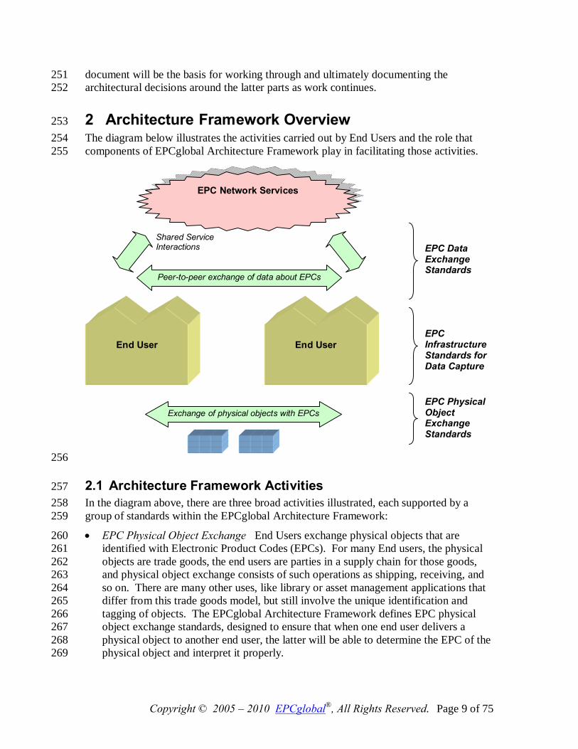
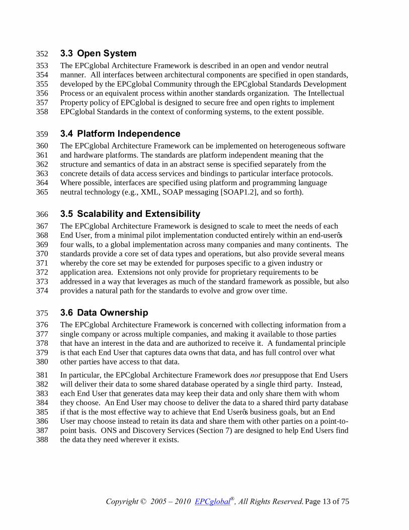
2 Architecture Framework Overview 253 The diagram below illustrates the activities carried out by End Users and the role that 254 components of EPCglobal Architecture Framework play in facilitating those activities. 255
256
2.1 Architecture Framework Activities 257 In the diagram above, there are three broad activities illustrated, each supported by a 258 group of standards within the EPCglobal Architecture Framework: 259
• EPC Physical Object Exchange End Users exchange physical objects that are 260 identified with Electronic Product Codes (EPCs). For many End users, the physical 261 objects are trade goods, the end users are parties in a supply chain for those goods, 262 and physical object exchange consists of such operations as shipping, receiving, and 263 so on. There are many other uses, like library or asset management applications that 264 differ from this trade goods model, but still involve the unique identification and 265 tagging of objects. The EPCglobal Architecture Framework defines EPC physical 266 object exchange standards, designed to ensure that when one end user delivers a 267 physical object to another end user, the latter will be able to determine the EPC of the 268 physical object and interpret it properly. 269
End User
End User
EPC Physical Object Exchange Standards
EPC Infrastructure Standards for Data Capture
EPC Data Exchange Standards
EPC Network Services
Exchange of physical objects with EPCs
Peer-to-peer exchange of data about EPCs
Shared Service Interactions
Copyright © 2005 – 2010 EPCglobal®, All Rights Reserved. Page 10 of 75
• EPC Data Exchange End Users benefit from the EPCglobal Architecture 270 Framework by exchanging data with each other, increasing the visibility they have 271 with respect to the movement of physical objects outside their four walls. The 272 EPCglobal Architecture Framework defines EPC data exchange standards, which 273 provide a means for end users to share data about EPCs within defined user groups or 274 with the general public, and which also provide access to EPC Network Services and 275 other shared services that facilitate these exchanges. 276
• EPC Infrastructure for Data Capture In order to have EPC data to share, each end 277 user carries out operations within its four walls that create EPCs for new objects, 278 follow the movements of objects by sensing their EPCs, and gather that information 279 into systems of record within the organization. The EPCglobal Architecture 280 Framework defines interface standards for the major infrastructure components 281 required to gather and record EPC data, thus allowing end users to build their internal 282 systems using interoperable components. 283
This division of activities is helpful in understanding the overall organization and scope 284 of the EPCglobal Architecture Framework, but should not be considered as extremely 285 rigid. While in many cases, the first two categories refer to cross-enterprise interactions 286 while the third category describes intra-enterprise operations, this is not always true. For 287 example, an organization may use EPCs to track the movement of purely internal assets, 288 in which case it will apply the physical object exchange standards in a situation where 289 there is no actual cross-enterprise exchange. Conversely, an enterprise may outsource 290 some of its internal operations so that the infrastructure standards end up being applied 291 across company boundaries. The EPCglobal Architecture Framework has been designed 292 to give End Users a wide range of options in applying the standards to suit the needs of 293 their particular business operations. 294
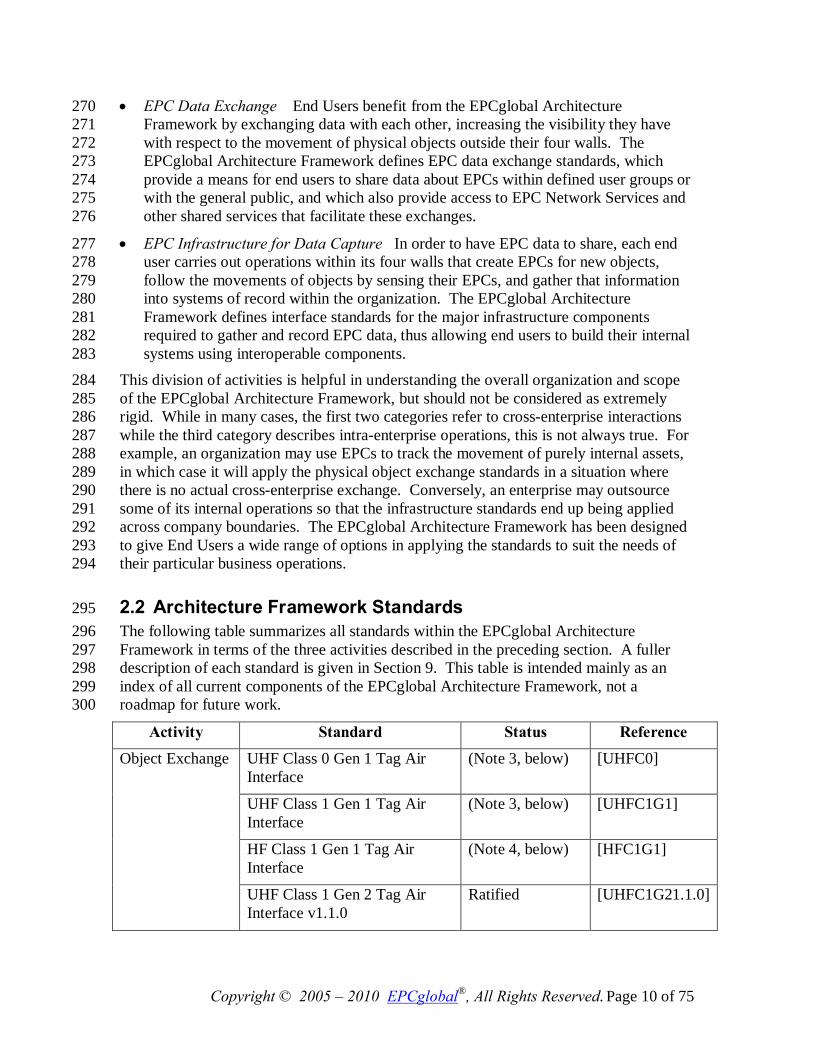
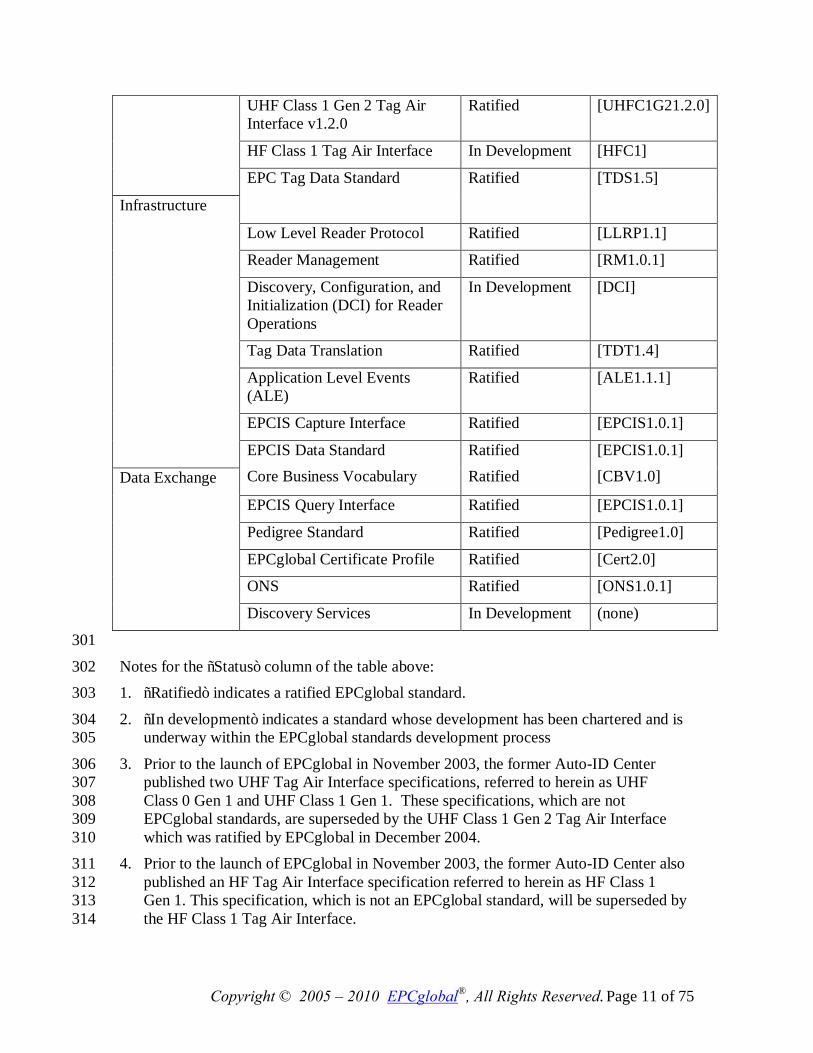
2.2 Architecture Framework Standards 295 The following table summarizes all standards within the EPCglobal Architecture 296 Framework in terms of the three activities described in the preceding section. A fuller 297 description of each standard is given in Section 9. This table is intended mainly as an 298 index of all current components of the EPCglobal Architecture Framework, not a 299 roadmap for future work. 300
Activity Standard Status Reference UHF Class 0 Gen 1 Tag Air Interface
(Note 3, below) [UHFC0]
UHF Class 1 Gen 1 Tag Air Interface
(Note 3, below) [UHFC1G1]
HF Class 1 Gen 1 Tag Air Interface
(Note 4, below) [HFC1G1]
Object Exchange
UHF Class 1 Gen 2 Tag Air Interface v1.1.0
Ratified [UHFC1G21.1.0]
Copyright © 2005 – 2010 EPCglobal®, All Rights Reserved. Page 11 of 75
UHF Class 1 Gen 2 Tag Air Interface v1.2.0
Ratified [UHFC1G21.2.0]
HF Class 1 Tag Air Interface In Development [HFC1]
EPC Tag Data Standard Ratified [TDS1.5]
Low Level Reader Protocol Ratified [LLRP1.1]
Reader Management Ratified [RM1.0.1]
Discovery, Configuration, and Initialization (DCI) for Reader Operations
In Development [DCI]
Tag Data Translation Ratified [TDT1.4]
Application Level Events (ALE)
Ratified [ALE1.1.1]
EPCIS Capture Interface Ratified [EPCIS1.0.1]
Infrastructure
EPCIS Data Standard Core Business Vocabulary
Ratified Ratified
[EPCIS1.0.1] [CBV1.0]
EPCIS Query Interface Ratified [EPCIS1.0.1]
Pedigree Standard Ratified [Pedigree1.0]
EPCglobal Certificate Profile Ratified [Cert2.0]
ONS Ratified [ONS1.0.1]
Data Exchange
Discovery Services In Development (none)
301
Notes for the “Status” column of the table above: 302 1. “Ratified” indicates a ratified EPCglobal standard. 303
2. “In development” indicates a standard whose development has been chartered and is 304 underway within the EPCglobal standards development process 305
3. Prior to the launch of EPCglobal in November 2003, the former Auto-ID Center 306 published two UHF Tag Air Interface specifications, referred to herein as UHF 307 Class 0 Gen 1 and UHF Class 1 Gen 1. These specifications, which are not 308 EPCglobal standards, are superseded by the UHF Class 1 Gen 2 Tag Air Interface 309 which was ratified by EPCglobal in December 2004. 310
4. Prior to the launch of EPCglobal in November 2003, the former Auto-ID Center also 311 published an HF Tag Air Interface specification referred to herein as HF Class 1 312 Gen 1. This specification, which is not an EPCglobal standard, will be superseded by 313 the HF Class 1 Tag Air Interface. 314
Copyright © 2005 – 2010 EPCglobal®, All Rights Reserved. Page 12 of 75
In the table above, the EPCIS Data Standard is shown as spanning the categories of 315 infrastructure standard and data exchange standard. Likewise, the EPC Tag Data 316 Standard is shown spanning the categories of object exchange standard and infrastructure 317 standard, though in fact it also spans the data exchange category. 318
3 Goals for the EPCglobal Architecture Framework 319 This section outlines high-level goals for the EPCglobal Architecture Framework in 320 terms of the benefits provided to End Users. 321
3.1 The Role of Standards 322 EPCglobal standards are created to further the following objectives: 323
• To facilitate the exchange of information and physical objects between trading 324 partners. 325
For trading partners to exchange information, they must have prior agreement as to 326 the structure and meaning of data to be exchanged, and the mechanisms by which 327 exchange will be carried out. EPCglobal standards include data standards and 328 information exchange standards that form the basis of cross-enterprise exchange. 329 Likewise, for trading partners to exchange physical objects, they must have prior 330 agreement as to how physical objects will carry Electronic Product Codes in a 331 mutually understandable way. EPCglobal standards include standards for RFID 332 devices and data standards governing the encoding of EPCs on those devices. 333
• To foster the existence of a competitive marketplace for system components. 334 EPCglobal standards define interfaces between system components that facilitate 335 interoperability from components produced by different vendors (or in house). This 336 in turn provides choice to end users, both in implementing systems that will exchange 337 information between trading partners, and systems that are used entirely within four 338 walls. 339
• To encourage innovation 340 EPCglobal standards define interfaces, not implementations. Implementers are 341 encouraged to innovate in the products and systems they create, while interface 342 standards ensure interoperability between competing systems. 343
3.2 Global Standards 344 EPCglobal is committed to the creation and use of end user driven, royalty-free, global 345 standards. This approach ensures that the EPCglobal Architecture Framework will work 346 anywhere in the world and provides incentives for Solution Providers to support the 347 framework. EPCglobal standards are developed for global use. EPCglobal is committed 348 to making use of existing global standards when appropriate, and EPCglobal works with 349 recognized global standards organizations to incorporate standards created within 350 EPCglobal. 351
Copyright © 2005 – 2010 EPCglobal®, All Rights Reserved. Page 13 of 75
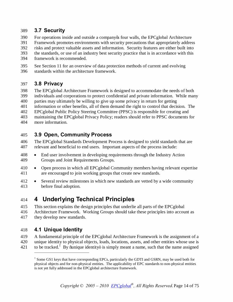
3.3 Open System 352 The EPCglobal Architecture Framework is described in an open and vendor neutral 353 manner. All interfaces between architectural components are specified in open standards, 354 developed by the EPCglobal Community through the EPCglobal Standards Development 355 Process or an equivalent process within another standards organization. The Intellectual 356 Property policy of EPCglobal is designed to secure free and open rights to implement 357 EPCglobal Standards in the context of conforming systems, to the extent possible. 358
3.4 Platform Independence 359 The EPCglobal Architecture Framework can be implemented on heterogeneous software 360 and hardware platforms. The standards are platform independent meaning that the 361 structure and semantics of data in an abstract sense is specified separately from the 362 concrete details of data access services and bindings to particular interface protocols. 363 Where possible, interfaces are specified using platform and programming language 364 neutral technology (e.g., XML, SOAP messaging [SOAP1.2], and so forth). 365
3.5 Scalability and Extensibility 366 The EPCglobal Architecture Framework is designed to scale to meet the needs of each 367 End User, from a minimal pilot implementation conducted entirely within an end-user’s 368 four walls, to a global implementation across many companies and many continents. The 369 standards provide a core set of data types and operations, but also provide several means 370 whereby the core set may be extended for purposes specific to a given industry or 371 application area. Extensions not only provide for proprietary requirements to be 372 addressed in a way that leverages as much of the standard framework as possible, but also 373 provides a natural path for the standards to evolve and grow over time. 374
3.6 Data Ownership 375 The EPCglobal Architecture Framework is concerned with collecting information from a 376 single company or across multiple companies, and making it available to those parties 377 that have an interest in the data and are authorized to receive it. A fundamental principle 378 is that each End User that captures data owns that data, and has full control over what 379 other parties have access to that data. 380
In particular, the EPCglobal Architecture Framework does not presuppose that End Users 381 will deliver their data to some shared database operated by a single third party. Instead, 382 each End User that generates data may keep their data and only share them with whom 383 they choose. An End User may choose to deliver the data to a shared third party database 384 if that is the most effective way to achieve that End User’s business goals, but an End 385 User may choose instead to retain its data and share them with other parties on a point-to-386 point basis. ONS and Discovery Services (Section 7) are designed to help End Users find 387 the data they need wherever it exists. 388
Copyright © 2005 – 2010 EPCglobal®, All Rights Reserved. Page 14 of 75
3.7 Security 389 For operations inside and outside a company’s four walls, the EPCglobal Architecture 390 Framework promotes environments with security precautions that appropriately address 391 risks and protect valuable assets and information. Security features are either built into 392 the standards, or use of an industry best security practice that is in accordance with this 393 framework is recommended. 394 See Section 11 for an overview of data protection methods of current and evolving 395 standards within the architecture framework. 396
3.8 Privacy 397 The EPCglobal Architecture Framework is designed to accommodate the needs of both 398 individuals and corporations to protect confidential and private information. While many 399 parties may ultimately be willing to give up some privacy in return for getting 400 information or other benefits, all of them demand the right to control that decision. The 401 EPCglobal Public Policy Steering Committee (PPSC) is responsible for creating and 402 maintaining the EPCglobal Privacy Policy; readers should refer to PPSC documents for 403 more information. 404
3.9 Open, Community Process 405 The EPCglobal Standards Development Process is designed to yield standards that are 406 relevant and beneficial to end users. Important aspects of the process include: 407
• End user involvement in developing requirements through the Industry Action 408 Groups and Joint Requirements Groups. 409
• Open process in which all EPCglobal Community members having relevant expertise 410 are encouraged to join working groups that create new standards. 411
• Several review milestones in which new standards are vetted by a wide community 412 before final adoption. 413
4 Underlying Technical Principles 414 This section explains the design principles that underlie all parts of the EPCglobal 415 Architecture Framework. Working Groups should take these principles into account as 416 they develop new standards. 417
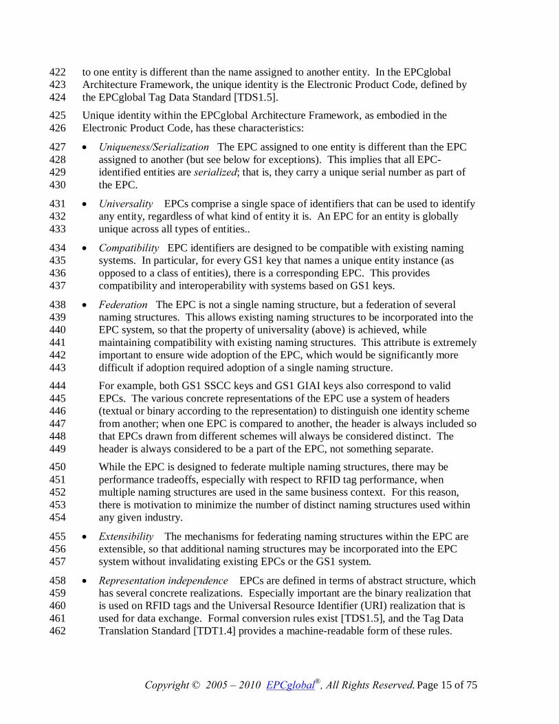
4.1 Unique Identity 418 A fundamental principle of the EPCglobal Architecture Framework is the assignment of a 419 unique identity to physical objects, loads, locations, assets, and other entities whose use is 420 to be tracked.1 By “unique identity” is simply meant a name, such that the name assigned 421 1 Some GS1 keys that have corresponding EPCs, particularly the GDTI and GSRN, may be used both for physical objects and for non-physical entities. The applicability of EPC standards to non-physical entities is not yet fully addressed in the EPCglobal architecture framework.
Copyright © 2005 – 2010 EPCglobal®, All Rights Reserved. Page 15 of 75
to one entity is different than the name assigned to another entity. In the EPCglobal 422 Architecture Framework, the unique identity is the Electronic Product Code, defined by 423 the EPCglobal Tag Data Standard [TDS1.5]. 424 Unique identity within the EPCglobal Architecture Framework, as embodied in the 425 Electronic Product Code, has these characteristics: 426
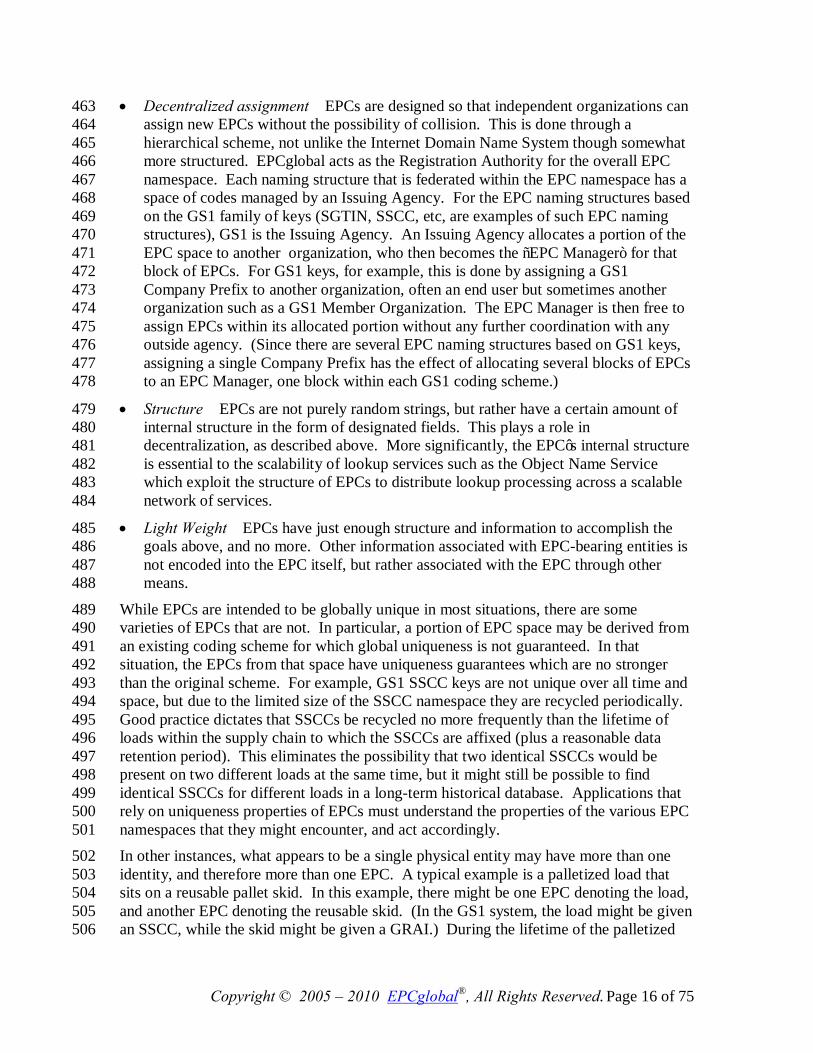
• Uniqueness/Serialization The EPC assigned to one entity is different than the EPC 427 assigned to another (but see below for exceptions). This implies that all EPC-428 identified entities are serialized; that is, they carry a unique serial number as part of 429 the EPC. 430
• Universality EPCs comprise a single space of identifiers that can be used to identify 431 any entity, regardless of what kind of entity it is. An EPC for an entity is globally 432 unique across all types of entities.. 433
• Compatibility EPC identifiers are designed to be compatible with existing naming 434 systems. In particular, for every GS1 key that names a unique entity instance (as 435 opposed to a class of entities), there is a corresponding EPC. This provides 436 compatibility and interoperability with systems based on GS1 keys. 437
• Federation The EPC is not a single naming structure, but a federation of several 438 naming structures. This allows existing naming structures to be incorporated into the 439 EPC system, so that the property of universality (above) is achieved, while 440 maintaining compatibility with existing naming structures. This attribute is extremely 441 important to ensure wide adoption of the EPC, which would be significantly more 442 difficult if adoption required adoption of a single naming structure. 443
For example, both GS1 SSCC keys and GS1 GIAI keys also correspond to valid 444 EPCs. The various concrete representations of the EPC use a system of headers 445 (textual or binary according to the representation) to distinguish one identity scheme 446 from another; when one EPC is compared to another, the header is always included so 447 that EPCs drawn from different schemes will always be considered distinct. The 448 header is always considered to be a part of the EPC, not something separate. 449 While the EPC is designed to federate multiple naming structures, there may be 450 performance tradeoffs, especially with respect to RFID tag performance, when 451 multiple naming structures are used in the same business context. For this reason, 452 there is motivation to minimize the number of distinct naming structures used within 453 any given industry. 454
• Extensibility The mechanisms for federating naming structures within the EPC are 455 extensible, so that additional naming structures may be incorporated into the EPC 456 system without invalidating existing EPCs or the GS1 system. 457
• Representation independence EPCs are defined in terms of abstract structure, which 458 has several concrete realizations. Especially important are the binary realization that 459 is used on RFID tags and the Universal Resource Identifier (URI) realization that is 460 used for data exchange. Formal conversion rules exist [TDS1.5], and the Tag Data 461 Translation Standard [TDT1.4] provides a machine-readable form of these rules. 462
Copyright © 2005 – 2010 EPCglobal®, All Rights Reserved. Page 16 of 75
• Decentralized assignment EPCs are designed so that independent organizations can 463 assign new EPCs without the possibility of collision. This is done through a 464 hierarchical scheme, not unlike the Internet Domain Name System though somewhat 465 more structured. EPCglobal acts as the Registration Authority for the overall EPC 466 namespace. Each naming structure that is federated within the EPC namespace has a 467 space of codes managed by an Issuing Agency. For the EPC naming structures based 468 on the GS1 family of keys (SGTIN, SSCC, etc, are examples of such EPC naming 469 structures), GS1 is the Issuing Agency. An Issuing Agency allocates a portion of the 470 EPC space to another organization, who then becomes the “EPC Manager” for that 471 block of EPCs. For GS1 keys, for example, this is done by assigning a GS1 472 Company Prefix to another organization, often an end user but sometimes another 473 organization such as a GS1 Member Organization. The EPC Manager is then free to 474 assign EPCs within its allocated portion without any further coordination with any 475 outside agency. (Since there are several EPC naming structures based on GS1 keys, 476 assigning a single Company Prefix has the effect of allocating several blocks of EPCs 477 to an EPC Manager, one block within each GS1 coding scheme.) 478
• Structure EPCs are not purely random strings, but rather have a certain amount of 479 internal structure in the form of designated fields. This plays a role in 480 decentralization, as described above. More significantly, the EPC’s internal structure 481 is essential to the scalability of lookup services such as the Object Name Service 482 which exploit the structure of EPCs to distribute lookup processing across a scalable 483 network of services. 484
• Light Weight EPCs have just enough structure and information to accomplish the 485 goals above, and no more. Other information associated with EPC-bearing entities is 486 not encoded into the EPC itself, but rather associated with the EPC through other 487 means. 488
While EPCs are intended to be globally unique in most situations, there are some 489 varieties of EPCs that are not. In particular, a portion of EPC space may be derived from 490 an existing coding scheme for which global uniqueness is not guaranteed. In that 491 situation, the EPCs from that space have uniqueness guarantees which are no stronger 492 than the original scheme. For example, GS1 SSCC keys are not unique over all time and 493 space, but due to the limited size of the SSCC namespace they are recycled periodically. 494 Good practice dictates that SSCCs be recycled no more frequently than the lifetime of 495 loads within the supply chain to which the SSCCs are affixed (plus a reasonable data 496 retention period). This eliminates the possibility that two identical SSCCs would be 497 present on two different loads at the same time, but it might still be possible to find 498 identical SSCCs for different loads in a long-term historical database. Applications that 499 rely on uniqueness properties of EPCs must understand the properties of the various EPC 500 namespaces that they might encounter, and act accordingly. 501
In other instances, what appears to be a single physical entity may have more than one 502 identity, and therefore more than one EPC. A typical example is a palletized load that 503 sits on a reusable pallet skid. In this example, there might be one EPC denoting the load, 504 and another EPC denoting the reusable skid. (In the GS1 system, the load might be given 505 an SSCC, while the skid might be given a GRAI.) During the lifetime of the palletized 506
Copyright © 2005 – 2010 EPCglobal®, All Rights Reserved. Page 17 of 75
load these two EPCs appear to be associated with the same physical entity, but when the 507 load is broken down the load EPC is decommissioned, while the pallet skid EPC 508 continues to live as long as the pallet is reused. In this example, what appears to be one 509 physical entity really consists of two separate entities from a business perspective (the 510 pallet and the load), and so what appears to be multiple EPCs assigned to the same object 511 is really a separate EPC for each entity. 512
4.1.1 Uniqueness Considerations for “Closed” Systems 513 It is sometimes believed that global uniqueness is not required or is prohibitively 514 expensive when EPC technology is used for “closed” systems, such as proprietary use 515 within a single company. Closer analysis suggests that this is not so, as explained below. 516 At the level of information systems (e.g., at the level of EPCIS), the cost of achieving 517 global uniqueness for identifiers is extremely low, and so it is recommended even for 518 closed systems. EPC standards use Internet Uniform Resource Identifiers (URIs) as the 519 standard syntax for unique identifiers, and the EPC Tag Data Standard provides a URI 520 form for Electronic Product Codes in accordance with this principle. URIs are a widely 521 adopted mechanism for construction of globally unique identifiers, and may be used even 522 in applications that do not use EPCs. 523 When RFID tags are used in a “closed” system, the motivation for using globally unique 524 identifiers such as EPCs is even more significant. RFID tags communicate without line 525 of sight from relatively long distances. It is projected that RFID/EPC technology will 526 have substantial consumer use, proliferating the numbers of RFID tags “in the wild.” For 527 these reasons, a truly “closed” system is in most cases not realistically achievable when 528 RFID tags are used. If non-unique identifiers are used in RFID applications, those 529 applications may fail to operate properly, and they may cause other applications to fail. 530 RFID tags containing globally unique EPCs from standards-based open system will enter 531 into closed systems, causing conflicts if those closed systems inappropriately occupy 532 identifier space defined by standards. RFID tags containing identifiers from closed 533 systems will enter into standards-based open systems, causing conflicts in the same way. 534 RFID tags from one closed system will enter into other closed systems, causing conflicts 535 if those systems happen to have chosen identical or overlapping ranges of supposed 536 “private use” identifiers. 537
This last example of RFID tags crossing from one closed system to another is the largest 538 cause of concern. For example, an IT asset-tagging system with a proprietary identifier 539 format operates properly until a second proprietary system for document tracking from 540 another vendor, which happens to use the same “private use” identifiers, is installed. 541 Since there is no coordination between the two systems, the two systems could fail to 542 operate in overt or subtle ways. Such issues are difficult to resolve as there is no 543 common format among the proprietary systems or vendors to troubleshoot and coordinate 544 the changes necessary to ensure uniqueness. 545
In short, there is no such thing as a “closed” system involving RFID tags; any RFID 546 application must consider the possibility that tags from “outside” the system may enter. 547
Copyright © 2005 – 2010 EPCglobal®, All Rights Reserved. Page 18 of 75
The hierarchical encoding structure within the EPC Tag Data Standard provides a 548 globally unique identifier space for both open and closed RFID systems. The most 549 practical method available today to assure proper operation of any system, open or 550 “closed,” is to obtain an EPC manager number and use one of the formats defined in the 551 EPC Tag Data Standard. 552
4.1.2 Use of the Electronic Product Code 553 The Electronic Product Code is designed to facilitate business processes and applications 554 that need to manipulate visibility data – data about observations of physical objects. The 555 EPC is a universal identifier that provides a unique identity for any physical object. The 556 EPC is designed to be unique across all physical objects in the world, over all time, and 557 across all categories of physical objects. (Though see Section 4.1, above, for situations in 558 which an EPC may not be unique over all time.) It is expressly intended for use by 559 business applications that need to track all categories of physical objects, whatever they 560 may be. 561 By contrast, the seven GS1 identification keys defined in the GS1 General Specifications 562 [GS1GS] can identify categories of objects (GTIN), unique objects (SSCC, GLN, GIAI, 563 GSRN), or a hybrid (GRAI, GTDI) that may identify either categories or unique objects 564 depending on the absence or presence of a serial number. The GTIN, as the only 565 category identification key, requires a separate serial number to uniquely identify an 566 object but that serial number is not considered part of the identification key. 567
There is a well-defined correspondence between EPCs and GS1 keys. This allows any 568 physical object that is already identified by a GS1 key to be used in an EPC context 569 where any category of physical object may be observed. Likewise, it allows EPC data 570 captured in a broad visibility context to be correlated with other business data that is 571 specific to the category of object involved and which uses GS1 keys. 572 The remainder of this section elaborates on these points. 573
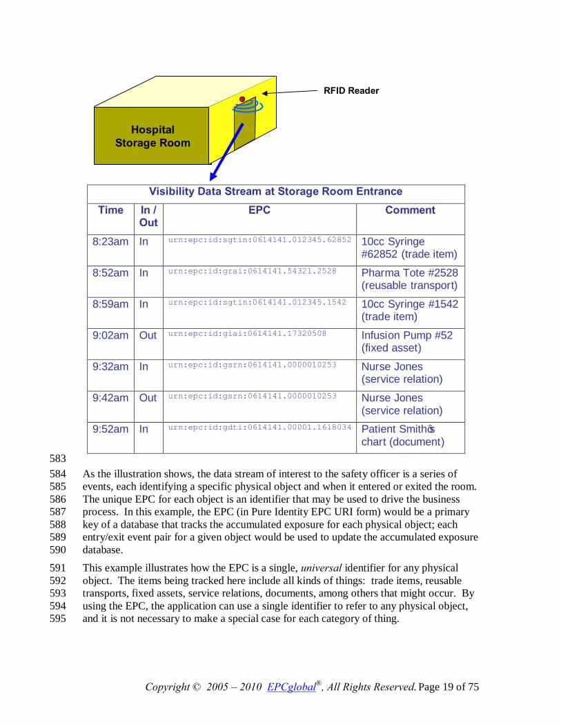
4.1.3 The Need for a Universal Identifier: an Example 574 The following example illustrates how visibility data arises, and the role the EPC plays as 575 a unique identifier for any physical object. In this example, there is a storage room in a 576 hospital that holds radioactive samples, among other things. The hospital safety officer 577 needs to track what things have been in the storage room and for how long, in order to 578 ensure that exposure is kept within acceptable limits. Each physical object that might 579 enter the storage room is given a unique Electronic Product Code, which is encoded onto 580 an RFID Tag affixed to the object. An RFID reader positioned at the storage room door 581 generates visibility data as objects enter and exit the room, as illustrated below. 582
Copyright © 2005 – 2010 EPCglobal®, All Rights Reserved. Page 19 of 75
583 As the illustration shows, the data stream of interest to the safety officer is a series of 584 events, each identifying a specific physical object and when it entered or exited the room. 585 The unique EPC for each object is an identifier that may be used to drive the business 586 process. In this example, the EPC (in Pure Identity EPC URI form) would be a primary 587 key of a database that tracks the accumulated exposure for each physical object; each 588 entry/exit event pair for a given object would be used to update the accumulated exposure 589 database. 590
This example illustrates how the EPC is a single, universal identifier for any physical 591 object. The items being tracked here include all kinds of things: trade items, reusable 592 transports, fixed assets, service relations, documents, among others that might occur. By 593 using the EPC, the application can use a single identifier to refer to any physical object, 594 and it is not necessary to make a special case for each category of thing. 595
Visibility Data Stream at Storage Room Entrance Time In /
Out EPC Comment
8:23am In urn:epc:id:sgtin:0614141.012345.62852 10cc Syringe #62852 (trade item)
8:52am In urn:epc:id:grai:0614141.54321.2528 Pharma Tote #2528 (reusable transport)
8:59am In urn:epc:id:sgtin:0614141.012345.1542 10cc Syringe #1542 (trade item)
9:02am Out urn:epc:id:giai:0614141.17320508 Infusion Pump #52 (fixed asset)
9:32am In urn:epc:id:gsrn:0614141.0000010253 Nurse Jones (service relation)
9:42am Out urn:epc:id:gsrn:0614141.0000010253 Nurse Jones (service relation)
9:52am In urn:epc:id:gdti:0614141.00001.1618034 Patient Smith’s chart (document)
RFID Reader
Hospital
Storage Room
Copyright © 2005 – 2010 EPCglobal®, All Rights Reserved. Page 20 of 75
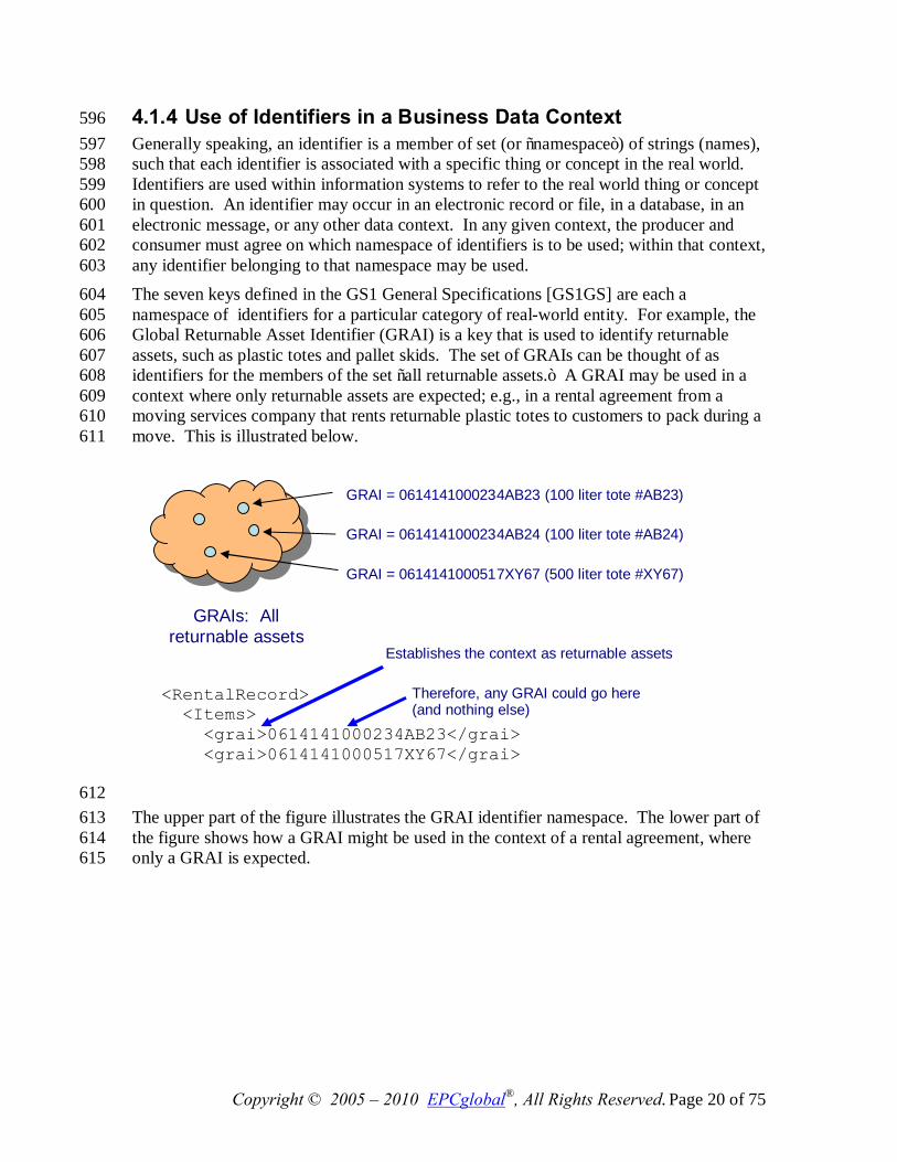
4.1.4 Use of Identifiers in a Business Data Context 596 Generally speaking, an identifier is a member of set (or “namespace”) of strings (names), 597 such that each identifier is associated with a specific thing or concept in the real world. 598 Identifiers are used within information systems to refer to the real world thing or concept 599 in question. An identifier may occur in an electronic record or file, in a database, in an 600 electronic message, or any other data context. In any given context, the producer and 601 consumer must agree on which namespace of identifiers is to be used; within that context, 602 any identifier belonging to that namespace may be used. 603 The seven keys defined in the GS1 General Specifications [GS1GS] are each a 604 namespace of identifiers for a particular category of real-world entity. For example, the 605 Global Returnable Asset Identifier (GRAI) is a key that is used to identify returnable 606 assets, such as plastic totes and pallet skids. The set of GRAIs can be thought of as 607 identifiers for the members of the set “all returnable assets.” A GRAI may be used in a 608 context where only returnable assets are expected; e.g., in a rental agreement from a 609 moving services company that rents returnable plastic totes to customers to pack during a 610 move. This is illustrated below. 611
612 The upper part of the figure illustrates the GRAI identifier namespace. The lower part of 613 the figure shows how a GRAI might be used in the context of a rental agreement, where 614 only a GRAI is expected. 615
GRAI = 0614141000234AB23 (100 liter tote #AB23)
GRAI = 0614141000517XY67 (500 liter tote #XY67)
GRAI = 0614141000234AB24 (100 liter tote #AB24)
GRAIs: All returnable assets
<RentalRecord> <Items> <grai>0614141000234AB23</grai> <grai>0614141000517XY67</grai> …
Establishes the context as returnable assets
Therefore, any GRAI could go here (and nothing else)
Copyright © 2005 – 2010 EPCglobal®, All Rights Reserved. Page 21 of 75
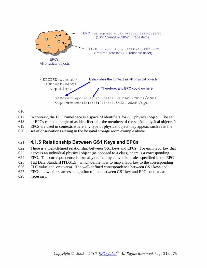
616 In contrast, the EPC namespace is a space of identifiers for any physical object. The set 617 of EPCs can be thought of as identifiers for the members of the set “all physical objects.” 618 EPCs are used in contexts where any type of physical object may appear, such as in the 619 set of observations arising in the hospital storage room example above. 620
4.1.5 Relationship Between GS1 Keys and EPCs 621 There is a well-defined relationship between GS1 keys and EPCs. For each GS1 key that 622 denotes an individual physical object (as opposed to a class), there is a corresponding 623 EPC. This correspondence is formally defined by conversion rules specified in the EPC 624 Tag Data Standard [TDS1.5], which define how to map a GS1 key to the corresponding 625 EPC value and vice versa. The well-defined correspondence between GS1 keys and 626 EPCs allows for seamless migration of data between GS1 key and EPC contexts as 627 necessary. 628
EPCs: All physical objects
EPC = urn:epc:id:sgtin:0614141.012345.62852 (10cc Syringe #62852 – trade item)
EPC = urn:epc:id:grai:0614141.54321.2528 (Pharma Tote #2528 – reusable asset)
<EPCISDocument> <ObjectEvent> <epcList> <epc>urn:epc:id:sgtin:0614141.012345.62852</epc> <epc>urn:epc:id:grai:0614141.54321.2528</epc> …
Establishes the context as all physical objects
Therefore, any EPC could go here
Copyright © 2005 – 2010 EPCglobal®, All Rights Reserved. Page 22 of 75
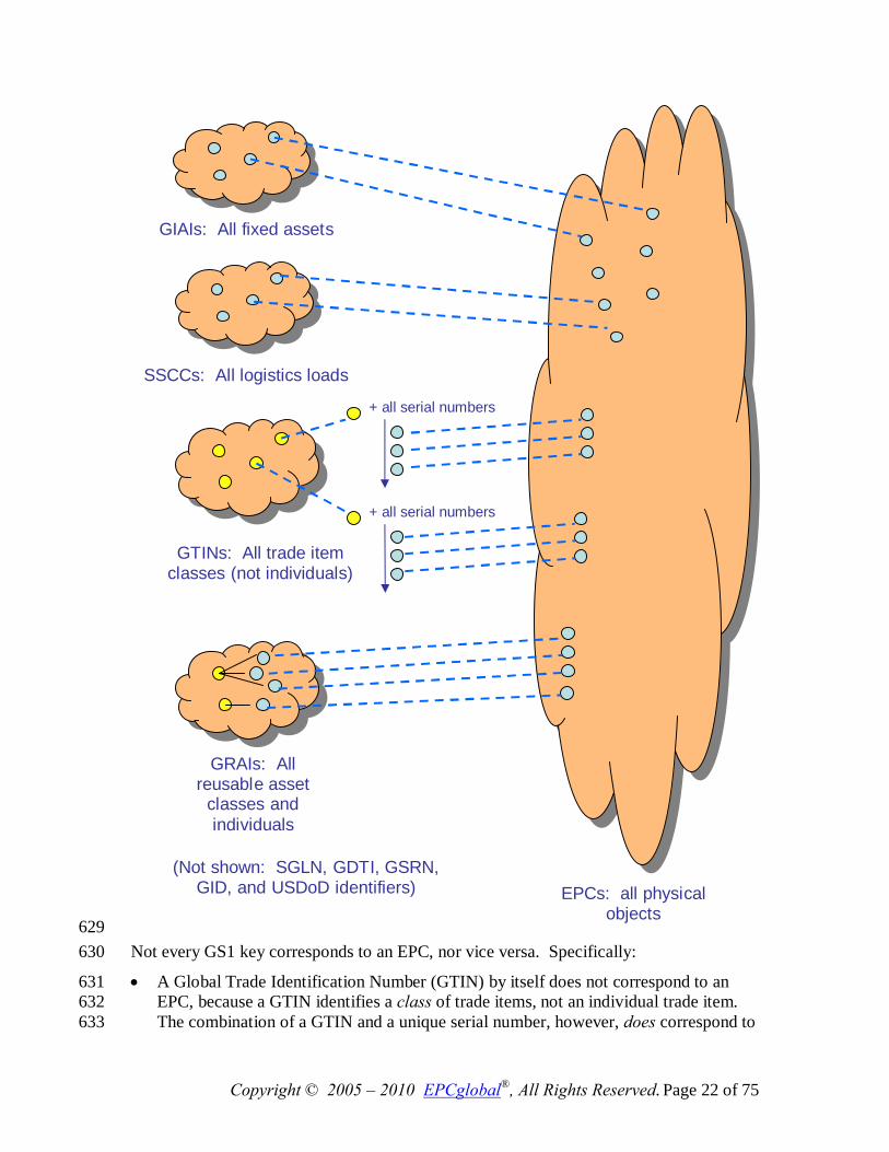
629 Not every GS1 key corresponds to an EPC, nor vice versa. Specifically: 630
• A Global Trade Identification Number (GTIN) by itself does not correspond to an 631 EPC, because a GTIN identifies a class of trade items, not an individual trade item. 632 The combination of a GTIN and a unique serial number, however, does correspond to 633
GIAIs: All fixed assets
SSCCs: All logistics loads
EPCs: all physical objects
GTINs: All trade item classes (not individuals)
+ all serial numbers
GRAIs: All reusable asset
classes and individuals
+ all serial numbers
(Not shown: SGLN, GDTI, GSRN, GID, and USDoD identifiers)
Copyright © 2005 – 2010 EPCglobal®, All Rights Reserved. Page 23 of 75
an EPC. This combination is called a Serialized Global Trade Identification Number, 634 or SGTIN. The GS1 General Specifications, as of Version 9 do not define the SGTIN 635 as a GS1 key (though this point is under discussion and may change in a future 636 version of the GS1 General Specifications). 637
• In the GS1 General Specifications, the Global Returnable Asset Identifier (GRAI) can 638 be used to identify either a class of returnable assets, or an individual returnable asset, 639 depending on whether the optional serial number is included. Only the form that 640 includes a serial number, and thus identifies an individual, has a corresponding EPC. 641 The same is true for the Global Document Type Identifier (GDTI). 642
• There is an EPC corresponding to each Global Location Number (GLN), and there is 643 also an EPC corresponding to each combination of a GLN with an extension 644 component. Collectively, these EPCs are referred to as Serialized Global Location 645 Numbers (SGLNs).2 646
• EPCs include identifiers for which there is no corresponding GS1 key at all. These 647 include the General Identifier and the US Department of Defense identifier . 648
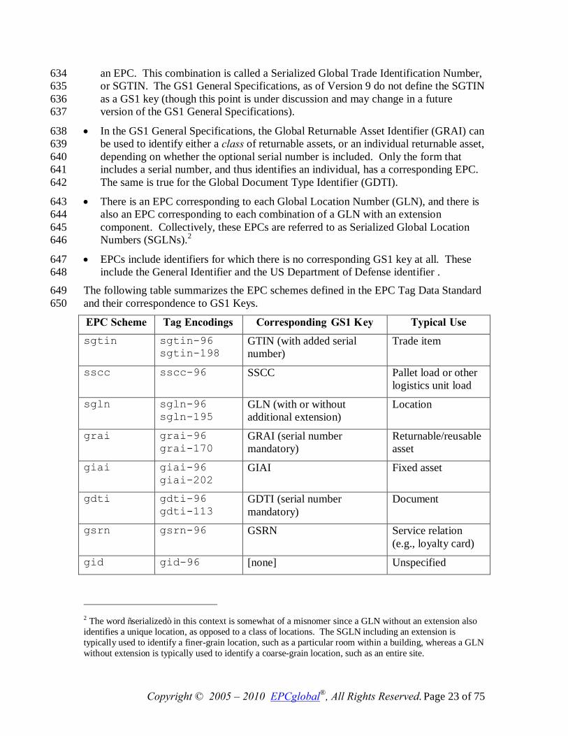
The following table summarizes the EPC schemes defined in the EPC Tag Data Standard 649 and their correspondence to GS1 Keys. 650
EPC Scheme Tag Encodings Corresponding GS1 Key Typical Use sgtin sgtin-96
sgtin-198 GTIN (with added serial number)
Trade item
sscc sscc-96 SSCC Pallet load or other logistics unit load
sgln sgln-96 sgln-195
GLN (with or without additional extension)
Location
grai grai-96 grai-170
GRAI (serial number mandatory)
Returnable/reusable asset
giai giai-96 giai-202
GIAI Fixed asset
gdti gdti-96 gdti-113
GDTI (serial number mandatory)
Document
gsrn gsrn-96 GSRN Service relation (e.g., loyalty card)
gid gid-96 [none] Unspecified
2 The word “serialized” in this context is somewhat of a misnomer since a GLN without an extension also identifies a unique location, as opposed to a class of locations. The SGLN including an extension is typically used to identify a finer-grain location, such as a particular room within a building, whereas a GLN without extension is typically used to identify a coarse-grain location, such as an entire site.
Copyright © 2005 – 2010 EPCglobal®, All Rights Reserved. Page 24 of 75
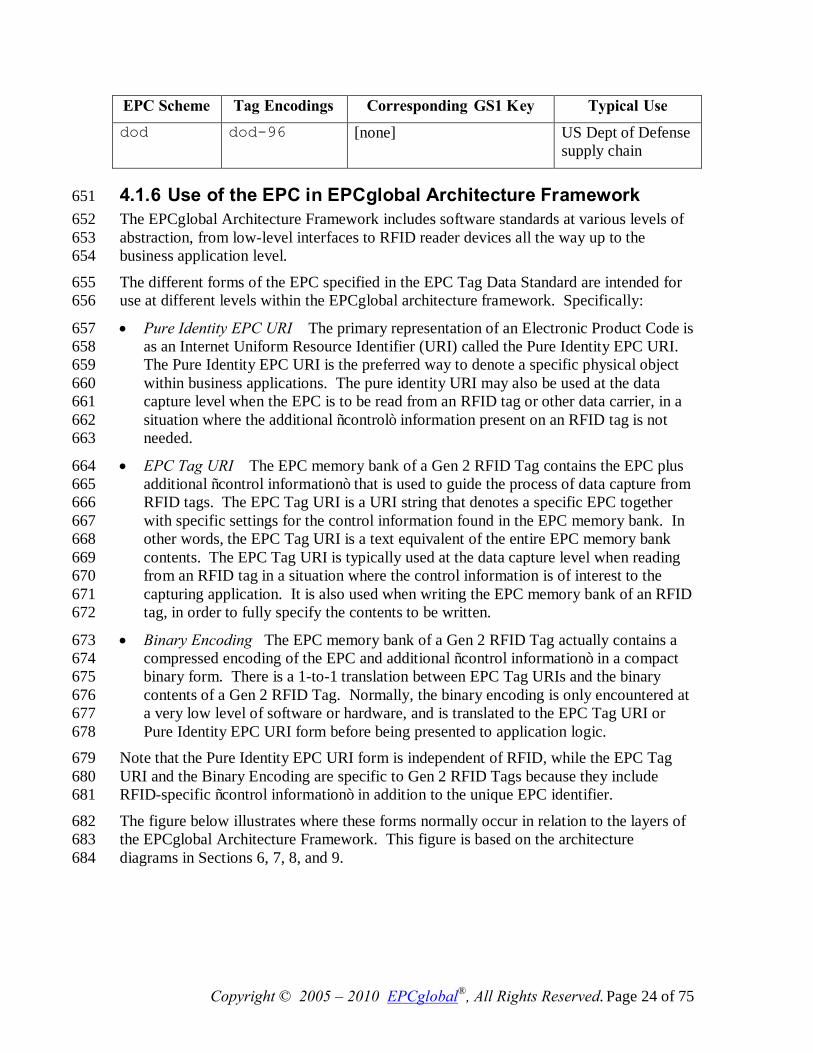
EPC Scheme Tag Encodings Corresponding GS1 Key Typical Use dod dod-96 [none] US Dept of Defense
supply chain
4.1.6 Use of the EPC in EPCglobal Architecture Framework 651 The EPCglobal Architecture Framework includes software standards at various levels of 652 abstraction, from low-level interfaces to RFID reader devices all the way up to the 653 business application level. 654
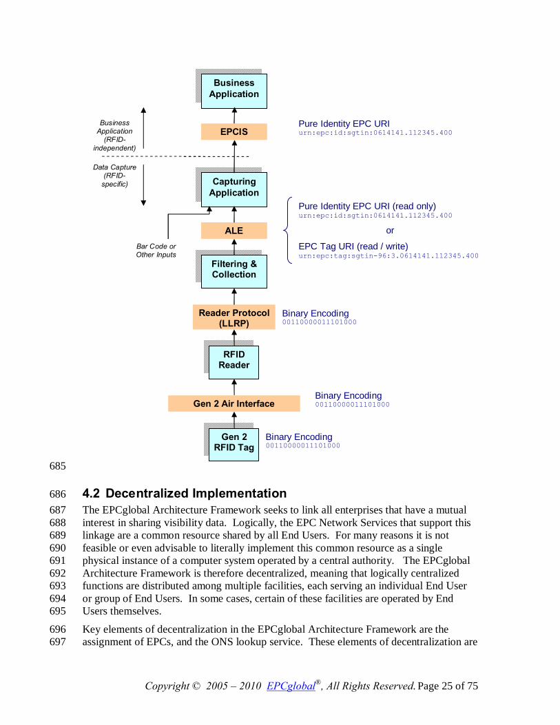
The different forms of the EPC specified in the EPC Tag Data Standard are intended for 655 use at different levels within the EPCglobal architecture framework. Specifically: 656
• Pure Identity EPC URI The primary representation of an Electronic Product Code is 657 as an Internet Uniform Resource Identifier (URI) called the Pure Identity EPC URI. 658 The Pure Identity EPC URI is the preferred way to denote a specific physical object 659 within business applications. The pure identity URI may also be used at the data 660 capture level when the EPC is to be read from an RFID tag or other data carrier, in a 661 situation where the additional “control” information present on an RFID tag is not 662 needed. 663
• EPC Tag URI The EPC memory bank of a Gen 2 RFID Tag contains the EPC plus 664 additional “control information” that is used to guide the process of data capture from 665 RFID tags. The EPC Tag URI is a URI string that denotes a specific EPC together 666 with specific settings for the control information found in the EPC memory bank. In 667 other words, the EPC Tag URI is a text equivalent of the entire EPC memory bank 668 contents. The EPC Tag URI is typically used at the data capture level when reading 669 from an RFID tag in a situation where the control information is of interest to the 670 capturing application. It is also used when writing the EPC memory bank of an RFID 671 tag, in order to fully specify the contents to be written. 672
• Binary Encoding The EPC memory bank of a Gen 2 RFID Tag actually contains a 673 compressed encoding of the EPC and additional “control information” in a compact 674 binary form. There is a 1-to-1 translation between EPC Tag URIs and the binary 675 contents of a Gen 2 RFID Tag. Normally, the binary encoding is only encountered at 676 a very low level of software or hardware, and is translated to the EPC Tag URI or 677 Pure Identity EPC URI form before being presented to application logic. 678
Note that the Pure Identity EPC URI form is independent of RFID, while the EPC Tag 679 URI and the Binary Encoding are specific to Gen 2 RFID Tags because they include 680 RFID-specific “control information” in addition to the unique EPC identifier. 681
The figure below illustrates where these forms normally occur in relation to the layers of 682 the EPCglobal Architecture Framework. This figure is based on the architecture 683 diagrams in Sections 6, 7, 8, and 9. 684
Copyright © 2005 – 2010 EPCglobal®, All Rights Reserved. Page 25 of 75
685
4.2 Decentralized Implementation 686 The EPCglobal Architecture Framework seeks to link all enterprises that have a mutual 687 interest in sharing visibility data. Logically, the EPC Network Services that support this 688 linkage are a common resource shared by all End Users. For many reasons it is not 689 feasible or even advisable to literally implement this common resource as a single 690 physical instance of a computer system operated by a central authority. The EPCglobal 691 Architecture Framework is therefore decentralized, meaning that logically centralized 692 functions are distributed among multiple facilities, each serving an individual End User 693 or group of End Users. In some cases, certain of these facilities are operated by End 694 Users themselves. 695
Key elements of decentralization in the EPCglobal Architecture Framework are the 696 assignment of EPCs, and the ONS lookup service. These elements of decentralization are 697
RFID Reader
Business Application
Data Capture (RFID-
specific)
Business Application
(RFID- independent)
Filtering & Collection
Capturing Application
ALE
EPCIS
Reader Protocol (LLRP)
Gen 2 RFID Tag
Pure Identity EPC URI urn:epc:id:sgtin:0614141.112345.400
Pure Identity EPC URI (read only) urn:epc:id:sgtin:0614141.112345.400
or
EPC Tag URI (read / write) urn:epc:tag:sgtin-96:3.0614141.112345.400
Binary Encoding 00110000011101000…
Gen 2 Air Interface Binary Encoding 00110000011101000…
Binary Encoding 00110000011101000…
Bar Code or Other Inputs
Copyright © 2005 – 2010 EPCglobal®, All Rights Reserved. Page 26 of 75
discussed in more detail in Sections 5.2, 7.1, and 7.3. Other elements of decentralization 698 arise from each End User deploying its own systems that implement EPCglobal 699 Standards. For example, the EPCglobal Architecture Framework does not include a 700 global, centralized repository for visibility information. Instead, global visibility is 701 achieved by each End User deploying his own systems to capture and store visibility 702 data, and sharing that data with other End Users using the EPCIS standard. 703
4.3 Layering of Data Standards – Verticalization 704 The EPCglobal Architecture Framework includes standards for data exchange that are 705 intended to serve the needs of many different industries. Yet, each industry has specific 706 requirements around what data needs to be exchanged and what it means. 707 Consequently, EPCglobal standards that govern data are designed in a layered fashion. 708 Within each data standard, there is a framework layer that applies equally to all industries 709 that use the EPCglobal Architecture Framework. Layered on top of this are several 710 vertical data standards that populate the general framework, each serving the needs of 711 particular industry groups. Vertical data standards may be broad or narrow in their 712 applicability: in many cases a vertical standard will serve several industries that share 713 common business processes, while in other cases a vertical standard will be particular to 714 one industry. It is even possible for a private group of trading partners to develop their 715 own specifications atop the framework similar to a vertical standard. The framework 716 layers tend to be developed by EPCglobal technical action groups, while the requirements 717 for vertical standards tend to be developed by appropriate industry groups. 718
The two important data standards are the EPC Tag Data Standard, and the EPCIS Data 719 Standard. Within the EPC Tag Data Standard, the framework elements include the 720 structure of the “header bits” in the binary EPC representations and the general URI 721 structure of the text-based EPC representations. Both of these features serve to 722 distinguish one coding scheme from another. The vertical layer of the EPC Tag Data 723 Standard are the specific coding schemes defined for particular industry groups. 724 Within the EPCIS Data Standard, the framework elements include the abstract data 725 model that lays out a general organization for master data and visibility event data. The 726 vertical layers of the EPCIS Data Standard define specific event types, master data 727 vocabularies, and master data attributes used within a particular industry. 728
4.4 Layering of Software Standards—Implementation 729 Technology Neutral 730
The EPCglobal Architecture Framework is primarily concerned with the exploitation of 731 new data derived from the use of Electronic Product Codes and RFID technology within 732 business processes. To foster the broadest possible applicability for EPCglobal 733 standards, EPCglobal software standards are, whenever possible, defined using a layered 734 approach. In this approach, the abstract content of data and/or services is defined using a 735 technology-neutral description language such as UML. Separately, the abstract 736 specifications are given one or more bindings to specific implementation technology such 737 as XML, web services, and so forth. As most of the technical substance of EPCglobal 738
Copyright © 2005 – 2010 EPCglobal®, All Rights Reserved. Page 27 of 75
standards exists in the abstract content, this approach helps ensure that even when 739 different implementation technologies are used in different deployments there is a strong 740 commonality in what the systems do. 741
4.5 Extensibility 742 The EPCglobal Architecture Framework explicitly recognizes the fact that change is 743 inevitable. A general design principle for all EPCglobal Standards is openness to 744 extension. Extensions include both enhancements to the standards themselves, through 745 the introduction of new versions of a standard, and extensions made by a particular 746 enterprise, group of cooperating enterprises, or industry vertical, to address specific needs 747 that are not appropriate to address in an EPCglobal standard. 748 All EPCglobal Standards have identified points where extensions may be made, and 749 provide explicit mechanisms for doing so. As far as is practical, the extension 750 mechanisms are designed to promote both backward compatibility (a newer or extended 751 implementation should continue to interoperate with an older implementation) and 752 forward compatibility (an older implementation should continue to interoperate with a 753 newer or extended implementation, though it may not be able to exploit the new 754 features). The extension mechanisms are also designed so that non-standard extensions 755 may be made independently by multiple groups, without the possibility of conflict or 756 collision. 757 Non-standard extensions are accommodated not only because they are necessary to meet 758 specific requirements that individual enterprises, groups, or industry verticals may have, 759 but also because it is an excellent way to experiment with new innovations that will 760 ultimately become standardized through newer versions of EPCglobal Standards. The 761 extension mechanisms are designed to provide a smooth path for this migration. 762
5 Architectural Foundations 763 This section describes the key design elements at the foundations of the EPCglobal 764 Architecture Framework. This sets the stage for the detailed description of the 765 framework given in Sections 6, 7, and 8. 766
5.1 Electronic Product Code 767 As previously described in Section 4.1, the Electronic Product Code is the embodiment of 768 the underlying principle of unique identity. Electronic Product Codes are assigned to 769 physical objects, loads, locations, assets, and other entities which are to be tracked using 770 components of the EPCglobal Architecture Framework in service of a given industry’s 771 business goals. The Electronic Product Code is the thread that ties together all data that 772 flows between End Users, and plays a central part in every role and interface within the 773 EPCglobal Architecture Framework. 774
Copyright © 2005 – 2010 EPCglobal®, All Rights Reserved. Page 28 of 75
5.2 EPC Manager 775 As noted in Section 4.1, a key characteristic of identity as used in the EPCglobal 776 Architecture Framework is decentralization. Decentralization is achieved through the 777 notion of an EPC Manager. Within this document, the term “EPC Manager” refers to an 778 organization who has been granted rights by an Issuing Agency to use a portion of the 779 EPC namespace. That is, the Issuing Agency has effectively issued the EPC Manager 780 one or more blocks of Electronic Product Codes within designated coding schemes that 781 the EPC Manager can independently assign to physical objects and other entities without 782 further involvement of the Issuing Agency. The EPC Manager is said to be the 783 “managing authority” for the EPCs in this block. In many cases, the EPC Manager is the 784 manufacturer of a product, but this is not always the case as discussed below. 785
The EPC Manager has two special responsibilities within the EPCglobal Architecture 786 Framework that distinguish it from all other End Users, with respect to the EPCs it 787 manages: 788
• The EPC Manager is responsible for ensuring that the appropriate uniqueness 789 properties are maintained (see Section 4.1) as EPCs are allocated from the EPC 790 Manager’s assigned block. In many cases, the EPC Manager is also the organization 791 that actually allocates a specific EPC and associates it with a physical object or other 792 entity (an act called “commissioning”). In other cases, the EPC Manager delegates 793 responsibility for commissioning individual EPCs to another organization, in which 794 case it must do so in a manner that ensures uniqueness. 795
• The EPC Manager is responsible for maintaining the Object Name Service (ONS) 796 records associated with blocks of EPCs it manages. ONS records are the point of 797 entry for certain types of global lookup operations as described in later sections. 798 (This responsibility is limited to those blocks of EPCs that are allocated by the EPC 799 Manager for objects that are exchanged with other End Users; any EPC blocks 800 reserved for internal use by the EPC Manager need not be reflected in ONS. Also, if 801 the EPC Manager chooses not to share data with trading partners, it may elect not to 802 provide ONS lookup for any or all of its EPC blocks, in which case there is obviously 803 no requirement to maintain ONS records for those EPC blocks.) 804
Other than these two responsibilities, the EPC Manager has no special responsibilities 805 with respect to the EPCs it manages compared to any other End User. In particular, both 806 the EPC Manager and other end users may participate equally in the generation and 807 exchange of EPC-related data. 808
5.3 EPC Manager Number 809 The way that an Issuing Agency grants a block of EPCs to an EPC Manager is by issuing 810 the EPC Manager a single number, called the EPC Manager Number. An End User or 811 other organization may hold multiple Manager Numbers, and therefore be in control of 812 multiple blocks of EPCs. The structure of all coding schemes within the Electronic 813 Product Code definition is such that the EPC Manager Number appears as a distinct field 814 within any given representation. The EPC Manager Number should not be assumed to be 815 the product manufacturer when derived from GS1 keys (see Section 5.4.1). 816
Copyright © 2005 – 2010 EPCglobal®, All Rights Reserved. Page 29 of 75
Having the EPC Manager Number as a distinct field within any given representation 817 allows any system to instantly identify the EPC Manager associated with a given EPC. 818 This property is very important to insure the scalability of the overall system, as it allows 819 services that would otherwise be centralized to be delegated to each EPC Manager as 820 appropriate. For example, an ONS lookup is conceptually a lookup in a single large table 821 that maps any EPC to the location of an EPCIS service, but having the EPC Manager 822 Number as a distinct field allows ONS to be implemented as a collection of tables, each 823 maintained by the EPC Manager for a given block of EPCs (see Section 7.3 for more 824 information on ONS specifically). 825 The allocation of a block of EPCs to an EPC Manager is actually implicit in the act of 826 assigning an EPC Manager Number. The EPC Manager is simply free to commission 827 any EPC so long as the EPC Manager Number field within the EPC contains the assigned 828 EPC Manager Number, following the EPC Tag Data Standard. The “block” of EPCs, 829 therefore, simply consists of all EPCs that contain the assigned EPC Manager Number in 830 the EPC Manager Number field. (This is a slight simplification; see Section 5.4 for more 831 information.) 832
5.4 Correspondence to Existing Codes 833 Most coding schemes currently defined with the EPC Tag Data Standard have a direct 834 correspondence to existing industry coding schemes. For example, there are seven types 835 of EPCs based on GS1 keys [GS1GS]: SGTIN, SSCC, SGLN, GRAI, GIAI, GSRN, and 836 GDTI. In the case of these EPCs, the EPC Manager Number is one and the same as the 837 GS1 Company Prefix that forms the basis of the corresponding GS1 key. The other fields 838 of GS1-based EPCs are also derived from existing fields of the GS1 keys. 839 In general, this kind of correspondence is possible for any existing coding scheme that 840 has a manager-like structure; that is, when the existing coding scheme is based on 841 delegating assignment through the central allocation of a unique prefix or field. The US 842 Department of Defense, for example, has defined an EPC coding scheme based on its 843 own CAGE and DoDAAC codes, which are issued uniquely to DoD suppliers and thus 844 serve as EPC Manager Numbers when used to construct EPCs using the “DoD construct” 845 coding scheme. 846
In the last section, it was noted that assigning an EPC Manager Number to an EPC 847 Manager effectively allocates a block of EPCs to the EPC Manager. Because the 848 Electronic Product Code federates several coding schemes, the “block” of EPCs implied 849 by the assignment of an EPC Manager Number is not necessarily a single contiguous 850 block of numbers, but rather a contiguous block within each EPC identity type to which 851 the EPC Manager Number pertains. For example, when an EPC Manager Number is a 852 GS1 Company Prefix, the EPC Manager is effectively granted a block of EPCs within 853 each of the seven GS1-related EPC types (SGTIN, SSCC, SGLN, GRAI, GIAI, GSRN, 854 and GDTI). But when an EPC Manager Number is a US Department of Defense 855 CAGE/DoDAAC code, the EPC Manager is effectively granted a single block of EPCs, 856 within the “DoD Construct” coding scheme. 857
Copyright © 2005 – 2010 EPCglobal®, All Rights Reserved. Page 30 of 75
5.4.1 An EPC Manager Number Does Not Uniquely Identify a 858 Manufacturer when the Manager Number is Derived from a 859 GS1 Company Prefix 860
In the early days of the UPC, Company Prefixes were in one-to-one correspondence with 861 trade item manufacturers. As the GS1 System has evolved, this is no longer true, for 862 many reasons: 863
• Some manufacturers require more than one GS1 Company Prefix because of the 864 number of GTINs they need to allocate. With a 7-digit Company Prefix, for example, 865 only 100,000 distinct GTINs can be allocated. 866
• When one company acquires another company, the acquiring company typically ends 867 up with both GS1 Company Prefixes. There is typically no motivation to reassign 868 GTINs to the acquired product lines merely to reduce the number of GS1 Company 869 Prefixes in use. 870
• When Company A acquires a product line from Company B (as opposed to the whole 871 company), it may acquire specific GTINs that use the same Company Prefix as the 872 Company B continues to use for other products. GTIN assignment rules require 873 Company A eventually to assign new GTINs to the acquired products, but at least for 874 a time Company A and Company B each have products sharing the same Company 875 Prefix. (Of course, during this time Company A is not entitled to allocate new GTINs 876 using Company B’s prefix.) 877
• An organization possessing a GS1 Company Prefix may subcontract the manufacture 878 of trade items to contract manufacturers. The GTINs for these products may contain 879 the Company Prefix of the contracting organization, not the manufacturers. This is 880 especially typical when a retailer contracts for the manufacturer of private-label 881 merchandise. One retailer’s Company Prefix may be used for products contracted to 882 many different contract manufacturers, and conversely any given contract 883 manufacturer may be manufacturing goods with many different Company Prefixes 884 belonging to different brand owners. 885
• In some instances, a GS1 Company Prefix is assigned to a GS1 Member Organization 886 (MO), which allocates individual GTINs or blocks of GTINs to end user 887 organizations one at a time. This is especially true for MOs in smaller countries, and 888 by all MOs when assigning GTINs suitable for use in the EAN-8 bar code 889 symbology. 890
For all these reasons, the GS1 General Specifications [GS1GS] repeatedly caution against 891 assuming that GS1 Company Prefix is usable as a unique identifier of a specific end user 892 company (despite what the historic phrase “company prefix” appears to imply). 893 Therefore, the EPC Manager Number should not be assumed to be the owner when the 894 EPC corresponds to a GS1 key. In some situations, the GS1 Company Prefix may 895 usefully be used as an approximate way to select EPCs that are related by virtue of 896 having been assigned by the same company. For example, when searching for all EPC 897 data pertaining to a given company, it may be a useful optimization to look for all EPC 898
Copyright © 2005 – 2010 EPCglobal®, All Rights Reserved. Page 31 of 75
data bearing that company’s prefix, then taking exceptions for those GTINs that do not 899 belong to that company because they have been sold to other companies. 900
5.5 Class Level Data versus Instance Level Data 901 EPCs are assigned uniquely to physical objects and other entities, allowing data to be 902 associated with individual objects. For example, one can associate data with a specific 903 24-count case of Cherry Hydro Soda by referring to its unique EPC. 904 In some cases, it is necessary to associate data with a class of object rather than a specific 905 object itself. In the case of consumer goods, an object class refers to all instances of a 906 specific product (Stock Keeping Unit, or SKU); for example, the class representing all 907 24-count cases of Cherry Hydro Soda. For Electronic Product Codes having a three-part 908 structure of EPC Manager Number, Object Class ID, and Serial Number, a product class 909 is uniquely identified by the first two numbers, disregarding the Serial Number. The 910 Serialized Global Trade Item Number (SGTIN) coding scheme is an example of an EPC 911 having this structure. In this particular example, the EPC Manager Number and Object 912 Class ID taken together are in fact in one-to-one correspondence with the GTIN that is 913 used outside of the EPC arena to represent product classes. This is another example of 914 how existing codes relate to the Electronic Product Code framework. 915 Some kinds of Electronic Product Codes are used to identify things that do not have any 916 meaningful grouping into object classes. For example, the Serialized Shipping Container 917 Code is a type of EPC used to identify shipping loads, where each load may contain a 918 unique assortment of products. Codes of this kind often have a two-part structure, as the 919 SSCC does, consisting only of an EPC Manager Number and a Serial Number. 920
5.6 EPC Information Services (EPCIS) 921 The primary vehicle for data exchange between End Users in the EPCglobal Architecture 922 Framework is EPC Information Services (EPCIS). As explained below, EPCIS 923 encompasses both interfaces for data exchange and specifications of the data itself. 924 EPCIS data is information that trading partners share to gain more insight into what is 925 happening to physical objects in locations outside their own four walls. (EPCIS data 926 may, of course, also be used within a company’s four walls.) For most industries using 927 the EPCglobal Architecture Framework, EPCIS data can be divided into five categories, 928 as follows: 929
• Static Data, which does not change over the life of a physical object. This includes: 930
• Class-level Static Data; that is, data which is the same for all objects of a given 931 object class (see Section 5.5). For consumer products, for example, the “class” is 932 the product, or SKU, as opposed to distinct instances of a given product. In many 933 industries, class-level static data may be the subject of existing data 934 synchronization mechanisms such as the Global Data Synchronization Network 935 (GDSN); in such instances, EPCIS may not be the primary means of exchange. 936
• Instance-level Static Data, which may differ from one instance to the next within 937 a given object class. Examples of instance-level static data include such things as 938
Copyright © 2005 – 2010 EPCglobal®, All Rights Reserved. Page 32 of 75
date of manufacture, lot number, expiration date, and so forth. Instance-level 939 static data generally takes the form of attributes associated with specific EPCs. 940
• Transactional Data, which does grow and change over the life of a physical object. 941 This includes: 942
• Instance Observations, which record events that occur in the life of one or more 943 specific EPCs. Examples of instance observations include “EPC X was shipped 944 at 12:03pm 15 March 2004 from Acme Distribution Center #2,” and “At 3:45pm 945 22 Jan 2005 the case EPCs (list here) were aggregated to the pallet EPC X at ABC 946 Corp’s Boston factory.” Most instance observations have four dimensions: time, 947 location, one or more EPCs, and business process step. 948
• Quantity Observations, which record events concerned with measuring the 949 quantity of objects within a particular object class. An example of a quantity 950 observation is “There were 4,100 instances of object class C observed at 2:00am 951 16 Jan 2003 in RetailMart Store #23.” Most quantity observations have five 952 dimensions: time, location, object class, quantity, and business process step. 953
• Business Transaction Observations, which record an association between one or 954 more EPCs and a business transaction. An example of a business transaction 955 observation is “The pallet with EPC X was shipped in fulfillment of Acme Corp 956 purchase order #23 at 2:20pm.” Most business transaction observations have four 957 dimensions: time, one or more EPCs, a business process step, and a business 958 transaction identifier. 959
The EPCIS Data Standards provide a precise definition of all the types of EPCIS data, as 960 well as the meaning of “event” as used above. 961
Transactional data differs from static data not only because as it grows and changes over 962 the life of a physical object, but also because transactional data for a given EPC is 963 typically generated by many distinct end users within a supply chain. For example, 964 consider an object that is manufactured by A, who employs transportation company B to 965 ship to distributor C, who delivers the object by way of 3rd party logistics provider D to 966 retailer E. By the time the object reaches E, all five companies will have gathered 967 transactional data about the EPC. The static data, in contrast, often comes exclusively 968 from the manufacturer A. 969
A key challenge faced by the EPCglobal Architecture Framework is to allow any End 970 User to discover all transactional data to which it is authorized, from any other End User. 971 Section 7.1 discusses how the EPCglobal Architecture Framework addresses this 972 challenge. 973
6 Roles and Interfaces – General Considerations 974 This section and the three sections that follow define the EPCglobal Architecture 975 Framework, describing at a high level all of the EPCglobal Standards and EPC Network 976 Services that comprise it. The normative description of each of these is found elsewhere. 977 In the case of an EPCglobal Standard, the normative description is or will be an 978 EPCglobal standard document. In the case of an EPC Network Service, normative 979
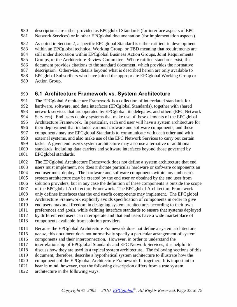
Copyright © 2005 – 2010 EPCglobal®, All Rights Reserved. Page 33 of 75
descriptions are either provided as EPCglobal Standards (for interface aspects of EPC 980 Network Services) or in other EPCglobal documentation (for implementation aspects). 981
As noted in Section 2, a specific EPCglobal Standard is either ratified, in development 982 within an EPCglobal technical Working Group, or TBD meaning that requirements are 983 still under discussion within EPCglobal Business Action Groups, Joint Requirements 984 Groups, or the Architecture Review Committee. Where ratified standards exist, this 985 document provides citations to the standard document, which provides the normative 986 description. Otherwise, details beyond what is described herein are only available to 987 EPCglobal Subscribers who have joined the appropriate EPCglobal Working Group or 988 Action Group. 989
6.1 Architecture Framework vs. System Architecture 990 The EPCglobal Architecture Framework is a collection of interrelated standards for 991 hardware, software, and data interfaces (EPCglobal Standards), together with shared 992 network services that are operated by EPCglobal, its delegates, and others (EPC Network 993 Services). End users deploy systems that make use of these elements of the EPCglobal 994 Architecture Framework. In particular, each end user will have a system architecture for 995 their deployment that includes various hardware and software components, and these 996 components may use EPCglobal Standards to communicate with each other and with 997 external systems, and also make use of the EPC Network Services to carry out certain 998 tasks. A given end user’s system architecture may also use alternative or additional 999 standards, including data carriers and software interfaces beyond those governed by 1000 EPCglobal standards. 1001
The EPCglobal Architecture Framework does not define a system architecture that end 1002 users must implement, nor does it dictate particular hardware or software components an 1003 end user must deploy. The hardware and software components within any end user’s 1004 system architecture may be created by the end user or obtained by the end user from 1005 solution providers, but in any case the definition of these components is outside the scope 1006 of the EPCglobal Architecture Framework. The EPCglobal Architecture Framework 1007 only defines interfaces that the end user’s components may implement. The EPCglobal 1008 Architecture Framework explicitly avoids specification of components in order to give 1009 end users maximal freedom in designing system architectures according to their own 1010 preferences and goals, while defining interface standards to ensure that systems deployed 1011 by different end users can interoperate and that end users have a wide marketplace of 1012 components available from solution providers. 1013
Because the EPCglobal Architecture Framework does not define a system architecture 1014 per se, this document does not normatively specify a particular arrangement of system 1015 components and their interconnection. However, in order to understand the 1016 interrelationship of EPCglobal Standards and EPC Network Services, it is helpful to 1017 discuss how they are used in a typical system architecture. The following sections of this 1018 document, therefore, describe a hypothetical system architecture to illustrate how the 1019 components of the EPCglobal Architecture Framework fit together. It is important to 1020 bear in mind, however, that the following description differs from a true system 1021 architecture in the following ways: 1022
Copyright © 2005 – 2010 EPCglobal®, All Rights Reserved. Page 34 of 75
• An end user system architecture may only need to employ a subset of the EPCglobal 1023 Standards and EPC Network Services depicted here. For example, an RFID 1024 application using EPC tags that exists entirely within the four walls of a single 1025 enterprise may use the UHF Class 1 Gen 2 Tag Air Interface and the EPC Tag Data 1026 Standard, but have no need for the Object Name Service. 1027
• The mapping between hardware and software roles depicted here and actual hardware 1028 or software components deployed by an end user may not necessarily be one-to-one. 1029 For example, to carry out a business process of shipment verification using EPC-1030 encoded RFID tags, one end user may deploy a system in which there is a separate 1031 RFID Reader (a hardware device), Filtering & Collection middleware (software 1032 deployed on a server), and EPCIS Capturing Application (software deployed on a 1033 different server). Another end user may deploy an integrated verification portal 1034 device that combines into a single package all three of these roles, exposing only the 1035 EPCIS Capture Interface. For this reason, this document is careful to refer to roles 1036 rather than components when talking about system elements that make use of 1037 standard interfaces. 1038
• In the same vein, roles depicted here may be carried out by an end user’s legacy 1039 system components that may have additional responsibilities outside the scope of the 1040 EPCglobal Architecture Framework. For example, it is common to have enterprise 1041 applications such as Warehouse Management Systems that simultaneously play the 1042 role of EPCIS Capturing Application (e.g., receiving EPC observations during the 1043 loading of a truck), an EPCIS-enabled Repository (e.g., recording case-to-pallet 1044 associations), and an EPCIS Accessing Application (e.g., carrying out business 1045 decisions based on EPCIS-level data). 1046
The overall intent of the EPCglobal Architecture Framework is to provide end users with 1047 great flexibility in creating system architectures that meet their needs. 1048
6.2 Cross-Enterprise versus Intra-Enterprise 1049 As discussed in Section 2, elements of the EPCglobal Architecture Framework can be 1050 categorized as pertaining to EPC Data Exchange between enterprises, EPC Object 1051 Exchange between enterprises, or EPC Infrastructure deployed within a single enterprise. 1052 Clearly, all End Users will find relevance in the first two categories, as use of these 1053 standards is necessary to interact with other end users. An end user has much more 1054 latitude, however, in its decisions surrounding adoption of the EPC Infrastructure 1055 standards, as those standards do not affect parties outside the end user’s own four walls. 1056
For this reason, the following discussion of roles and interfaces within the EPCglobal 1057 Architecture Framework is divided into two sections, the first dealing with cross-1058 enterprise elements (EPC Data Exchange and EPC Object Exchange), and the second 1059 dealing with intra-enterprise elements (EPC Infrastructure). As explained in Section 2, 1060 however, it should be borne in mind that the division between cross-enterprise and intra-1061 enterprise standards is not absolute, and a given enterprise may employ cross-enterprise 1062 standards entirely within its four walls or conversely use intra-enterprise standards in 1063 collaboration with outside parties. 1064
Copyright © 2005 – 2010 EPCglobal®, All Rights Reserved. Page 35 of 75
7 Data Flow Relationships – Cross-Enterprise 1065 This section provides a diagram showing the relationships between EPCglobal Standards, 1066 from a data flow perspective. This section shows only the EPCglobal Standards that are 1067 typically used between end users, namely those categorized as “EPC Object Exchange 1068 Standards” or “EPC Data Exchange Standards” in Section 2. EPCglobal Standards that 1069 are primarily used within the four walls of a single end user (“EPC Infrastructure 1070 Standards” from Section 2) are described in Section 8. Most End Users will implement 1071 the architecture given in this section. 1072
In the following diagram, the plain green bars denote interfaces governed by EPCglobal 1073 standards, while the blue “shadowed” boxes denote roles played by hardware and 1074 software components of a typical system architecture. As emphasized in Section 6.1, in 1075 any given end user’s deployment the mapping of roles in this diagram to actual hardware 1076 and software components may not be one-to-one, nor will every end user’s deployment 1077 contain every role shown here. 1078
To emphasize how EPCglobal Standards are employed to share data between partners, 1079 this diagram shows one end user (labeled “End User” in the diagram) who observes a 1080 physical object having an EPC on an RFID tag, and shares data about that observation 1081 with a second end user (labeled “Partner End User”). This interaction is shown as one 1082 way, for clarity. In many situations, the Partner End User may also be observing physical 1083 objects and sharing that data with the first End User. If that is the case, then the full 1084 picture would show a mirror-image set of roles, interfaces, and interactions. 1085 1086
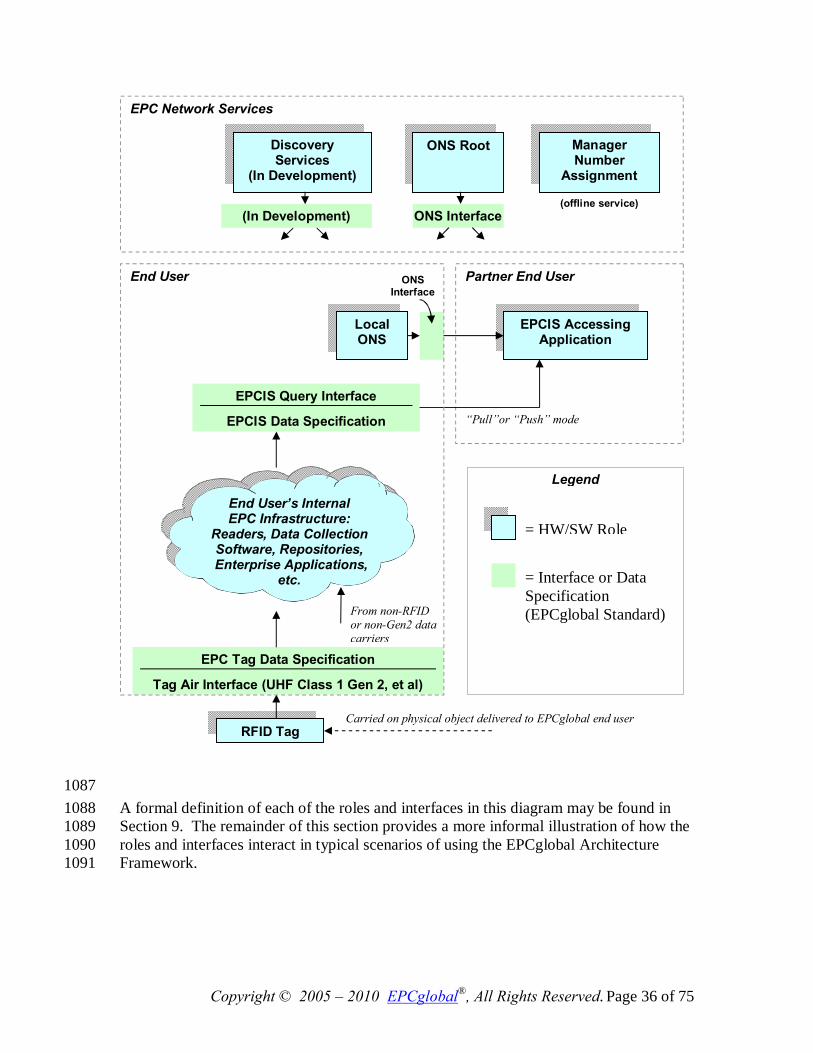
Copyright © 2005 – 2010 EPCglobal®, All Rights Reserved. Page 36 of 75
1087 A formal definition of each of the roles and interfaces in this diagram may be found in 1088 Section 9. The remainder of this section provides a more informal illustration of how the 1089 roles and interfaces interact in typical scenarios of using the EPCglobal Architecture 1090 Framework. 1091
EPCIS Query Interface
EPCIS Data Specification
EPC Tag Data Specification
Tag Air Interface (UHF Class 1 Gen 2, et al)
RFID Tag
EPCIS Accessing Application
“Pull”or “Push” mode
Partner End User End User
Local ONS
ONS Interface
EPC Network Services
ONS Root Discovery Services
(In Development)
Manager Number
Assignment
(offline service) ONS Interface (In Development)
End User’s Internal EPC Infrastructure:
Readers, Data Collection Software, Repositories,
Enterprise Applications, etc.
Carried on physical object delivered to EPCglobal end user
= HW/SW Role
= Interface or Data Specification (EPCglobal Standard)
Legend
From non-RFID or non-Gen2 data carriers
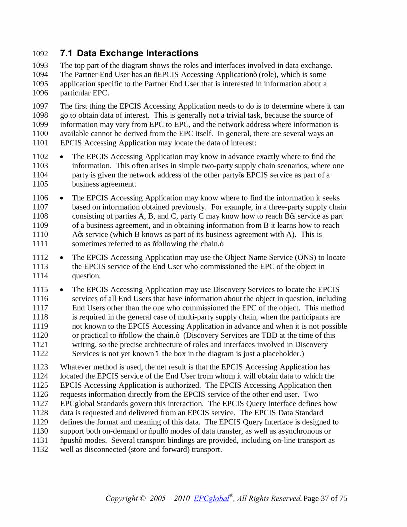
Copyright © 2005 – 2010 EPCglobal®, All Rights Reserved. Page 37 of 75
7.1 Data Exchange Interactions 1092 The top part of the diagram shows the roles and interfaces involved in data exchange. 1093 The Partner End User has an “EPCIS Accessing Application” (role), which is some 1094 application specific to the Partner End User that is interested in information about a 1095 particular EPC. 1096
The first thing the EPCIS Accessing Application needs to do is to determine where it can 1097 go to obtain data of interest. This is generally not a trivial task, because the source of 1098 information may vary from EPC to EPC, and the network address where information is 1099 available cannot be derived from the EPC itself. In general, there are several ways an 1100 EPCIS Accessing Application may locate the data of interest: 1101
• The EPCIS Accessing Application may know in advance exactly where to find the 1102 information. This often arises in simple two-party supply chain scenarios, where one 1103 party is given the network address of the other party’s EPCIS service as part of a 1104 business agreement. 1105
• The EPCIS Accessing Application may know where to find the information it seeks 1106 based on information obtained previously. For example, in a three-party supply chain 1107 consisting of parties A, B, and C, party C may know how to reach B’s service as part 1108 of a business agreement, and in obtaining information from B it learns how to reach 1109 A’s service (which B knows as part of its business agreement with A). This is 1110 sometimes referred to as “following the chain.” 1111
• The EPCIS Accessing Application may use the Object Name Service (ONS) to locate 1112 the EPCIS service of the End User who commissioned the EPC of the object in 1113 question. 1114
• The EPCIS Accessing Application may use Discovery Services to locate the EPCIS 1115 services of all End Users that have information about the object in question, including 1116 End Users other than the one who commissioned the EPC of the object. This method 1117 is required in the general case of multi-party supply chain, when the participants are 1118 not known to the EPCIS Accessing Application in advance and when it is not possible 1119 or practical to “follow the chain.” (Discovery Services are TBD at the time of this 1120 writing, so the precise architecture of roles and interfaces involved in Discovery 1121 Services is not yet known – the box in the diagram is just a placeholder.) 1122
Whatever method is used, the net result is that the EPCIS Accessing Application has 1123 located the EPCIS service of the End User from whom it will obtain data to which the 1124 EPCIS Accessing Application is authorized. The EPCIS Accessing Application then 1125 requests information directly from the EPCIS service of the other end user. Two 1126 EPCglobal Standards govern this interaction. The EPCIS Query Interface defines how 1127 data is requested and delivered from an EPCIS service. The EPCIS Data Standard 1128 defines the format and meaning of this data. The EPCIS Query Interface is designed to 1129 support both on-demand or “pull” modes of data transfer, as well as asynchronous or 1130 “push” modes. Several transport bindings are provided, including on-line transport as 1131 well as disconnected (store and forward) transport. 1132
Copyright © 2005 – 2010 EPCglobal®, All Rights Reserved. Page 38 of 75
When an EPCIS Accessing Application of the Partner End User accesses the EPCIS 1133 service of the first End User, the first End User will usually want to authenticate the 1134 identity of the Partner End User in order to determine what data the latter is authorized to 1135 receive. The EPCglobal Architecture Framework allows the use of a variety of 1136 authentication technologies across its defined interfaces. It is expected, however, that the 1137 X.509 authentication framework will be widely employed by End Users. If X.509 1138 certificates are used, they should comply with the standards defined in the EPCglobal 1139 X.509 Certificate Profile [Cert2.0], which provides a minimum level of cryptographic 1140 security and defines and standardizes identification parameters for users, services/servers 1141 and devices. In some situations, an End User may grant EPCIS access to another party 1142 whose identity is not authenticated or authenticated by means other than those facilitated 1143 by EPCglobal. This is a policy decision that is up to each End User to make. 1144
7.2 Object Exchange Interactions 1145 The lower part of the diagram illustrates how the first End User interacts with physical 1146 objects it receives from other end users. A physical object is received by the End User, 1147 bearing an RFID tag that contains an EPC. The End User reads the tag using RFID 1148 Readers deployed as part of its internal EPC infrastructure. Two EPCglobal Standards 1149 govern this interaction. A Tag Air Interface defines how data is communicated via radio 1150 signals between RFID Tags and RFID Readers. The EPC Tag Data Standard defines the 1151 format and meaning of this data, including the EPC and other data on the Tag. 1152
Within the End User’s internal EPC infrastructure, there may be many hardware and 1153 software components involved in obtaining and processing the tag read, integrating the 1154 tag read into an ongoing business process, and ultimately using the tag read to help in 1155 creating an EPCIS event that can be made available to a Partner End User via EPCIS as 1156 previously described. A single tag read could in theory result in a new EPCIS event by 1157 itself; far more commonly, each EPCIS event results from many tag reads together with 1158 other information derived from the business context in which the tag (or tags) were read. 1159 Some scenarios of how this takes place are illustrated in Section 8. 1160
7.3 ONS Interactions 1161 In Section 7.1, it was mentioned that one End User may locate the EPCIS service of the 1162 organization that commissioned a given EPC by using the Object Name Service, or ONS. 1163 This section describes in somewhat more detail how this takes place as a collaboration 1164 between an EPC Network Service and a service provided by an individual end user. 1165
The Object Name Service can be thought of as a simple lookup service that takes an EPC 1166 as input, and produces as output the address (in the form of a Uniform Resource Locator, 1167 or URL) of an EPCIS service designated by the EPC Manager of the EPC in question. 1168 (An EPC Manager may actually use ONS to associate several different services, not just 1169 an EPCIS service, with an EPC. All of the following discussion applies equally 1170 regardless of which type of service is looked up.) In general, there may be many 1171 different object classes that fall under the authority of a single EPC Manager, and it may 1172 not be the case that all object classes of a given EPC Manager will have information 1173 provided by the same EPCIS service. This is especially true when the EPC Manager 1174
Copyright © 2005 – 2010 EPCglobal®, All Rights Reserved. Page 39 of 75
delegates the commissioning of EPCs to other organizations; for example, a retailer who 1175 contracts with different manufacturing partners for different private-label product lines. 1176 Therefore, ONS requires a separate entry for each object class. (The current design of 1177 ONS does not, however, permit different entries for different serial numbers of the same 1178 object class. For coding schemes which do not have a field corresponding to object class, 1179 such as the SSCC, GIAI, and GSRN keys, the ONS entry is at the EPC Manager level.) 1180
Conceptually, this is a single global lookup service. It would not be practical, however, 1181 to implement ONS as one gigantic directory, both for reasons of scalability and in 1182 consideration of the difficulty of each EPC Manager organization having to maintain 1183 records for its object classes in a shared database. Instead, ONS is architected as an 1184 application of the Internet Domain Name System (DNS), which is also a single global 1185 lookup service conceptually but is implemented as a hierarchy of lookup services. 1186
ONS works as follows. When an End User application wishes to locate an EPCIS 1187 service, it presents a query to its local DNS resolver (typically provided as part of the 1188 computer’s operating system). The DNS resolver is responsible for carrying out the 1189 query procedure, and returning the result to the requesting application. From the 1190 application’s point of view, the lookup appears to be a single operation. 1191 Inside the resolver, however, a multi-step lookup is performed as follows. First, it 1192 consults the Root ONS service controlled by EPCglobal. The Root ONS service 1193 identifies the Local ONS service of the EPC Manager organization for that EPC. The 1194 End User then completes the lookup by consulting the Local ONS service, which 1195 provides the pointer to the EPCIS service in question. This multi-step lookup procedure 1196 is illustrated below. 1197
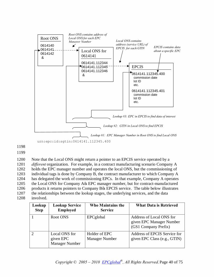
Copyright © 2005 – 2010 EPCglobal®, All Rights Reserved. Page 40 of 75
1198 1199 Note that the Local ONS might return a pointer to an EPCIS service operated by a 1200 different organization. For example, in a contract manufacturing scenario Company A 1201 holds the EPC manager number and operates the local ONS, but the commissioning of 1202 individual tags is done by Company B, the contract manufacturer to which Company A 1203 has delegated the work of commissioning EPCs. In that example, Company A operates 1204 the Local ONS for Company A’s EPC manager number, but for contract-manufactured 1205 products it returns pointers to Company B’s EPCIS service. The table below illustrates 1206 the relationships between the lookup stages, the underlying services, and the data 1207 involved. 1208
Lookup Step
Lookup Service Employed
Who Maintains the Service
What Data is Retrieved
1 Root ONS EPCglobal Address of Local ONS for given EPC Manager Number (GS1 Company Prefix)
2 Local ONS for given EPC Manager Number
Holder of EPC Manager Number
Address of EPCIS Service for given EPC Class (e.g., GTIN)
Root ONS
0614140 0614141 0614142 …
Local ONS for 0614141 0614141.112344 0614141.112345 0614141.112346 …
EPCIS 0614141.112345.400 commission date lot ID etc.
0614141.112345.401 commission date lot ID etc.
Root ONS contains address of Local ONS for each EPC Manager Number Local ONS contains
address (service URL) of EPCIS for each GTIN EPCIS contains data
about a specific EPC
urn:epc:id:sgtin:0614141.112345.400
Lookup #1: EPC Manager Number in Root ONS to find Local ONS
Lookup #2: GTIN in Local ONS to find EPCIS
Lookup #3: EPC in EPCIS to find data of interest
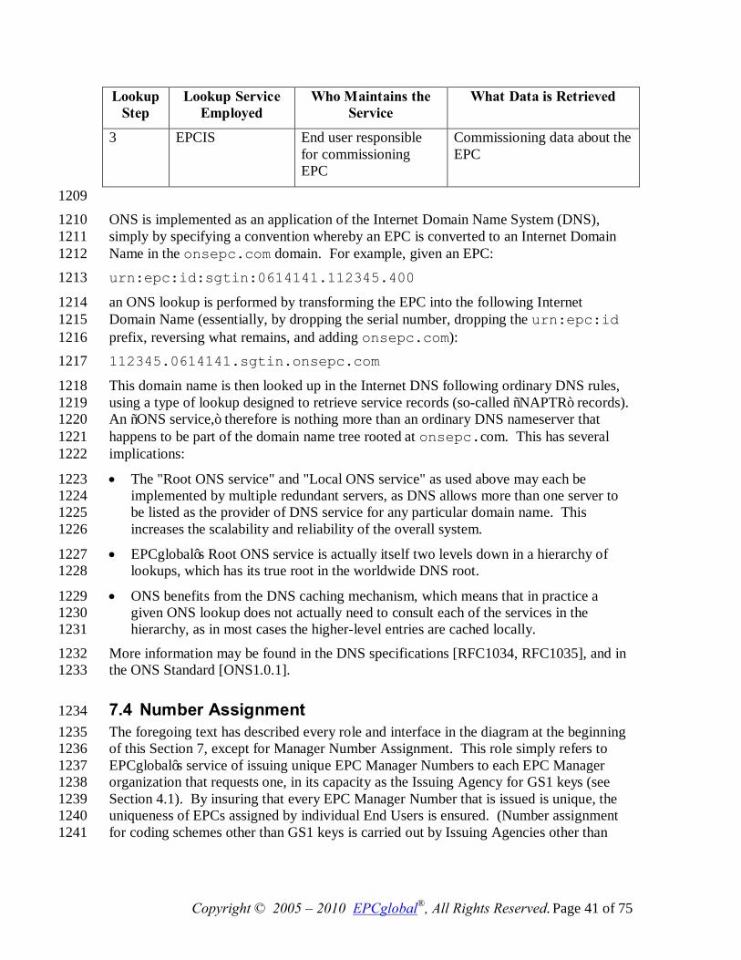
Copyright © 2005 – 2010 EPCglobal®, All Rights Reserved. Page 41 of 75
Lookup Step
Lookup Service Employed
Who Maintains the Service
What Data is Retrieved
3 EPCIS End user responsible for commissioning EPC
Commissioning data about the EPC
1209 ONS is implemented as an application of the Internet Domain Name System (DNS), 1210 simply by specifying a convention whereby an EPC is converted to an Internet Domain 1211 Name in the onsepc.com domain. For example, given an EPC: 1212 urn:epc:id:sgtin:0614141.112345.400 1213
an ONS lookup is performed by transforming the EPC into the following Internet 1214 Domain Name (essentially, by dropping the serial number, dropping the urn:epc:id 1215 prefix, reversing what remains, and adding onsepc.com): 1216 112345.0614141.sgtin.onsepc.com 1217
This domain name is then looked up in the Internet DNS following ordinary DNS rules, 1218 using a type of lookup designed to retrieve service records (so-called “NAPTR” records). 1219 An “ONS service,” therefore is nothing more than an ordinary DNS nameserver that 1220 happens to be part of the domain name tree rooted at onsepc.com. This has several 1221 implications: 1222
• The "Root ONS service" and "Local ONS service" as used above may each be 1223 implemented by multiple redundant servers, as DNS allows more than one server to 1224 be listed as the provider of DNS service for any particular domain name. This 1225 increases the scalability and reliability of the overall system. 1226
• EPCglobal’s Root ONS service is actually itself two levels down in a hierarchy of 1227 lookups, which has its true root in the worldwide DNS root. 1228
• ONS benefits from the DNS caching mechanism, which means that in practice a 1229 given ONS lookup does not actually need to consult each of the services in the 1230 hierarchy, as in most cases the higher-level entries are cached locally. 1231
More information may be found in the DNS specifications [RFC1034, RFC1035], and in 1232 the ONS Standard [ONS1.0.1]. 1233
7.4 Number Assignment 1234 The foregoing text has described every role and interface in the diagram at the beginning 1235 of this Section 7, except for Manager Number Assignment. This role simply refers to 1236 EPCglobal’s service of issuing unique EPC Manager Numbers to each EPC Manager 1237 organization that requests one, in its capacity as the Issuing Agency for GS1 keys (see 1238 Section 4.1). By insuring that every EPC Manager Number that is issued is unique, the 1239 uniqueness of EPCs assigned by individual End Users is ensured. (Number assignment 1240 for coding schemes other than GS1 keys is carried out by Issuing Agencies other than 1241
Copyright © 2005 – 2010 EPCglobal®, All Rights Reserved. Page 42 of 75
EPCglobal, and so EPCglobal’s Manager Number Assignment Service does not apply in 1242 those cases.) 1243
8 Data Flow Relationships – Intra-Enterprise 1244 This section provides a diagram showing the relationships between EPCglobal Standards, 1245 from a data flow perspective. In contrast to Section 7, this section shows only the 1246 EPCglobal Standards that are typically used within the four walls of a single end user, 1247 namely those categorized as “EPC Infrastructure Standards” in Section 2. This section 1248 expands the “cloud” in the diagram from Section 7. Because this cloud is completely 1249 internal to a given enterprise, an end user has much more latitude to deviate from this 1250 picture when appropriate to that end user’s unique business conditions. EPCglobal sets 1251 standards in this area, however, to encourage solution providers to create interoperable 1252 system components from which end users may choose. 1253
As in Section 7, the plain green bars in the diagram below denote interfaces governed by 1254 EPCglobal standards, while the blue “shadowed” boxes denote roles played by hardware 1255 and software components of a typical system architecture. As emphasized in Section 6.1, 1256 in any given end user’s deployment the mapping of roles in this diagram to actual 1257 hardware and software components may not be one-to-one, nor will every end user’s 1258 deployment contain every role shown here. 1259
1260
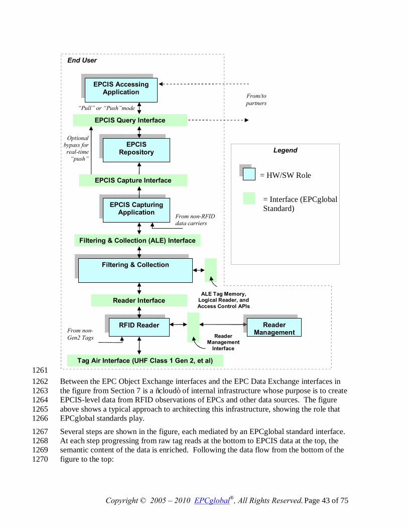
Copyright © 2005 – 2010 EPCglobal®, All Rights Reserved. Page 43 of 75
1261 Between the EPC Object Exchange interfaces and the EPC Data Exchange interfaces in 1262 the figure from Section 7 is a “cloud” of internal infrastructure whose purpose is to create 1263 EPCIS-level data from RFID observations of EPCs and other data sources. The figure 1264 above shows a typical approach to architecting this infrastructure, showing the role that 1265 EPCglobal standards play. 1266
Several steps are shown in the figure, each mediated by an EPCglobal standard interface. 1267 At each step progressing from raw tag reads at the bottom to EPCIS data at the top, the 1268 semantic content of the data is enriched. Following the data flow from the bottom of the 1269 figure to the top: 1270
EPCIS Capture Interface
EPCIS Repository
EPCIS Capturing Application
Reader Interface
Filtering & Collection
EPCIS Query Interface
EPCIS Accessing Application
Tag Air Interface (UHF Class 1 Gen 2, et al)
RFID Reader
Reader Management
Interface
Reader Management
“Pull” or “Push”mode
End User
Optional bypass for real-time
“push”
From/to partners
= HW/SW Role
= Interface (EPCglobal Standard)
Legend
ALE Tag Memory, Logical Reader, and Access Control APIs
Filtering & Collection (ALE) Interface
From non-RFID data carriers
From non-Gen2 Tags
Copyright © 2005 – 2010 EPCglobal®, All Rights Reserved. Page 44 of 75
• Readers Make multiple observations of RFID tags while they are in the read zone. 1271
• Reader Interface Defines the control and delivery of raw tag reads from Readers to 1272 the Filtering & Collection role. Events at this interface say “Reader A saw EPC X at 1273 time T.” 1274
• Filtering & Collection This role filters and collects raw tag reads, over time intervals 1275 delimited by events defined by the EPCIS Capturing Application (e.g. tripping a 1276 motion detector). 1277
• Filtering & Collection (ALE) Interface Defines the control and delivery of filtered 1278 and collected tag read data from Filtering & Collection role to the EPCIS Capturing 1279 Application role. Events at this interface say “At Location L, between time T1 and 1280 T2, the following EPCs were observed,” where the list of EPCs has no duplicates and 1281 has been filtered by criteria defined by the EPCIS Capturing Application. 1282
• EPCIS Capturing Application Supervises the operation of the lower EPC elements, 1283 and provides business context by coordinating with other sources of information 1284 involved in executing a particular step of a business process. The EPCIS Capturing 1285 Application may, for example, coordinate a conveyor system with Filtering & 1286 Collection events, may check for exceptional conditions and take corrective action 1287 (e.g., diverting a bad case into a rework area), may present information to a human 1288 operator, and so on. The EPCIS Capturing Application understands the business 1289 process step or steps during which EPCIS data capture takes place. This role may be 1290 complex, involving the association of multiple Filtering & Collection events with one 1291 or more business events, as in the loading of a shipment. Or it may be 1292 straightforward, as in an inventory business process where there may be “smart 1293 shelves” deployed that generate periodic observations about objects that enter or 1294 leave the shelf. In the latter case, the Filtering & Collection-level event and the 1295 EPCIS-level event may be so similar that no actual processing at the EPCIS 1296 Capturing Application level is necessary, and the EPCIS Capturing Application 1297 merely configures and routes events from the Filtering & Collection interface directly 1298 to an EPCIS-enabled Repository. 1299
• EPCIS Capture Interface The interface through which EPCIS data is delivered to 1300 enterprise-level roles, including EPCIS Repositories, EPCIS Accessing Applications, 1301 and data exchange with partners. Events at this interface say, for example, “At 1302 location X, at time T, the following contained objects (cases) were verified as being 1303 aggregated to the following containing object (pallet).” 1304
• EPCIS Accessing Application Responsible for carrying out overall enterprise 1305 business processes, such as warehouse management, shipping and receiving, 1306 historical throughput analysis, and so forth, aided by EPC-related data. 1307
• EPCIS Repository Software that records EPCIS-level events generated by one or 1308 more EPCIS Capturing Applications, and makes them available for later query by 1309 EPCIS Accessing Applications. 1310
Copyright © 2005 – 2010 EPCglobal®, All Rights Reserved. Page 45 of 75
The interfaces within this stack are designed to insulate the higher levels of the stack 1311 from unnecessary details of how the lower levels are implemented. One way to 1312 understand this is to consider what happens if certain changes are made: 1313
• The Reader Interface insulates the higher layers from knowing what reader 1314 makes/models have been chosen. If a different reader is substituted, the information 1315 at the Reader Interface remains the same. The Reader Interface may, to some extent, 1316 also provide insulation from knowing what Tag Air Interfaces are in use, though 1317 obviously not when one tag type or Tag Air Interface provides fundamentally 1318 different functionality from another. 1319
• The Filtering & Collection Interface insulates the higher layers from the physical 1320 design choices made regarding how tags are sensed and accumulated, and how the 1321 time boundaries of events are triggered. If a single four-antenna reader is replaced by 1322 a constellation of five single-antenna “smart antenna” readers, the events at the 1323 Filtering & Collection level remain the same. Likewise, if a different triggering 1324 mechanism is used to mark the start and end of the time interval over which reads are 1325 accumulated, the Filtering & Collection event remains the same. 1326
• The EPCIS interfaces insulate enterprise applications from understanding the details 1327 of how individual steps in a business process are carried out at a detailed level. For 1328 example, a typical EPCIS event is “At location X, at time T, the following cases were 1329 verified as being on the following pallet.” In a conveyor-based business 1330 implementation, this likely corresponds to a single Filtering & Collection event, in 1331 which reads are accumulated during a time interval whose start and end is triggered 1332 by the case crossing electric eyes surrounding a reader mounted on the conveyor. But 1333 another implementation could involve three strong people who move around the cases 1334 and use hand-held readers to read the EPCs. At the Filtering & Collection level, this 1335 looks very different (each triggering of the hand-held reader is likely a distinct 1336 Filtering & Collection event), and the processing done by the EPCIS Capturing 1337 Application is quite different (perhaps involving an interactive console that the people 1338 use to verify their work). But the EPCIS event is still the same. 1339
In summary, the different steps in the data path correspond to different semantic levels, 1340 and serve to insulate different concerns from one another as data moves up from raw tag 1341 reads towards EPCIS. 1342
Besides the data path described above, there is also a control path responsible for 1343 managing and monitoring of the infrastructure. This includes the Reader Management 1344 standard, the Discovery, Configuration, and Initialization (DCI) standard, and the control 1345 interfaces in the Application Level Events (ALE) standard. 1346
9 Roles and Interfaces – Reference 1347 This section provides a complete reference to all roles and interfaces described in 1348 Sections 7 and 8, describing each in more formal terms. For convenience, the following 1349 diagram combines the figures from the two previous sections into a single figure. As in 1350 Sections 7 and 8, the plain green bars in the diagram below denote interfaces governed by 1351 EPCglobal standards, while the blue “shadowed” boxes denote roles played by hardware 1352
Copyright © 2005 – 2010 EPCglobal®, All Rights Reserved. Page 46 of 75
and software components of a typical system architecture. As emphasized in Section 6.1, 1353 in any given end user’s deployment the mapping of roles in this diagram to actual 1354 hardware and software components may not be one-to-one, nor will every end user’s 1355 deployment contain every role shown here. 1356
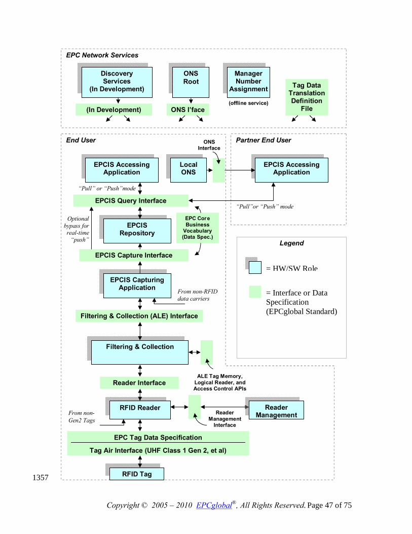
Copyright © 2005 – 2010 EPCglobal®, All Rights Reserved. Page 47 of 75
1357
EPCIS Capture Interface
EPCIS Repository
EPCIS Capturing Application
Reader Interface
Filtering & Collection
EPCIS Query Interface
EPCIS Accessing Application
EPC Tag Data Specification
Tag Air Interface (UHF Class 1 Gen 2, et al)
RFID Reader
RFID Tag
Reader
Management Interface
Reader Management
EPCIS Accessing Application
“Pull”or “Push” mode
“Pull” or “Push”mode
Partner End User End User
Local ONS
ONS Interface
EPC Network Services
ONS Root
Discovery Services
(In Development)
Manager Number
Assignment
(offline service) ONS I’face (In Development)
Optional bypass for real-time
“push”
= HW/SW Role
= Interface or Data Specification (EPCglobal Standard)
Legend
ALE Tag Memory, Logical Reader, and Access Control APIs
Filtering & Collection (ALE) Interface
From non-RFID data carriers
From non-Gen2 Tags
EPC Core Business
Vocabulary (Data Spec.)
Tag Data Translation Definition
File
Copyright © 2005 – 2010 EPCglobal®, All Rights Reserved. Page 48 of 75
The next section explains the roles and interfaces in this diagram in more detail. 1358
9.1 Roles and Interfaces – Responsibilities and Collaborations 1359 This section defines each of the roles and interfaces shown in the diagram above. 1360
9.1.1 RFID Tag (Role) 1361
EPCglobal has defined a tag classification system to describe tag functionality. The 1362 responsibilities of the RFID Tag role based on classification are shown below. 1363 EPCglobal is still evaluating responsibilities and roles for the tag classifications beyond 1364 Class1. 1365
Class-1: Identity Tags: Passive-backscatter Tags with the following minimum features:. 1366 • An EPC identifier, optionally writeable.. 1367
• A Tag Identifier (TID) that indicates the tag’s manufacturer identity and mask ID. 1368
• A “kill” function that permanently disables the Tag This feature may involve 1369 additional data stored on the tag such as a kill password. 1370
• Optional extended TID that may include a unique serial number and information 1371 describing the capabilities of the tag. 1372
• Optional recommissioning of the Tag 1373
• Optional password-protected access control. 1374
• Optional user memory (for application data apart from the EPC).. 1375
Class-2: Higher-Functionality Tags: Passive Tags with the following anticipated 1376 features above and beyond those of Class-1 Tags: 1377 • An extended Tag ID as described above (required in Class-2, as opposed to optional 1378
in Class-1) 1379
• Extended user memory 1380
• Authenticated access control 1381
• Additional features as will be defined in the Class-2 standard. 1382
Class-3: Battery-Assisted Passive Tags (also called Semi-Passive Tags): Semi-1383 passive Tags with one or more of the following anticipated features above and beyond 1384 those of Class-2 Tags: 1385 • A power source that may supply power to the Tag or to its sensors 1386
• Sensors, with or without sensor data logging 1387
Class-3 Tags still communicate passively, meaning that they (i) require a Reader to 1388 initiate communications, and (ii) send information to a Reader using either backscatter or 1389 load-modulation techniques 1390
Class-4: Active Tags: Active Tags with the following anticipated features: 1391
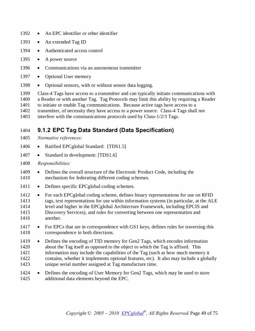
Copyright © 2005 – 2010 EPCglobal®, All Rights Reserved. Page 49 of 75
• An EPC identifier or other identifier 1392
• An extended Tag ID 1393
• Authenticated access control 1394
• A power source 1395
• Communications via an autonomous transmitter 1396
• Optional User memory 1397
• Optional sensors, with or without sensor data logging. 1398 Class-4 Tags have access to a transmitter and can typically initiate communications with 1399 a Reader or with another Tag. Tag Protocols may limit this ability by requiring a Reader 1400 to initiate or enable Tag communications. Because active tags have access to a 1401 transmitter, of necessity they have access to a power source. Class-4 Tags shall not 1402 interfere with the communications protocols used by Class-1/2/3 Tags. 1403
9.1.2 EPC Tag Data Standard (Data Specification) 1404 Normative references: 1405
• Ratified EPCglobal Standard: [TDS1.5] 1406
• Standard in development: [TDS1.6] 1407 Responsibilities: 1408
• Defines the overall structure of the Electronic Product Code, including the 1409 mechanism for federating different coding schemes. 1410
• Defines specific EPCglobal coding schemes. 1411
• For each EPCglobal coding scheme, defines binary representations for use on RFID 1412 tags, text representations for use within information systems (in particular, at the ALE 1413 level and higher in the EPCglobal Architecture Framework, including EPCIS and 1414 Discovery Services), and rules for converting between one representation and 1415 another. 1416
• For EPCs that are in correspondence with GS1 keys, defines rules for traversing this 1417 correspondence in both directions. 1418
• Defines the encoding of TID memory for Gen2 Tags, which encodes information 1419 about the Tag itself as opposed to the object to which the Tag is affixed. This 1420 information may include the capabilities of the Tag (such as how much memory it 1421 contains, whether it implements optional features, etc). It also may include a globally 1422 unique serial number assigned at Tag manufacture time. 1423
• Defines the encoding of User Memory for Gen2 Tags, which may be used to store 1424 additional data elements beyond the EPC. 1425
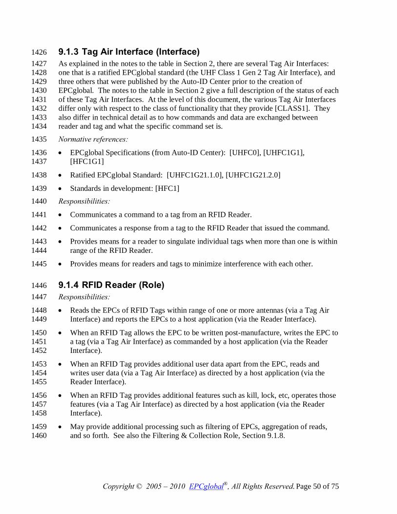
Copyright © 2005 – 2010 EPCglobal®, All Rights Reserved. Page 50 of 75
9.1.3 Tag Air Interface (Interface) 1426 As explained in the notes to the table in Section 2, there are several Tag Air Interfaces: 1427 one that is a ratified EPCglobal standard (the UHF Class 1 Gen 2 Tag Air Interface), and 1428 three others that were published by the Auto-ID Center prior to the creation of 1429 EPCglobal. The notes to the table in Section 2 give a full description of the status of each 1430 of these Tag Air Interfaces. At the level of this document, the various Tag Air Interfaces 1431 differ only with respect to the class of functionality that they provide [CLASS1]. They 1432 also differ in technical detail as to how commands and data are exchanged between 1433 reader and tag and what the specific command set is. 1434
Normative references: 1435
• EPCglobal Specifications (from Auto-ID Center): [UHFC0], [UHFC1G1], 1436 [HFC1G1] 1437
• Ratified EPCglobal Standard: [UHFC1G21.1.0], [UHFC1G21.2.0] 1438
• Standards in development: [HFC1] 1439
Responsibilities: 1440
• Communicates a command to a tag from an RFID Reader. 1441
• Communicates a response from a tag to the RFID Reader that issued the command. 1442
• Provides means for a reader to singulate individual tags when more than one is within 1443 range of the RFID Reader. 1444
• Provides means for readers and tags to minimize interference with each other. 1445
9.1.4 RFID Reader (Role) 1446 Responsibilities: 1447
• Reads the EPCs of RFID Tags within range of one or more antennas (via a Tag Air 1448 Interface) and reports the EPCs to a host application (via the Reader Interface). 1449
• When an RFID Tag allows the EPC to be written post-manufacture, writes the EPC to 1450 a tag (via a Tag Air Interface) as commanded by a host application (via the Reader 1451 Interface). 1452
• When an RFID Tag provides additional user data apart from the EPC, reads and 1453 writes user data (via a Tag Air Interface) as directed by a host application (via the 1454 Reader Interface). 1455
• When an RFID Tag provides additional features such as kill, lock, etc, operates those 1456 features (via a Tag Air Interface) as directed by a host application (via the Reader 1457 Interface). 1458
• May provide additional processing such as filtering of EPCs, aggregation of reads, 1459 and so forth. See also the Filtering & Collection Role, Section 9.1.8. 1460
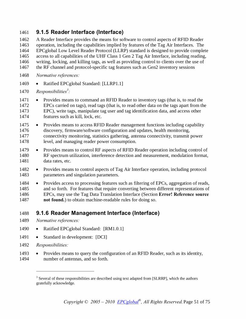
Copyright © 2005 – 2010 EPCglobal®, All Rights Reserved. Page 51 of 75
9.1.5 Reader Interface (Interface) 1461 A Reader Interface provides the means for software to control aspects of RFID Reader 1462 operation, including the capabilities implied by features of the Tag Air Interfaces. The 1463 EPCglobal Low Level Reader Protocol (LLRP) standard is designed to provide complete 1464 access to all capabilities of the UHF Class 1 Gen 2 Tag Air Interface, including reading, 1465 writing, locking, and killing tags, as well as providing control to clients over the use of 1466 the RF channel and protocol-specific tag features such as Gen2 inventory sessions 1467
Normative references: 1468
• Ratified EPCglobal Standard: [LLRP1.1] 1469 Responsibilities3: 1470
• Provides means to command an RFID Reader to inventory tags (that is, to read the 1471 EPCs carried on tags), read tags (that is, to read other data on the tags apart from the 1472 EPC), write tags, manipulate tag user and tag identification data, and access other 1473 features such as kill, lock, etc. 1474
• Provides means to access RFID Reader management functions including capability 1475 discovery, firmware/software configuration and updates, health monitoring, 1476 connectivity monitoring, statistics gathering, antenna connectivity, transmit power 1477 level, and managing reader power consumption. 1478
• Provides means to control RF aspects of RFID Reader operation including control of 1479 RF spectrum utilization, interference detection and measurement, modulation format, 1480 data rates, etc. 1481
• Provides means to control aspects of Tag Air Interface operation, including protocol 1482 parameters and singulation parameters. 1483
• Provides access to processing features such as filtering of EPCs, aggregation of reads, 1484 and so forth. For features that require converting between different representations of 1485 EPCs, may use the Tag Data Translation Interface (Section Error! Reference source 1486 not found.) to obtain machine-readable rules for doing so. 1487
9.1.6 Reader Management Interface (Interface) 1488 Normative references: 1489
• Ratified EPCglobal Standard: [RM1.0.1] 1490
• Standard in development: [DCI] 1491 Responsibilities: 1492
• Provides means to query the configuration of an RFID Reader, such as its identity, 1493 number of antennas, and so forth. 1494
3 Several of these responsibilities are described using text adapted from [SLRRP], which the authors gratefully acknowledge.
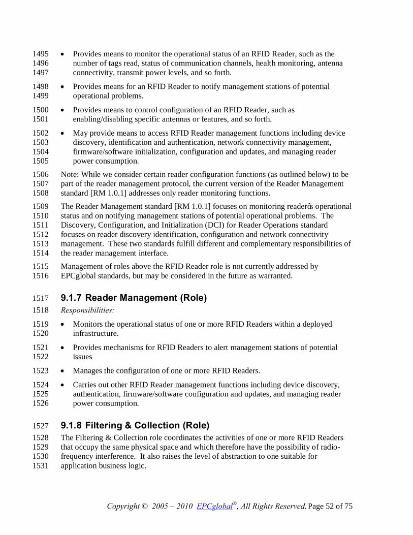
Copyright © 2005 – 2010 EPCglobal®, All Rights Reserved. Page 52 of 75
• Provides means to monitor the operational status of an RFID Reader, such as the 1495 number of tags read, status of communication channels, health monitoring, antenna 1496 connectivity, transmit power levels, and so forth. 1497
• Provides means for an RFID Reader to notify management stations of potential 1498 operational problems. 1499
• Provides means to control configuration of an RFID Reader, such as 1500 enabling/disabling specific antennas or features, and so forth. 1501
• May provide means to access RFID Reader management functions including device 1502 discovery, identification and authentication, network connectivity management, 1503 firmware/software initialization, configuration and updates, and managing reader 1504 power consumption. 1505
Note: While we consider certain reader configuration functions (as outlined below) to be 1506 part of the reader management protocol, the current version of the Reader Management 1507 standard [RM 1.0.1] addresses only reader monitoring functions. 1508 The Reader Management standard [RM 1.0.1] focuses on monitoring reader’s operational 1509 status and on notifying management stations of potential operational problems. The 1510 Discovery, Configuration, and Initialization (DCI) for Reader Operations standard 1511 focuses on reader discovery identification, configuration and network connectivity 1512 management. These two standards fulfill different and complementary responsibilities of 1513 the reader management interface. 1514 Management of roles above the RFID Reader role is not currently addressed by 1515 EPCglobal standards, but may be considered in the future as warranted. 1516
9.1.7 Reader Management (Role) 1517 Responsibilities: 1518
• Monitors the operational status of one or more RFID Readers within a deployed 1519 infrastructure. 1520
• Provides mechanisms for RFID Readers to alert management stations of potential 1521 issues 1522
• Manages the configuration of one or more RFID Readers. 1523
• Carries out other RFID Reader management functions including device discovery, 1524 authentication, firmware/software configuration and updates, and managing reader 1525 power consumption. 1526
9.1.8 Filtering & Collection (Role) 1527 The Filtering & Collection role coordinates the activities of one or more RFID Readers 1528 that occupy the same physical space and which therefore have the possibility of radio-1529 frequency interference. It also raises the level of abstraction to one suitable for 1530 application business logic. 1531
Copyright © 2005 – 2010 EPCglobal®, All Rights Reserved. Page 53 of 75
Responsibilities: 1532
• Receives raw tag reads from one or more RFID Readers. 1533
• Carries out processing to reduce the volume of EPC data, transforming raw tag reads 1534 into streams of events more suitable for application logic than raw tag reads. 1535 Examples of such processing include filtering (eliminating some EPCs according to 1536 their identities, such as eliminating all but EPCs for a specific object class), 1537 aggregating over time intervals (eliminating duplicate reads within that interval), 1538 grouping (e.g., summarizing EPCs within a specific object class), counting (reporting 1539 the number of EPCs rather than the EPC values themselves), and differential analysis 1540 (reporting which EPCs have been added or removed rather than all EPCs read). 1541
• Carries out an application’s requirements for writing, locking, killing, or otherwise 1542 operating upon tags by performing writes or other operations on one or more RFID 1543 Readers. 1544
• Determines which processing operations as described above may be delegated to the 1545 RFID Reader, and which must be performed by the Filtering & Collection role itself. 1546 Implicit in this responsibility is that the Filtering & Collection role knows the 1547 capabilities of associated RFID Readers. 1548
• Decodes raw tag values read from tags into URI representations defined by the Tag 1549 Data Standard, and conversely encodes URI representations into raw tag values for 1550 writing. May use the Tag Data Translation Interface (Section Error! Reference 1551 source not found.) to obtain machine-readable rules for doing so. 1552
• Maps between “logical reader names” and physical resources such as reader devices 1553 and/or specific antennas. 1554
• May provide decoding and encoding of non-EPC tag data in Tag user memory or 1555 other memory banks. 1556
• When the Filtering & Collection role is accessed by more than one client application, 1557 mediates between multiple client application requests for data when those requests 1558 involve the same set or overlapping subsets of RFID Readers. 1559
• May set and control the strategy for finding tags employed by RFID Readers. 1560
• May coordinate the operation of many readers and antennas within a local region in 1561 which RFID Readers may affect each other's operation; e.g., to minimize interference. 1562 For example, this role may control when specific readers are activated so that 1563 physically adjacent readers are not activated simultaneously. In another example, this 1564 role may make use of reader- or Tag Air Interface-specific features, such as the 1565 “sessions” feature of the UHF Class 1 Gen 2 Tag Air Interface, to minimize 1566 interference. 1567
The Filtering & Collection role has many responsibilities. The EPCglobal Architecture 1568 Framework currently provides standard interfaces to access some, but not all, of these 1569 responsibilities. Specifically: 1570
Copyright © 2005 – 2010 EPCglobal®, All Rights Reserved. Page 54 of 75
• The Filtering & Collection (ALE) 1.1 Interface (Section 9.1.9), provides standard 1571 interfaces that support use cases in which tags are inventoried, read, written or killed, 1572 in which the kill or lock passwords are maintained, and in which “user data” or TID 1573 memory on the tags is read or written. It also provides management interfaces for 1574 maintaining mappings between logical reader names and physical resources, for 1575 defining symbolic names for tag data fields, and for securing the use of the ALE 1576 interface by clients. 1577
• Other aspects of managing the Filtering & Collection role are not addressed by any 1578 EPCglobal standard. This includes controlling aspects of coordinating the activities 1579 of multiple readers to minimize interference, setting parameters that govern 1580 inventorying strategies, control over Tag Air Interface-specific features, and so on. 1581 Products of Solution Providers that implement the ALE 1.1 Interface may provide 1582 these features through vendor extensions to the ALE 1.1 Interface or through 1583 proprietary interfaces. 1584
9.1.9 Filtering & Collection (ALE) Interface (Interface) 1585 The Filtering & Collection (ALE) 1.1 Interface provides standard interfaces to the 1586 Filtering & Collection role. 1587
Normative references: 1588
• Ratified EPCglobal Standard: [ALE1.1.1] 1589 Responsibilities (“data plane”): 1590
• Provides means for one or more client applications to request EPC data from one or 1591 more Tag sources. 1592
• Provides means for one or more client applications to request that a set of operations 1593 be carried out on Tags accessible to one or more Tag sources. Such operations 1594 including writing, locking, and killing. 1595
• Insulates client applications from knowing how many readers/antennas, and what 1596 makes and models of readers are deployed to constitute a single, logical Tag source. 1597
• Provides declarative means for client applications to specify what processing to 1598 perform on EPC data, including filtering, aggregation, grouping, counting, and 1599 differential analysis, as described in Section 9.1.8. 1600
• Provides a means for client applications to request data or operations on demand 1601 (synchronous response) or as a standing request (asynchronous response). 1602
• Provides means for multiple client applications to share data from the same reader or 1603 readers, or to share readers’ access to Tags for carrying out other operations, without 1604 prior coordination between the applications. 1605
• Provides a standardized representation for client requests for EPC data and 1606 operations, and a standardized representation for reporting filtered, collected EPC 1607 data and the results of completed operations. 1608
Responsibilities (“control plane”): 1609
Copyright © 2005 – 2010 EPCglobal®, All Rights Reserved. Page 55 of 75
• Provides a means for client applications to query and configure the mapping between 1610 logical reader names as used in read/write requests and underlying physical resources 1611 such as RFID Readers. 1612
• Provides a means for client applications to configure symbolic names for Tag data 1613 fields. 1614
• Provides a means for management applications to secure client access to the ALE 1615 interface. 1616
9.1.10 EPCIS Capturing Application (Role) 1617 Responsibilities: 1618
• Recognizes the occurrence of EPC-related business events, and delivers these as 1619 EPCIS data. 1620
• May coordinate multiple sources of data in the course of recognizing an individual 1621 EPCIS event. Sources of data may include filtered, collected EPC data obtained 1622 through the Filtering & Collection Interface, other device-generated data such as bar 1623 code data, human input, and data gathered from other software systems. 1624
• May control the carrying out of actions in the physical environment, including writing 1625 RFID tags and controlling other devices. The EPCIS Capturing Application may use 1626 the Filtering & Collection Interface to carry out some of these responsibilities. 1627
9.1.11 EPCIS Capture Interface (Interface) 1628 Normative references: 1629
• Ratified EPCglobal standard: [EPCIS1.0.1] 1630 Responsibilities: 1631
• Provides a path for communicating EPCIS events generated by EPCIS Capturing 1632 Applications to other roles that require them, including EPCIS Repositories, internal 1633 EPCIS Accessing Applications, and Partner EPCIS Accessing Applications. 1634
9.1.12 EPCIS Query Interface (Interface) 1635 Normative references: 1636
• Ratified EPCglobal standard: [EPCIS1.0.1] 1637 Responsibilities: 1638
• Provides means whereby an EPCIS Accessing Application can request EPCIS data 1639 from an EPCIS Repository or an EPCIS Capturing Application, and the means by 1640 which the result is returned. 1641
• Provides a means for mutual authentication of the two parties. 1642
Copyright © 2005 – 2010 EPCglobal®, All Rights Reserved. Page 56 of 75
• Reflects the result of authorization decisions taken by the providing party, which may 1643 include denying a request made by the requesting party, or limiting the scope of data 1644 that is delivered in response. 1645
9.1.13 EPCIS Accessing Application (Role) 1646 Responsibilities: 1647
• Carries out overall enterprise business processes, such as warehouse management, 1648 shipping and receiving, historical throughput analysis, and so forth, aided by EPC-1649 related data. 1650
9.1.14 EPCIS Repository (Role) 1651 Responsibilities: 1652
• Records EPCIS-level events generated by one or more EPCIS Capturing 1653 Applications, and makes them available for later query by EPCIS Accessing 1654 Applications. 1655
9.1.15 Core Business Vocabulary (Data Specification) 1656 Normative references: 1657
• Ratified EPCglobal Standard: [CBV1.0] 1658
Responsibilities: 1659
• Provides standardized identifiers for use in EPCIS data to denote business steps, 1660 dispositions, and business transaction types. 1661
• Specifies syntax templates that end users may use to create identifiers for physical 1662 objects, locations, and business transactions, for use in EPCIS data. 1663
9.1.16 Drug Pedigree Messaging (Interface) 1664 In an attempt to help ensure only authentic pharmaceutical products are distributed 1665 through the supply chain, some regulatory agencies, have implemented or are considering 1666 provisions requiring a “pedigree” for drug products. Drug Pedigree Messaging is a data 1667 exchange interface intended to standardize the exchange of electronic pedigree 1668 documents. Although this standard is initially intended to meet regulatory requirements in 1669 certain U.S. states, this interface could be extended to meet the needs of other 1670 geographies and regulatory agencies in the future. Flexibility was built into the pedigree 1671 schema to allow for multiple interpretations of the existing and possible future, state, 1672 federal and even international laws. 1673 A pedigree is a certified record that contains information about each distribution of a 1674 prescription drug. It records the creation of an item by a pharmaceutical manufacturer, 1675 any acquisitions and transfers by wholesalers or re-packagers, and final transfer to a 1676 pharmacy or other entity administering or dispensing the drug. The pedigree contains 1677
Copyright © 2005 – 2010 EPCglobal®, All Rights Reserved. Page 57 of 75
product information, transaction information, distributor information, recipient 1678 information, and signatures. 1679
It is important to point out that the use of ePedigree schema does not require an EPC. The 1680 schema can be used even if products are not serialized. 1681
It is also important to note that a complete ePedigree document will not be created by 1682 issuing a query to the product network and assembling it from various components; 1683 rather, it will travel through the supply chain together with the product and gather the 1684 required digitally signed information along the way. 1685
Normative references: 1686
• Ratified EPCglobal Standard: [Pedigree1.0] 1687
Responsibilities: 1688
• Specifies a formal collection of XML schemas and associated usage guidelines under 1689 a Drug Pedigree Standard that can be adopted by members of the pharmaceutical 1690 supply chain. 1691
9.1.17 Object Name Service (ONS) Interface (Interface) 1692 Normative references: 1693
• Ratified EPCglobal Standard: [ONS1.0.1] 1694
Responsibilities: 1695
• Provides a means for looking up a reference to an EPCIS service or other service 1696 associated with an EPC. The list of services associated with an EPC is maintained by 1697 the EPC Manager for that EPC, and typically includes services operated by the 1698 organization that commissioned the EPC (often, but not always, the manufacturer; see 1699 Section 5.2). 1700
9.1.18 Local ONS (Role) 1701 Responsibilities: 1702
• Fulfills ONS lookup requests for EPCs within the control of the enterprise that 1703 operates the Local ONS; that is, EPCs for which the enterprise is the EPC Manager. 1704
See also the discussion of ONS in Section 7.3. 1705
9.1.19 ONS Root (EPC Network Service) 1706 Responsibilities: 1707
• Provides the authoritative source of data for the root of the hierarchical ONS lookup. 1708
• May provide the initial point of contact for ONS lookups, if the information is not 1709 available locally in the DNS resolver cache. 1710
Copyright © 2005 – 2010 EPCglobal®, All Rights Reserved. Page 58 of 75
• In most cases, delegates the remainder of the data authority and lookup operation to a 1711 Local ONS operated by the EPC Manager for the requested EPC. 1712
• May completely fulfill ONS requests in cases where there is no local ONS to which 1713 to delegate a lookup operation. 1714
• Provides a lookup service for 64-bit Manager Index values as required by earlier 1715 versions of the EPC Tag Data Standard. 1716
See also the discussion of ONS in Section 7.3. 1717
9.1.20 Manager Number Assignment (EPC Network Service) 1718 Responsibilities: 1719
• Ensures global uniqueness of EPCs by associating an Issuing Agency with each EPC 1720 scheme. 1721
• Ensures global uniqueness of EPCs by requiring each Issuing Agency to maintain 1722 uniqueness of EPC Manager Numbers assigned to End Users 1723
• Each Issuing Agency assigns new EPC Manager Numbers as required by End Users. 1724
9.1.21 Tag Data Translation (Interface and Data 1725 Specification) 1726
Normative references: 1727
• Ratified EPCglobal Standard: [TDT1.4] 1728 Responsibilities: 1729
• Provides machine-readable files that define how to translate between EPC encodings 1730 defined by the EPC Tag Data Standard (Section 9.1.2). EPCglobal provides these 1731 files for use by End Users, so that components of their infrastructure may 1732 automatically become aware of new EPC formats as they are defined. 1733
9.1.22 Discovery Services (EPC Network Service – In 1734 Development) 1735
At the time of writing, Discovery standards are still under technical development within 1736 EPCglobal and it is expected that the standard will not be ratified until late 2011. The 1737 EPCglobal Community has completed drafting requirements for the Discovery standards 1738 and services, following the Standards Development Process [SDP 1.5]. This has resulted 1739 in over sixty specific user requirements and fundamental principles for Discovery 1740 Services, organized in ten categories, covering Trust in the Network, Data Integrity & 1741 Confidentiality, Data Ownership & Management, Data in Discovery Services, Query 1742 Framework, Query Criteria, Identifiers and Pointers, End-to-end traceability and 1743 resilience, Scalability and Communication and Access Control. 1744
As a placeholder in this document, “Discovery Services” is labeled an EPC Network 1745 Service, but the final set of responsibilities may be addressed by a combination of EPC 1746
Copyright © 2005 – 2010 EPCglobal®, All Rights Reserved. Page 59 of 75
Network Services and EPCglobal Standards leading to services operated by End Users 1747 and independent Solution Providers. A fundamental principle in the Data Discovery 1748 requirements is that end users should have a choice of Discovery Service providers and 1749 that there should be mechanisms to allow independent auditing of Discovery Service 1750 operators, as well as mechanisms to allow users to migrate their data and access control 1751 policies from one Discovery Service provider to another. 1752
Discovery provides a means to locate EPCIS Services and other kinds of EPC-related 1753 information resources in the most general situations arising from multi-party supply 1754 chains or product lifecycles, in which several different organizations may have relevant 1755 data about an EPC but the identities of those organizations are not known in advance. 1756 The responsibilities of Discovery include the following. 1757 Responsibilities: 1758
• Facilitate visibility by providing a lookup mechanism to help find multiple sources of 1759 information related to serial-level unique identifiers (e.g., EPCs), particularly when 1760 that information is provided by multiple parties, is commercially sensitive and/or not 1761 published in the public domain. 1762
• The results of a Discovery Service query will typically provide a set of one or more 1763 URLs, each accompanied by an indication of the type of service to which they 1764 correspond; such service types may indicate EPCIS interfaces, web pages, web 1765 services, additional Discovery Services as well as other kinds of services. 1766
• Provides a means to allow parties to mutually identify and authenticate each other. 1767
• Provides a means to share information necessary for authorizing access to EPCIS 1768 service listings and EPCIS data. May provide a means to securely pass authorization 1769 rules among parties. 1770
• May provide a cache for selected EPCIS data for the purposes of resilient traceability 1771 or avoiding unnecessary cascading of queries. 1772
As described above, the Object Name Service (ONS) (Section 9.1.16) is a lookup service 1773 useful to find the address of the EPCIS service designated by the EPC Manager of an 1774 EPC. ONS does not address the issues of discovering the set of EPCIS data sources that 1775 may contain information about a particular EPC or set of EPCs. ONS and Discovery co-1776 exist and serve different roles in the EPCglobal architecture. 1777 Discovery does not address the storage, exchange, access authorization, or reporting of 1778 EPC observation data provided by EPCIS, except as noted above. However, because of 1779 the commercial sensitivity of serial-level data, particularly when it is held within a 1780 service to which multiple parties have access, a flexible and granular security framework 1781 will be developed for Discovery Services, wherever possible leveraging existing 1782 standards and state of the art technologies. The technical work group envisages a 1783 modular internal architecture for Discovery Services, providing the possibility of 1784 interfacing with external security services, where necessary. 1785
Copyright © 2005 – 2010 EPCglobal®, All Rights Reserved. Page 60 of 75
10 Summary of Unaddressed Issues 1786 As noted in Section 1 and throughout the document, there are technical needs that are 1787 believed to exist based on the analysis of known use cases, where those needs are not yet 1788 fully addressed by the EPCglobal Architecture Framework. In these cases, the 1789 architectural approach has not yet been finalized, and therefore work on developing 1790 standards or designing additional EPC Network Services has not yet begun, though 1791 architectural analysis is underway within the Architecture Review Committee. This 1792 section summarizes the known unaddressed issues, and will serve as a starting point for 1793 continued refinement of the EPCglobal Architecture Framework. 1794 The following list of issues is not intended to suggest the relative importance or priority 1795 of any issue. 1796
10.1 End User Authentication 1797 Section 7.1 also points out the need for end users to mutually authenticate each other 1798 when they are involved in EPCIS exchanges. It is desirable for this authentication to be 1799 as easy as possible for a end user to implement. In particular, it is undesirable if each end 1800 user has to make prior arrangements with every other end user that might be involved in a 1801 future EPCIS exchange; instead, it is better if each end user need only register once with 1802 a central authority and thereafter be able to mutually authenticate with any other end user. 1803
To achieve this goal, the X.509 authentication framework could be widely employed. 1804 The EPCglobal Certificate Profile standard for X.509 certificates [Cert2.0] has been 1805 developed to ensure that existing Internet standards for X.509 certificates can be 1806 deployed to authenticate Users, Services/Servers, Readers and Devices within the 1807 network. 1808
10.2 RFID Tag-level Security and Privacy 1809 Sections 3.7 and 3.8 discuss EPCglobal Architecture Framework goals of security and 1810 privacy. The UHF Class 1 Generation 2 Tag Air Interface supports specific RFID Tag 1811 features designed to further security and privacy goals. These features include a “kill” 1812 feature with an associated kill password, a “lock” feature, and an access control 1813 password. 1814 The EPCglobal Architecture Framework does not currently discuss how these features 1815 affect the architecture above the level of the ALE Interface, nor is there any architectural 1816 discussion of how the goals of security and privacy are addressed through these or other 1817 features. In particular, it is not clear how the passwords required to operate the “kill” and 1818 “lock” features are to be distributed through the network to reach the places where they 1819 are required. 1820 It should be noted that the “kill” and “lock” features are not a complete solution to 1821 privacy issues facing End Users. The EPCglobal Public Policy Steering Committee 1822 (PPSC) is responsible for creating and maintaining the EPCglobal Privacy Policy; readers 1823 should refer to PPSC documents for more information. 1824
Copyright © 2005 – 2010 EPCglobal®, All Rights Reserved. Page 61 of 75
10.3 “User Data” in RFID Tags 1825 The EPCglobal Architecture Framework discusses the use of RFID Tags that are used to 1826 hold an EPC associated with an object to which the tag is affixed. The UHF Class 1 1827 Generation 2 Tag Air Interface supports RFID Tags that contain additional “user data” 1828 besides the EPC. 1829
The EPCglobal Architecture Framework does not currently discuss how RFID Tag “user 1830 data” is to be exploited by applications. The ratified Reader Protocol, Low-Level Reader 1831 Protocol, and Application Level Events 1.1 standards provide access to user memory. 1832 The EPC Tag Data Standard 1.5 [TDS1.5] specifies how user memory is encoded on 1833 Gen2 tags. 1834
11 Data Protection in the EPCglobal Architecture 1835 Framework 1836
11.1 Overview 1837 This section describes and assesses the data protection and security mechanisms within 1838 the EPCglobal architecture. It provides general information for EPCglobal members 1839 wishing to gain a basic understanding of the data protection provisions within the 1840 EPCglobal Architecture Framework. 1841 This document does not contain a security analysis of the EPCglobal architecture or any 1842 systems based on the EPCglobal architecture. Security analysis requires not only detailed 1843 knowledge of the data communications standards, but also the relevant use cases, 1844 organizational process, and physical security mechanisms. Security analyses are left to 1845 the owners and users of the systems built using the EPCglobal Architecture Framework. 1846
Section 11.2 introduces security concepts. Section 11.3 describes the data protection 1847 mechanisms defined within the existing EPCglobal ratified standards. Section 0 1848 introduces the data protection methods that are being developed in evolving EPCglobal 1849 standards. 1850
11.2 Introduction 1851 Security is the process by which an organization or individual protects its valuable assets. 1852 In general, assets are protected to reduce the risk of an attack to acceptable levels, with 1853 the elimination of risk an often unrealizable extreme. Because the level of acceptable 1854 risk differs widely from application to application, there is no standard security solution 1855 that can apply to all systems. The EPCglobal architecture framework cannot be 1856 pronounced secure or insecure, nor can an individual standard or service. 1857
Data security is commonly subdivided into attributes: confidentiality, integrity, 1858 availability, and accountability. Data confidentiality is a property that ensures that 1859 information is not made available or disclosed to unauthorized individuals, entities, or 1860 processes. Data integrity is the property that data has not been changed, destroyed, or 1861 lost in an unauthorized or accidental manner during transport or storage. Data 1862 availability is a property of a system or a system resource being accessible and usable 1863
Copyright © 2005 – 2010 EPCglobal®, All Rights Reserved. Page 62 of 75
upon demand by an authorized system entity. Accountability is the property of a system 1864 (including all of its system resources) that ensures that the actions of a system entity may 1865 be traced uniquely to that entity, which can be held responsible for its actions 1866 [RFC2828]. 1867
Security techniques like encryption, authentication, digital signatures, and non-1868 repudiation services are applied to data to provide or augment the system attributes 1869 described above. 1870
As “security” cannot be evaluated without detailed knowledge of the entire system, we 1871 focus our efforts to describe the data protection methods within the EPCglobal Standards. 1872 That is, we describe the mechanisms that protect data when it is stored, shared and 1873 published within EPCglobal Standards and relate these mechanisms to the system 1874 attributes described above. 1875
11.3 Existing Data Protection Mechanisms 1876 This section summarizes the existing data protection mechanism within the standards and 1877 standards forming the EPCglobal Architecture Framework. 1878
11.3.1 Network Interfaces 1879 Many of the standards within the EPCglobal framework are based on network protocols 1880 that communicate EPC information over existing network technology including TCP/IP 1881 networks. This section summarizes the data protection mechanisms described within the 1882 interface standards. 1883 Some network standards within EPCglobal rely on Transport Layer Security [RFC2246] 1884 [RFC4346] as part of their underlying data protection mechanism. TLS provides a 1885 mechanism for the client and server to select cryptographic algorithms, exchange 1886 certificates to allow authentication of identity, and share key information to allow 1887 encrypted and validated data exchange. Mutual authentication within TLS is optional. 1888 Typically, TLS clients authenticate the server, but the client remains unauthenticated or is 1889 authenticated by non-TLS means once the TLS session is established. The protection 1890 provided by TLS depends critically on the cipher suite chosen by the client and server. A 1891 Cipher suite is a combination of cryptographic algorithms that define the methods of 1892 encryption, validation, and authentication. 1893 Some EPCglobal Standards rely on HTTPS (HTTP over TLS) for data protection. 1894 HTTPS [RFC2818] is a widely used standard for encrypting sensitive content for transfer 1895 over the World Wide Web. In common web browsers, the “security lock” shown on the 1896 task bar indicates that the transaction is secured using HTTPS. HTTPS is based on TLS 1897 (Transport Layer Security). A HTTPS client or endpoint acting as the initiator of the 1898 connection, initiates the TLS connection to the server, establishes a secure and 1899 authenticated connection and then commences the HTTP request. All HTTP data is sent 1900 as application data within the TLS connection and is protected by the encryption 1901 mechanism negotiated during the TLS handshake. The HTTPS specification defines the 1902 actions to take when the validity of the server is suspect. Using HTTPS, client and server 1903 can mutually authenticate using the mechanisms provided within TLS. However, 1904
Copyright © 2005 – 2010 EPCglobal®, All Rights Reserved. Page 63 of 75
another approach (and the one more frequently used) is for the client to authenticate the 1905 server within TLS, and then the server authenticates the client using HTTP-level 1906 password-based authentication carried out over the encrypted channel established by 1907 TLS. 1908
All of the data protection methods below are specified as optional behaviors of devices 1909 that comply with the relevant network interface standards. An enterprise must make the 1910 specific decision on whether these data protection mechanisms are valuable within their 1911 systems. 1912
11.3.1.1 Application Level Events 1.1 (ALE) 1913 The ALE 1.1 standard describes the interface to the Filtering and Collection Role within 1914 the EPCglobal architecture framework. It provides an interface to obtain filtered, 1915 consolidated EPC data from variety of EPC sources. For a complete description of the 1916 ALE 1.1 standard, see [ALE1.1.1]. 1917
ALE is specified in an abstract manner with the intention of allowing it to be carried over 1918 a variety of transport methods or bindings. The ALE 1.1 standard provides a SOAP 1919 [SOAP1.2] binding of the abstract protocol compliant with the Web Services 1920 Interoperability (WS-I) Basic Profile version 1.0 [WSI]. SOAP provides a method to 1921 exchange structured and typed information between peers. WS-I provides 1922 interoperability guidance for web services. SOAP is typically carried over HTTP and 1923 security based on HTTPS is permitted by the WS-I Basic Profile. ALE can utilize this 1924 SOAP/HTTPS binding for the ALE messages and responses to provide authentication 1925 and transport encryption. Authentication and encryption mechanisms together provide for 1926 confidentiality and integrity of the shared data. 1927
The ALE interface also provides a callback interface for events that are delivered 1928 asynchronously. . Several protocol bindings for callbacks are specified. The HTTPS 1929 binding of the callback interface provides for delivery of reports in XML via the HTTP 1930 protocol using POST operation secured via TLS. The HTTPS protocol provides link-level 1931 security, and optionally mutual authentication between an ALE implementation and its 1932 callback receivers. 1933
ALE 1.1 specifies an Access Control API over which administrative clients may define 1934 the access rights of other clients to use the facilities provided by the other ALE APIs. 1935 This API provides a standardized, role-based way to associate access control permissions 1936 with ALE client identifiers. This API can be used to restrict the operations that can be 1937 performed by clients (e.g. defining an event cycle) and also can restrict the data available 1938 to a client (e.g. restrict EPC data to a subset of the available logical readers). 1939
11.3.1.2 Reader Protocol 1.1 (RP) 1940 The current RP 1.1 standard provides a standard communication link between device 1941 providing services of a reader, and the device proving Filtering and Collection (F & C) of 1942 RFID data. For a complete description, see [RP1.1] 1943 The RP protocol supports the optional ability to encrypt and authenticate the 1944 communications link between these two devices when using certain types of 1945
Copyright © 2005 – 2010 EPCglobal®, All Rights Reserved. Page 64 of 75
communication links (transports). For example, HTTPS can be used as an alternative to 1946 HTTP when desiring a secure communication link between reader and host for Control 1947 Channels (initiated by a host to communicate with a reader) and/or Notification Channels 1948 (initiated by a reader to communicate with a host). This information is relevant to the 1949 authentication of the RP communications as the cipher suite provided requires only server 1950 authentication. The RP standard provides information and guidance for those desiring 1951 secure communication links when using other defined transports; see the RP standard for 1952 more details. 1953
11.3.1.3 Low Level Reader Protocol 1.1 (LLRP) 1954 The LLRP protocol supports the optional ability to encrypt and authenticate the 1955 communications link between these two devices using TLS. If X.509 certificates are used 1956 for authentication, LLRP requires certificates compliant with X.509 Certification Profile. 1957 Using TLS for LLRP Reader and Client communications provides the following 1958 protections: 1959
• Readers only talk to authorized clients 1960
• Clients only talk to authorized readers 1961
• No other party can read the LLRP messages (privacy protection) or inject/modify 1962 messages without being detected (integrity protection). 1963
Note that the strength of the protection depends on the negotiated cipher suites. 1964
11.3.1.4 Reader Management 1.0.1 (RM) 1965 The reader management standard describes wire protocol used by management software 1966 to monitor the operating status and health of EPCglobal compliant tag Readers. For a 1967 complete description, see [RM1.0.1]. 1968 RM divides its standard into three distinct layers: reader layer, messaging layer, and 1969 transport layer. The reader layer specifies the content and abstract syntax of messages 1970 exchanged between the Reader and Host. This layer is the heart of the Reader 1971 Management Protocol, defining the operations that Readers expose to monitor their 1972 health. The messaging layer specifies how messages defined in the reader layer are 1973 formatted, framed, transformed, and carried on a specific network transport. Any 1974 security services are supplied by this layer. The transport layer corresponds to the 1975 networking facilities provided by the operating system or equivalent. 1976 The current RM standard defines two implementations of the messaging layer or message 1977 transport bindings: XML and (Simple Network Management Protocol) SNMP. The XML 1978 binding follows the same conventions as RP described in section 11.3.1.2. The RM 1979 SNMP MIB is specified using SMIv2 allowing use of SNMP v2 [RFC1905] or SNMP v3 1980 [RFC3414]. SNMP v2c has weak authentication using community strings which are sent 1981 in plain-text within the SNMP messages. SNMP v2c contains no encryption 1982 mechanisms. SNMP v3 has strong authentication and encryption methods allowing 1983 optional authentication and optional encryption of protocol messages. 1984
Copyright © 2005 – 2010 EPCglobal®, All Rights Reserved. Page 65 of 75
11.3.1.5 EPC Information Services 1.0.1 (EPCIS) 1985 EPCIS provides EPC data sharing services between disparate applications both within 1986 and across enterprises. For a complete description of EPCIS, see [EPCIS1.0.1] 1987
EPCIS contains three distinct service interfaces, the EPCIS capture interface, the EPCIS 1988 query control interface, and the EPCIS query callback interface (The latter two interfaces 1989 are referred to collectively as the EPCIS Query Interfaces). The EPCIS capture interface 1990 and the EPCIS query interfaces both support methods to mutually authenticate the 1991 parties’ identities. 1992 Both the EPCIS capture interface and the EPCIS query interface allow implementations 1993 to authenticate the client’s identity and make appropriate authorization decisions based 1994 on that identity. In particular, the query interface specifies a number of ways that 1995 authorization decisions may affect the outcome of a query. This allows companies to 1996 make very fine-grain decisions about what data they want to share with their trading 1997 partners, in accordance with their business agreements. 1998 The EPCIS standard includes a binding for the EPCIS query interface (both the query 1999 control and query callback interfaces) using AS2 [RFC4130] for communication with 2000 external trading partners. AS2 provides for mutual authentication, data confidentiality 2001 and integrity, and non-repudiation. The EPCIS standard also includes WS-I compliant 2002 SOAP/HTTP binding for the EPCIS query control interface. This may be used with 2003 HTTPS to provide security. The EPCIS standard also includes an HTTPS binding for the 2004 EPCIS query callback interface. 2005
11.3.2 EPC Network Services 2006 EPCglobal and other organizations provide EPC Network Services. The following 2007 section describes the data protection methods employed by these services. 2008
11.3.2.1 Object Name Service 1.0 (ONS) 2009 The ONS service is based on the current internet Domain Name System (DNS). ONS 2010 provides authoritative lookup of information about an electronic identifier. See 2011 [ONS1.0.1] for a complete description. 2012
Users query the ONS server with an EPC (represented as a URI and translated into a 2013 domain name). ONS returns the requested data record which contains address 2014 information for services that may contain information about the particular EPC value. 2015 ONS does not provide information for individual EPCs; the lowest granularity of service 2016 is based on the object class of the EPC. ONS delivers only address information. The 2017 corresponding services are responsible for access control and authorization. 2018
The current Internet DNS standard provides a query interface. Users query the DNS 2019 server for information about a particular domain name, and the domain server returns 2020 information for the domain name in question. The system is a hierarchical set of DNS 2021 servers, culminating at the root DNS, serving addresses for the entire Internet 2022 community. As the DNS infrastructure is designed to provide address lookup service for 2023 all users of the internet, there is no encryption mechanism built into DNS/ONS. Any 2024
Copyright © 2005 – 2010 EPCglobal®, All Rights Reserved. Page 66 of 75
user wishing to gain Internet address information, can query DNS/ONS directly, hence 2025 the encryption of DNS traffic would have little or no benefit. 2026
New records are added to ONS manually, by electronic submission via a web interface. 2027 These submissions are protected by ACL (access control list) and by shared secret 2028 (password). 2029 For a complete security analysis of DNS, see [RFC3833]. 2030
11.3.2.2 Discovery Services 2031 Discovery Services are currently under development, and so the security mechanisms are 2032 still to be determined. Detailed user requirements have been captured and documented 2033 by the Data Discovery JRG, regarding Data Integrity & Confidentiality, Data Ownership 2034 and Access Control. The Data Discovery JRG took particular care to consider the 2035 perspectives of both the information provider (and the sensitivity of revealing the link 2036 between a specific EPC and a specific EPCIS resource) and also the sensitivity of the 2037 client's query to a Discovery Service (which itself may indicate which EPCs a specific 2038 company is handling). 2039
The technical work group for Discovery Services is using these requirements as the 2040 foundation for its work on the security framework for Discovery Services and, wherever 2041 possible, is leveraging established tried and tested best practices and existing open 2042 standards for security. 2043
11.3.2.3 Number Assignment 2044 Manager ID number assignment is provided as an EPC Network Service. These 2045 documents are provided as standard text files on a public web site operated by 2046 EPCglobal. Currently, these files contain only a list of the assigned manager numbers, 2047 and do not contain any information on the assignee of each ID. 2048
11.3.3 Tag Air Interfaces 2049 A Tag Air Interface specifies the Radio Frequency (RF) communications link between a 2050 reader device and an RFID tag. This interface is used to write and read data to and from 2051 an RFID tag. 2052
In general, transmitted RF energy is susceptible to eavesdropping or modification by any 2053 device within range of the intended receiver. To this end, each Tag Air Interface may 2054 have various countermeasures to protect the data transmitted across the interface specific 2055 to the application of the particular standard. 2056
11.3.3.1 UHF Class 1 Generation 2 (C1G2 or Gen2) 2057 The Class 1 Generation 2 Tag Air Interface standard specifies a UHF Tag Air Interface 2058 between readers and tags. The interface provides a mechanism to write and read data to 2059 and from an RFID tag respectively. A tag complying with the Gen2 standard can have up 2060 to four memory areas which store the EPC and EPC related data: EPC memory, User 2061
Copyright © 2005 – 2010 EPCglobal®, All Rights Reserved. Page 67 of 75
memory, TID memory, and reserved memory. For a complete description of the Gen2 2062 Tag Air Interface see [UHFC1G21.2.0]. 2063
The Gen2 Tag Air Interface, as its name professes, is the second generation of Class 1 2064 Tag Air Interfaces considered by EPCglobal. To this end, many of the security concerns 2065 of previous generation Tag Air Interfaces were well understood during the development 2066 of Gen2. 2067
The following describes the key data protection features of the Gen2 Tag Air Interface. 2068
11.3.3.1.1 Pseudonyms 2069 Class 1 Tags are passive devices that contain no power source. Tags communicate by 2070 backscattering energy sent by the interrogator or reader device. This phenomenon leads 2071 to an asymmetric link, where a very high energy signal is sent on the forward link from 2072 the interrogator to the tag. The tag responds by backscattering a very small portion of that 2073 energy on the reverse link, which can be detected by the interrogator, forming a bi-2074 directional half-duplex link. 2075 Depending on the regulatory region, antenna characteristics, and propagation 2076 environment, the high power forward link can be read hundreds to thousands of meters 2077 away from the interrogator source. The much lower power reverse link, often with only 2078 one millionth the power of the forward link, can typically be observed only within 10’s of 2079 meters of the RFID tag. 2080
To prevent the transmission of EPC information over the forward link, the Gen2 standard 2081 employs pseudonyms, or temporary identities for communication with tags. A 2082 pseudonym for a tag is used only within a single interrogator interaction. The 2083 interrogator uses this pseudonym for communication with the tag rather than the tag’s 2084 EPC or other tag data. The EPC is only presented in the interface on the backscatter link, 2085 limiting the range of eavesdropping to the range of backscatter communications. 2086 Eavesdroppers are still able to obtain EPC information during tag singulation, but cannot 2087 obtain this information from the high power forward link. 2088
Gen2 provides a select command which allows an interrogator to identify a subset of the 2089 total tag population for inventory. Using the select command requires the interrogator to 2090 transmit the forward link the bit pattern to match within the tag memory. Forward link 2091 transmission of this bit pattern may compromise the effectiveness of the pseudonym. 2092
11.3.3.1.2 Cover Coding 2093 For the same reasons described above, it may be undesirable to transmit non-EPC tag 2094 data on the forward link. To this end, Gen2 includes a technique called cover coding to 2095 obscure passwords and data transmitted to the tag on the forward link. Cover coding 2096 uses one-time-pads, random data backscattered by the tag upon request from the 2097 interrogator. Before sending data over the forward link, the interrogator requests a 2098 random number from the tag, and then uses this one-time-pad to encrypt a single word of 2099 data or password sent on the forward link. 2100
Copyright © 2005 – 2010 EPCglobal®, All Rights Reserved. Page 68 of 75
An observer of the forward communications link would not be able to decode data or 2101 passwords sent to the tag without first “guessing” the one-time-pad. Gen2 specifies that 2102 these pads can only be used a single time. 2103 An observer of the forward and reverse link would be able to observe the one-time-pads 2104 backscattered by the tag to the interrogator. This, in combination with the encryption 2105 method specified in Gen2 would allow this observer to decode all data and passwords 2106 sent on the forward link from the interrogator to the tag. 2107
Gen2 specifies an optional Block Write command which does not provide cover coding 2108 of the data sent over the forward link. Block write enables faster write operations at the 2109 expense of forward link security. 2110
11.3.3.1.3 Memory Locking 2111 Gen2 contains provisions to temporarily or permanently lock or unlock any of its 2112 memory banks. 2113
User, TID, and EPC memory may be write locked so that data stored in these memory 2114 banks cannot be overwritten. Reading of the TID, EPC and User memory banks are 2115 always permitted. There is no method to read-lock these memory banks. This memory 2116 can be temporarily or permanently locked or unlocked. Once permanently locked, 2117 memory cannot be written. When locked but not permanently locked, memory can be 2118 written, but only after the interrogator provides the 32-bit access password. 2119
Reserved memory currently specifies the location of two passwords: the access password 2120 and kill password. In order to prevent unauthorized users from reading these passwords, 2121 an interrogator can individually lock their contents. Locking of a password in reserved 2122 memory renders it un-writeable and un-readable. The read locking and write locking of 2123 password memory is not independent, e.g. memory cannot be write-locked without also 2124 being read-locked. A password can be temporarily or permanently locked or unlocked. 2125 Once permanently locked, memory cannot be written or read. When locked but not 2126 permanently locked, memory can be read and written only after the interrogator furnishes 2127 the 32-bit access password. 2128
11.3.3.1.4 Kill Command 2129 Gen2 contains a command to “kill” the tag. Killing a tag sets it to a state where it will 2130 never respond to the commands of an interrogator. To kill a tag, an interrogator must 2131 supply the 32-bit kill passwords. Tags with a zero-valued kill password cannot be killed. 2132 By perma-locking a zero valued kill password, tags can be rendered un-killable. By 2133 perma-unlocking the kill password, a tag can be rendered always killable. 2134
11.3.4 Data Format 2135
11.3.4.1 Tag Data Standard (TDS) 2136 The Tag Data Standard, currently Version 1.5, specifies the data format of the EPC 2137 information, both in its pure identity URI format and the binary format typically stored 2138
Copyright © 2005 – 2010 EPCglobal®, All Rights Reserved. Page 69 of 75
on an RFID tag. The TDS standard provides encodings for numbering schemes within an 2139 EPC, and does not provide encodings or standard representations for other types of data. 2140 For a complete description of the TDS standard, see [TDS1.5] 2141 RFID users are sometimes concerned with transmitting or backscattering EPC 2142 information that can directly infer the product or manufacturer of the product. Current 2143 Tag Air Interface standards do not provide mechanisms to secure the EPC data from 2144 unauthorized reading. 2145
TDS allows for the encoding of data types that contain manufacturer or company prefix, 2146 object class, and serial number. TDS also specifies encoding of formats that contain 2147 company prefix and serial number, but do not contain object class information. 2148
The TDS standard does not provide any encoding formats that standardize the encryption 2149 or obstruction of the manufacturer, product identification, or any other information stored 2150 on the RFID tag. 2151
11.3.5 Security 2152 Several EPCglobal Standards were created specifically to address security issues of 2153 shared data. 2154
11.3.6 EPCglobal X.509 Certificate Profile 2155 The authentication of entities (end users, services, physical devices) serves as the 2156 foundation of any security function incorporated into the EPCglobal Architecture 2157 Framework. The EPCglobal Architecture Framework allows the use of a variety of 2158 authentication technologies across its defined interfaces. It is expected, however, that the 2159 X.509 authentication framework will be widely employed. To this end, the EPCglobal 2160 Security 2 Working Group produced the EPCglobal X.509 Certificate profile. The 2161 certificate profile serves not to define new functionality, but to clarify and narrow 2162 functionality that already exists. For a complete description, see [Cert2.0] 2163
The certificate profile provides a minimum level of cryptographic security and defines 2164 and standardizes identification parameters for users, services/server and device. 2165
11.3.7 EPCglobal Electronic Pedigree 2166 EPCglobal electronic pedigree provides a standard, interoperable platform for supply 2167 chain partner compliance with state, regional and national drug pedigree laws. It 2168 provides flexible interpretation of existing and future pedigree laws. 2169
In the United States, current legislation in multiple states dictates the creation and 2170 updating of electronic pedigrees at each stop in the pharmaceutical supply chain. Each 2171 state law specifies the data content of the electronic pedigree and the digital signature 2172 standards but none of them specifies the actual format of the document. The need for a 2173 standard electronic document format that can be updated by each supply chain participant 2174 is what has driven the creation of the standard. 2175
Copyright © 2005 – 2010 EPCglobal®, All Rights Reserved. Page 70 of 75
The Standard does not identify exactly how pedigree documents must be transferred 2176 between trading partners. Any mechanism chosen must provide document immutability, 2177 non-repudiation and must be secure and authenticated. Although the scope of the 2178 standard focuses on the pedigree and pedigree envelope interchange formats, secure 2179 transmission relies on the recommendations for securing pedigree transmissions defined 2180 by the HLS Information Work Group. 2181
12 References 2182 [ALE1.1.1] EPCglobal, “The Application Level Events (ALE) Specification, Version 2183 1.1; Part 1: Core Specification” EPCglobal Ratified Standard, March 2009, 2184 http://www.epcglobalinc.org/standards/ale/ale_1_1_1-standard-core-20090313.pdf. 2185
[CBV1.0] EPCglobal, “Core Business Vocabulary Specification, Version 1.0,” 2186 EPCglobal Ratified Standard, October 2010, 2187 http://www.epcglobalinc.org/standards/cbv/cbv_1_0-standard-20101013.pdf. 2188
[Cert2.0] EPCglobal, “EPCglobal Certificate Profile 2.0,” EPCglobal Ratified Standard, 2189 August 2010, http://www.epcglobalinc.org/standards/cert/cert_2_0-standard-2190 20100810.pdf. 2191
[CLASS1] Engels, D.W. and Sarma S.E, “Standardization Requirements within the 2192 RFID Class Structure Framework”, MIT Auto-ID Labs Technical Report, January 2005. 2193
[EPCIS1.0.1] EPCglobal, “EPC Information Services (EPCIS) Version 1.0.1 2194 Specification,” EPCglobal Ratified Standard, September 2007, 2195 http://www.epcglobalinc.org/standards/epcis/epcis_1_0_1-standard-20070921.pdf. 2196 [GS1GS] GS1, “General Specifications v7.1,” January 2007, 2197 http://www.gs1uk.org/EANUCC/ 2198
[HFC1G1] MIT Auto-ID Center, “13.56 MHz ISM Band Class 1Radio Frequency 2199 Identification Tag Interface Specification: Candidate Recommendation, Version 1.0.0,” 2200 February 2003, http://www.epcglobalinc.org/standards_technology/Secure/v1.0/HF-2201 Class1.pdf. 2202 [HFC1] EPCglobal, “EPC Radio-Frequency Identity Protocols EPC Class-1 HF RFID 2203 Air Interface Protocol for Communications at 13.56MHz,Version 2.0.3,” EPCglobal 2204 Proposed Specification, June, 2010. 2205
[ISO19762-3] ISO/IEC, “Information technology — Automatic identification and data 2206 capture (AIDC) techniques — Harmonized vocabulary — Part 3: Radio frequency 2207 identification (RFID),” ISO/IEC International Standard, March, 2005. 2208 [LLRP1.1] EPCglobal, “EPCglobal Low Level Reader Protocol (LLRP), Version 1.1”, 2209 Ratified EPCglobal Standard, October 2010, 2210 http://www.epcglobalinc.org/standards/llrp/llrp_1_1-standard-20101013.pdf. 2211 [ONS1.0.1] EPCglobal, “EPCglobal Object Naming Service (ONS), Version 1.0.1,” 2212 EPCglobal Ratified Standard, May 2008, 2213 http://www.epcglobalinc.org/standards/ons/ons_1_0_1-standard-20080529.pdf. 2214
Copyright © 2005 – 2010 EPCglobal®, All Rights Reserved. Page 71 of 75
[Pedigree1.0] EPCglobal, “Pedigree Ratified Standard, Version 1.0,” EPCglobal Ratified 2215 Standard, January, 2007, http://www.epcglobalinc.org/standards/pedigree/pedigree_1_0-2216 standard-20070105.pdf. 2217 [RFC1034] P. V. Mockapetris, “Domain names – concepts and facilities.” RFC1034, 2218 November 1987, http://www.ietf.org/rfc/rfc1034. 2219 [RFC1035] P. V. Mockapetris, “Domain names – implementation and specification.” 2220 RFC1035, November 1987, http://www.ietf.org/rfc/rfc1035. 2221
[RFC1905] J. Case, K. McCloghrie, M. Rose, S. Waldbusser, “Protocol Operations for 2222 Version 2 of the Simple Network Management Protocol (SNMPv2)”, RFC 1905, January 2223 1996. 2224 [RFC2246] T. Dierks, “The TLS Protocol Version 1.0”, RFC 2246, January 1999, 2225 http://www.ietf.org/rfc/rfc2246. 2226 [RFC2818] P. Rescorla, “HTTP Over TLS”, RFC 2818, May 2000, 2227 http://www.ietf.org/rfc/rfc2818. 2228 [RFC2828] R. Shirey, “Internet Security Glossary”, RFC 2828, May 2000, 2229 http://www.ietf.org/rfc/rfc2828. 2230 [RFC3414] U. Blumenthal, “User-based Security Model (USM) for version 3 of the 2231 Simple Network Management Protocol (SNMPv3)”, RFC 3414, December 2002 2232 http://www.ietf.org/rfc/rfc3414. 2233 [RFC3833] D Atkins, “Threat Analysis of the Domain Name System (DNS)”, RFC 3833, 2234 August 2004, http://www.ietf.org/rfc/rfc3833. 2235 [RFC4130] D. Moberg and R. Drummond, “MIME-Based Secure Peer-to-Peer Business 2236 Data Interchange Using HTTP, Applicability Statement 2 (AS2),” RFC4130, July 2005, 2237 http://www.ietf.org/rfc/rfc4130. 2238 [RFC4346] T. Dierks, “The Transport Layer Security (TLS) Protocol Version 1.1”, RFC 2239 4346, April 2006, http://www.ietf.org/rfc/rfc4346. 2240 [RM1.0.1] “Reader Management 1.0.1,” EPCglobal Ratified Standard, May 2007, 2241 http://www.epcglobalinc.org/standards/rm/rm_1_0_1-standard-20070531.pdf. 2242
[DCI] EPCglobal, “Discovery, Configuration, and Initialization (DCI) for Reader 2243 Operations”, EPCglobal Candidate Specification, August 2007. 2244
[SDP1.5] EPCglobal, “EPCglobal Standards Development Process Version 1.5,” 2245 EPCglobal publication, February 2009, 2246 http://www.epcglobalinc.org/standards/sdp/EPCglobalSDP_1_5-Specification-2247 20090227.pdf. 2248
[SLRRP] P. Krishna, D. Husak, “Simple Lightweight RFID Reader Protocol,” IETF 2249 Internet Draft, June 2005. 2250
[SOAP1.2] M. Gudgin, M. Hadley, N. Mendelsohn, J-J. Moreau, H. F. Nielsen, “SOAP 2251 Version 1.2,” W3C Recommendation, June 2003, http://www.w3.org/TR/soap12. 2252
[TDS1.5] EPCglobal, “EPCglobal Tag Data Standards Version 1.5,” EPCglobal Ratified 2253 Standard, August 2010, http://www.epcglobalinc.org/standards/tds/tds_1_5-standard-2254 20100818.pdf. 2255
Copyright © 2005 – 2010 EPCglobal®, All Rights Reserved. Page 72 of 75
[TDS1.6] EPCglobal, “EPCglobal Tag Data Standards Version 1.6,” EPCglobal 2256 Standard in development. 2257
[TDT1.4] EPCglobal, “EPCglobal Tag Data Translation (TDT) 1.4,” EPCglobal 2258 Ratified Standard, June 2009, http://www.epcglobalinc.org/standards/tdt/tdt_1_4-2259 standard-20090610.pdf. 2260 [UHFC0] MIT Auto-ID Center, “Draft protocol specification for a 900 MHz Class 0 2261 Radio Frequency Identification Tag,” EPCglobal Specification, Februrary 2003, 2262 http://www.epcglobalinc.org/standards_technology/Secure/v1.0/UHF-class0.pdf. 2263
[UHFC1G1] MIT Auto-ID Center, “860MHz–930MHz Class I Radio Frequency 2264 Identification Tag Radio Frequency & Logical Communication Interface Specification 2265 Candidate Recommendation, Version 1.0.1,” EPCglobal Specification, November 2002, 2266 http://www.epcglobalinc.org/standards_technology/Secure/v1.0/UHF-class1.pdf. 2267
[UHFC1G21.1.0] EPCglobal, “EPC™ Radio-Frequency Identity Protocols Class-1 2268 Generation-2 UHF RFID Protocol for Communications at 860 MHz – 960 MHz Version 2269 1.1.0,” EPCglobal Ratified Standard, October 2007, 2270 http://www.epcglobalinc.org/standards/uhfc1g2/uhfc1g2_1_1_0-standard-20071017.pdf. 2271
[UHFC1G21.2.0] EPCglobal, “EPC™ Radio-Frequency Identity Protocols Class-1 2272 Generation-2 UHF RFID Protocol for Communications at 860 MHz – 960 MHz Version 2273 1.2.0,” EPCglobal Ratified Standard, May 2008, 2274 http://www.epcglobalinc.org/standards/uhfc1g2/uhfc1g2_1_2_0-standard-20080511.pdf. 2275
[WSI] K. Ballinger, D. Ehnebuske, M. Gudgin, M. Nottingham, P. Yendluri, “Basic 2276 Profile Version 1.0,” WS-I Final Material, April 2004, http://www.ws-2277 i.org/Profiles/BasicProfile-1.0-2004-04-16.html 2278
13 Glossary 2279 This section provides a summary of terms used within this document. For fuller 2280 definitions of these terms, please consult the relevant sections of the document. See also 2281 the whole of Section 9, which defines all roles and interfaces within the EPCglobal 2282 Architecture Framework. 2283
Term Section Meaning
EPCglobal Architecture Framework
1 A collection of interrelated standards (“EPCglobal Standards”), together with services operated by EPCglobal, its delegates, and others (“EPC Network Services”), all in service of a common goal of enhancing business flows and computer applications through the use of Electronic Product Codes (EPCs).
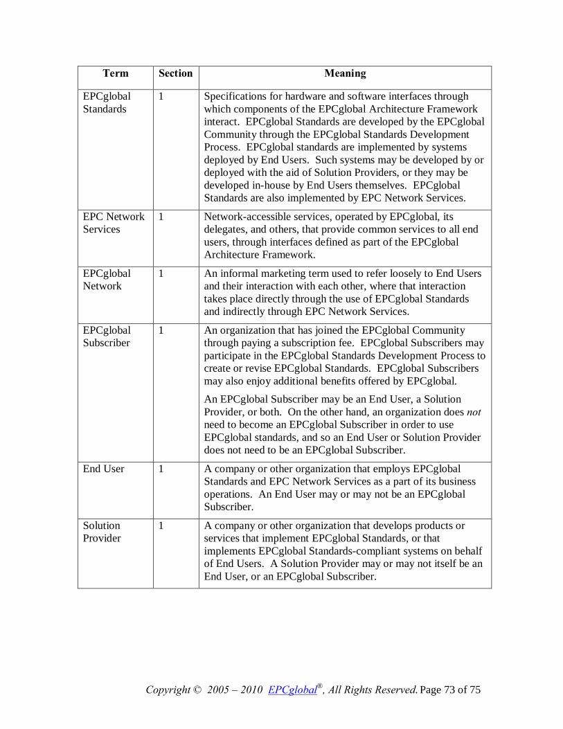
Copyright © 2005 – 2010 EPCglobal®, All Rights Reserved. Page 73 of 75
Term Section Meaning
EPCglobal Standards
1 Specifications for hardware and software interfaces through which components of the EPCglobal Architecture Framework interact. EPCglobal Standards are developed by the EPCglobal Community through the EPCglobal Standards Development Process. EPCglobal standards are implemented by systems deployed by End Users. Such systems may be developed by or deployed with the aid of Solution Providers, or they may be developed in-house by End Users themselves. EPCglobal Standards are also implemented by EPC Network Services.
EPC Network Services
1 Network-accessible services, operated by EPCglobal, its delegates, and others, that provide common services to all end users, through interfaces defined as part of the EPCglobal Architecture Framework.
EPCglobal Network
1 An informal marketing term used to refer loosely to End Users and their interaction with each other, where that interaction takes place directly through the use of EPCglobal Standards and indirectly through EPC Network Services.
EPCglobal Subscriber
1 An organization that has joined the EPCglobal Community through paying a subscription fee. EPCglobal Subscribers may participate in the EPCglobal Standards Development Process to create or revise EPCglobal Standards. EPCglobal Subscribers may also enjoy additional benefits offered by EPCglobal. An EPCglobal Subscriber may be an End User, a Solution Provider, or both. On the other hand, an organization does not need to become an EPCglobal Subscriber in order to use EPCglobal standards, and so an End User or Solution Provider does not need to be an EPCglobal Subscriber.
End User 1 A company or other organization that employs EPCglobal Standards and EPC Network Services as a part of its business operations. An End User may or may not be an EPCglobal Subscriber.
Solution Provider
1 A company or other organization that develops products or services that implement EPCglobal Standards, or that implements EPCglobal Standards-compliant systems on behalf of End Users. A Solution Provider may or may not itself be an End User, or an EPCglobal Subscriber.
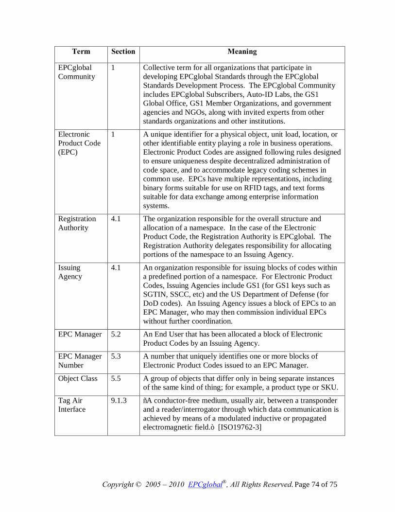
Copyright © 2005 – 2010 EPCglobal®, All Rights Reserved. Page 74 of 75
Term Section Meaning
EPCglobal Community
1 Collective term for all organizations that participate in developing EPCglobal Standards through the EPCglobal Standards Development Process. The EPCglobal Community includes EPCglobal Subscribers, Auto-ID Labs, the GS1 Global Office, GS1 Member Organizations, and government agencies and NGOs, along with invited experts from other standards organizations and other institutions.
Electronic Product Code (EPC)
1 A unique identifier for a physical object, unit load, location, or other identifiable entity playing a role in business operations. Electronic Product Codes are assigned following rules designed to ensure uniqueness despite decentralized administration of code space, and to accommodate legacy coding schemes in common use. EPCs have multiple representations, including binary forms suitable for use on RFID tags, and text forms suitable for data exchange among enterprise information systems.
Registration Authority
4.1 The organization responsible for the overall structure and allocation of a namespace. In the case of the Electronic Product Code, the Registration Authority is EPCglobal. The Registration Authority delegates responsibility for allocating portions of the namespace to an Issuing Agency.
Issuing Agency
4.1 An organization responsible for issuing blocks of codes within a predefined portion of a namespace. For Electronic Product Codes, Issuing Agencies include GS1 (for GS1 keys such as SGTIN, SSCC, etc) and the US Department of Defense (for DoD codes). An Issuing Agency issues a block of EPCs to an EPC Manager, who may then commission individual EPCs without further coordination.
EPC Manager 5.2 An End User that has been allocated a block of Electronic Product Codes by an Issuing Agency.
EPC Manager Number
5.3 A number that uniquely identifies one or more blocks of Electronic Product Codes issued to an EPC Manager.
Object Class 5.5 A group of objects that differ only in being separate instances of the same kind of thing; for example, a product type or SKU.
Tag Air Interface
9.1.3 “A conductor-free medium, usually air, between a transponder and a reader/interrogator through which data communication is achieved by means of a modulated inductive or propagated electromagnetic field.” [ISO19762-3]
Copyright © 2005 – 2010 EPCglobal®, All Rights Reserved. Page 75 of 75
14 Acknowledgements 2284 The following former members of the EPCglobal Architecture Review Committee 2285 contributed to earlier versions of this document: 2286 Greg Allgair (formerly of EPCglobal), Leo Burstein (formerly of Gillette), Bryan 2287 Rodrigues (formerly of CVS), Johannes Schmidt (formerly of Kraft), Chuck Schramek 2288 (formerly of EPCglobal), Roger Stewart (formerly of Intelleflex and AWiD), 2289
The authors would like to thank the following persons and organizations for their 2290 comments on earlier versions of this document: 2291
John Anderla (Kimberly Clark), Chet Birger (ConnecTerra), Judy Bueg (Eastman 2292 Kodak), Curt Carrender (Alien Technogies), Chris Diorio (Impinj), Andreas Füßler (GS1 2293 Europe), Lim Joo Ghee (Institute for Infocomm Research), Graham Gillen (VeriSign), 2294 Sue Hutchinson (EPCglobal), Osamu Inoue (EPCglobal Japan), P. Krishna (Reva 2295 Systems), Shinichi Nakahara (NTT), Mike O’Shea (Kimberly Clark), Andrew Osborne 2296 (GS1 Technical Steering Team), Hidenori Ota (Fujitsu), Tom Pounds (Alien 2297 Technologies), Steve Rehling (Procter & Gamble), Steve Smith (Alien Technologies), 2298 Suzanne Stuart-Smith (GS1 UK), Hiroyasu Sugano (Fujitsu), Hiroki Tagato (NEC), Neil 2299 Tan (UPS), Joseph Tobolski (Accenture), Nicholas Tsougas (US Defense Logistics 2300 Agency), Mitsuo Tsukada (NTT), Shashi Shekhar Vempati (Infosys), Ulrich Wertz (MGI 2301 METRO Group), Gerd Wolfram (MGI METRO Group), and Ochi Wu (CODEplus). 2302