Embed Size (px)
Citation preview
April 19, 2007EVLA Update 1
The EVLA ProjectAn Update
Rick PerleyNational Radio Astronomy Observatory
April 19, 2007EVLA Update 2
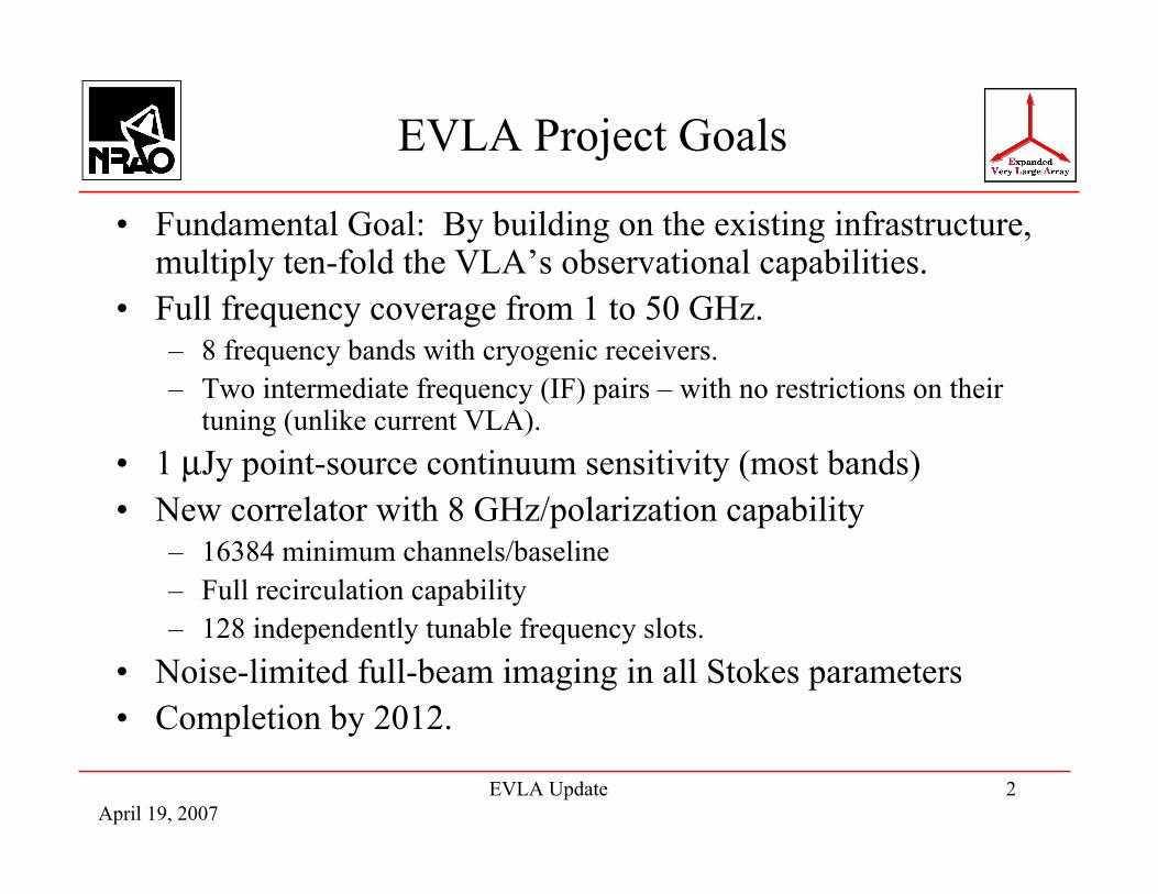
EVLA Project Goals
• Fundamental Goal: By building on the existing infrastructure,multiply ten-fold the VLA’s observational capabilities.
• Full frequency coverage from 1 to 50 GHz.– 8 frequency bands with cryogenic receivers.– Two intermediate frequency (IF) pairs – with no restrictions on their
tuning (unlike current VLA).• 1 µJy point-source continuum sensitivity (most bands)• New correlator with 8 GHz/polarization capability
– 16384 minimum channels/baseline– Full recirculation capability– 128 independently tunable frequency slots.
• Noise-limited full-beam imaging in all Stokes parameters• Completion by 2012.
April 19, 2007EVLA Update 3
Frequency - Resolution Coverage
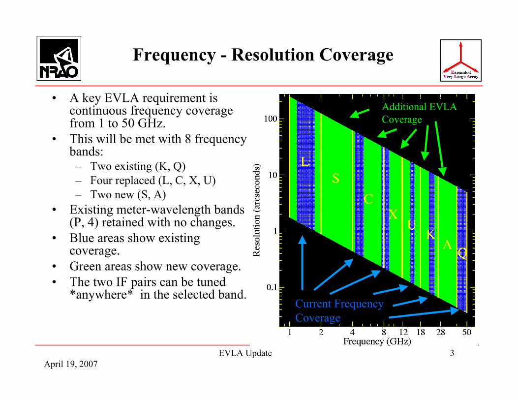
• A key EVLA requirement iscontinuous frequency coveragefrom 1 to 50 GHz.
• This will be met with 8 frequencybands:– Two existing (K, Q)– Four replaced (L, C, X, U)– Two new (S, A)
• Existing meter-wavelength bands(P, 4) retained with no changes.
• Blue areas show existingcoverage.
• Green areas show new coverage.• The two IF pairs can be tuned
*anywhere* in the selected band.Current Frequency Coverage
Additional EVLA Coverage
April 19, 2007EVLA Update 4
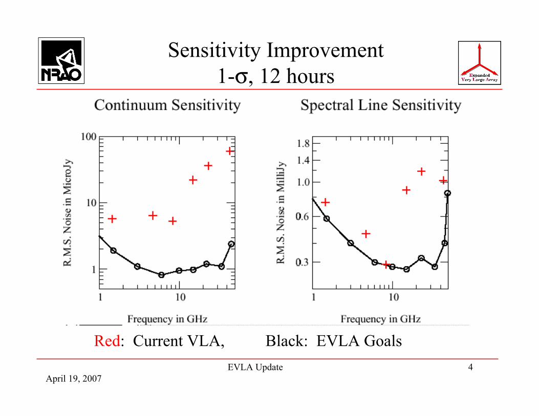
Sensitivity Improvement1-σ, 12 hours
Red: Current VLA, Black: EVLA Goals

April 19, 2007EVLA Update 5
EVLA-I Performance Goals
100%
0.12 Hz2 MHz
4,194,304
16,384 8 GHz
1 µJy
EVLA
522%(Log) Frequency Coverage (1 – 50 GHz)
3180381 HzFinest frequency resolution2550 MHzCoarsest frequency resolution
8192512Maximum number of frequency channels
102416# of frequency channels at max. bandwidth800.1 GHzMaximum BW in each polarization
1010 µJyPoint Source Sensitivity (1-σ, 12 hours)
FactorVLAParameter
The EVLA’s performance is vastly better than the VLA’s:
The cost to the NSF for this >10-fold improvement is $57M – about 1/3 the cost of the original VLA.

April 19, 2007EVLA Update 6
What is the EVLA Not Doing?(or, what happened to Phase II?)
• Expanding to provide 10 times the current best resolution (theNew Mexico Array).– Lost: A ~few Kelvin brightness sensitivity at milliarcsecond resolution
capability provided by the full EVLA.• A super-compact configuration, for low surface brightness
imaging (the ‘E’ configuration).– This ~$6M component could easily and quickly be done as a
standalone project. (Lost: 10 µK brightness sensitivity on 12arcsecond scale at 34 GHz).
• A sub-1 GHz facility. The VLA’s optics system makes it verydifficult to implement an efficient wide-band low-frequencycapability.– All proposed methods to do this require extensive design and
development – for which we have no budget.

April 19, 2007EVLA Update 7
The Eight Frequency Bands
8 x 4 x 38 x 4 x 38 x 4 x 36 x 4 x 34 x 4 x 34 x 4 x 34 x 2 x 8
2 x 2GS/s x 8bits
Digitization
2x8.3060 - 9540-502x8.455026.5-402x8.554518-26.52x6.653512-182x4.65348-122x4.60244-82x2.60252-42x1.43281-2
IF BW(GHz)
ApertureEffic. (%)
SystemTemp (K)
Band (GHz)
Blue = System tested and in place, or under installation. Green = Prototypes to be tested in 2007 or 2008.Red = Deferred to end of project
April 19, 2007EVLA Update 8
EVLA Feed System
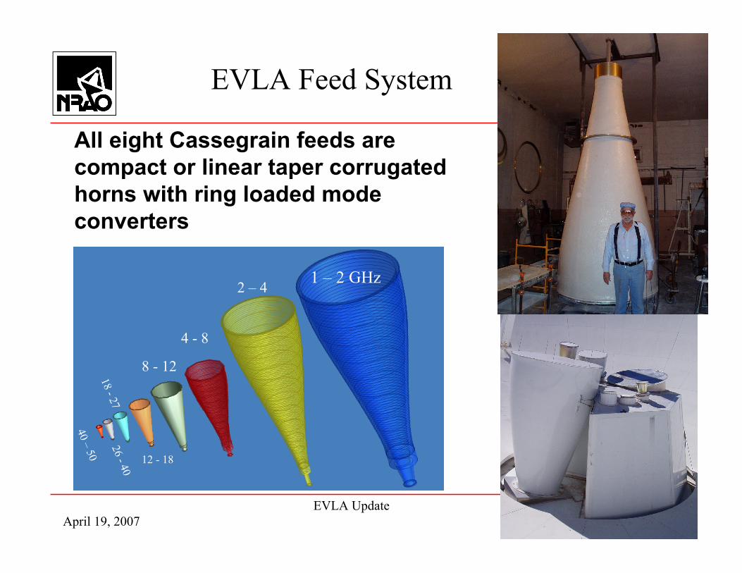
All eight Cassegrain feeds arecompact or linear taper corrugatedhorns with ring loaded modeconverters
1 – 2 GHz2 – 4
4 - 8
8 - 12
12 - 18
18 - 2726 - 40
40 – 50
April 19, 2007EVLA Update 9
Today’s EVLA Status!
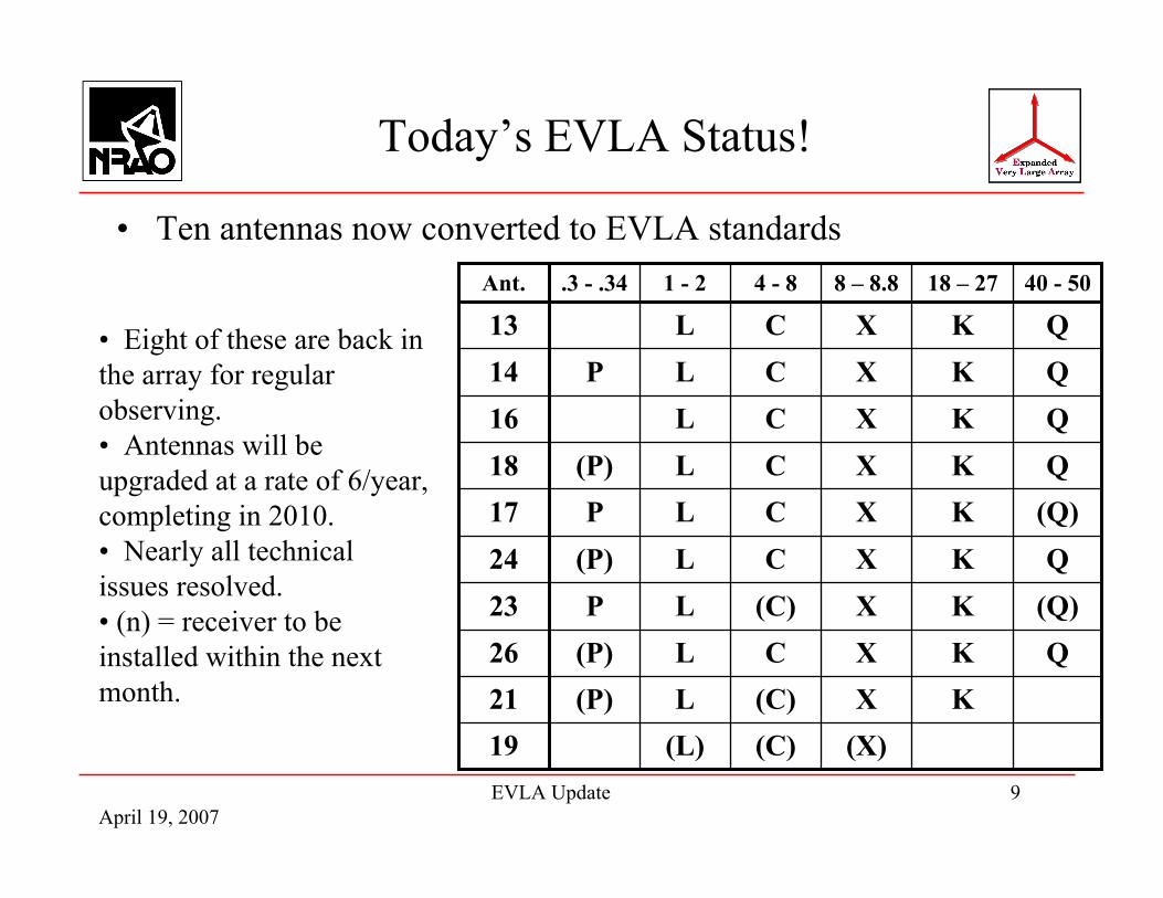
• Ten antennas now converted to EVLA standards40 - 5018 – 278 – 8.84 - 81 - 2.3 - .34Ant.
QKXCL(P)26KX(C)L(P)21
(Q)KXCLP17
(Q)KX(C)LP23
(X)(C)(L)19
QKXCL(P)24
QKXCL(P)18QKXCL16QKXCLP14QKXCL13• Eight of these are back in
the array for regularobserving.• Antennas will beupgraded at a rate of 6/year,completing in 2010.• Nearly all technicalissues resolved.• (n) = receiver to beinstalled within the nextmonth.

April 19, 2007EVLA Update 10
New Capabilities Timescale
• The old correlatorwill be employeduntil the WIDARcorrelator achievesfull 27-antennacapability – mid2009.
• Old correlator’slimitations remain:– 50 MHz BW– 16 to 512 channels
• Full band tuningavailable now, onschedule shownhere.
April 19, 2007EVLA Update 11
4 and P Bands(73.0 – 74.6, 300 – 340 MHz)
• No change in tuning or antenna sensitivity.• The n*100 kHz comb lines are gone!• All other internally generated combs are gone (we
think!)• Deployment of these bands were delayed for some
time by design issues which are now resolved.• Outfitting will catch up by summer, ready for A-
configuration.
April 19, 2007EVLA Update 12
L-Band1.0 – 2.0 GHz
• Currently deploying an ‘interim receiver’, providing1.2 – 2.0 GHz tuning.
• Final system (full 1.0 – 2.0 GHz) awaits final testingand production of the new OMT.
• Unexpected good news: Virtually no RFI in newlyavailable spectral zone: 1740 – 2000 MHz.
• Efficiency of new system 40 – 46%.– Compared to ~50% for VLA L-band feed.
• Tsys below 30K.• Spillover contribution much reduced at low elevation.
April 19, 2007EVLA Update 13
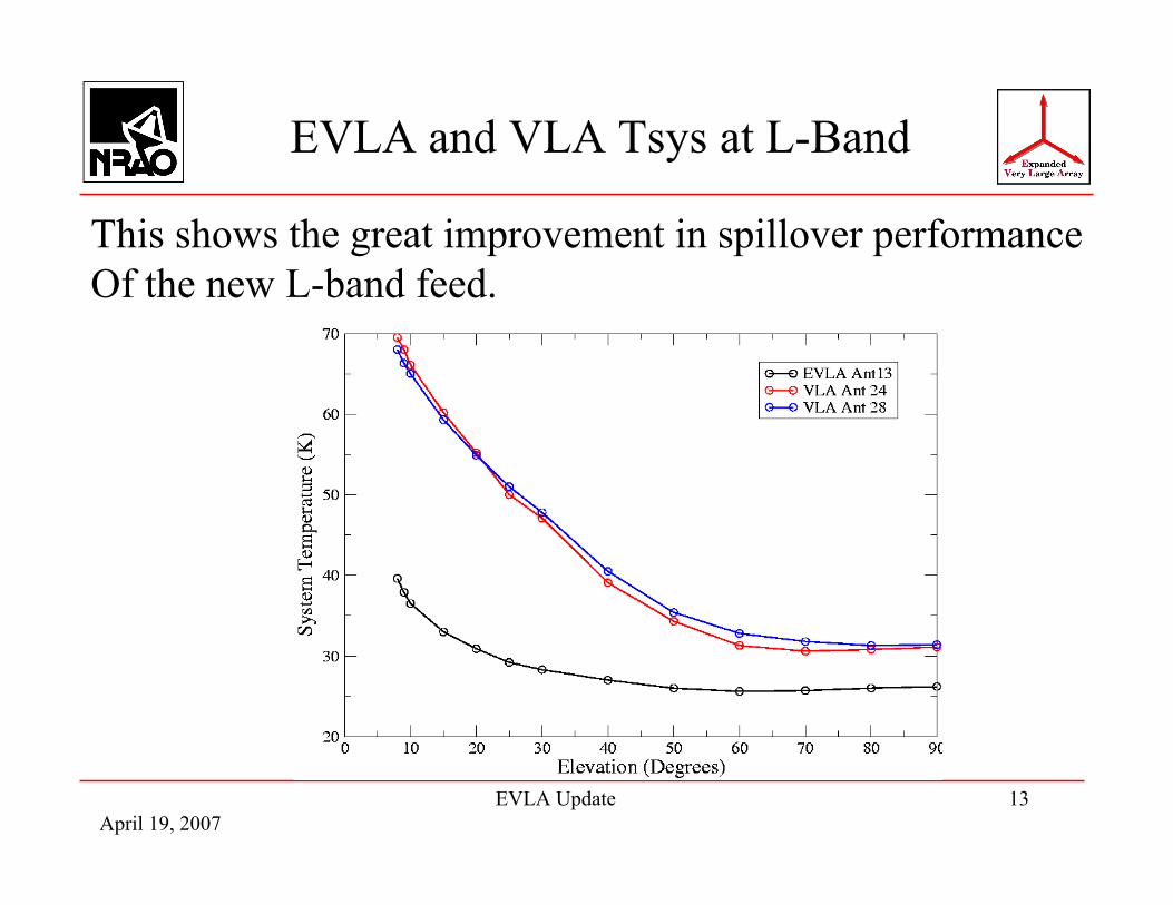
EVLA and VLA Tsys at L-Band
This shows the great improvement in spillover performanceOf the new L-band feed.

April 19, 2007EVLA Update 14
L-Band OMT
• New L-Band Horn/OMT nowinstalled on antenna 14.
• Designed to give 1 – 2 GHzhigh efficiency, goodpolarization.
Horn
OMT (inside cryo)
Receiver

April 19, 2007EVLA Update 15
S-Band2 – 4 GHz
• A brand new band, opening a new spectral window.• Full size horn, offering excellent efficiency (>60%),
and low system temperature (<30K).• Double the BW of L-band => could be the band of
choice for non-thermal emission sources.• Prototype horn now being assembled. Feed tests
begin this summer, deployment on antenna for testingnear end of year.
• Implementation slowed by physical size.
April 19, 2007EVLA Update 16
C-Band4 – 8 GHz
• Systems currently being installed are interim – OMTdesign is still under development.
• Current systems using narrow-band OMT.• Tuning range remarkably wide: 4.25 – 7.75 GHz,
with excellent performance (except for someresonances).
• Polarization performance outside the 4.5 – 5.0 GHzrange is very poor.
• Final system will have Tsys ~ 25K, Efficiency >60%.

April 19, 2007EVLA Update 17
Variation with ElevationC-Band
• At C-band, the feedshows excellentperformance from 4 to8 GHz.
• Some excess spilloverat very low elevations.This is the price to bepaid for such widebandfeeds.
VLA
EVLA
April 19, 2007EVLA Update 18
X-Band8 – 12 GHz
• This will be the last band to be outfitted, starting in2010, with completion in 2013. (Also, the first bandto be jettisoned, in case of funding shortfall).
• Until 2010, the old (JPL) receivers (8.0 – 8.8 GHz,with Tsys ~35K) are being reinstalled.
• OMT design here is uncertain – scale up the BoifotK-band design, or scale down the quad-ridge L-banddesign.
• Work to resolve this issue now beginning.
April 19, 2007EVLA Update 19
U-Band12 – 18 GHz
• Not possible to re-install these (very old and verypoor) receivers following antenna retrofit.
• The EVLA antennas will have no U-band capabilityuntil 2009.
• New systems begin installation in 2009, completingat the end of 2012.
April 19, 2007EVLA Update 20
K-Band18 – 26.5 GHz
• These receivers are the same as the (recentlyupgraded) VLA receivers.
• New electronics allows full tuning range (VLA couldnot do this).
• Excellent performance, with Tsys ~ 45K, Efficiencyabout 50%.
• Available now!

April 19, 2007EVLA Update 21
K-Band Sky Dips
April 19, 2007EVLA Update 22
A-Band26.5 – 40 GHz
• Prototype receiver now under construction.• On-sky testing should begin this summer or fall.• Our first ‘new’ band, with superb performance:
– Tsys < 60K, Efficiency ~ 50%.• Expect this band to be heavily used for thermal
science.

April 19, 2007EVLA Update 23
Q-Band40 – 50 GHz
• Old VLA systems being recycled.• Sensitivity improved somewhat by IF improvements.• Full tuning separation now enabled.

April 19, 2007EVLA Update 24
Q-Band Sky Dips
April 19, 2007EVLA Update 25
EVLA and VLA M&C
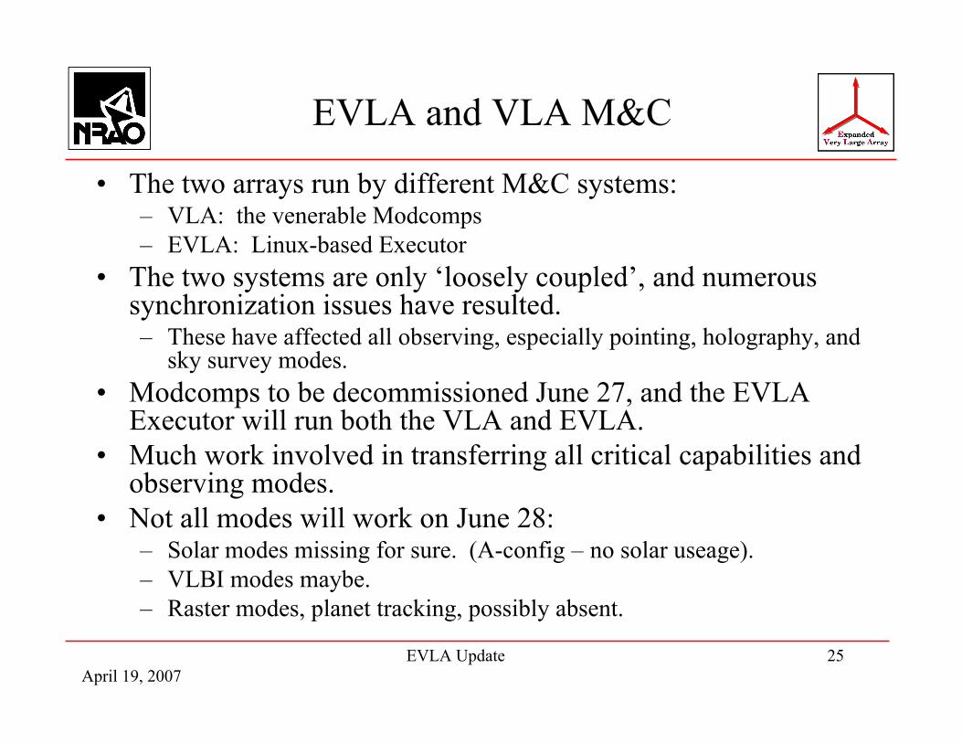
• The two arrays run by different M&C systems:– VLA: the venerable Modcomps– EVLA: Linux-based Executor
• The two systems are only ‘loosely coupled’, and numeroussynchronization issues have resulted.– These have affected all observing, especially pointing, holography, and
sky survey modes.• Modcomps to be decommissioned June 27, and the EVLA
Executor will run both the VLA and EVLA.• Much work involved in transferring all critical capabilities and
observing modes.• Not all modes will work on June 28:
– Solar modes missing for sure. (A-config – no solar useage).– VLBI modes maybe.– Raster modes, planet tracking, possibly absent.

April 19, 2007EVLA Update 26
Party!!!
• Want to come to a good party?• June 27, 2007 is *THE DAY* we turn off the
Modcomps for good.• An appropriate celebration (along with a well-
deserved plaque and citation) is being planned.
April 19, 2007EVLA Update 27
What works, and what doesn’t?
• Phase stability:– We believe ALL short-term EVLA phase stability issues are resolved.– Some peculiar problems still exist, are being tracked down.– RT phase now applied on most antennas – affects long-term phase
stability. Performance being checked.– Three modules show temperature sensitivity – now under study. No
quick resolution.– VLA now known to be responsible for phase jumps on VLA x EVLA
baselines, when frequencies change.– There is no fix for this. Calibrate when you change frequency.
• Amplitude stability:– Occasional drop-outs (1% of data, very brief (< 410 msec), very small
(~10% amplitude)) still occur.– One remaining large-scale, rare, phenomenon still being chased down.

April 19, 2007EVLA Update 28
Current issues, cont.
• Antenna pointing, etc.– Pointing fine, referenced pointing modes work (usually).– EVLA antennas often late on source – due to wrap condition not
known to Executor.
• Bandpass issues– EVLA bandpass does not have the ~180 degree ‘hook’ in the bottom 2
MHz of baseband that is on the VLA.– Continuum observations on VLA x EVLA baselines are significantly
degraded – a ‘closure’ error.– Can repair via baseline calibration (but SNR lost for good).– Can avoid via spectral line observations.– EVLA bandpass MUCH more stable than VLA – no standing wave.
April 19, 2007EVLA Update 29
VLA Bandpass AmplitudeDifferential Hourly Snapshots
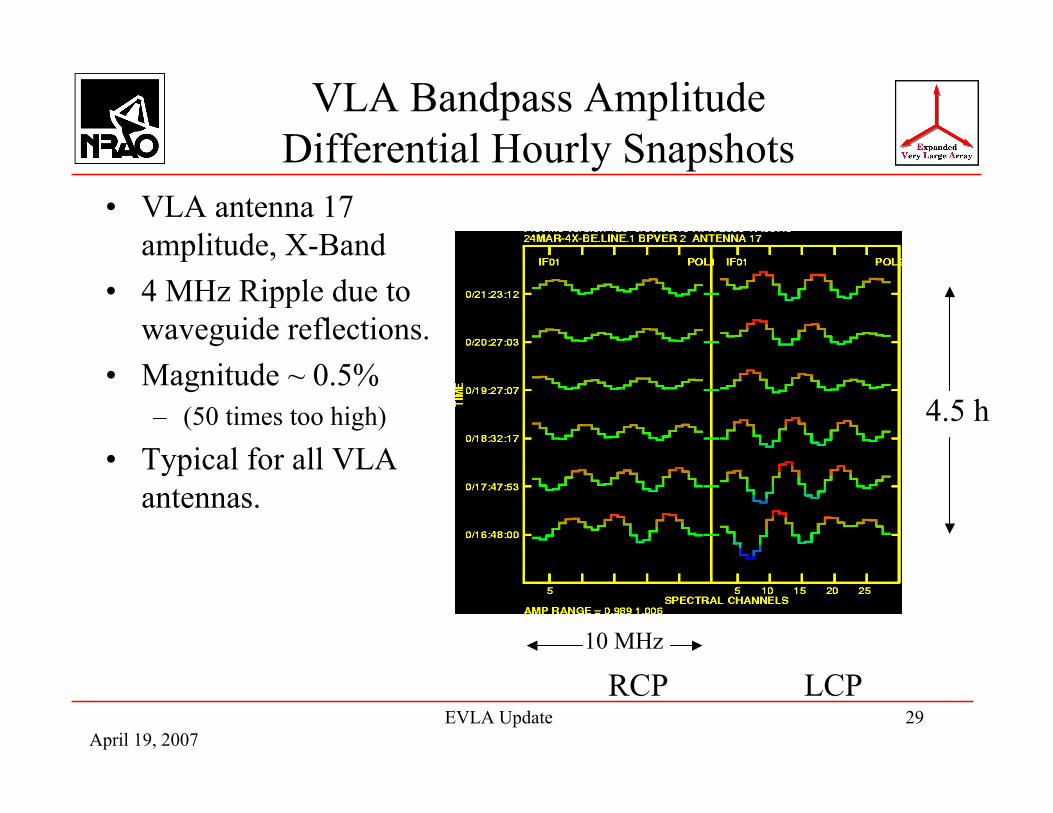
• VLA antenna 17amplitude, X-Band
• 4 MHz Ripple due towaveguide reflections.
• Magnitude ~ 0.5%– (50 times too high)
• Typical for all VLAantennas.
RCP LCP
4.5 h
10 MHz
April 19, 2007EVLA Update 30
EVLA Antenna 18 AmplitudeResults
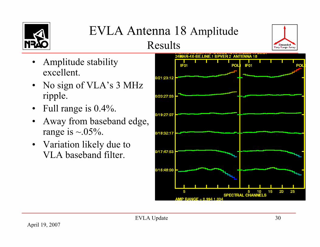
• Amplitude stabilityexcellent.
• No sign of VLA’s 3 MHzripple.
• Full range is 0.4%.• Away from baseband edge,
range is ~.05%.• Variation likely due to
VLA baseband filter.
April 19, 2007EVLA Update 31
Issues, cont.
• Doppler Tracking– algorithm between Modcomps and Executor not identical.– VLA x EVLA will not give sensible data with Doppler
tracking.– Must do spectral line with fixed frequency, and use off-line
processing to make doppler adjustments.– This problem will end after June 27, 2007!
April 19, 2007EVLA Update 32
Correlator
• Design and construction of correlator ‘sub-contracted’ toDRAO correlator group (Penticton, BC, Canada).
• All costs covered by Canadian NRC.• Their design is an extraordinarily flexible machine, with an
‘XF’ architecture• A 32 station correlator, but more than 32 antennas can be
input, with bandwidth reduction.• Recirculation provided for increased frequency resolution.• Vast number of ways to share resources internally, trading
inputs, or sub-correlators, or polarization, for more channels.• Full polarization, pulsar modes, phased array, VLBI-ready,
extensive subarraying, etc.
April 19, 2007EVLA Update 33
Software!
• We have major work ahead in software:– Correlator modes and operation.– Telescope scheduling, archiving, default image generation.– Calibration of 2:1 BWR data.– Imaging
• 2:1 BWR ratio imaging• Polarization (removal of beam polarization)• RFI excision• Multiple-direction self-calibration• Management of non-coplanar imaging• Management of spectral line cubes.
• The EVLA proposal underestimated software costs (if weknew then what we know now …)
• Remaining contingency will be reserved for hardware.• Assistance from NRAO headquarters will be needed to meet
the software requirements.
April 19, 2007EVLA Update 34
Major Future Milestones
• Modcomp control computers turned off June 27, 2007• Test prototype correlator on the sky Apr – Aug 2008
– Four antenna test and verification system– Not available for science
• Full Correlator Implementation Jun ’09 – May ‘10• VLA’s correlator turned off late 2009 ?
– New correlator capabilities will be much greater– About 6 VLA antennas will not be useable (temporarily)
• Last antenna retrofitted Sept. 2010• Last receiver installed Sept. 2013

April 19, 2007EVLA Update 35
Correlator – FIR Filter
• Each of 8 inputs, each 2.048 GHz wide, is digitally divided into16 sub-bands.
Input data stream:2 GHz wide:4096 Gsamp/sec x3 bits • Each output data stream is variable in width and frequency.
• Width can be 128, 64, 32, … ,03125 MHz.
• Frequency can be anywhere within 2 GHz input.
• Each output goes to a separate sub-correlator, providing 1024spectral channels.
16-port FIR filter
April 19, 2007EVLA Update 36
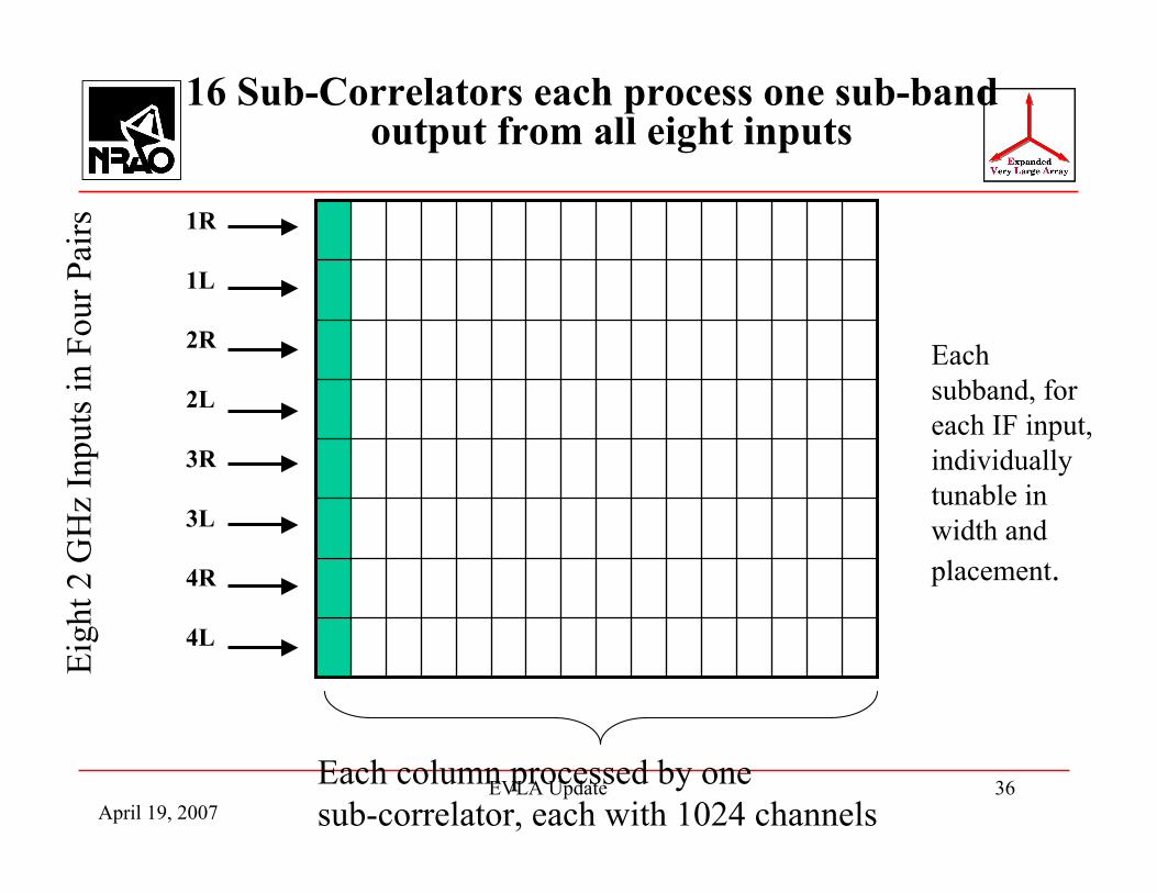
16 Sub-Correlators each process one sub-bandoutput from all eight inputs
Eigh
t 2 G
Hz
Inpu
ts in
Fou
r Pai
rs 1R
1L
2R
2L
3R
3L
4R
4L
Each column processed by one sub-correlator, each with 1024 channels
Eachsubband, foreach IF input,individuallytunable inwidth andplacement.

April 19, 2007EVLA Update 37
Correlator Flexibility
• Resources from any sub-correlator can be given to any othersub-correlator.– Doing so doubles the spectral resolution of the recipient sub-correlator– 15 sub-correlators can be given to one – improving spectral resolution
16-fold.
• Resources from any input IF channel can be given to any otherinput IF channel.– Increases resolution for one channel up to 16-fold.
• Both tradeoffs can be done simultaneously!– Increases resolution up to 256-fold.
• If this is still not enough resolution, recirculation is availableon four IFs, providing up to 4 million total channels/baseline.
April 19, 2007EVLA Update 38
Correlator Status
• Detailed design nearly complete.• Breconridge (the contract manufacturer) has delivered a fully
populated baseline board for detailed testing in Penticton.• Baseline board is large: 51 x 41 cm, 28 layers, 85000
connections, 95000 vias, 1.2 km trace length, 11802 parts.• Station board also populated and in testing in Penticton.• Phasing board design delayed. All other boards completed.• ASIC correlator chip passed (yesterday!) all 30 tests at full
speed! All FPGAs are ready, including the filter.• Prototype correlator (4 stations) expected for on-sky testing in
June 2008.