Embed Size (px)
Citation preview


Fig. 6,


The other facade (figure 10) &Q often gave rise to ccmeinuation, but never because a ccmtimation was regar&zd as static n~.;sq. This iIlustrates the kqm-tzmt point ‘that continuations may etipe:ciened althsugh nst requireA mere1.y to keep the body balm&.
The continuations experienced for ~E&S 10 and I.1 present interesting data relating to tie perception of form:
The continuation is experiencd to be more or 1~~s symmeti to thle ~d~~niinal figure comprising the :&de. This smxm+ to be conditioned by t&e qmienced symmetry and rqgk1.15~ of Ik~e facade itsellf.
Thus with reference to the aqect in figure 10, severa subjects consider that the cuntimatim would exat: tly resembk? the facade, were they to be placed diametrically opposite tt3eir present point of observakm.’ Some- &ting similar is true regarding the facade in figpre 11, tith certain ~MKL= ficaticms; it is at least generally :he case that the subject expezts the ctbrk
tinwtion to be “pointed” similarly to the facade. Tkn some instants, there is zi partkuh~ variant 0f this ge~er3.l way WE
experiencing the continuation: ~;hen observiq 4the body in figure 10, scxzx few subjects remark that the star-shaped continuation is rotated a little in relation to the facade, so that tw arms lclf the star end at the 6 points c-8 the facade furthest away from the observer, P[n the situation .i~, figure ‘11, there is a similar form of experience: the arms of the protruding star faming the continuation are consider& to end at the 6 rearmost points of the fa- cade, ~8 that behind each depession in the facade there is a raised part of the continuation, and vice v:rsa..
This type of continuation is termed a “reverse”, as in scame respects it is thre*dimensionally reverEed in relation trs t1he facade.
These two configurations 21re not least i&resting because their burbd- ary edges and the supportiq; plane petit Imare types of continuation structures than the aspects we have hitherto been con~zemed with. This ass~tion is based on the author’s ianalysis of .what has been cakd “signs &Emit&g tie type of continu:aeish”.
Figure IO a shows the aswet from figure 10 viewed slightly from above and TV the left. It is amon@ c&r qthings possible to experience this facade as continued eit’er as d plants, each emanating from neighbouring bound- ary edges, s~h as A and B, or as 6 planes each issuing from neighbouriag
undary edgs @f the type C and D. One pp!.ane from each of these tws continuations &IS bee12 indicakd in the draw&. M the first case,, the coMinuation wti -verge, for example to a point; in the latter case, it WOE tend to fom a 6-planed prism in which aU the opposite pkmes zm yaraM, with pknty of possibk ektiures differing from the facade. A third
csntinuatiun of the supporting plane urkx tial hindranCx2 to any of the Cltn-
it does Inegate some: sim at pssi bitit& i
Contkued experiments will be necessarv to provide futiher iti,ocr- rn;~tbn regarding this tqk On the basis of &e data to hand at preslxit, WC: may abw ourselves to fcxrnulate the matter as foUows: apparei.it1.y th4:re are configurations such that their experienced continlWions ai7z particularly influenced bl~ the facade’s voluminal figure, and other facacks where the experienced ccmtinuation is sometimes most influenlxd by p~rt:s uf
irl in
the bounder polygon, sometimes by the flaca\de’s voluminal figure. TO summarise: two plane configurations h.ave been mentkned wlkriclh
some cases gave rise to the experieasce cb t.he.re being a 4: ontinuati.on, others of n0 cootinuati0a. An the cases where a conkuatb~ was p:Ws-
tu this malysi(;, Carrie auk cm the basis of the auth0f~ CB xi3
was to be expxted that dI xl=lese wwii0U~ rear structuIi:es 4umrh-d in dub 6% Ra~:r=-*fi~ *-I WWUL~U 4M ww lE.-xpLrluaa Cal l.LlcLt~lldP.
~‘.4~&.z*P Tf& however, is jloe
What occurs at all. When presented with the: asp3~t shown in figure 33, the subjSs report both the continuation rest-:mbling the facade in one or ancbther manner, and that comprising a ps tion-i. e. 3~2 A43 varbtion mentioned with reference ts figure 10 a. regard to k latter ccmtinuation, the slant 0f the continuing planes signdlled by the p’: irs of bundary edges of the A13 type pk3ys a part in the y”nenomenologg LL thr: situation.
On the other hand, the 21 subjects whs were confronte with the aspect in figure 10, togetker with 10 other subjaxt5, all. stated that if there wa,s any continuation in figure $1, it resemble e facade, although m~A!i- fied k some way.
enle phenornenckqgically, we found (I) that the rear part of the body ‘iNas considered to br= symrnetrkal ,to the facade, (2) that the continuation ‘ivas thr:: three-dimensional “reverse” of the facade. (3) Althougl~ this facades b;f

a

T El

77- w
d” P&J. - Ii. The area of the supporting plane relative to a configurati~l~ hii5 alSO been
varied (cf. fig. 5). This matter must be omitted here.

18
re 4 by the g0sit.h t, ix e subjects e colrLirtuation consists of ibur tria pkmes, e,ach 0
edge represente~d in the bourdar~ pdygor~. it$ regard to tie aspect in figure 8, kmwWef, the cmtinu d to ir~Wle b0th planes with edges represe:
pob!gon, and planes of which nothing was iandude~ L as an example the srkbjects wlm lsonsirllered that %43re six tive-
sided planes in the cOn u~Sion, Oi which me W;LS, in the facade, it is appmm~ *that irn tk case, the a sin$e comer od.y vaguely chai:zcferises kw the subj 2s experienced
wtinuationa. It would 35 ne:s,essary to know 1.e locations cr? e continuation’s mrners if iime v2.s to deduce tiie ex
e table (p. 23) g?ves the results for indkatiows of e ddance, as we11 as the lateral position. In addition, the differmce between the points furthes
other has been mted. For each of the thr?:e aspects, t ’03s first indicated the distame three times, ad th:n the lateral
sition three times. The figures nioted in. the table are tke firnal resuks f several readjustments. They wt:re instm:ted to icdicat~ the distance
tE_re pinter marked a hp3thetit:d plane passirag throqh the ,
oslt coniaer of the continuatim and pr-allel I0 the fro .at edge 0l the srting plane, The lateral posi~iora wa; fo be shown by marking the
irectiun d the comer ccmcemed LIP.. right-m_Slcs to e fr~s;,t edge of the ~sssppor5lkg Tlane. AI1 these measurement5 were made after the subjects
their de* ‘2 ions of the ccmtimmion; birm4dns visio was used, mr3 the subjects possffised rmnXIl sight.
4se later31 indications were msried 0ut by the sutujed turning Beft-LE?zd wheel just under the front 43f thi: table’at which hc sat (cf. figure 9). Th.e distance was marked by movin!,y, the verticd bw fOrwards Or
15. Ih situaticm 2, the latt. tral 0inter mrrve 1 I cm behin tCqrm.sst pokt of the facade, the c istarmA7ar mtsving 8 c9 1. to tSIc right sf the fimde’s outermost @&-hard pcsi~C he cosrespordng figures figUD2 4 are 15.5 Cm. and 9.5 Cm; fil,g fig.iE 3, 10.5 atl he snb jects
e rders during tJte :xpenirmmts. They res%d their c 4~) 50 cm, from the

Fig. 12.
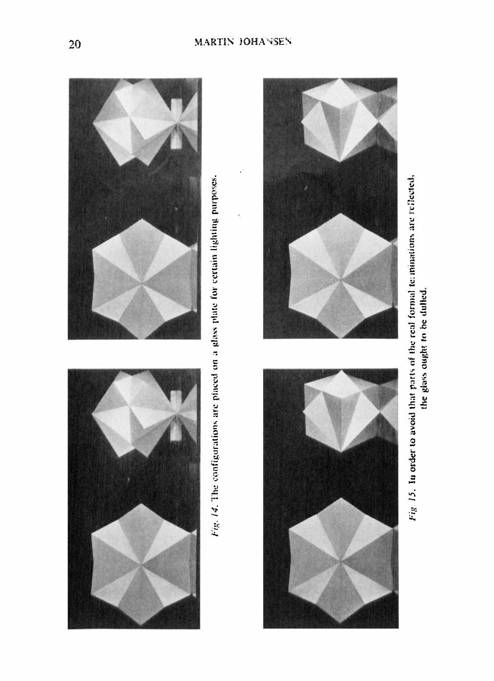


Fig. 24~. The diagrm are plaltiy dram from the ieft- hand ster~~~photog.rapI 1s in figures 2, 84 rmd 8. All tic observer8 list4 in th0 tablls thought the rmm most point lay on the sug~- porting @ane, with the ex- ception of v, d. O.!, ‘CK~KI con- side,r that it 1,ay ~0rn~+ what alMNe.
most point of the actual termination. z* R. M., 1. w. !I., M. ES. 8. and F. W. I-L were of the opinion that the ~oinb was above, the remaining sub- jects that it was on, the supporting $&tie. It is not clear whether J. W, J. and
. H. assumed some form of support apart from thevisible ~upportiog phu~e, although they were infor.:~- cd that there was no such additional support.
Fi&‘. 8C, By the F4’XUT31Cai
point of the actuali termPna- tism is bczre understood the uppetm~ost of the pecked c4Nners. AU sub,jects presumed that the point lay above the sup- porting plane. The rcsk&s for the indications of height have not bte~ included in the table.

Y. d. a
M.H.B.
6.J.
E. .8.
E. E. PA.
FJKH.
F.J
- I.1 - 7.6 _ 3.6 --:O,& --2 .2 - 0.4
- 2.6 3.Q - 7.3 2.0 - 8.8 4.6 - 9.7 4.5 - 4.4 2.6 - 0.9 2.6
- 1.7 - 9.3 - 8.2 - 6.1 - 4.8 -I- I.7
- 2.1 - 8.3 - 5.7@ ---la5 - 1.2 + 1.9
- 1.7 1.5 - 7.2 3.4 - 1.7 4.0 --PO.1 3.4 - 1 .o 0.3 0.0 2.9
- 0.6 - 4.9 - 4.3 - 9.2 - 1.3 - 1.0
+- 27 - 6.1 _q 1.3 -#-= 8.2 + 0.9 -I- 1.9
-+ 1.1 1.6 - 7.1 I.0 - 2.2 1.1 + 0.1 0.6 -+ 1.7 1.1 -f- P.6 0.5
=I= 1.5 - 6.8 - 2.4 - 0.4 -b_ (PA -j- 1.4
+ 0.1 - at? + 3.1 ---a.3 - 1.04 += 3.9
- 0.2 0.8 - 4.0 a7 + 3.3 0.6 --a*7 1.0 - 4.4 3.4 ?I- 2.0 2-2
- 0.7 - 1.J + 3.7 --a.3 - 2.0 + I.7
-I- 1.0 -==10*4 - 4.2 --10.4 -t- LB + 5.8
+ a4 4.2 - 8.3 2.4 - 4.5 2.3 --IO.8 1.1 - 0.6 1.’ J- 5.1 1.7
- 3.2 - 9.0 - 2.2 -=--I 1,s 0.0 -I- 4.J
- 1.0 - 4.3 *- 5.3 - 3.1 ‘- 2.2 - I.0
+ 0.5 1.8 - 2.2 2.1 .- 5.7 1.2 - 2.1 1.7 - 2.1 0.7 -- 1.5 I.1
- I.3 - 3.8 - 4.5 - 3.R - 1.5 -- 2.1
I. 1I.R. M. assumed 5 3. J. W.J. as:;umd 8, continuing planes. 4, EL. M. 5, and the
2. h&H. B. 6, and the remaining subjects rest 4 such plams. 6 ctlntinuing planes.

An attempt ham been made to elucidate what indkates to an observer that an aspect e$I of swm-d plants is cuntinued i~ a particular way.
Tk@ study of such matters is fundamental for the extension of our knowledge con- wrning not only our gerceptim of polyhedral forms, but also our spatial exgerie a~ visual spwe is, amongst other things, structured by the objecti in it.
FronI Observations made by 3 number of subjects pmsessing normal binocular vision, it appears that both the facade and the surrounding spatial field ‘are con- ti muatian indicators in a ghenomenologi~cal sense.
Tha boundary edges of an aspect can iadicate from which of them the continuation a~ay emamatc, and in certain cases also the slant of the continuation’s planes.
Addition4 indicators are the facade’s voluminal figure taken as a whole, and the type of the form-relationship expericncsd between the iacade planes, which may be qpite another than the geometric reIatio3ship.
Furthermore, a foreign plane supporting t? )e facade may indicate the shape of