Embed Size (px)
Citation preview

THE FEATURES ON ASDA-A2

The Contents
Easy Settings for Cap. Relative AxisThis method can use to set Cap. Relative Axis without consume the COMPARE resource. Easy way to set up this Cap. Relative Axis than before.
Phase AlignmentThis function is used to align the E-Cam phase according to the a physical digital input signal.

An Application ExampleA Population ApplicationWhen the material feeding roller is a slave axis in a cutting machine which is requested to cut at the mark place for every cycle .
Slave Axis
Main Axis
DI7
DI_ALGN:0x35
1
2
1
2Capture Relative AxisPhase Alignment Function

New Way to Set Cap. REL Axis (1)Parameters Supported by version V1.038 Sub.19 (included).Please also reference to the training slides.P1-19 Capture/ Compare Extension Function.P1-20 Masking length.

New Way to Set Cap. REL Axis (2)The Mark Tracking Function ASDA-A2 is integrated a feature which will adjust its cutting length according to the difference from comparing the pulse number received to the standard one .

New Way to Set Cap. REL Axis (3)Alternative Settings for Syn. Capture Axis The new method no using macro instruction to set Synchronous Capture Axis is supported by firmware version 1.038 sub 19 and the version after this one.

New Way to Set Cap. REL Axis (4)The New Parameters The P1-19.X=1 is for repeating Capture Function operation and P1-20 is using to set masking distance.

New Way to Set Cap. REL Axis (5)The Operating Procedure

New Way to Set Cap. REL Axis (6)The PR Sample for new parameters

The Phase Alignment Function (1)How it works? When the a physical digital signal comes into the servo drive, the servo will align its phase to the signal.

The Phase Alignment Function (2)Where to install the sensor? The alignment sensor could be installed in different places according to different applications.
Machine position alignment.

The Phase Alignment Function (3)Where to install the sensor? Adjust material sending mechanism or adjust cutter to fit the mark.

The Phase Alignment Function (4)Where to install the sensor? Adjust the printing rollers to fit the mark.

The Phase Alignment Function (5)The Parameters P2-73 is used to set the conditions for E-Cam phase alignment.
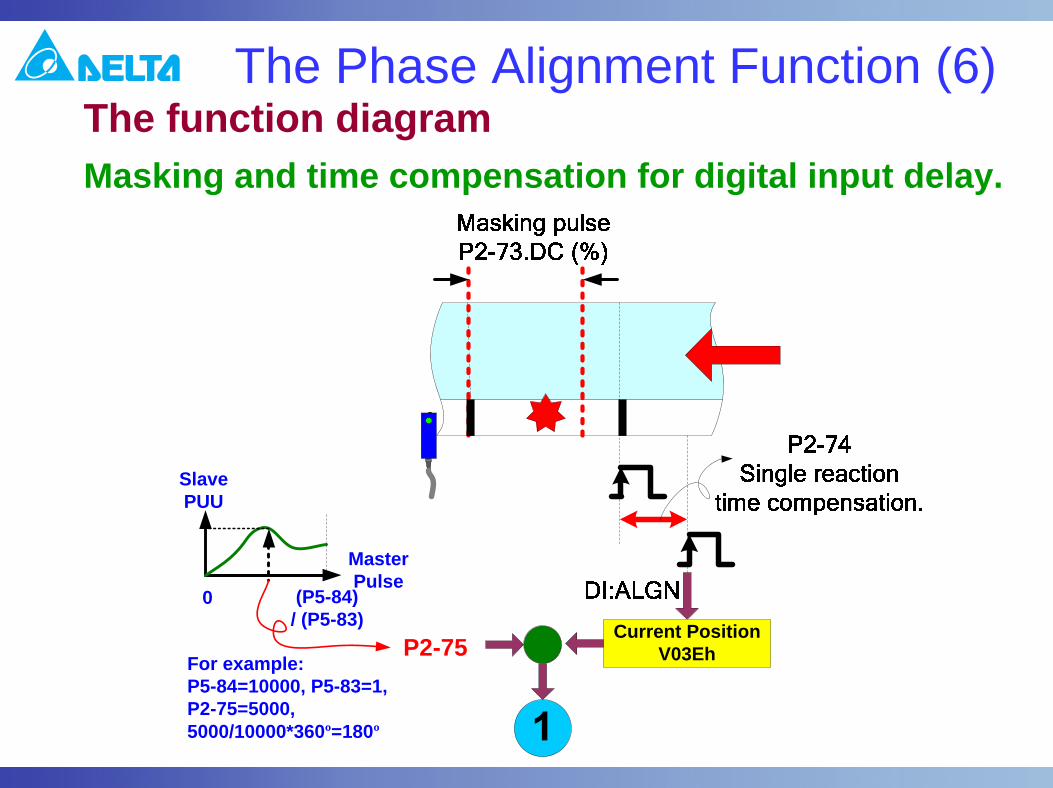
The Phase Alignment Function (6)The function diagram Masking and time compensation for digital input delay.
Current PositionV03EhP2-75
MasterPulse
(P5-84)/ (P5-83)
0
SlavePUU
For example:P5-84=10000, P5-83=1, P2-75=5000, 5000/10000*360º=180º

The Phase Alignment Function (7)The function diagram Define the filter function for averaging the error to avoid noise.
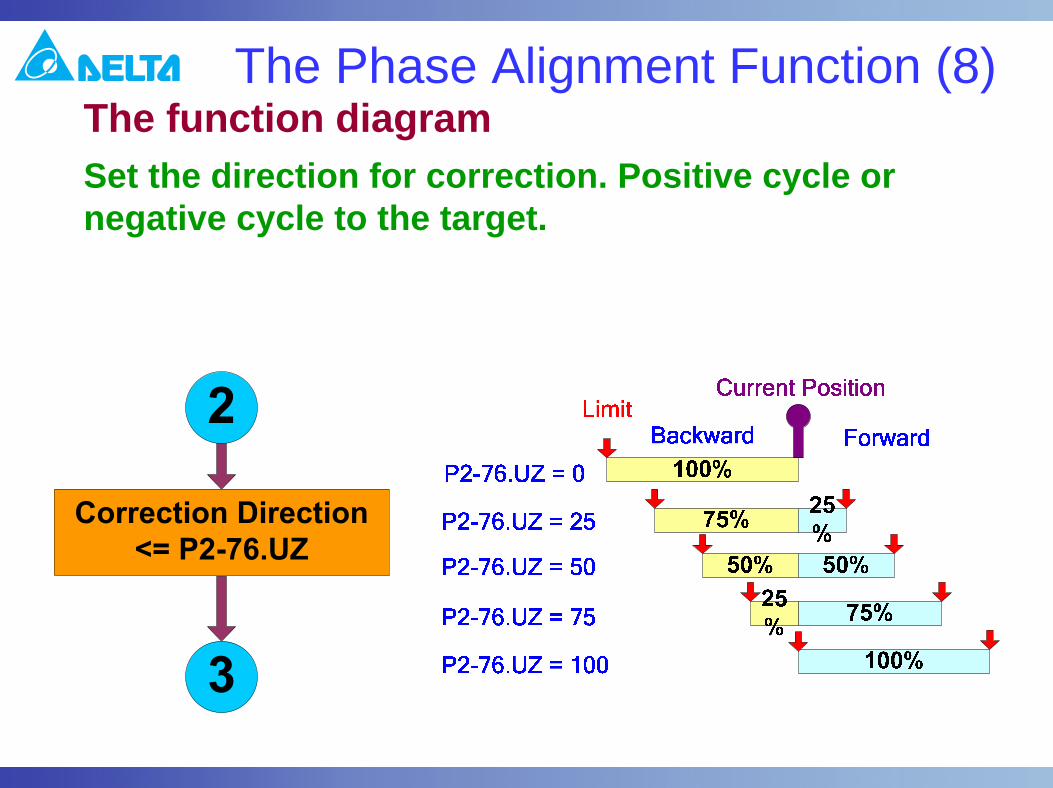
The Phase Alignment Function (8)The function diagram Set the direction for correction. Positive cycle or negative cycle to the target.

The Phase Alignment Function (9)The function diagram Set correction rate for adjustment within every cycle.

The Phase Alignment Function (10)The function diagram Enable the function and set the PR assigned by P2-73.BA properly (Type 2, INS, OVLP, Incremental, speed) . Reference next page.
Correction PUU in PR
P2-73.BA
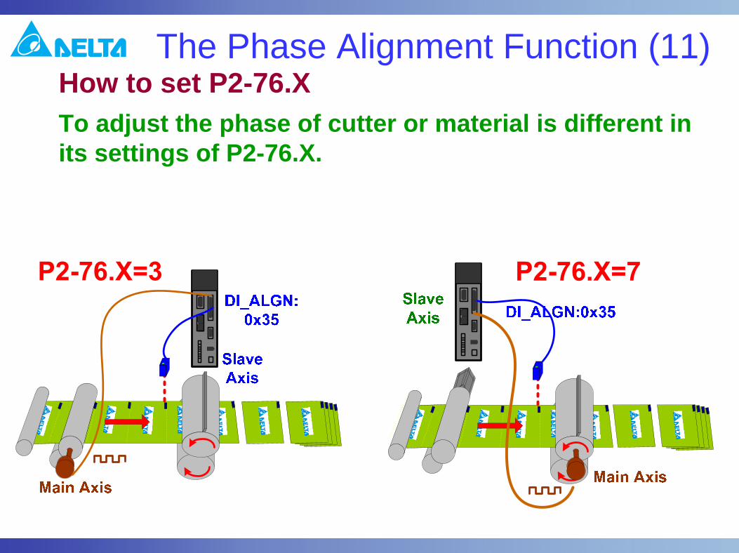
The Phase Alignment Function (11)How to set P2-76.X To adjust the phase of cutter or material is different in its settings of P2-76.X.

Master Pulse Command (1)Virtual master pulse generator In order to adjust the relative positions of current motor position and the position on E-Cam curve, the new feature can take out physical pulses from master or add pulses into E-Cam system.

Master Pulse Command (2)P2-77.X pulse modulationThis is for adding /subtracting pulses to the system.

Mask Master Command (3)P2-77.Y pulse to P5-87The adding pulses will be recorded into P5-87 by writing P2-77.Y.

Mask Master Command (4)Example (1)Adjust phase of cutter and record the number of pulses for delaying E-Cam engaging.

Mask Master Command (5)Example (2)Adjust the cutter by inverse virtual signal.
P2-77 = 0x040B. Have a - 4KHz virtual signal into E-Cam system and accept physical master signal simultaneously.
Slave PUU
MasterPulse
P2-77 = 0x0000. Shut down the virtual signal generator.
P2-77 = 0x0030. Write ( virtual pulse # + (P5-84/P5-83)) to P5-87 for offset purpose.
Physical signal
Virtual signal

Thank You
7/1, 2011