Embed Size (px)
Citation preview

1
[email protected] May 2005
THE FIRST-ORDER DELTA-SIGMA
MODULATOR
Gábor C. Temes
Richard Schreier
José Silva
[email protected] May 2005
Outline
• Quantizers and quantization noise
• Binary quantization
• MOD1 as an ADC
• MOD1 as a DAC
• MOD1 linear model
• Simulation of MOD1
• MOD1 under DC excitation
• The effects of finite op-amp gain
• Decimation filters for MOD1

2
[email protected] May 2005
Quantizers and Quantization Noise (1)
• Unipolar N-bit quantizer:
[email protected] May 2005
Quantizers and Quantization Noise (2)
• M-step mid-rise quantizer:
• M-step mid-tread quantizer:

3
[email protected] May 2005
Quantizers and Quantization Noise (3)
• Sampled signal:
• Quantization error:
16-step
quantization
used
f/fsirrational!
[email protected] May 2005
Quantizers and Quantization Noise (4)
• FFT:
• Sampled signal (f = fs/8):

4
[email protected] May 2005
Binary Quantization (1)
• Quantization error:
• FFT:
3ff
[email protected] May 2005
Binary Quantization (2)
• Modeling the gain:
• Minimize mean square error of e:
opt.:
∑=
∞→=
N
n
NN
e ne0
212 )(limσ

5
[email protected] May 2005
MOD1 as an ADC (1)
• Linear modeling:
[email protected] May 2005
MOD1 as an ADC (2)
• Continuous-time implementation:
• Discrete-time switched-capacitor implementation:
y

6
[email protected] May 2005
MOD1 as an ADC (3)
• Continuous-time waveforms:
• Z-domain model: change in
v pattern
v
y
v
y
[email protected] May 2005
MOD1 as an ADC (4)
• Stable operation:
∑−
=∞→
==1
0
1 )(limN
n
NN
vnuu !
If y(n) is bounded,
Perfectly accurate for N → ∞.

7
[email protected] May 2005
MOD1 as a DAC
• Error feedback structure: → recycled error!
= y - v
Same as for ∆Σ loop → another option for DAC. (For ADC, impractical!)
[email protected] May 2005
MOD1 Linear Model (1)
• Z-domain analysis:

8
[email protected] May 2005
MOD1 Linear Model (2)
• Frequency-domain analysis:
2
32
2
2
π2
)(9
0
OSRMSQNR
q
u ==σ
σ
Mean square of qo:
(inband shapedquant. noise)
Signal-to-quantization
noise ratio
(for OSR >> 1)
# of levels in Q
[email protected] May 2005
Simulation of MOD1 (1)
• Output spectrum for full-scale sine-wave input:
Looks ok, but SQNR 5 dB less than the formulaic.

9
[email protected] May 2005
Simulation of MOD1 (2)
• SQNRs for different frequencies:
Sine wave inputs
[email protected] May 2005
Simulation of MOD1 (3)
• In-band quantization noise power:
Vref = ±1
mean square of
inband noise
DC input level
DC input level

10
[email protected] May 2005
MOD1 Under DC Excitation (1)
• Idle tones:
• u = y(0) = ½:
• For u = 0.01, tones at k.fs/200!
possible values of s(n)
k = 1, 2, …
[email protected] May 2005
MOD1 Under DC Excitation (2)
• Let u = a/b, a and b odd integers, and 0 < a < b. Also, let |y(0)| < 1.
Then, the output has a period b samples. In each period, v(n) will
contain (b+a)/2 samples of +1, and (b-a)/2 samples of -1.
• If a or b is even, the period is 2b, with (a+b) +1s and (b-a) -1s.
• If v(n) has a period p, with n +1s and p-m -1s, the average
v = (2m - p)/p. Hence, u = v is also rational. Thus, rational
dc u ⇔ periodic v(n).
• Periodic v(n): pattern noise, idle tone, limit cycle. Not instability!
• For u = 1/100, tones at k·fs/200, k = 1, 2, … some may be in the
baseband. Often intolerable!
11
[email protected] May 2005
Stability of MOD1
• MOD1 always stable as long as |u| ≤ 1, and |y(0)| ≤ 2:
• If u > 1 (or u < 1), v will always be +1 (or -1) ⇒ y will increase (or decrease) indefinitely.
• If |u(n)| ≤ 1 but |y(0)| > 2, then |y(n)| will decrease to < 2. Output spectrum always a line spectrum for MOD1 with
dc input (rational or not).
( )[ ] )()1(sgn)1()( nunynyny +−−−=
|[ ]| ≤ 1 ≤ 1
≤ 2
[email protected] May 2005
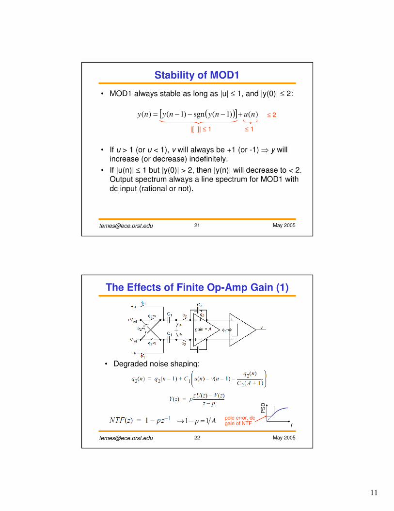
The Effects of Finite Op-Amp Gain (1)
• Degraded noise shaping:
Ap 11 =−→pole error, dc gain of NTF f
PS
D

12
[email protected] May 2005
The Effects of Finite Op-Amp Gain (2)
• Dead zones:
for u > 0, eventually ku > 1
and two 1’s occur.
v = -1
+1
-1
v = -1
+1
-1
For A < ∞: , p = 1 - 1/A
Ideally:
[email protected] May 2005
The Effects of Finite Op-Amp Gain (3)
• For v > 0,
(Two 1’s occuring)
For A ≈ 103:
umin ~ 1/(2A)

13
[email protected] May 2005
Decimation Filters for MOD1 (1)
111
11)(
−
−
−
−=
z
z
NzH
N
f
ff
π
π )sin()(sinc =
Averaging
over N samples
(running-average)
MOD1 H1(z)u v
OSR
• The sinc filter:
[email protected] May 2005
Decimation Filters for MOD1 (2)
• Responses:
h1(n)
Gain response
H1(z)
n
1/N
Areas aroundnotches fold back
to baseband after decimation if N = OSR.

14
[email protected] May 2005
Decimation Filters for MOD1 (3)
• Implementation:
Total noise after ideal LPF; Much less than σq12!
Inband noise after H1: Inband noise before H1:
Total noise after H1; Too much!
Assuming e(n) and e(n - N) are uncorrelated:
σe2
[email protected] May 2005
Decimation Filters for MOD1 (4)
• The sinc2 filter:2
12)1(
)1()(
−
−=
−
−
zN
zzH
N

15
[email protected] May 2005
Decimation Filters for MOD1 (5)
• Response:
• Implementation:
[email protected] May 2005
References
1. D. A. Johns and K. Martin, Analog Integrated Circuit Design, John Wiley & Sons, New York,
New York, 1997, pp. 450-451.
2. J. C. Candy and O. J. Benjamin, “The structure of quantization noise from sigma-delta
modulation,” IEEE Transactions on Communications, vol. 29, no. 9, pp. 1316-1323,
September 1981.
3. V. Friedman, “The structure of the limit cycles in sigma delta modulation,” IEEE Transactions
on Communications, vol. 36, no. 8, pp. 972-979, August 1988.
4. O. Feely and L. O. Chua, “The effect of integrator leak in - modulation,” IEEE Transactions
on Circuits and Systems, vol. 38, no. 11, pp. 1293-1305, November 1991.
5. R. M. Gray, “Spectral analysis of quantization noise in a single-loop sigma-delta modulator
with dc input,” IEEE Transactions on Communications, vol. 37, no. 6, pp. 588-599, June
1989.
6. M. O. J. Hawksford, “Chaos, oversampling, and noise-shaping in digital-to-analog
conversion,” Journal of the Audio Engineering Society, vol. 37, no. 12, December 1989.
7. O. Feely and L. O. Chua, “Nonlinear dynamics of a class of analog-to-digital converters,”
International Journal of Bifurcation and Chaos, vol. 2, no. 2, June 1992, pp. 325-340.
8. R. Schreier, “On the use of chaos to reduce idle-channel tones in delta-sigma modulators,”
IEEE Transactions on Circuits and Systems I, vol. 41, no. 8, pp. 539-547, August 1994.
9. J. C. Candy, “Decimation for sigma-delta modulation,” IEEE Transactions on
Communications, vol. 34, no. 1, pp. 72-76, January 1986.