Embed Size (px)
Citation preview
FDS®
The Flow-Drill Screw for
High-Strength Sheet
Joints

ImprintEditor:
EJOT GmbH & Co. KG
Industrial Fasteners Division
57319 Bad Berleburg
Germany
Print:
© by EJOT GmbH & Co. KG
EJOT®, FDS®, ALtracs® and EJOMAT® are registered
trademarks of EJOT GmbH & Co. KG.
TORX®, TORX PLUS® and AUTOSERT® are registered
trademarks of Acument Intellectual Properties LLC.
All technical data may be subject to technical
improvements.
3 TheProduct
5 TheFDS®
6 Designs
10 DesignRecommendations
12 InstallationInstruction
14 StaticStrengthProperties
15 PerformanceCharacteristics
16 JoiningwithoutPilotandClearenceHole
Content
®
3
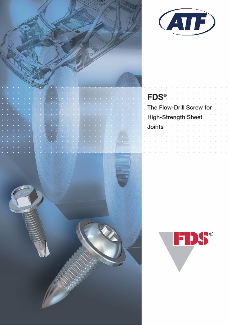
Convincing facts about the FDS® joint
l removableandhigh-strengthscrewjoint,withoutpart preparationslikepunchingordrilling
l noproblemsregardingholeoverlappingofclearanceandpilothole
l nomaterialwastewhileformingthethroughdraught/nochipsduringthreadforming
l severalmetricthreadsareengaged
l highsafetymarginduetolargedistancebetweeninstalla-tionandstrippingtorque(highassemblyreliability)
l highshearingstrengthandpull-outforce
l assemblyindifferentsheetsurfacesispossible
l highbreakloosetorqueandvibrationresistance
l repeatassembliespossiblewithstandardmachinescrews
l earthingassemblies(accordingtoDINVDE0700)arepractical
l easytodisassembleandrecyclable
l lowoveralljointcosts
The Product
4
® Secure screw joints for steel and aluminium sheetsDuetoitsgoodprocessingandperformancecharacteri-stics,steelisstillthemostimportantmaterialinthesheetmetalprocessingindustrybutthecompetitionfromlightermaterials,suchasaluminium,isincreasing.Forthisreasonthesteelindustrydevelopedanumberofnewsheetmateri-alsoverthelastfewyearswhichfeaturehighstrengthsandatthesametimegoodformingcharacteristics.Inadditiontothetypicaldeep-drawn,mild,unalloyedsteelsforcoldfor-ming(acc.toDINEN10130)themicro-alloyedthinsheetswithhigheryieldstrengthH240M(ZStE260)–H400M(ZStE420)accordingtoDINEN10268(SEW093)andthedualphasesteeltypeDPaccordingtoSEW097,part2,shouldbementioned,sincebothmaterialsplayasignificantroleinthefieldofhighstrengthsheetassemblies.
ForforgeablealuminiumalloyintheautomotiveindustrymainlythermalhardenableAlMgSialloysfromthe6000groupinthestrengthgradeT4uptoT6areusedinadditiontothenon-hardenablealloysofthe500group.TheT4/T5gradesarepreferredforsheetmaterialandT6fortheextru-sionprofiles.Themaximumutilisationoftherespectivesteelandaluminiumpropertiesoftenrequiresareconsiderationofthecommonlyusedassemblymethodsinparticularwhenjoiningdifferentmaterials.
TheflowdrillingFDS®Screwenablesahigher-strengthjointduetolargerthreadengagementintheformeddrau-ght.
Thefemalemetricthread,formedwithoutproducingchipsduringfastening,istruetogaugeandforthatreasonacommonmetricscrewcanbeusedincaseofrepairs.
Duetothetightfittingengagementofseveralthreadsthescrewjointiswaterproofandgas-tightanditcantransferhighpull-outandshearforces.Theheatdevelopmentduri-ngflow-drillingisharmless,becauseitisbelowtherecry-stallisationtemperatureoftheassemblymaterialsandiscountedtowardsthelowtemperaturejoiningmethods.Thelowremainingtemperatureissufficienttoshrinktheformeddraughtontothescrewafterassemblywhichguaranteesahighdynamicsafety.
Forthisreasonadditionalsafetyelements,suchasadhe-sivecoatings,canbeeliminated.
Sincecomponentpreparations,suchaspre-drillingorpunchingarenotnecessary,knowntoleranceproblemsandliningupofclearanceholesareathingofthepast.Theone-sidedaccessibilityofthecomponentenablesassem-blyintohollowprofilesorextrusionssimilartootherjoiningmethods.
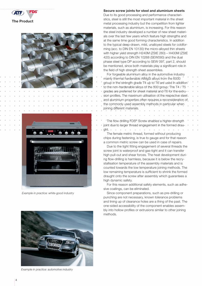
Example in practice: automotive industry
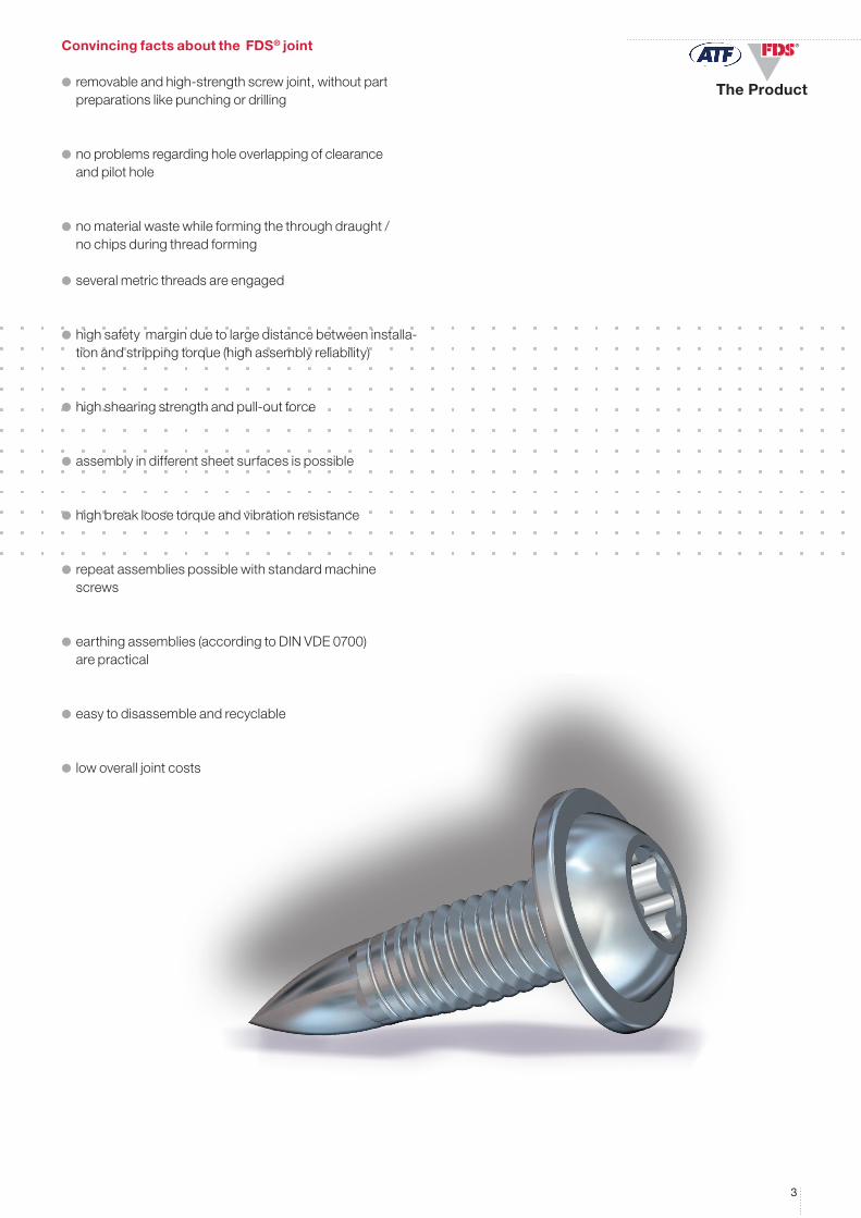
Example in practice: white-good industry
The Product
55
1. 2. 3.
4. 5. 6.
1. 2.
3. 4.
5. 6.
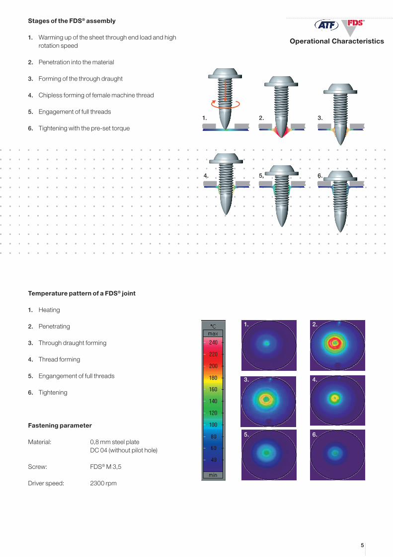
®Stages of the FDS® assembly
1. Warmingupofthesheetthroughendloadandhigh rotationspeed
2. Penetrationintothematerial
3. Formingofthethroughdraught
4. Chiplessformingoffemalemachinethread
5. Engagementoffullthreads
6. Tighteningwiththepre-settorque
Temperature pattern of a FDS® joint
1. Heating
2. Penetrating
3. Throughdraughtforming
4. Threadforming
5. Engangementoffullthreads
6. Tightening
Fastening parameter
Material: 0,8mmsteelplate DC04(withoutpilothole)
Screw: FDS®M3,5
Driverspeed: 2300rpm
Operational Characteristics
6
®
Fz [N]
Duetothenumerouspossiblesheetmetalapplications,severalstylesoftheFDS®Screwhavebeendeveloped.
TheStandardtypeispreferredforautomatedassemblywithoutpilothole.
Forassemblywithhand-heldfasteningequipmentapilotholeincombinationwiththePKSTypeisuseful.
FormanualassemblywithoutpilotholetheFDS®TypeBSisrecommended.Inthiscasepleaseconsiderthechip-pingthatoccursduringdrilling.
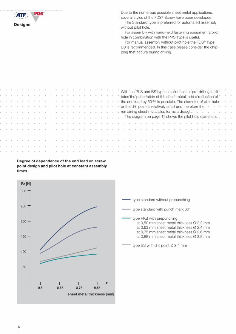
WiththePKSandBStypes,apilotholeorpre-drillingfacili-tatesthepenetrationofthesheetmetal,andareductionoftheendloadby50%ispossible.Thediameterofpilotholeorthedrillpointisrelativelysmallandthereforetheremainingsheetmetalalsoformsadraught.
Thediagramonpage11showsthepilotholediameters.
Degree of dependence of the end load on screw point design and pilot hole at constant assembly times.
type standard without prepunching
type standard with punch mark 60°
type BS with drill point Ø 2,4 mm
type PKS with prepunchingat 0,50 mm sheet metal thickness Ø 2,2 mmat 0,63 mm sheet metal thickness Ø 2,4 mmat 0,75 mm sheet metal thickness Ø 2,6 mmat 0,88 mm sheet metal thickness Ø 2,8 mm
sheet metal thickness [mm]
Designs
77
®
®
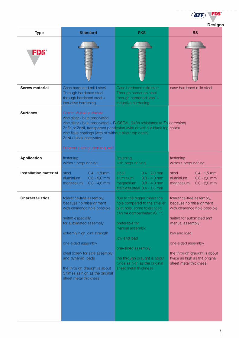
Type Standard PKS BS
Screw material CasehardenedmildsteelThroughhardenedsteelthroughhardenedsteel+inductivehardening
CasehardenedmildsteelThroughhardenedsteelthroughhardenedsteel+inductivehardening
casehardenedmildsteel
Surfaces ChromVIfreesurfaces:zincclear/bluepassivatedzincclear/bluepassivated+EJOSEAL(240hresistancetoZn-corrosion)ZnFeorZnNi,transparentpassivated(withorwithoutblacktopcoats)zincflakecoatings(withorwithoutblacktopcoats)ZnNi/blackpassivated
Differentplatinguponrequest!
Application fasteningwithoutprepunching
fasteningwithprepunching
fasteningwithoutprepunching
Installation material steel 0,41,8mmaluminium 0,85,0mmmagnesium 0,8-4,0mm
steel 0,42,0mmaluminium 0,84,0mmmagnesium 0,8-4,0mmstainlesssteel0,41,5mm
steel 0,41,5mmaluminium 0,82,0mmmagnesium 0,8-2,0mm
Characteristics tolerance-freeassembly,becausenomisalignmentwithclearenceholepossible
suitedespeciallyforautomatedassembly
extremlyhighjointstrength
one-sidedassembly
idealscrewforsafeassemblyanddynamicloads
thethroughdraughtisabout3timesashighastheoriginalsheetmetalthickness
duetothebiggerclearanceholecomparedtothesmallerpilothole,sometolerancescanbecompensated(S.11)
preferableformanualassembly
lowendload
one-sidedassembly
thethroughdraughtisabouttwiceashighastheoriginalsheetmetalthickness
tolerance-freeassembly,becausenomisalignmentwithclearenceholepossible
suitedforautomatedandmanualassembly
lowendload
one-sidedassembly
thethroughdraughtisabouttwiceashighastheoriginalsheetmetalthickness
Designs

8
®
WN 2147
®
WN 2141 WN 2142 WN 2143WN 2141 WN 2142 WN 2143 WN 2147 WN 2151 WN 2152 WN 2153
b b b b b b b
lglglglglglglg
L
S K K
D
L
max. 5° 90°
D
c
L
D
S KL
S K
D
L
D
KL
90°
c
f
D
L
d1d1d1d1d1d1d1
D
R R
WN 2141 WN 2142 WN 2143 WN 2147 WN 2151 WN 2152 WN 2153
b b b b b b b
lglglglglglglg
L
S K K
D
L
max. 5° 90°
D
c
L
D
S KL
S K
D
L
D
KL
90°
c
f
D
L
d1d1d1d1d1d1d1
D
R R
WN 2141 WN 2142 WN 2143 WN 2147 WN 2151 WN 2152 WN 2153b b b b b b b
lglglglglglglg
L
S K K
D
L
max. 5° 90°
D
c
L
D
S KL
S K
D
L
D
KL
90°
c
f
D
L
d1d1d1d1d1d1d1
D
R R
WN 2141 WN 2142 WN 2143 WN 2147 WN 2151 WN 2152 WN 2153b b b b b b b
lglglglglglglg
L
S K K
D
L
max. 5° 90°
D
c
L
D
S KL
S K
D
L
D
KL
90°
c
f
D
L
d1d1d1d1d1d1d1
D
R R
H-cross recess Z-cross recess
All cross recess and TORX® drives are also available as combi drives.
Designs
FDS® Nominal-Ø M 3 M 3,5 M 4 M 5 M 6 Externalthread-Ø d1 3,0 3,5 4,0 5,0 6,0
WN 2141 Head-Ø D 7,50 8,50 10,00 12,00 14,00 Headheight K 2,40 2,50 3,20 4,00 4,60 Washerthickness s 0,80 0,90 1,10 1,30 1,50 H-cross- penetration min. 1,07 1,33 1,98 2,24 2,84 recess depth
tmax. 1,70 1,96 2,61 2,90 3,50
Z-cross- penetration min. 1,08 1,40 2,01 2,27 2,91 recess depth
tmax. 1,54 1,86 2,47 2,73 3,37
CrosssizeH/Z 1 2 2 3 3
WN 2142 Head-Ø D 6,00 7,00 8,00 10,00 12,00 Headheight K 2,40 2,70 3,10 3,80 4,60 H-cross- penetration min. 1,70 1,74 2,04 2,77 3,03 recess depth
tmax. 2,00 2,24 2,54 3,27 3,53
Z-cross- penetration min. 1,68 1,65 1,90 2,64 3,02 recess depth
tmax. 1,93 2,11 2,36 3,10 3,48
CrosssizeH/Z 1 2 2 2 3
WN 2143 Head-Ø D 5,60 6,50 7,50 9,20 11,00 Cyl.headheight cmax 0,55 0,55 0,65 0,75 0,85 Radius Rmax 0,80 0,95 1,00 1,30 1,60 H-cross- penetration min. 1,50 1,40 1,90 2,10 2,80 recess depth
tmax. 1,80 1,90 2,40 2,60 3,30
Z-cross- penetration min. 1,48 1,34 1,60 2,05 2,46 recess depth
tmax. 1,73 1,80 2,06 2,51 2,92
CrosssizeH/Z 1 2 2 2 3
WN 2147 Washer-Ø D 7,50 8,30 9,00 11,00 13,00 Headheight K 3,00 3,40 3,80 4,30 5,00 Washerthickness s 0,60 0,80 0,80 1,00 1,20 Widthacrossflats A/F 5,00 5,50 5,50 7,00 8,00
IncaseofmanualassemblywithTORX®itisrecommendedtouseaTORXALIGN®bit,e.g.STICKFITbitsbyTORXPLUS®drives.
99
®
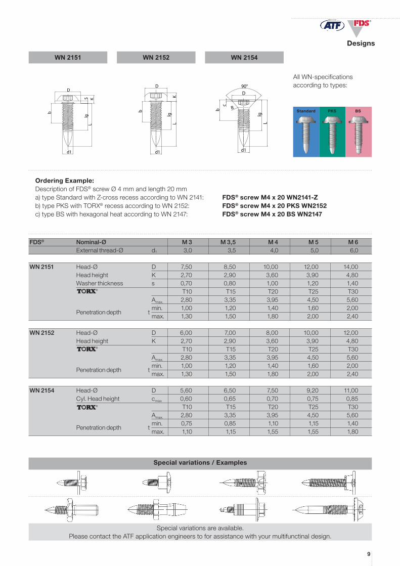
WN 2151 WN 2152 WN 2154
®
®
®
lg
b
d1
DKS
L
d1
b
lgL
D
K
d1
b
L
c
90°D
lg
RStandard PKS BS
Ordering Example:DescriptionofFDS®screwØ4mmandlength20mma)typeStandardwithZcrossrecessaccordingtoWN2141: FDS® screw M4 x 20 WN2141Zb)typePKSwithTORX®recessaccordingtoWN2152: FDS® screw M4 x 20 PKS WN2152c)typeBSwithhexagonalheataccordingtoWN2147: FDS® screw M4 x 20 BS WN2147
AllWN-specificationsaccordingtotypes:
Special variations / Examples
Specialvariationsareavailable.PleasecontacttheATFapplicationengineerstoforassistancewithyourmultifunctinaldesign.
FDS® Nominal-Ø M 3 M 3,5 M 4 M 5 M 6 Externalthread-Ø d1 3,0 3,5 4,0 5,0 6,0
WN 2151 Head-Ø D 7,50 8,50 10,00 12,00 14,00 Headheight K 2,70 2,90 3,60 3,90 4,80 Washerthickness s 0,70 0,80 1,00 1,20 1,40 T10 T15 T20 T25 T30 Amax. 2,80 3,35 3,95 4,50 5,60 min. 1,00 1,20 1,40 1,60 2,00
Penetrationdepth
tmax. 1,30 1,50 1,80 2,00 2,40
WN 2152 Head-Ø D 6,00 7,00 8,00 10,00 12,00 Headheight K 2,70 2,90 3,60 3,90 4,80 T10 T15 T20 T25 T30 Amax. 2,80 3,35 3,95 4,50 5,60 min. 1,00 1,20 1,40 1,60 2,00
Penetrationdepth
tmax. 1,30 1,50 1,80 2,00 2,40
WN 2154 Head-Ø D 5,60 6,50 7,50 9,20 11,00 Cyl.Headheight cmax 0,60 0,65 0,70 0,75 0,85 T10 T15 T20 T25 T30 Amax. 2,80 3,35 3,95 4,50 5,60 min. 0,75 0,85 1,10 1,15 1,40
Penetrationdepth
tmax. 1,10 1,15 1,55 1,55 1,80
Designs
10
®
b
S1
S2
L
Design Recommendations
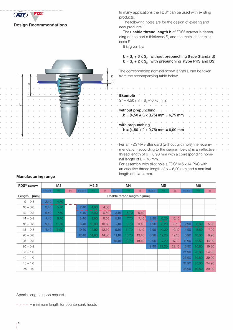
FDS® screw M3 M3,5 M4 M5 M6Standard PKS BS Standard PKS BS Standard PKS BS Standard PKS BS Standard PKS BS
Length L [mm] Usable thread length b [mm]
9+0,8 2,40 4,70
10+0,8 3,40 5,70 2,40 4,90 4,60
12+0,8 5,40 7,70 4,40 6,90 6,60 3,10 5,70 5,40
14+0,8 7,40 9,70 6,40 8,90 8,60 5,10 7,70 7,40 2,90 6,20 6,10
16+0,8 9,40 11,70 8,40 10,90 10,60 7,10 9,70 9,40 4,90 8,20 8,10 2,90 6,60 5,90
18+0,8 11,40 13,90 10,40 12,90 12,60 9,10 11,70 11,40 6,90 10,20 10,10 4,90 8,60 7,90
20+0,8 12,40 14,90 14,60 11,10 13,70 13,40 8,90 12,20 12,10 6,90 10,60 9,90
25+0,8 16,10 18,70 18,40 13,90 17,20 17,10 11,90 15,60 14,90
30+0,8 18,90 22,20 22,10 16,90 20,60 19,90
35+1,0 21,90 25,60 24,90
40+1,0 26,90 30,60 29,90
45+1,0 31,90 35,60 34,90
50+10 36,90 40,60 39,90
InmanyapplicationstheFDS®canbeusedwithexistingproducts.
Thefollowingnotesareforthedesignofexistingandnewproducts.
Theusable thread length bofFDS®screwsisdepen-dingonthepart‘sthicknessS1andthemetalsheetthick-nessS2.
Itisgivenby:
b = S1 + 3 x S2 without prepunching (type Standard)b = S1 + 2 x S2 with prepunching (type PKS and BS)
ThecorrespondingnominalscrewlengthLcanbetakenfromtheaccompanyingtablebelow.
ExampleS1=4,50mm,S2=0,75mm:
without prepunchingb = (4,50 + 3 x 0,75) mm = 6,75 mm
with prepunchingb = (4,50 + 2 x 0,75) mm = 6,00 mm
ForanFDS®M5Standard(withoutpilothole)therecom-mendation(accordingtothediagrambelow)isaneffectivethreadlengthofb=6,90mmwithacorrespondingnomi-nallengthofL=18mm.ForassemblywithpilotholeaFDS®M5x14PKSwithaneffectivethreadlengthofb=6,20mmandanominallengthofL=14mm.
Speciallengthsuponrequest.
=minimumlengthforcountersunkheads
Manufacturing range
1111
®
dD
dD
dW
dV
S1
S2
S1
S2
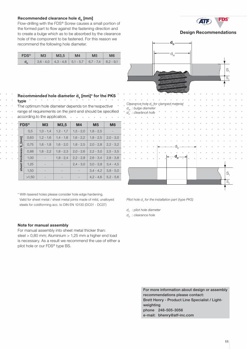
FDS® M3 M3,5 M4 M5 M6
0,5 1,01,4 1,21,7 1,52,0 1,82,5
0,63 1,21,6 1,41,8 1,62,2 1,82,5 2,03,0
0,75 1,61,8 1,62,0 1,82,5 2,02,8 2,23,2
0,88 1,82,2 1,82,3 2,02,6 2,23,0 2,53,5
1,00 1,82,4 2,22,8 2,63,4 2,83,8
1,25 - 2,43,0 3,03,8 3,44,5
1,50 - - - 3,4-4,2 3,8-5,0
>1,50 - - - 4,2-4,6 5,2-5,6
Recommended clearance hole dD [mm]Flow-drillingwiththeFDS®Screwcausesasmallportionoftheformedparttoflowagainstthefasteningdirectionandtocreateabulgewhichastobeabsorbedbytheclearanceholeofthecomponenttobefastened.Forthisreasonwerecommendthefollowingholediameter.
FDS® M3 M3,5 M4 M5 M6
dD 3,64,0 4,34,8 5,15,7 6,77,4 8,29,1
Recommended hole diameter dV [mm]* for the PKS typeTheoptimumholediameterdependsontherespectiverangeofrequirementsonthejointandshouldbespecifiedaccordingtotheapplication.
*Withlaseredholespleaseconsiderholeedgehardening.
Validforsheetmetal/sheetmetaljointsmadeofmild,unalloyed
steelsforcoldformingacc.toDINEN10130(DC01-DC07)
Note for manual assemblyFormanualassemblyintosheetmetalthickerthan:steel>0,80mm;Aluminium>1,25mmahigherendloadisnecessary.AsaresultwerecommendtheuseofeitherapilotholeorourFDS®typeBS.
For more information about design or assembly recommendations please contact: Brett Henry - Product Line Specialist / Light-weightingphone 248-505-3056e-mail: [email protected]
Clearance hole dD for clamped materialdW : bulge diameterdD : clearance hole
Pilot hole dV for the installation part (type PKS)
dV : pilot hole diameter
dD : clearance hole
she
et
thic
kn
ess
S2
[mm
]
Design Recommendations
12
®
Assembly Recommendations
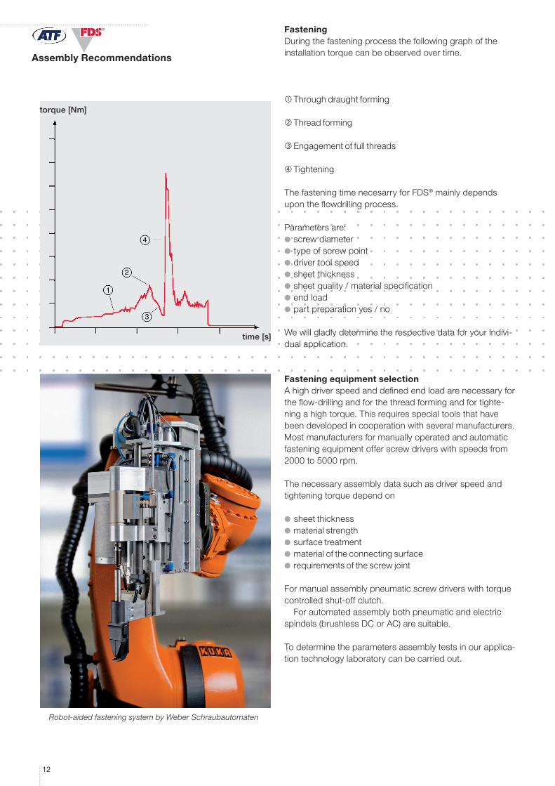
FasteningDuringthefasteningprocessthefollowinggraphoftheinstallationtorquecanbeobservedovertime.
Throughdraughtforming
Threadforming
Engagementoffullthreads
Tightening
ThefasteningtimenecesarryforFDS®mainlydependsupontheflowdrillingprocess.
Parametersare:l screwdiameterl typeofscrewpointl drivertoolspeedl sheetthicknessl sheetquality/materialspecificationl endloadl partpreparationyes/no
Wewillgladlydeterminetherespectivedataforyourindivi-dualapplication.
Fastening equipment selectionAhighdriverspeedanddefinedendloadarenecessaryfortheflow-drillingandforthethreadformingandfortighte-ningahightorque.Thisrequiresspecialtoolsthathavebeendevelopedincooperationwithseveralmanufacturers.Mostmanufacturersformanuallyoperatedandautomaticfasteningequipmentofferscrewdriverswithspeedsfrom2000to5000rpm.
Thenecessaryassemblydatasuchasdriverspeedandtighteningtorquedependon
l sheetthicknessl materialstrengthl surfacetreatmentl materialoftheconnectingsurfacel requirementsofthescrewjoint
Formanualassemblypneumaticscrewdriverswithtorquecontrolledshut-offclutch.
Forautomatedassemblybothpneumaticandelectricspindels(brushlessDCorAC)aresuitable.
Todeterminetheparametersassemblytestsinourapplica-tiontechnologylaboratorycanbecarriedout.
torque [Nm]
time [s]
Robot-aided fastening system by Weber Schraubautomaten

1313
14
®
Properties in use
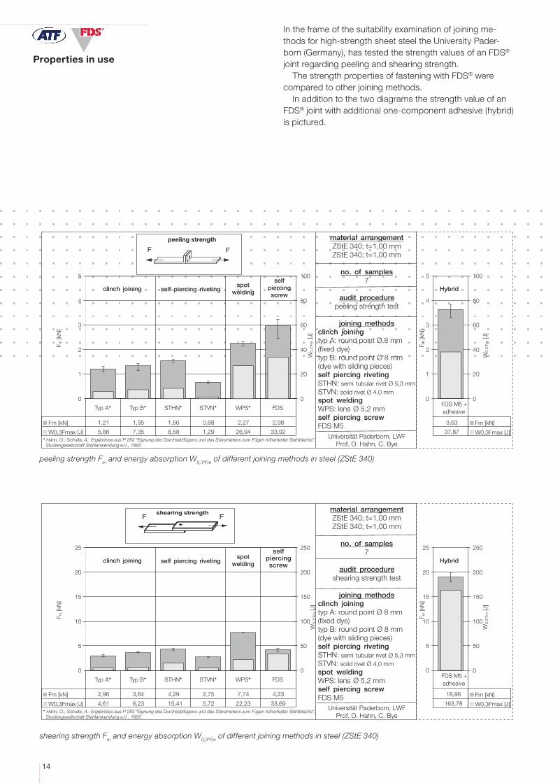
peeling strength Fm and energy absorption W0,3*Fm of different joining methods in steel (ZStE 340)
shearing strength Fm and energy absorption W0,3*Fm of different joining methods in steel (ZStE 340)
Intheframeofthesuitabilityexaminationofjoiningme-thodsforhigh-strengthsheetsteeltheUniversityPader-born(Germany),hastestedthestrengthvaluesofanFDS®jointregardingpeelingandshearingstrength.
ThestrengthpropertiesoffasteningwithFDS®werecomparedtootherjoiningmethods.
InadditiontothetwodiagramsthestrengthvalueofanFDS®jointwithadditionalone-componentadhesive(hybrid)ispictured.
material arrangementZStE 340; t=1,00 mmZStE 340; t=1,00 mm
no. of samples7
audit procedureshearing strength test
joining methodsclinch joiningtyp A: round point Ø 8 mm(fixed dye)typ B: round point Ø 8 mm(dye with sliding pieces)self piercing rivetingSTHN: semi�tubular rivet Ø 5,3 mmSTVN: solid rivet Ø 4,0 mmspot weldingWPS: lens�Ø 5,2 mmself piercing screwFDS M5
Universität Paderborn, LWFProf. O. Hahn, C. Bye
0
5
10
15
20
25
F m [k
N]
0
50
100
150
200
250
W0,
3*Fm
[J]
2,96 3,64 4,29 2,75 7,74 4,23
4,61 6,23 15,41 5,72 22,23 33,69
Typ A* Typ B* STHN* STVN* WPS* FDS
Fm [kN]
W0,3Fmax [J]
clinch joining self piercing rivetingspot
welding
selfpiercingriveting
* Hahn, O.; Schulte, A.: Ergebnisse aus P 283 “Eignung des Durchsetzfügens und des Stanznietens zum Fügen höherfester Stahlbleche”, Studiengesellschaft Stahlanwendung e.V., 1995
18,96
163,78
FDS M5 +adhesive
0
5
10
15
20
25
F m [k
N]
Hybrid
Fm [kN]
W0,3Fmax [J]
0
50
100
150
200
250
W0,
3*Fm
[J]
shearing strengthFF
material arrangementZStE 340; t=1,00 mmZStE 340; t=1,00 mm
no. of samples7
audit procedurepeeling strength test
joining methodsclinch joiningtyp A: round point Ø 8 mm(fixed dye)typ B: round point Ø 8 mm(dye with sliding pieces)self piercing rivetingSTHN: semi�tubular rivet Ø 5,3 mmSTVN: solid rivet Ø 4,0 mmspot weldingWPS: lens�Ø 5,2 mmself piercing screwFDS M5
Universität Paderborn, LWFProf. O. Hahn, C. Bye
0
1
2
3
4
5
F m [k
N]
0
20
40
60
80
100
W0,
3*Fm
[J]
1,21 1,35 1,56 0,68 2,27 2,98
5,86 7,35 8,58 1,29 26,94 33,92
Typ A* Typ B* STHN* STVN* WPS* FDS
Fm [kN]
W0,3Fmax [J]
FF
peeling strength
clinch joining self piercing rivetingspot
welding
selfpiercingscrew
* Hahn, O.; Schulte, A.: Ergebnisse aus P 283 “Eignung des Durchsetzfügens und des Stanznietens zum Fügen höherfester Stahlbleche”, Studiengesellschaft Stahlanwendung e.V., 1995
3,63
37,87
FDS M5 +adhesive
0
1
2
3
4
5
F m [k
N]
Hybrid
Fm [kN]
W0,3Fmax [J]
0
20
40
60
80
100
W0,
3*Fm
[J]
selfpiercingscrew
1515
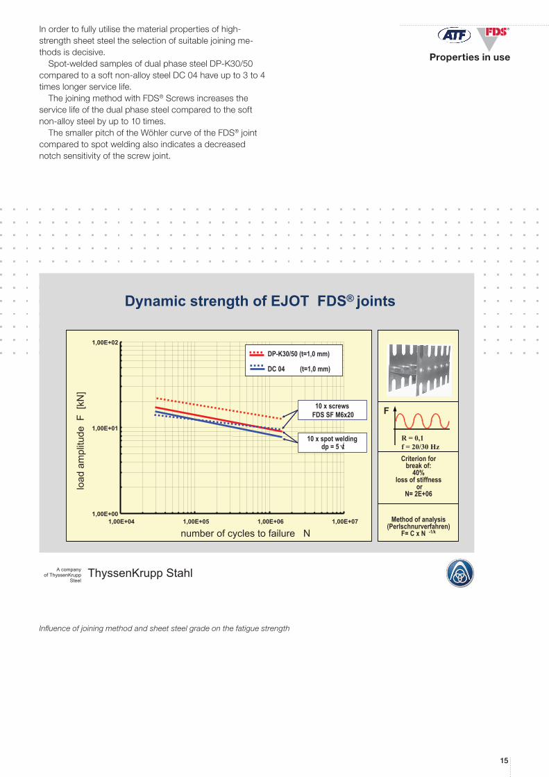
®Inordertofullyutilisethematerialpropertiesofhigh-strengthsheetsteeltheselectionofsuitablejoiningme-thodsisdecisive.
Spot-weldedsamplesofdualphasesteelDP-K30/50comparedtoasoftnon-alloysteelDC04haveupto3to4timeslongerservicelife.
ThejoiningmethodwithFDS®Screwsincreasestheservicelifeofthedualphasesteelcomparedtothesoftnon-alloysteelbyupto10times.
ThesmallerpitchoftheWöhlercurveoftheFDS®jointcomparedtospotweldingalsoindicatesadecreasednotchsensitivityofthescrewjoint.
Influence of joining method and sheet steel grade on the fatigue strength
TK
ThyssenKrupp StahlA companyof ThyssenKrupp
Steel
Criterion forbreak of:
40%loss of stiffness
orN= 2E+06
Method of analysis(Perlschnurverfahren)
F= C x N -1/k
F
H-Scherzugprobe
R = 0,1f = 20/30 Hz
1,00E+00
1,00E+01
1,00E+02
1,00E+04 1,00E+05 1,00E+06 1,00E+07
number of cycles to failure N
load
ampl
itude
F [k
N]
DP-K30/50 (t=1,0 mm)
DC 04 (t=1,0 mm)
10 x spot weldingdp = 5 √t
10 x screwsFDS SF M6x20
Dynamic strength of EJOT FDS® joints
Properties in use
16
®
1. 2. 3.
4. 5. 6.
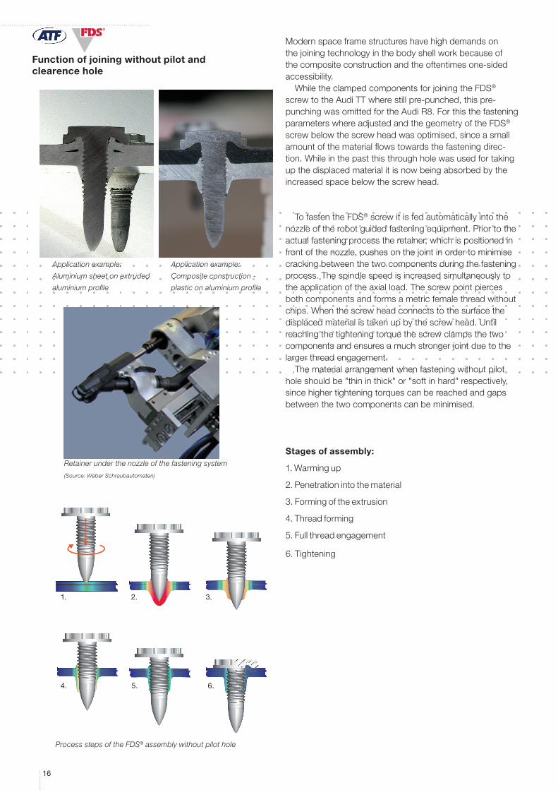
Function of joining without pilot and clearence hole
Modernspaceframestructureshavehighdemandsonthejoiningtechnologyinthebodyshellworkbecauseofthecompositeconstructionandtheoftentimesone-sidedaccessibility.
WhiletheclampedcomponentsforjoiningtheFDS®screwtotheAudiTTwherestillpre-punched,thispre-punchingwasomittedfortheAudiR8.ForthisthefasteningparameterswhereadjustedandthegeometryoftheFDS®screwbelowthescrewheadwasoptimised,sinceasmallamountofthematerialflowstowardsthefasteningdirec-tion.Whileinthepastthisthroughholewasusedfortakingupthedisplacedmaterialitisnowbeingabsorbedbytheincreasedspacebelowthescrewhead.
TofastentheFDS®screwitisfedautomaticallyintothenozzleoftherobotguidedfasteningequipment.Priortotheactualfasteningprocesstheretainer,whichispositionedinfrontofthenozzle,pushesonthejointinordertominimisecrackingbetweenthetwocomponentsduringthefasteningprocess.Thespindlespeedisincreasedsimultaneouslytotheapplicationoftheaxialload.Thescrewpointpiercesbothcomponentsandformsametricfemalethreadwithoutchips.Whenthescrewheadconnectstothesurfacethedisplacedmaterialistakenupbythescrewhead.Untilreachingthetighteningtorquethescrewclampsthetwocomponentsandensuresamuchstrongerjointduetothelargerthreadengagement.
Thematerialarrangementwhenfasteningwithoutpilotholeshouldbe"thininthick"or"softinhard"respectively,sincehighertighteningtorquescanbereachedandgapsbetweenthetwocomponentscanbeminimised.
Stages of assembly:
1.Warmingup
2.Penetrationintothematerial
3.Formingoftheextrusion
4.Threadforming
5.Fullthreadengagement
6.Tightening
Application example:
Aluminium sheet on extruded
aluminium profile
Process steps of the FDS® assembly without pilot hole
Retainer under the nozzle of the fastening system
(Source: Weber Schraubautomaten)
Application example:
Composite construction -
plastic on aluminium profile

17
199/
1.5/
08.1
0
ATF, Inc. 3550 West Pratt Avenue Lincolnwood, IL 60712phone 847-677-1300fax 847-677-9335e-mail: [email protected]: www.atf-inc.com
For addtional information please contact:Brett Henry - Product Specialist / [email protected]