Embed Size (px)
Citation preview

i N A S A C O N T R A C T O R R E P O R T
,
THE FLUID MECHANICS
Everett, Mass. 02 149
for /"
NATIONAL AERONAUTICS AND SPACE ADMINISTRATION WASHINGTON, D. C. JANUARY 1972
https://ntrs.nasa.gov/search.jsp?R=19720007376 2018-07-13T23:57:46+00:00Z

~ "" ~~ ~ . - . I _ . . .
W X H L18RARY KAFB, pdp.1
l~l~llllllllllll~~lll~lll~llll~ill~llllll UDbDse4
1. Report No. NASA CR-1938
2. Government Accession No. 3. Recipient's Catalog NO.
4. Title and Subtitle 5. Report Date
THE FLUID MECHANICS OF THROltBUS FORMATION January 1972 6. PerForming Organization Code
7. Author(s1 8. Performing Organization Report No. """""
. 10. Work Unit No. 9. Performing Organization Name and Address
AVCO Everett Research Laboratory 2385 Revere Beach Parkway Everet t , Massachuset ts 02149
12. Sponsoring Agency Name and Address National Aeronautics and Space Administration T~Jashington, D. C. 20546
11. Contract or Grant No.
NASI-1894 13. Type of Report and Period Covered
Contractor Report 14. Sponxlring Agency Code
RAA
15. Supplementary Notes
16. Abstract
Experimental data are presented for the growth of thrombi (blood c lots) in a s t a g n a t i o n poin t f low of f resh b lood . Thrombus shape , s i ze and s t r u c t u r e are shown t o depend on l o c a l f low conditions. The evo lu t ion o f a thrombus is desc r ibed i n terms of a phys ica l model t h a t i n c l u d e s p l a t e l e t d i f f u s i o n , a p l a t e l e t a g g r e g a t i o n mechanism, and d i f f u s i o n and convection of the chemica l spec ies respons ib le for aggrega t ion . Di f fus ion-cont ro l led and convec t ion- controlled regimes are def ined,by f low parameters and thrombus loca t ion , and t h e c h a r a c t e r i s t i c growth pa t te rn in each reg ime is explained. Quantitative comparisons with an approximate t h e o r e t i c a l model are presented, and a more gene ra l model is formulated.
17. Key Words (Suggested by Authorls) ) 18. Distribution Statement
b io - f lu id mechanics
thrombi formation blood f10t.J
Unc la s s i f i ed - Unlimited
I
19. Security Classif. (of this report)
$3+0 65 Unclassif ied Unclass i f Fed 22. Rice' 21. NO. of Pages 20. Security Classif. (of this page)
For sale by the National Technical Information Service, Springfield, Virginia 22151


TABLE O F CONTENTS
Page
List of Illustrations
I. INTRODUCTION
II. THE EVOLUTION O F A THROMBUS ON A FOREIGN SURFACE
III. THE STAGNATION POINT FLOW EXPERIMENT
IV. THE STAGNATION POINT NON-NEWTONIAN BOUNDARY LAYER
V. THE GROWTH O F A THROMBUS: EXPERIMENT
VL THE GROWTH O F A THROMBUS: THEORY
VIL CONCLUDING DISCUSSION
References
V
1
3
1 1
15
2 1
39
57
59


LIST O F ILLUSTRATIONS
Figure
1 Scanning electron micrograph of an aggregated and unaggregated region.
2 Scanning electron micrograph of the unaggregated region of Fig. 1. Note the density of the individual spread platelets with minimal interaction between them.
3 Scanning electron micrograph of the aggregated region of Fig. 1. Note the density of platelets and small platelet aggregates between the larger major aggregates.
4 Scanning electron micrograph of thrombus in an advanced stage. Note the red cells trapped within the fibrin strands.
5 Schematic diagram of flow chamber in the stagnation point
6 Schematic diagram of a stagnation point flow field, showing non-Newtonian velocity boundary layer and pIatelet diffusi'on layer.
blood flow experiment,
7 Thrombus r lB1f at 21 min. 00 sec. after start of the experiment.
8 Schematic diagram of thrombus growth.
9 Thrombus IIBI1 at 36 min. 30 sec. after start of experiment. Note this photograph is a composite of two photographs taken during the experiment, in order to show the increase in length and width of the thrombus.
10 Thrombus "A" at 19 min. 00 sec.
11 Thrombus "A" at 38 min. 30 sec.
1 2 Growth profile of thrombus "A" a s a function of time. Thrombus initiated at a rad ium ri = 1.40 mm f rom the stagnation point. A = 16.4 sec-1.
1 3 Growth profile of thrombus ltB1l, ri = 0.75 mrn, A = 16.4 sec , -1
Page
5
6
7
9
12
16
22
23
24
25
26
27
28
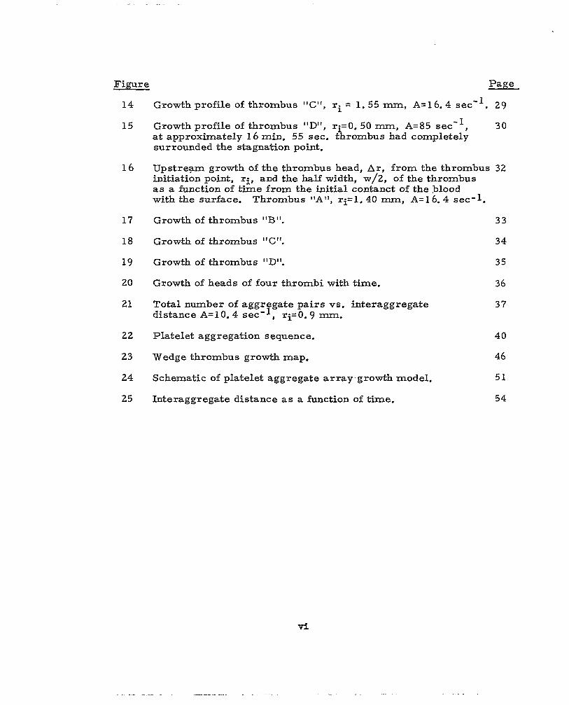
Figure Page
14
15
16
17
18
19
20
21
22
23
24
25
Growth profile of thrombus "C", ri = 1.55 mm, A=l6.4 sec". 29
Growth profile of thrombus "D" , ri=O. 50 mm, A=85 sec , 3 0 at approximately 1 6 min. 55 sec. thrombus had completely surrounded the stagnation point.
-1
Upstream growth of the thrombus head, Ar, f rom the thrombus 32 initiation point, ri, and the half width, w/2, of the thrombus as a function of time from the initial contanct of the .blood with the surface. Thrombus "A", q=l. 40 mm, A=l6. 4 sec-1.
Growth of thrombus " B t t . 3 3
Growth of thrombus "C". 3 4
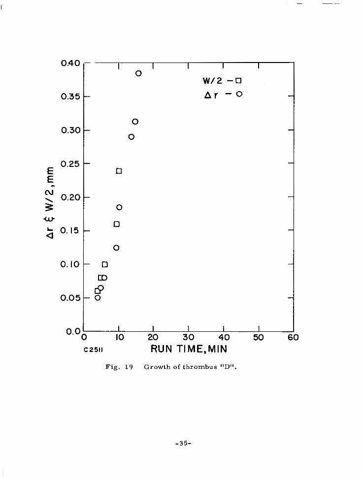
Growth of thrombus "D". 35
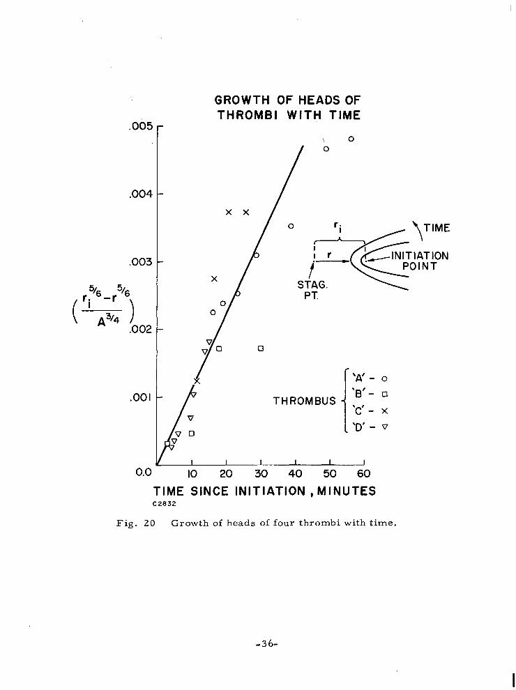
Growth of heads of four thrombi with time. 36
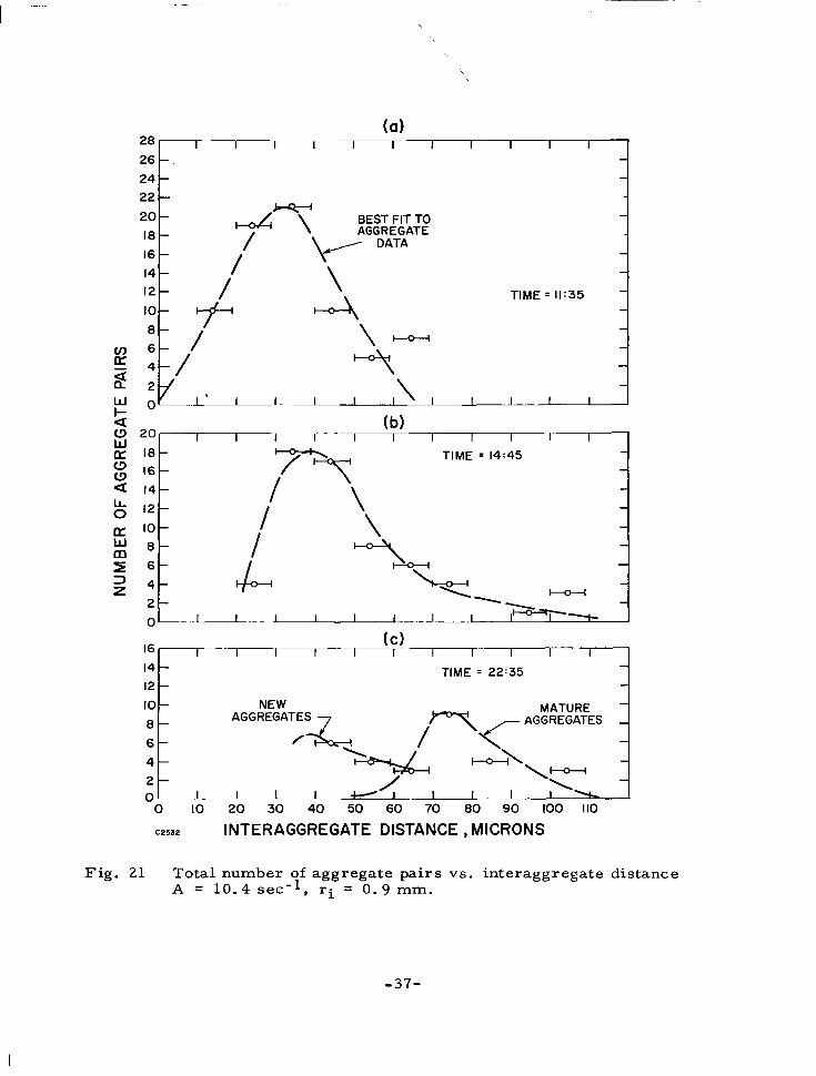
Total number of aggregate pairs vs. interaggregate distance A=10.4 sec'l, ri=O. 9 1111~1. 37
Platelet aggregation sequence. 40
Wedge thrombus growth map. 46
Schematic of platelet aggregate array.growth model. 51
Interaggregate distance as a function of time. 54
v i

I. INTRODUCTION
The coagulation of blood is a complex phenomenon involving bio-
chemistry, surface chemistry, and fluid mechanics. The purpose of this
experimental and theoretical research is to elucidate the influence of the
local flow conditions of the blood on the formation of a thrombus, particu-
larly on artificial surfaces. To give an example of the role played by the
flow, first consider the case of stagnant blood in contact with a foreign
surface such as a tes t tube. The blood solidifies into a red clot by the
formation of a stringy fibrin mesh which entraps the other constituents of
the blood. In contrast to this, when flowing blood contacts a foreign surface
or injured tissue, white solidified masses are observed. These masses,
called thrombi, consist largely of platelets which are cells roughly one
micron in size and occupy about 0. 1% of the volume of whole blood. The
presence of flow indeed has a marked effect on the mechanism by which
blood solidifies in response to external stimuli.
It is generally accepted that high flow rates and high values of shear
at the surface (short of that necessary to damage red cells) tend to minimize
the incidence of thrombosis. Large shear forces on blood elements loosely
attached to the surface may detach these elements before an actual throm-
bus is formed. A second effect is that high flow velocities imply shorter
times in which the blood is in contact with the foreign surface. Some chemi-
cal reactions are required either to cause platelet aggregation or to activate
the coagulation sequence. The.,shorter the residence time of the blood near
the surface the less time is available for these reactions to proceed and,
therefore, one may expect that less thrombus or no thrombus will form
under conditions where the residence time is short. On the other hand, a
mechanism exists by which increased flow tends to lead towards greater
thrombus buildup. In the presence of high surface shears the rate at which platelets diffuse to the surface is increased. Therefore, if the surface is
such that platelets stick on a r r iva l at the surface, a high flow rate would

lead towards a more rapid accumulation of platelets and a rapid growth of
the thrombus. Thus, increased flow could lead to either increased or
decreased thrombosis, depending upon which of the above mechanisms is
dominant. A s will be described later, some evidence for each of these
mechanisms has been observed.
Over the last several years a research program has been carried
out 11-6) to study these fluid mechanical effects both experimentally and
theoretically. A carefully controlled stagnation point flow experiment has
allowed the direct observation of the above factors involved in the growth
of thrombi on a foreign surface. The experimental observations suggest
that diffusion of platelets to the surface, attachment of white cells within a
well-defined radius of the stagnation point, and subsequent platelet aggrega-
tion in the same region are important flow dependent processes at low flow
rates. However, at sufficiently high flow rates platelet aggregation and
thrombus growth occur only at surface imperfections and tend to assume a
characteristic wedge shape with time. A ser ies of observations is presented of the growth history of indivi-
dual thrombi at various radial locations and flow rates. The shape, approxi-
mate thickness, and internal structure have been monitored over a sufficient
range of flow conditions to demonstrate the variety of possible flow dependent
growth patterns. A physical model and scaling parameters for the spatial
and temporal behavior of a thrombus is also presented. A "complete" theo-
retical model, the final objective, remains to be developed. However, sev-
eral clearly important features of the growth process have been modeled
and approximate solutions obtained. Finally, quantitative comparisons with
experimental data have been made where possible, and the more general
analytical model outlined.
The evolution of a thrombus on an artificial surface is discussed in
Section II. The experimental equipment and procedure is described in
Section III. The theory of a stagnation point non-Newtonian boundary layer
is reviewed in Section IV. In Section V the detailed experimental data are
presented for the change of shape, size and structure of thrombi as a func-
tion of time. A general formulation of the theoretical problem is given in
Section VI and the scaling laws derived from these equations are compared
to the data. Section VII is the concluding discussion.
-2 -

II. THE EVOLUTION OF A THROMBUS ON A FOREIGN SURFACE
When fresh blood is brought into contact with an artificial surface,
a very complex chain of events is triggered which differs in numerous
respects from the interaction of blood with its natural container, the blood
vessel walls. In the absence of any disease which might predispose the
blood to some type of hypercoagulability, the walls of the blood vessels have
an antithrombogenic influence on the blood that designers of artificial devices
would be pleased to emulate. When this cell wall (the endothelium) is injured,
physically or chemically, a chain of events occurs which may lead to the
growth of a thrombus. Although there are similari t ies to growth on an
artificial surface, the differences, which have to do with agents released
f rom the injured tissue, are sufficiently profound that the reader is cautioned
not to directly extrapolate our description of the observed growth process to
that occurring on an injured cell wall.
the adhesion of individual platelets to the surface(3). This does not occur
immediately, however, and the small delay time of the order of a minute
is thought to be the time required for a layer of protein to be adsorbed onto
the surface from the blood plasma and modified so that it becomes attrac- tive to platelets. Although the type of surface must have some effect on the
manner in which this layer is deposited, the exact nature of the interaction
is unknown and a mat ter of controversy. A recent study by Friedman,
e t concludes that the platelet deposition rate is not a strong function of
the type of surface, which we also noticed in earlier experiments. This
could be the result of the adsorbed protein layer which physically separates
the surface from the blood.
The first microscopically observable occurrence in the sequence is
The second step is the deposition of a monolayer of platelets on the
surface. The method of adhesion of the platelets to the protein layer is not
known. When the process stops at this step in the sequence, which we have
observed often under some flow conditions, no thrombus forms during the

duration of the experiment.
The third step is platelet aggregation. During this phase the platelets
already on the surface are activated in some manner which causes them to
move together along the surface into clumps. This may be accompanied by
distortion of the platelet cell membrane, e. g. , the platelets swell and extend
outward projections called pseudopodia'" 'I. The peculiar behavior of plate-
lets .during aggregation has been studied a great deal. See, for example,
the other articles in the collections edited by Sherry, et a1 Johnson and Guest'"). Other books of interest on the subject are those by
Marcus and Zucker(13) and the books edited by Kowalski and Niewiarowski
and by Johnson, et a1 . (15)
( lo , 11) and by
(14)
These platelet aggregates are i l lustrated in a ser ies of scanning
electron micrographs in Figs. 1 - 3. The first shows a clear dividing line
between a region of heavy platelet aggregation (aggregates in white) and a
region which is comparatively unaffected. The second micrograph, Fig. 2,
shows individual platelets which have sent out tendril-like pseudopodia but
have not yet aggregated. The la rger ( . - S F > smoother objects are red cells
which were not actually attached to the surface at this point in the experi-
ment and the presence of which is misleading. They appear only because of
incomplete washing of the coverslip. In Fig. 3, the platelets are no longer
individually recognizable and have aggregated into much larger clumps, the
surfaces 03 which appear almost hairy,
Since we do not see platelet aggregates everywhere on the foreign
surface, one might say that the aggregation cannot be simply a matter of
reactivity between the surface and the platelets. However, we observe that
surface imperfections or inhomogeneities (which may be seen optically)
often are the sites of significant platelet aggregation. Complementary to
this is the observation that physical bumps in the surface, but of the same
general material, may significantly disturb the flow and yet not cause aggre-
gation of platelets. One is forced to conclude that some property of the
surface imperfection, whether it be a change in electronegativity or surface
energy or whatever, acts as a triggering mechanism.
The biochemical processes which lead to platelet aggregation have
been studied extensively. Most of these studies are performed on platelets
-4-

PLATELET AGGREGATES
C2506
Fig. 1 Scanning electron micrograph of an aggregated and unaggregated region.
-5-

C2504
Fig. 2 Scanning electron micrograph of the unaggregated region of Fig. 1. Note the density of the individual spread platelets with minimal interaction between them.
- 6-

Fig. 3 Scanning electron.micrograph of the aggregated region of Fig. 1. Note the density of platelets and small platelet aggregates between the larger major aggregates.
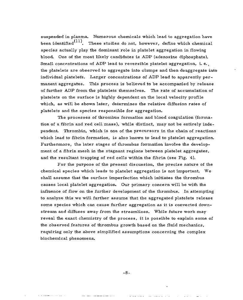
suspended in plasma. Numerous chemicals which lead to aggregation have
been identified'"). These studies do not, however, define which chemical
species actually play the dominant role in platelet aggregation in flowing
blood. One of the most likely candidates is ADP (adenosine diphosphate).
Small concentrations of ADP lead to reversible platelet aggregation, i. e.,
the platelets are observed to aggregate into clumps and then deaggregate into
individual platelet's. Larger concentrations of ADP lead to apparently per-
manent aggregates. This process is believed to be accompanied by release
of further ADP from the platelets themselves. The rate of accumulation of
platelets on the surface is highly dependent on the local velocity profile
which, as will be shown later, determines the relative diffusion rates of
platelets and the species responsible for aggregation.
The processes of thrombus formation and blood coagulation (forma-
tion of a fibrin and red cell mass), while distinct, may not be entirely inde-
pendent Thrombin, which is one of the precursors in the chain of reactions
which lead to fibrin formation, is also known to lead to platelet aggregation.
Furthermore, the later stages of thrombus formation involve the develop-
ment of a fibrin mesh in the stagnant regions between platelet aggregates,
and the resultant trapping of red cells within the fibrin (see Fig. 4).
F o r the purpose of the present discussion, the precise nature of the
chemical species which leads to platelet aggregation is not important. We
shall assume that the surface imperfection which initiates the thrombus
causes local platelet aggregation. Our primary concern will be with the
influence of flow on the further development of the thrombus. In attempting
to analyze this we will further assume that the aggregated platelets release
some species which can cause further aggregation as it i s convected down-
stream and diffuses away from the streamlines. While future work may
reveal the exact chemistry of the process, it is possible to explain some of
the observed features of thrombus growth based on the fluid mechanics,
requiring only the above simplified assumptions concerning the complex
biochemical phenomena.
-8-

Fig. 4 Scanning electron micrograph of thrombus in an advanced stage. Note the red cells trapped within the fibrin strands.
-9 -

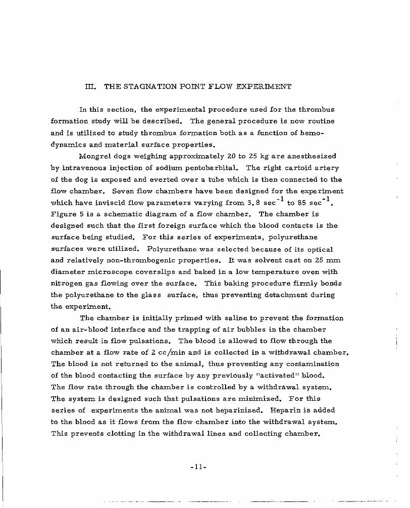
III. THE STAGNATION POINT FLOW EXPERIMENT
In this section, the experimental procedure used for the thrombus
formation study will be described. The general procedure is now routine
and is utilized to study thrombus formation both as a function of hemo-
dynamics and material surface properties.
Mongrel dogs weighing approximately 20 to 25 kg are anesthesized
by intravenous injection of sodium pentobarbital. The right cartoid artery
of the dog is exposed and everted over a tube which is then connected to the
flow chamber. Seven flow chambers have been designed for the experiment
which have inviscid flow parameters varying from 3.8 sec" to 85 sec-l.
Figure 5 is a schematic diagram of a flow chamber. The chamber is
designed such that the first foreign surface which the blood contacts is the
surface being studied. For this series of experiments, polyurethane
surfaces were utilized. Polyurethane was selected because of its optical
and relatively non-thrombogenic properties. It was solvent cast on 25 mm diameter microscope coverslips and baked in a low temperature oven with
nitrogen gas flowing over the surface. This baking procedure f i r m l y bonds
the polyurethane to the glass surface, thus preventing detachment during
the experiment.
The chamber is initially primed with saline to prevent the formation
of an air-blood interface and the trapping of air bubbles in the chamber
which result in flow pulsations. The blood is allowed to flow through the
chamber at a flow ra t e of 2 cc/min and is collected in a withdrawal chamber.
The blood is not returned to the animal, thus preventing any contamination
of the blood contacting the surface by any previously "activated" blood.
The flow rate through the chamber is controlled by a withdrawal system.
The system is designed such that pulsations a r e minimized. For this
s e r i e s of experiments the animal was not heparinized. Heparin is added
to the blood a s it flows from the flow chamber into the withdrawal system.
This prevents clotting in the withdrawal lines and collecting chamber.
-11-

MICROSCOPE COVER SLIP
DARK FIELD LLUMINATION \ \
\
I - ARTERY EVERTED OVER TUBING
CAROTID ARTERY,
A9067
t MICROSCOPE
rR STAGNATION REGION
r h I 1
(I P t FLOW
BLOOD REGULATOR
Fig . 5 Schematic diagram of flow chamber in the stagnation point blood flow experiment.
-12-

During the experiment, the blood-polyurethane surface is continually
observed by dark field reflected microscopy. The location of the stagnation
point and any thrombi which form are noted. When a thrombus is observed,
its growth is documented by visual observations, 35 mm photographs, and
16 mm movies. Time at which flow distortion begins to occur , reverse o r
la te ra l flow, and red cell trapping are observed visually. Approximate
aggregate depth is obtained by utilizing a 22 X objective lens and a micro-
meter scale on the focus adjustment of the microscope. The lens is first
focused on the blood-polyurethane surface, and then focused through the
aggregates on the blood cells flowing over the aggregates.
Local white cell velocity data and thrombi growth profiles are obtained from the 16 mm movies. Profiles and interaggregate distance are
also obtained from 35 mm slides.
A t the conclusion of the experiment, the dog is sacrificed and the
coverslips are stained with Wrights stain and examined.
-13 -

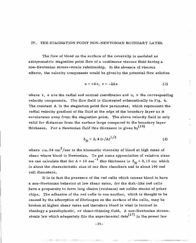
IV. THE STAGNATION POINT NON-NEWTONIAN BOUNDARY LAYER
The flow of blood on the surface of the coverslip is modeled as
axisymmetric stagnation point flow of a continuous viscous fluid having a
non-Newtonian stress-strain relationship. In the absence of viscous
effects, the velocity components would be givenby the potential flow solution
u = t A r , v = -2Az (1)
where r, 2; are the radial and normal coordinates and u, v the corresponding
velocity components. The flow field is illustrated schematically in Fig. 6. The constant A is the stagnation point flow parameter, which represents the
radial velocity gradient of the fluid at the edge of the boundary layer as it accelerates away from the stagnation point. The above velocity field is only
valid for distances from the surface large compared to the boundary layer
thickness. For a Newtonian fluid this thickness is given by (16)
6, = 2.4 (v/A) 1 / 2
where V_N. 04 cm /sec is the kinematic viscosity of blood at high rates of
shear where blood is Newtonian. To ge t some appreciation of relative sizes
we can calculate that f o r A = 10 sec-' this thickness is 6 = 0.15 cm which
is about the characteristic size of our flow chambers and is about 190 red
cell diameters.
2
N
It is in fact the presence of the red cells which causes blood to have
a non-Newtonian behavior at low shear rates, for the disk-like red cells
have a propensity to form long chains (rouleaux) not unlike stacks of poker
chips. The adhesion of the r ed cells to one another, which is thought to be
caused by the adsorption of fibrinogen on the surface of the cells, may be
broken at higher shear rates and therefore blood is what is termed in
rheology a pseudoplastic, or shear-thinning fluid. A non-Newtonian s t r e s s -
strain law which adequately fits the experimental data(17) is the power law
- 15-

Z
C IO45
. . . . - - POTENTIAL FLOW
. . . . / / / / / / / / / / / /
AN
- r LEDGE OF PLATELET B. LAYER
Fig. 6 Schematic diagram of a stagnation point flow field, showing non-Newtonian velocity boundary layer and platelet diffusion layer.
where T is the shear s t ress , au/a z the rate of strain and K, N are
constants. Blood of normal hemocrit (45% red cells by volume) m a y b e
represented (18' 19, by the values N = 4/5, K = 0.1 in cgs units. Cor-
respondingly, one may consider blood to have a rate of strain dependent
viscosity of p = 0.1*,(au/a gm cm sec '. The above approxima-
tions should be adequate for the boundary layer analysis which follows.
-1 -
The axisy-mrnetric stagnation point boundary layer equations are
pu a U/a r t pv a u / az = a T / a z - a p / a r (4)
a U/a r + u / r t a v / a z = o (5)
for the conservation of radial momentum and conservation of mass. The
shear stress is given by Eq. (3 ) and the pressure gradient is ap/a r = -PA r
f r o m the irrotational flow represented by Eq. (1). It is convenient to non-
dimensionalize all the lengths and velocities by the reference length
Q = (v R/A)1/2 and the velocity U = (v RA)1/2 where v i s a reference
viscous diffusivity to be chosen momentarily and A is the stagnation point
flow parameter. Letting
2
(cy = (u/U, V/U); (iy E) = (r/Q ./I 1 we have for the dimensionless conservation equations
N- 1 u ~ u + + a~ = " - 2 - a t i
a ? a 2 - - a G u a 3
a s I a B + - + - = o
i f the reference kinematic viscosity is chosen as
- NK AN-'
P v R -
- 17-

The proper nondimensionalizing length and velocity are then
1 / 2 1 /2
P = ( NK AN-2 ) , u = ( NK A N,
The above system of partial differential equations, ( 7 ) and (8), m a y be
reduced to one ordinary differential equation in one independent variable
using the similarity transformation implied by the following equations 1 -N
- - q = z r l+N
;= I $ 1 (q)
The differential equation is
with the boundary conditions
$ (0) = $ (0 ) = 0, $ ' (") = 1 (15)
The numerical solutions t o ( 1 4 ) may be found in Ref. 20 where $ (q ) and
$ I (0 ) are tabulated for various values of N.
The velocity gradient and the shear stress at the surface are given
in physical coordinats for a non-Newtonian fluid by 1
The relevant constants that have not yet been given are $.I ( 0 ) w 1. 25 for
any N near unity and p = 1 . 0 6 gm/cm . 3
- 18-

F o r a Newtonian fluid, the shear at the surface can be shown to increase as the 3/2 power of the flow parameter, A, and to increase
linearly with distance from the stagnation point. Thus, for a given flow
parameter, the shear is zero at the stagnation point and increases as one
moves outward. The shear at any given distance from the stagnation
point is larger the higher the flow parameter. The radius at which a given
shear is reached decreases as the 3/2 power of the flow parameter. Thus,
for a situation in which local shear is the significant parameter, one would.
expect similar phenomena to occur at radii which decrease with increasing
flow as the 3/2 power of the flow parameter. For some of the results to be
described later, the departure of blood f rom a Newtonian viscosity is
significant. In this case the shear still increases with radial distance from
the stagnation point. However, its variation with distance is different. It
can be shown,' however, based on an analysis of non-Newtonian stagnation
flow, that the radius at which a given shear is reached still scales as the
inverse 3/2 power of the flow parameter.
For comparison to experiment it is useful to approximate the velocity
profile in this thin viscous layer as a l inear variation with the distance z
away from the surface. In the viscous l a y e r then
u = p r z
where we have defined a convenient parameter p = (au/a z) r- . 1 W
The parameter f3 is theoretically well defined only for the ideal
stagnation point flow, the streamlines of which a r e hyperbolic in shape as
shown in Fig. 6. Since the flow in the experimental flow chambers does
not correspond exactly t o this ideal, the parameter p has been measured
empirically. This also allows the determination of an effective. inviscid
stagnation point flow parameter, A, for a given flow rate of blood through
a given chamber.
This discussion of the velocity field in the flow experiment forms a
framework for the following presentation of the data taken on the growth of
thrombi.
- 19-

"

V. THE GR-OWTH O F A THROMBUS: EXPERIMENT
Numerous experiments have been carried out according to the
procedure outlibed in Section III. The data to be presented here have been
selected as typical of the numerous thrombi we have observed. Other data
were rejected for various reasons, e. g., some thrombi could not be
observed over a long enough time interval or over a la rge enough area ;
others occurred so close together in one run that their growth was dom-
inated by mutual interference effects. The four thrombi (Labeled A, B, C,
D) which we show he re are the best documented examples.
The photographs of the four thrombi are black and white reproductions
of single frames of the color movies taken through the optical microscope.
The first photograph, Fig. 7, shows thrombus B at a very ear ly s tage.
What can be seen as a faint airfoil shape is the region of platelet aggregation
and white cells in the wake of the point of initiation. A schematic picture of
the growth of the region of platelet aggregation with time is furnished in
Fig. 8. A picture of the same thrombus at a later intermediate t ime is given
in Fig. 9. Note the swept back wedge-like shape of the thrombus and the
mottled appearance and nonuniform nature of the platelet aggregation. The
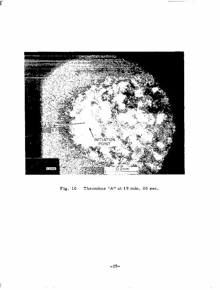
picture of thrombus A in Fig. 10 clearly shows the characterist ic shape of the head or leading edge of the wedge thrombus, and the initiation point
(a surface imperfection) shows up as a bright spot. The last photo of throm-
bus A in Fig. 11 shows the shape at a later time when the growth has been
greatly influenced by the radial nature of the flow. The radius of curvature
of the indentation of the head of the thrombus is nearly equal to the radius
from the stagnation point. Some thrombi, such as thrombus D, eventually
grow to envelop the stagnation point, and thereafter rapidly cover the entire
surface.
Quantitative data chronicling the growth history of the thrombi are
presented in three ways. First, in Figs. 12-15 the outlines of the greatest
extent of the platelet aggregation as perceived visually are given as a
-21-

.
. -.
I 0.2 mm 1 ' I
( A )
Fig. 7 Thrombus I'B"'at 21 min. 00 sec. after start of the experiment.
- 22-

IN ITlATlON POINT
AT RADIUS ri FROM - STAGNATION POINT
FTHROMBUS
STAGNATION POINT
C2530
Fig. 8 Schematic diagram of thrombus growth.
- 23-

Fig. 9 Thrombus I l B l l at 36 min. 30 sec . a f te r start of experiment. Note this photograph is a composite of two photographs taken during the experiment, in order to show the increase in length and width of the thrombus.
- 24-
r
Fig. 1 0 Thrombus "A" at 19 min. 00 sec.

F i g . 1 1 Thrombus "A" at 38 min. 30 sec.
-26 -

H 0.1 mm
t = 56:45 MIN 28: 30
23:OO
'i " /--
c 2499
Fig . 12
56.45 28: 30 " "
16: 00
Growth profile of thrombus "A" as a function of time. Thrombus initiated at a radium ri = 1 .40 mm from the stagnation point. A = 1 6 . 4 sec-l.
- 27-

C 2507
- 36:30
MIN.
Fig. 1 3 Growth profile of thrombus "B", ri = 0. 75 mm, A = 1 6 . 4 sec- 1 ,
- 28-

t .
/ /
/ /
/
C 2513
Fig . 14 Growth profile of thrombus ttC" , r i = 1.55 mm, A = 16 .4 s ec - l .

1655
C2508
EVOLUTION OF THROMBUS SHAPE
H 0.1 mm
4:OOMIN
I4 :55
Fig. 15 Growth profile of thrombus 'ID", r i = 0. 50 mm, A = 85 sec-I, at approximately 16 min. 55 sec. thrombus had completely surrounded the stagnation point.
- 30-

function of t ime for each of the four thrombi. Secondly, data on the growth of
the head toward the stagnation point and on the width of the head is presented in Figs. 16-19. These measurements are i l lustrated in the schematic of
Fig. 8. In Fig. 20 we have graphed the thrombus head position as a function
of time for the four thrombi grown under different flow conditions. The third set of data is given in Fig. 2 1 and represents statistics on the inter-
aggregate spacing in a thrombus as a function of distance from the stagnation
point and time. The data is presented in the form of histograms of measured interaggregate distances at three times during the experiment. A "best f i t "
curve is drawn through the total set of measurements at each time.
It is clear that a theoretical description of these effects must con-
sider the transport to the surface of molecular and cellular matter suspended in the blood as well as the surface reactions. The characteristic size, shape and structure of the wedge thrombi discussed above are qualitatively well
understood in terms of the model which is formulated in the following section.
-31-
I

0.55 - I I I I I 0
0.50 - -
0.45 - -
0.40 - -
0.35 - - 0
E E 0.30- N-
3 G 0.25 -
0
- \
- a L.
0.20 -
0.15 - -
0.10 - -
0.05 - -
0.0 0 I I I I I I O 20 30 40 50 60
C2500 RUN T I ME, MIN
0
0
0
0 0
0 0 0
0
w/2 - 0 A r - 0
F i g . 16 Upstream growth of the thrombus head, A r , from the thrombus initiation point, ri, and the half width, w/2, of the thrombus as a function of time from the initial contact of the blood with the surface. Thrombus " A t t ; r i = 1 .40 mm, A = 16 .4 s e c - l .
- 32-

0.30
0.25
€ E cu \ 0.15
0.20
L
3
: 0.10
0.0 5
0 .o
0
0
0 0
IO 20 30 40 50 60 C2509 RUN TIME,MIN
F i g . 17 Growth of thrombus "El".
- 33-

0.25 0*301 € E - 0.20 cu
0
0
0 w / 2 -0 A r -0
0 0
0
0
0.10 -
0.05 -
o.oo I 1 IO 20 30 40 50 60 C2510 RUN TIME,MIN
0 1 F i g . 1 8 Growth of thrombus "C".
- 34-
0.4 0
0.3 5
0.30
E 0.25
cu \ 0.20
a 0.15
0. IO
0.0 5
0 w / 2 -0
A r - 0
0
0
0
0
0
0
c 2511 RUN TIME,MIN
Fig. 1 9 Growth of thrombus "Dl'.
-35-
GROWTH OF HEADS OF THROMBI WITH TIME
-Oo5 r \ 0
.004
.003
5/6 5/6 -r
( ri A3/4 ) .002
c
/ ~
I AT ION POINT
.oo I C P
0.0
THROMBUS ‘9’- o ‘c’ - x
I I I I I
IO 20 30 40 50 60 TIME SINCE INITIATION , MINUTES C2832
Fig . 20 Growth of heads of four thrombi with time.
- 3 6 -
\
17 l 4 t i
a 0 Lr.
6
4 I 0' 1 I 1 I I I
14
6 4
n
TIME = 2 2 ~ 3 5 4 MATURE
1 I - l " - 0 IO 20 30 40 5 0 60 70 80 90 100 110
C2532 INTERAGGREGATE DISTANCE, MICRONS
-37-


VI. THE GROWTH O F A THROMBUS: THEORY
Part I - Early and Intermediate Time In the section describing the evolution of a thrombus, a two-part
mechanism of platelet aggregation and accumulation is postulated which
utilizes the concept of an activating species which is contained in the platelets themselves. When a platelet encounters a critical concentration
of this species near the surface, it sticks to the surface and joins in the
aggregation, in which process more of the species is released to activate
other platelets. This process is graphically described in the flow chart of
Fig. 22. The growth of the aggregate can be limited only by a shortage in the re lease rate of the activating species or a shortage in the arrival rate
of platelets. Now, we would like to quantify these concepts in the con-
struction of a mathematical model capable of describing the features of
thrombus growth which have been documented in Sec. V.
The platelets are the dominant constituent in the thrombi we observe.
We shall derive a conservation equation for them presently. Before doing
this, however, we must give attention to the dominant transportation mech-
anism for such macroscopic particles. In Ref. 3 , several mechanisms for
platelet transport to the surface a re considered. It i s shown that direct
impingement of the platelets as they are car r ied by the flow to the surface
along streamlines is a negligible contribution to the platelet arrival rate
and is inadequate to explain observed platelet growth. Similarly, because the platelet is so large compared to molecular species, the diffusion by
Brownian motion is v e r y small. The random diffusion coefficient for plate-
lets is roughly c m /sec. compared to -10 cm / sec for low molecular 2 -5 2
weight species, and hence the f l u x of particles by ordinary diffusion is very
small.
The important transport mechanism is redcell augmented diffusion. The shearing motion of the velocity gradient in the boundary layer causes
the red cells, both as individuals and in rouleaux, to twnble at a rate pro-
portional to the velocity gradient. The velocity perturbations caused by
- 3 9 -

SURFACE FIRST EXPOSED +
PROTEIN LAYER AGGREGATION ADSORBED ON
PLATELET
SEQUENCE SURFACE
'1 PLATELETS ADHERE TO SURFACE, RELEASING ACTIVATING SPECIES IN DIFFERENT AMOUNTS FOR DIFFERENT STIMULI
I I I NEW PLATELETS STICK,
DEFORM, AGGREGATE AND RELEASE MORE ACTIVATING
SPEC1 E S
DOES ACTIVATING SPECIES CONCENTRATION ARRIVING PLATELETS
EXCEED SOME CRITICAL DONOT ADHERE VALUE ?
GROWTH CONTINUES
I
t I
PRESENT TO BE
v GROWTH STOPS DUE
TO LIMIT ON ARRIVAL RATEOFNEWPLATELETS
C2569
Fig. 22 Platelet aggregation sequence.
-40-

these rotating disk-like cells result in a significant enhancement in the
mixing rate, not unlike turbulence in nature. The essential effect of the velocity perturbations induced by the red cells rotating in response to the
velocity gradient is to make the augmented diffusion coefficient also pro-
portional to the velocity gradient. The first order effects of red cell tumbling will be estimated with
a fairly elementary model. Due to the velocity gradient (au/a z ) in the boundary layer, a red cell rotates about its diameter with an average
angular velocity 0 = - - a u as required by a zero net torque on the particle, The velocity field consists of two components; one due to un-
bounded shear flow, and one due to particle rotation. Representing the
rotating red cell as a sphere of radius b, the latter perturbation decreases with distance (13) as - (b / r ) , whereas the former varies as-(b/r) . F o r dilute suspensions (low hematocrit), the only long-range effect is due to
red cell rotation, and the effects of red cell interactions are also negligible.
Completely random interactions between the small particles (platelets) and
the red cell velocity fields will be assumed, with a characteristic frequency
f and “mean f ree t ime” t given by the relative velocity A u and average dis-
tance r r between the red cell and particles:
2 a z ’
2 4
1 f E - = - A u
t A. r
hence
Furthermore, L\r - 1/2 C1/3, where C is the number density of red cells. Finally, the characteristic velocity perturbation is q ’ N ob (b /2 A r ) . Now,
for a Itrandom walkft process, the ”mean free path’’ X -(Dt)1/2 where D i s
the diffusivity. Since X - q t t as well ,
- 2
2 D-(q’)t-.8w2b2(b/2 z)4
or D -4b c ~ / ~ a U/a z
-41 -

Finally, in terms of the volumetric concentration c P’
D - b Gp 2 4/3 a U/a z
with the constant of proportionality expected to be of the order one.
The above result is an estimate which is valid, at best, at low
hematocrit, for unbounded flows, and small red cell Reynolds number.
In Ref. 21 it is shown that this derived diffusion coefficient is a
good approx.imation to data taken in a simulation experiment using neutrally
buoyant spheres in a pipe flow geometry even at moderately high particle
concentrations, velocity gradients and particle Reynolds number.
At very low shears this type of diffusion coefficient is inappropriate
because the red cells form rouleaux, i. e. , they cling together in long chains
resembling a stack of poker chips. The diffusion coefficient varies as the
square of the largest radius of the particle, so that an increase in particle
(rouleaux) length with decreasing shear will reduce the dependence of the
diffusion coefficient on the shear.
A of rouleaux formation that appears to correlate blood
viscosity data at low shear yields the following expression for the length to
diameter ratio J:
J b - ( s ) - 1/2
A diffusion coefficient limit at very small shear rates is then obtained:
For normal blood, then
D - 1.5 x as au/a z - o
-42 -

As shear rate increases , J -1, and the previous result is obtained. A
reasonable matching point is at au/a z = 1.0, so that
and
The equation expressing the conservation of platelets is the usual steady state boundary layer species conservation equation, which is written a s
where C is the volumetric concentration of platelets-and u ,v are the local
velocity components in the momentum boundary layer which are given in
Sec. IV. Azimuthal and radial diffusion terms have been dropped as being small compared to the normal diffusion, and the term involving an azimuthal
velocity will not be present until the thrombus is large enough to appre-
ciably distort the flow. There are no production or loss t e rms in this equa-
tion because the only loss of platelets is at the bounding surface. The outer
boundary conditions are that the concentration of platelets assumes the free
stream value on the axis and at the edge of the boundary layer
P
lim c ( r = O , 2) = CP,’ zlarge p P C ( r , z ) = C
P*
The surface boundary condition we shall leave for later consideration. In Ref. 2, a similarity solution to Eq. (21) is obtained in order to
get the f l u x of platelets driven to the surface by the augmented diffusion.
This flux can be shown to be, for a Newtonian boundary l a y e r and M = 1
-43-

F = Dp 1% I platelets W 2 c m s e c
W
The rate of growth of the thrombus in the z direction can be estimated
then to be - - - (flux of platelets to thrombus) (volume of platelet) dh dt
= F (4 x 10 c m ) -12 3 W
(24)
= (8 x A5l3 ( r , c m ) c cm/sec Po3
For thrombus C, a.nd A = 17 s e c , r = 0. 1 5 5 c , and C = 4.6 x -1
1 0 c m . The ra te of increase of height of the thrombus is 5 x?O cm/sec
o r 3 microns/min. The estimates of observed thickness indicate a smaller
ra te of growth, like one micron per minute. The’halfwidth of thrombus C
grew at a ra te of about 15 microns/min, however. (See Fig. 18). Since
the growth rate calculated should be the maximum rate of accumulation of
platelets, it is apparent that the rate of platelet aggregation is probably not
limited by platelet arrival rate but rather by the diffusion of activating species.
r 3 p . -6
The equation for the conservation of an activating species has a simi-
lar form, only now the diffusion in each of the three directions can be of the
same magnitude, so the equation has the form.
-44-

where C is the volumetric concentration of activating species and D is the a a corresponding diffusion coefficient, which will be taken to be a constant. We
may not, in general, omit the time dependent term here because the concen-
tration contours follow the thrombus surface quite closely and the thrombus growth time history is what we seek. The outer boundary conditions for Ca
' a r e that Ca vanishes for large distances from the thrombus in each direction. The initial condition is that Ca vanishes everywhere initially, except at the
initiation point of the thrombus (r = r 8 = 0) , at which point it has some i' given value which is greater than a critical concentration for platelet aggre-
gation. The phenomenon of the thrombus exuding a particular species which
in turn diffuses into and is convected by the boundary layer flow has several interesting features. One can best discuss the various regimes of interest
in a coherent manner by reference to the Thrombus Growth Map in Fig. 23.
The various shapes of thrombi in a stagnation point flow are illustrated. For early time and for radii of the same size or smaller than a diffusion
length, the thrombus is diffusion dominated and will tend to have near equal
lateral and radial dimensions. For large flow parameters or for points of initiation large compared to a diffusion length, the thrombus is convection dominated and a.ppears to have a very swept-back shape.
We can get an estimate of the velocity of the thrombus edge growth (the moving platelet aggregation front) in the following way. Assuming that
the thrombus is exuding the activating species, at some time 7 the locus of the contour of constant critical concentration of this species is assumed to be
at a distance 6 from the current thrombus position. The thickness of this diffusion layer must depend on a balance between the diffusion perpendicular to the layer and the velocity component perpendicular to the thrombus edge.
A good estimate of the size of this diffusion layer is
cjz =a u( r , z) cos a
where a is the angle between the direction of the boundary layer velocity
vector and the thrombus edge normal. There is a question as to what vecocity to use here, i. e. , how far up into the velocity boundary layer does
-45 -
I

Fig. 23 Wedge thrombus growth map.
-46-
this diffusion process extend? It must be of the same order as the sideways
diffusion, s o we evaluate the velocity in the boundary layer at a height equal
to 6. W e shall use
u(z = 6) = - 6 = a u Ar 4 ' ' (0) 6 a Z
for the velocity in the boundary layer in the previous formula for diffusion
thickness. Solving for 6 then gives
1 / 2 D D v =(e c: a ) 4 ' ' (0)r cos a
a ( 2 8 )
This is a measure of the distance in which the diffusion front moves
in the time - cos a and defines the region within which the concen-
tration of activating species is above some critical level. This region will march forward in time as platelets arrive within the region, stick, and
re lease more of the species. W e can estimate the characteristic time T
for the surface to collect a particular surface density of platelets by making
the ratio of the flux to the wall of platelets to the surface density of platelets. This surface density should properly be that necessary to release the criti- cal concentration of the activating species. This would be a very interesting
number to derive from the measured growth velocity data once this simple model is complete. Then
( E ) - l
is a fair estimate of the characteristic time to deposit a particular surface
density of platelets.
-47 -
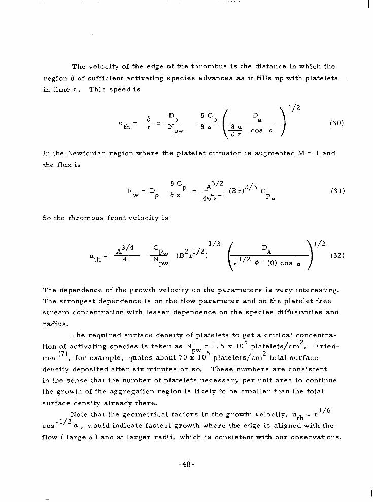
The velocity of the edge of the thrombus is the distance in which the
region 6 of sufficient activating species advances as it fills up with platelets
in time 7 . This speed is
In the Newtonian region where the platelet diffusion is augmented M = 1 and
the flux is
So the thrombus front velocity is
A3/4 C Da - uth - 4 N 1 / 2 )'I2 (32)
PW V 9" ( 0 ) cos a
The dependence of the growth velocity on the parameters is very interesting.
The strongest dependence is on the flow parameter and on the platelet f r ee
stream concentration with lesser dependence on the species diffusivities and
radius.
The required surface density of platelets to get a critical concentra-
tion of activating species is taken as N = 1. 5 x 1 0 platelets/cm . Fried-
man(7), for example, quotes about 70 x 10 platelets/cm total surface
density deposited after six minutes or so. These numbers are consistent
in the sense that the number of platelets necessary per unit area to continue
the growth of the aggregation region is likely to be smaller than the total
surface density already there.
5 2
pw 5 2
Note that the geometrical factors in the growth velocity, uth- r 1 /6 cos -'I2 a , would indicate fastest growth where the edge is aligned with the flow ( large a ) and at larger radii, which is consistent with our observations.
-48-

The expression for the thrombus growth velocity in (32) should
collapse the data taken for the four thrombi at different flow conditions. Taking u - dr/dt and integrating to find the front position versus time, th - r(t), we get
The factors on the right hand side of the equation are fixed constants for any blood sample. The factors on the left side are the scaling factors for throm- bus position as a function of time and angular position for different flow
parameters. In Fig. 20 we have graphed the thrombus head position as a function
of time for the four thrombi grown under different flow conditions. The agreement is excellent considering the uncertainties in the concentrations
and diffusivities. Part 11: Late Time
The asymptotic structure of a growing wedge thrombus is chara,cteri-
zed by a large number of well define platelet aggregates. As seen in Figs .
9, 10 and 11, the aggregates form in the wake of the initial disturbance
(thrombus head) and grow with time. As they grow, their total number decreases, and the interaggregate distance increases. Thus, the ratio of
aggregate size to separation distance appears to be fairly constant with time, and the characteristics aggregate dimensions apparently "scale" with throm- bus size. Since aggregate growth has been shown(3) to be due primarily to
platelet diffusion induced by red cell tumbling, it is possible that this mech-
anism is also responsible for the observed aggregate geometry. An aggre- gate's growth is enhanced at its peak and reduced in the valleys hetween aggregate^'^), due to the dependence of platelet "diffusivity" on the local
velocity gradient. Thus, the aggregates steepen as they grow, until the
velocity gradient and diffusivity vanish in the valleys at a critical value of the ratio of aggregate size to separation distance. For longer times, an aggregate surface area with positive platelet flux is constantly reduced, and
its ultimate size is soon attained. For a given aggregate half-wavelength X ,
-49-

there is a character is t ic time when the aggregate "sharpens" and achieves
its maximum height. To estimate this time, consider the approximate
solution(3) for the velocity gradient distribution on the wavy wall represen-
t ing an array of aggregates shown in Fig. 24.
When 5 N 1/2n, the velocity gradient vanishes in the valleys and is
enhanced by a factor of two at the peaks. A s the aggregate grows, the
growth rate increases at the peaks, since the diffusivity is given by
x
Dw - - B(= ) cm /sec a u 2 W
and the platelet concentration gradient, for constant particle flux between
s t reamlines , i s given by
( 3 5 )
Therefore, a first-order approximation of the platelet flux to the wall i s
Fw - Dw - a c
W
The aggregate growth rate is then approximated b,y:
- 50-

Z AGGREGATE
r
- I ( f ) CRITICAL
"
27T FLOW REGONS
c 3544
Fig. 2 4 Schematic of platelet aggregate array growth model.
-51-
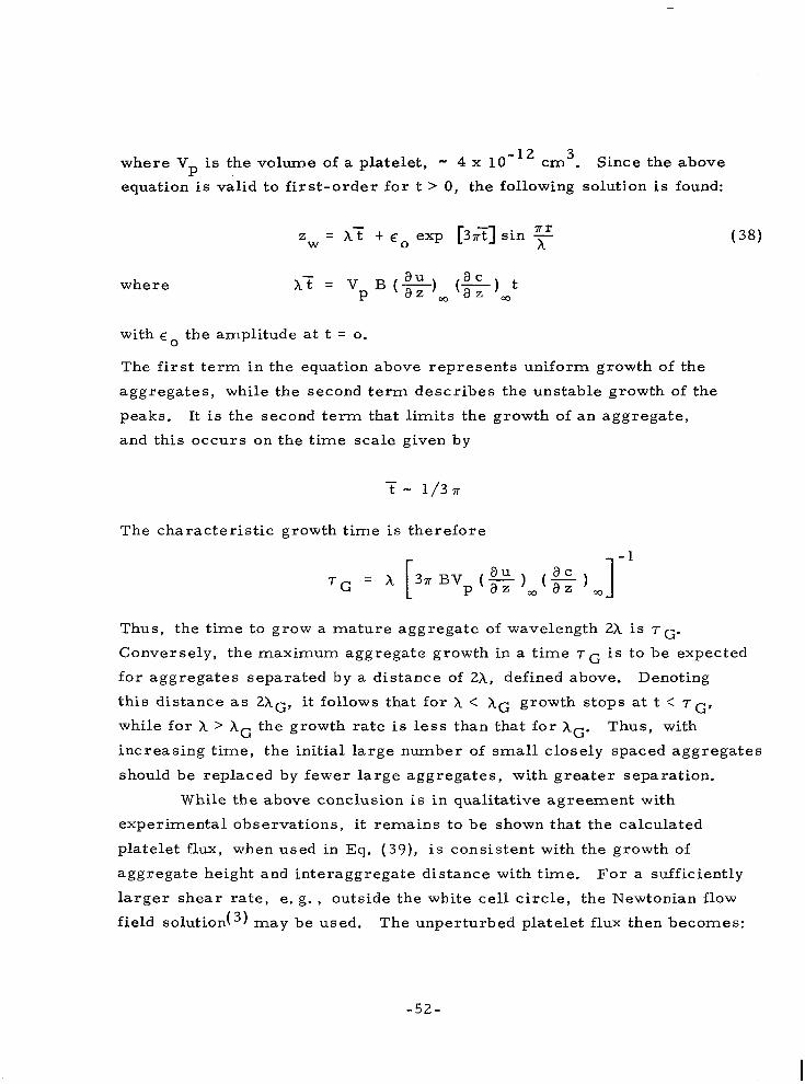
where V is the volume of a platelet, - 4 x crn3. Since the above
equation is val id to f i rs t -order for t > 0, the following soluti.on is found: P
where
with g o the amplitude at t = 0.
The f i rs t term in the equation above represents uniform growth of the
aggregates, while the second term describes the unstable growth of the
peaks. It is the second term that limits the growth of an aggregate,
and this occurs on the time scale given by
The characterist ic growth time is therefore
Thus, the time to grow a mature aggregate of wavelength 2X is T ~ .
Conversely, the maximum aggregate growth in a time T~ is to be expected
for aggregates separated by a distance of 2A, defined above. Denoting
this distance a s ZAG, it follows that for X < XG growth stops at t : T ~ ,
while for X > X G the growth rate is less than that for XG. Thus, with
increasing time, the initial large number of small closely spaced aggregates
should be replaced by fewer large aggregates, with greater separation.
While the above conclusion is in qualitative agreement with
experimental observations, it remains to be shown that the calculated
platelet flux, when used in Eq. (39), is consistent with the growth of
aggregate height and interaggregate distance with time. F o r a sufficiently
l a rge r shea r rate, e. g. , outside the white cell circle, the Newtonian flow
field solution(3) may be used. The unperturbed platelet flux then becomes:
-52-
I

I
Taking coo = 4. 6 x 10 8 platelets/cm3, the flux at A = 9 sec - l , ri = 0. 9 mm is 8 x 10⁴ platelets/cm2 - sec ard the expected interaggregate distance is
2XG w . 05 TG(microns) (41 1
To compare this calculation with experimental data, the
distribution of interaggregate distances (taking all adjacent aggregate
pairs) was measured at three t imes in a thrombus formed at the above
conditions. This data is presented in Fig. 21, with a "best f i t " curve
drawn through each set. The interval of 2X with the maximum number of aggregates is taken as the characterist ic interaggregate distance, and
is compared with 2XG in Fig. 25. The data a re seen to be in remarkable
agreement with the theoretical result, particularly in view of the many
approximations involved in the analysis. It should also be noted that there appears to be, as expected, a slight dependence of 2X on radial and
angular location in the thrombus. The latter effect is demonstrated by the
double-peaked distribution in Fig. 21 which reflects the Itage" of
aggregates along the azimuthally growing edges of the thrombus.
Two additional observations strengthen the model of aggregate growth described. First, the other possible growth mechanism, that of
direct interception of platelets by aggregates, yields a growth rate that is an order-of-magnitude smaller than the diffusion rate. Second, the
ability of platelet aggregates to trap red cells in their valleys depends on development of low velocity, low shear regions that are approximately an order-of-magnitude larger than the red cell diameter ( 8 ~ ) . Since red
cell trapping (and reverse flow in some cases) is observed, and at times
when both calculated and measured to be in the - 5 0 ~ range, there is little doubt that the aggregate and its surrounding flow field behave in the manner described.
-53-

A
l -
I -
l -
1 -
> a O L
0
T H E O R E T I C A L C H A R A C T E R I S T I C / GROWTH TIME
/
= 9 SEC"
= 0.9 MM
5 IO 15 20 -
25 C2531 TIME, MINUTES
Fig. 25 Interaggregate distance as a function of time.
- 54-
In s u m m a r y , it appears that platelet aggregates grow by an unstable
diffusion/surface shape interaction, interaggregate distances scale with
the local platelet f l u x rate and time, and the growth pattern is responsible for red cell trapping. Further investigations should consider the effects
of three-dimensional aggregate arrays, more general growth patterns, and specific platelet aggregation mechanisms.
-55-

VU. CONCLUDING DISCUSSION
The experimental data we have shown for the shape, size and growth rate of a thrombus on a foreign surface clearly show the effects of the flow of the blood on thrombus growth. Our understanding of the
physical processes affecting the evolution of a thrombus, though hindered
by the lack of knowledge of the detailed chemistry, has been increased by the application of simple fluid mechanical and mass transfer models.
The basic concept underlying the growth model is the existence of a balance between the rate at which an activating species diffuses and i s
convected from the thrombus and the rate at which new platelets can
diffuse from the flowing blood to the surface. The flow dependence of this platelet diffusion rate is emphasized as the growth rate limiting factor,
and the diffusion and convection of an activating species is shown to control the shape.
The asymptotic character of the thrombus growth is treated and succeeds in demonstrating the flow dependence of the size and spacing of aggregates, as well as their role in trapping the larger red cells. Though
the effect of the type of surface mater ia l i s not considered, we note the
role of a surface inhomogeneity in triggering the initial platelet aggregation leading to the thrombus. The platelet aggregation is shown to have an
unstable "switch-on" nature which occurs when the critical concentration
of activating species is exceeded. It seems that a smooth artificial
surface sufficiently free of surface imperfections may be quite non-
thrombogenic under some flow conditions even if it does not prevent clot formation of stagnant blood. To settle questions of this type, further experimentation and mathematical modeling is certainly needed.
Acknowledgment
The authors gratefully acknowledge the contributions and suggestions of P. Madras and the assistance of R. DeRocher, Jr. in the laboratory.
- 57-


REFERENCES
1. Monsler, M., Morton, W., and Weiss, R., "The Fluid Mechanics of Thrombus Formation' ' presented at the 3rd AIAA Fluid and Plasma Dynamics Conference, Los Angeles, Calif., June 1970, ALAA Paper NO. 70-787.
2. Madras, P. N. , Morton, W. , and Petschek, H., "The Dynamics of Thrombus Formation" presented at the Conference on Boundary Effects on Moving Blood, San Diego, Calif. , 13-1 5 January 1971, to be published in Federation Proceedings. Also Avco Everett Research Laboratory Research Report 365.
3. Petschek, H. E. and Weiss, R. F., "Hydrodynamic Problems in Blood Coagulation, ( I presented at the ALAA 8th Aerospace Sciences Meeting, New York, New York, January 1970, AIAA Paper No. 70-143.
4. Petschek, H. E., Adamis, D. and Kantrowitz, A., "An Ekperimental Preparation for the Study of Thrombus on Artificial Surfaces under Controlled Flow Conditions, Avco Everett Research Laboratory Research Report 314 (September 1968).
5. Petschek. H. , Adamis. D., and Kantrowitz, A. R. , "Stap;nation Flow
6. Petschek, H. E. and Madras, P. N., "Thrombus Formation on Artificial Surfaces, ' I in Proceedings of the National Heart Institute Artificial Heart Program Conference (June 1969).
7. Friedman, L. I., Liem, H., Grabowski, E. F., Leonard, E. F., and McCord, C. W. , "Inconsequentiality of Surface Properties for Init ial Platelet Adhesion, I' to be published in Trans. Amer. SOC. Ar t i f . Int. Organs, 1970.
8. French, J. E., "The Fine Structure of Experimental Thrombi, Thrombosis, ed. by S. Sherry, K. M. Brinkhous, E. Genton, and J. M. Stengle, pp. 300-321, National Academy of Sciences, Washington, D. C. (1969).
9. Obrien, J. R., "The Properties of the Platelet Membrane, I! Dynamics of Thrombus Formation and Dissolution, ed. by S. A. Johnson, and M. M. Guest, pp. 121-148, Lippincott, Philadelphia (19 69).
-59 -

10. Sher ry S. , B rinkhous, K. M. , Genton, E. , Stengle, J. M. , ed. Thrombosis, National Academy of Sciences, Washington, D. C. (1969).
11.
12.
13.
14.
15.
1 6.
17.
18.
Zucker, M, B., "Platelet Aggregation and Release Reactions Induced by Adenosine Diphosphate and Other Physiologic Substances, Thrombosis, ed. by Sherry, S., Brinkhous, K.M., Genton, E., and Stengle, J. M. , pp. 300-321, National Academy of Sciences, Washington, D. C. (1969).
Johnson, S. A. and Guest, M. M. ,, ed. Dynamics of Thrombus Formation and Dissolution, Lippincott, Philadelphia (19 69).
Marcus, A. J. and Zucker, M. B., The Physiology of Blood Platelets, Grune & Stratten Inc., New York (1965).
Kowalski, E. and Niewiarowski, S., ed. Biochemistry of Blood Platelets, Academic Press, New York (1967).
Johnson S. A,, Monts, R. W . , Rebuck, J. W. , and Horn, Ri C. , Ja; , Blood Platelets, Henry Ford Hospital International Symposium, Little, Brown & Company, Boston, Massachusetts (1961).
Schlichting, H., Boundary Layer Theory, 4th ed. , pp. 81-83, McGraw-Hill, New York (1960).
Merr i l l , E. W., Margetts, W. G. , Cokelet, G. R., and Gilliland, E. R. , "The Casson Equation and Rheology of Blood Near Zero Shear, Symposium on Biorheology, Proceedings of 4th International Congress on Rheology, ed. by A. Copley, pp. 135-143, Interscience, New York City (1965).
Rahn, A. W. , Tien, C. and Cerny, L. C., "Flow Properties of Blood Under Low Shear Rate, I t Chemical Engineering in Medicine and Biology, ed. by D. Hershey, pp. 45-83, Plenum Press, New York City (1967).
19. Bugliarello, G., Kapur, C. and Hsias, G., "The Profile Viscosity and Other Characteristics of Blood Flow in a Non-uniform Shear Field, I ' Symposium on Biorheology, Proceedings of 4th International Congress on Rheology, ed. b y A. Copley, pp. 351-370, Interscience, New York City (1965).
20. Kim, K. H. and Erasian, A. H. , "Non-Newtonian Stagnation Flow with Mass Injection, ' I Journal of Hydronautics, Vol. 2, No. 4 (October 1968).
21. Collingham, R. E., "Mass Transfer in Flowing Suspensions, Ph. D. Thesis, University of Minnesota, University Microfilms, Inc. (1968).
-6 0-
22. Merr i l l , E. W. , Margetts, W. G., Cokelet, G. R., and Gilliland, E. R., "The Casson Equation and Rheology of Blood Near Zero Shear, Symposium on Biorheology, Proceedings of 4th International Congress on Rheology, ed. by A. Copley, pp. 135-143, Interscience, New York City (1965).
23. Vand, V. , J. Phys. Colloid Chem. , Vol. 52, p. 277 (1948), in Ref. 4, p. 150; also, see Rubinow, S. I. and Keller, J. B., The' Transverse Force on a Spinning Sphere Moving In a Viscous Fluid, Journal of Fluid Mechanics, Vol. 11, Part 3, p. 447-459 (1961 j.
NASA-Langley, 1971 - 4 -6 1-