Embed Size (px)
Citation preview

© b
y D
oka
Gm
bH, A
-330
0 Am
stet
ten
999803102 12/2017en-GB
-
The Formwork Experts.
Edge protection system XPUser InformationInstructions for assembly and use (Method statement)© by Doka GmbH, A-3300 Amstetten
9803
1-25
6-01

2 999803102 - 12/2017
User Information Edge protection system XP

User Information Edge protection system XP
3999803102 - 12/2017
Contents
4 Introduction4 Elementary safety warnings8 System description
9 Edge protection on the structure – railing-height up to 1.20 m
10 Mounting the Handrail post XP 1.20m22 Mounting the safety barriers28 Structural design
33 Edge protection on the structure – railing-height up to 1.80 m
34 Mounting the Handrail post XP36 Mounting the safety barriers38 Structural design
40 Edge protection on the formwork41 General notes on structural design42 Framax adapter XP43 Frami adapter XP44 Timber-beam formwork adapter XP45 Bracket adapter XP FRR 50/3046 Railing clamp XP 40cm50 Insertion adapter XP51 Dokamatic adapter XP54 Dokadek handrail-post shoes56 Overview of safety-barrier heights with slab
formwork
57 Additional areas of use57 Safety barriers on parapets58 Fixing to steel components59 Safety barriers on sheeting walls60 Used with Doka floor end-shutter clamp61 Demarcation of work-zones
62 General remarks62 Individual design options63 Transporting, stacking and storing64 Doka multi-trip packaging
68 Component overview

4 999803102 - 12/2017
Introduction User Information Edge protection system XP
IntroductionElementary safety warnings
User target groups
▪ This booklet is aimed at all persons who will be work-ing with the Doka product or system that it describes. It contains information on the standard design for setting up this system, and on correct, compliant uti-lisation of the system.
▪ All persons working with the product described herein must be familiar with the contents of this booklet and with all the safety instructions it contains.
▪ Persons who are incapable of reading and under-standing this booklet, or who can do so only with dif-ficulty, must be instructed and trained by the cus-tomer.
▪ The customer is to ensure that the information mate-rials provided by Doka (e.g. User Information book-lets, Instructions for Assembly and Use, Operating Instruction manuals, plans etc.) are up to date and available to all users, and that they have been made aware of them and have easy access to them at the usage location.
▪ In the relevant technical documentation and form-work utilisation plans, Doka shows the workplace safety precautions that are necessary in order to use the Doka products safely in the usage situations shown. In all cases, users are obliged to ensure compliance with national laws, standards and regulations throughout the entire project and to take appropriate additional or alternative workplace safety precau-tions where necessary.
Hazard assessment
▪ The customer is responsible for drawing up, docu-menting, implementing and continually updating a hazard assessment at every job-site. This booklet serves as the basis for the site-specific hazard assessment, and for the instructions given to users on how to prepare and utilise the system. It does not substitute for these, however.
Remarks on this booklet
▪ This booklet can also be used as a generic method statement or incorporated with a site-specific method statement.
▪ Many of the illustrations in this booklet show the situation during formwork assembly and are therefore not always complete from the safety point of view.Any safety accessories not shown in these illustra-tions must still be used by the customer, in accord-ance with the applicable rules and regulations.
▪ Further safety instructions, especially warnings, will be found in the individual sections of this booklet!
Planning
▪ Provide safe workplaces for those using the form-work (e.g. for when it is being erected/dismantled, modified or repositioned etc). It must be possible to get to and from these workplaces via safe access routes!
▪ If you are considering any deviation from the details and instructions given in this booklet, or any application which goes beyond those described in the booklet, then revised static cal-culations must be produced for checking, as well as supplementary assembly instructions.
Regulations; industrial safety
▪ All laws, Standards, industrial safety regulations and other safety rules applying to the utilisation of our products in the country and/or region in which you are operating must be observed at all times.
▪ If a person or object falls against, or into, the side-guard component and/or any of its accessories, the component affected may only continue in use after it has been inspected and passed by an expert.
User Information Edge protection system XP Introduction
5999803102 - 12/2017
Rules applying during all phases of the assignment
▪ The customer must ensure that this product is erected and dismantled, reset and generally used for its intended purpose in accordance with the applica-ble laws, standards and rules, under the direction and supervision of suitably skilled persons. These persons' mental and physical capacity must not in any way be impaired by alcohol, medicines or drugs.
▪ Doka products are technical working appliances which are intended for industrial / commercial use only, always in accordance with the respective Doka User Information booklets or other technical docu-mentation authored by Doka.
▪ The stability and load-bearing capacity of all compo-nents and units must be ensured during all phases of the construction work!
▪ Do not step on or apply strain to cantilevers, clo-sures, etc. until suitable measures to ensure their stability have been correctly implemented (e.g. by tie-backs).
▪ Strict attention to and compliance with the functional instructions, safety instructions and load specifica-tions are required. Non-compliance can cause acci-dents and severe injury (risk of fatality) and consid-erable damage to property.
▪ Sources of fire in the vicinity of the formwork are pro-hibited. Heating appliances are only allowed if prop-erly and expertly used, and set up a safe distance away from the formwork.
▪ The customer must consider all types of weather conditions on equipment and in connection with the use or storage of the equipment (e.g. slippery sur-faces, risk of slippage, effects of wind, etc.) and must take steps in good time to safeguard the equipment and the surrounding areas and to protect the work-ers.
▪ All connections must be checked at regular intervals to ensure that they are secure and in full working order. In particular threaded connections and wedged con-nections have to be checked and retightened as nec-essary in accordance with activity on the jobsite and especially after out-of-the-ordinary occurrences (e.g. after a storm).
▪ It is strictly forbidden to weld Doka products – in par-ticular anchoring/tying components, suspension components, connector components and castings etc. – or otherwise subject them to heating.Welding causes serious change in the microstruc-ture of the materials from which these components are made. This leads to a dramatic drop in the failure load, representing a very great risk to safety.It is permissible to cut tie rods to length with metal cutting discs (introduction of heat at the end of the rod only), but it is important to ensure that flying sparks do not heat and thus damage other tie rods.The only articles which are allowed to be welded are those for which the Doka literature expressly points out that welding is permitted.
Assembly
▪ The equipment/system must be inspected by the customer before use, to ensure that it is in suitable condition. Steps must be taken to rule out the use of any components that are damaged, deformed, or weakened due to wear, corrosion or rot.
▪ Combining our formwork systems with those of other manufacturers could be dangerous, risking damage to both health and property. If you intend to combine different systems, please contact Doka for advice first.
▪ The equipment/system must be assembled and erected in accordance with the applicable laws, Standards and rules by suitably skilled personnel of the customer's, having regard to any and all required safety inspections.
▪ It is not permitted to modify Doka products; any such modifications constitute a safety risk.
Closing the formwork
▪ Doka products and systems must be set up so that all loads acting upon them are safely transferred!
Pouring
▪ Do not exceed the permitted fresh-concrete pres-sures. Over-high pouring rates overload the form-work, cause greater deflection and risk breakage.
Stripping out the formwork
▪ Do not strip out the formwork until the concrete has reached sufficient strength and the person in charge has given the order for the formwork to be stripped out!
▪ When stripping out the formwork, never use the crane to break concrete cohesion. Use suitable tools such as timber wedges, special pry-bars or system features such as Framax stripping corners.
▪ When stripping out the formwork, do not endanger the stability of any part of the structure, or of any scaffolding, platforms or formwork that is still in place!

6 999803102 - 12/2017
Introduction User Information Edge protection system XP
Transporting, stacking and storing
▪ Observe all country-specific regulations applying to the handling of formwork and scaffolding. For system formwork the Doka slinging means stated in this booklet must be used - this is a mandatory require-ment.If the type of sling is not specified in this booklet, the customer must use slinging means that are suitable for the application envisaged and that comply with the regulations.
▪ Remove any loose parts or fix them in place so that they cannot be dislodged or fall free!
▪ All components must be stored safely, following all the special Doka instructions given in the relevant sections of this booklet!
Maintenance
▪ Only original Doka components may be used as spare parts. Repairs may only be carried out by the manufacturer or authorised facilities.
Miscellaneous
The weights as stated are averages for new material; actual weights can differ, depending on material toler-ances. Dirt accretions, moisture saturation, etc. can also affect weight.We reserve the right to make alterations in the interests of technical progress.
Symbols used
The following symbols are used in this booklet:
DANGERIndicates a hazardous situation which, if not avoided, will result in death or serious injury.
WARNINGIndicates a hazardous situation which, if not avoided, could result in death or serious injury.
CAUTIONIndicates a hazardous situation which, if not avoided, could result in minor or moderate injury.
NOTICEIs used to address practices not related to physical injury.
InstructionIndicates that actions need to be taken by the user.
Sight-checkIndicates that you need to do a sight-check to make sure that necessary actions have been carried out.
TipPoints out useful practical tips.
ReferenceRefers to other documents and materials.

User Information Edge protection system XP Introduction
7999803102 - 12/2017

8 999803102 - 12/2017
Introduction User Information Edge protection system XP
System descriptionThis system is the universal safety solution for all edge protection needs. It fits in ideally with Doka systems – be they wall or floor formwork – for safeguarding slab edges or as guardrail systems on the structure shell.
All-in-one system for fall protection
on both formwork and structure shellVersatile ▪ with one single post for all the different kinds of side
protection ▪ for formwork, stairways and structure edges ▪ thanks to its different connectors covering all appli-
cations
Installation is quick and easy
because the easy-click function improves produc-tivityErgonomically engineered ▪ with a logical set-up procedure that makes the sys-
tem quick and self-explanatory to use ▪ for easy handling ▪ thanks to sturdy lightweight construction ▪ with captively integrated parts, which also cuts costs
Revolutionary bottom-fixed height extenders for the uprights
for grating heights of up to 1.80 m, with 20 % fewer uprights.This ingenious system ▪ provides full safety up to 1.20 m, with only one
upright ▪ can be extended to 1.80 m simply by adding a spe-
cially developed bottom-fixed height extender for the upright
▪ covers all applications perfectly with just two types of upright, obviating the need to keep many different types available on-site
Tested safety
Buy or rentRent it to get experience with it, and purchase as needed ▪ Hot-dip galvanised and extremely strong ▪ conforms to EN 13374 Class A ▪ Detailed User Information booklets ▪ Dimensioning diagrams incl. wind-loads
Handrail post XP in detail
▪ 1 type of upright for all types of safety barrier:- Protective grating XP- Guardrail boards- Scaffold tubes- Gap-free boarding
▪ "Easy-Click function":- makes it quick and easy to mount and dismount
the Handrail post XP 1.20m, with no tools needed
- locks automatically to prevent accidental lift-out
▪ Optional Toeboard holder XP:- for fixing a toeboard to safety barriers that use
guardrail boards or scaffold tubes- the Toeboard holder XP can be mounted and
dismounted quickly and easily, with no tools needed
▪ Handrail posts XP available in 3 heights:- 1.80m- 1.20m- 0.60m
Handrail post XP in detail
▪ Galvanised hollow frame for more stability and long lifespan.
▪ Toeboard and handles for safety and versatility. ▪ Stacking stirrups prevent the Protective gratings XP
from slipping.
Available formats:Width
Height 2.70m 2.50m 2.00m 1.20m1.20m ✓ ✓ ✓ ✓0.60m ✓ ✓ ✓ —
9803
1-20
8-02
9803
1-20
3-02

User Information Edge protection system XP Edge protection on the structure – railing-height up to 1.20 m
9999803102 - 12/2017
Edge protection on the structure – railing-height up to 1.20 mSa
fety
bar
riers
Protective grating XP Guardrail boards Scaffold tubes Gap-free boarding
Railing-height: 114 cmRailing-height: 119 cm (with 15 cm wide guardrail boards) Railing-height: 110 cm
Railing-height: 119 cm (with 15 cm wide guardrail boards)
Handrail post XP 1.20m
Fixi
ng d
evic
es
Railing clamp XP 40cm
Railing clamp XP 85cm
Screw-on shoe XP
Handrail-post shoe XP
Balcony adapter XP
Floor end-shut-ter profile XP Step bracket XP Bridge-deck
clamp XP
Area
s of
use
▪ Clamping range: 2 - 43 cm
▪ Fastened to end-face of concrete floor-slabs
▪ Fastened to concrete par-apets
▪ Clamping range: 2 - 85 cm
▪ Fastened to end-face of e.g. cantile-vered para-pets on bridges
▪ Floor-mounted on concrete floor-slabs
▪ Floor-mounted on concrete floor-slabs
▪ End-face attachment for balconies
▪ Attachment to the wall for slab top-ends
▪ End-face attachment for stairways
▪ Fastened to end-face of concrete floor-slabs
▪ Clamping range: 12 - 35 cm
▪ Fastened to end-face in reinforce-ment hoops, e.g. on bridge super-structures
Anch
orag
es
▪ in a Screw sleeve 20.0
▪ in an Attach-able sleeve 24mm
▪ in a hole sub-sequently drilled in the concrete
▪ using Doka express anchor 16x125mm
▪ with an alter-native anchor-bolt
▪ with Bridge edge beam anchor 15.0
▪ with Tie rod 15.0 and Super plate 15.0
▪ with Bridge edge beam anchor 15.0
▪ using Doka express anchor 16x125mm
▪ with an alter-native anchor-bolt
98031-200-01
98031-201-0198031-202-01
98031-220-02

10 999803102 - 12/2017
Edge protection on the structure – railing-height up to 1.20 m User Information Edge protection system XP
Mounting the Handrail post XP 1.20m
with Railing clamp XP 40cm
➤To adjust the clamping range of the Railing clamp XP 40cm, first take the wedge out of the wedge-slot.
➤Push the Railing clamp XP 40cm onto the floor-slab until it is pressed against the end face of the slab.
➤Hammer in the wedge until the hammer rebounds.
➤Working from below, push the Toeboard holder XP 1.20m onto the Handrail post XP 1.20m (not needed when using the Protective grating XP).
➤Push on the Handrail post XP 1.20m until it locks ("Easy-Click" function).
➤Mount the safety barriers (see the section headed "Mounting the safety barriers").
with Railing clamp XP 85cm
➤The procedure for mounting the Handrail post XP 1.20m with the Railing clamp XP 85cm is the same as with the Railing clamp XP 40cm.
Practical example
NOTICE ▪ If no fall protection (such as a facade scaf-
fold or platform) is in place when the side-guards are being mounted or dismounted, a personal fall-arrest system (PFAS) must be used (e.g. Doka personal fall-arrest set).
▪ Suitable anchorage points must be defined by a skilled person appointed by the con-tractor.
▪ Only fix the connectors to components that can reliably transfer the forces involved.
▪ The permitted. influence widths of the Handrail post XP and the permitted loads on the anchorages are given in the section headed "Structural design".
A Railing clamp XP 40cm
B Toeboard holder XP 1.20mC Handrail post XP 1.20m
The bracket of the toeboard holder must be pointing downward, facing the inside of the building.
98031-203-01
A
9803
1-20
3-02
B
C
A Railing clamp XP 40cmC Handrail post XP 1.20mD Locking mechanism
▪ The locking mechanism must engage. ▪ The handrail-post plates must be facing
towards the inside of the building.
A Railing clamp XP 85cmB Handrail post XP 1.20m
98031-203-03
AC
D
98031-236-01
A
B

User Information Edge protection system XP Edge protection on the structure – railing-height up to 1.20 m
11999803102 - 12/2017
with Screw-on shoe XP
3 fixing options: ▪ in a "Screw sleeve 20.0" ▪ in an "Attachable sleeve 24mm" ▪ in a hole subsequently drilled in the concrete
Fixed in a "Screw sleeve 20.0"
➤Push the Screw sleeve 20.0 into the freshly poured concrete.
a ... distance from edge min. 10 cmb ... 19.4 cm
➤After a concrete strength of B10 has been reached (characteristic cube compressive strength fck cube≥ 10 N/mm2): Punch through the cap of the Screw sleeve 20.0 with the threaded rod of the Screw-on shoe XP.
➤Push in the Screw-on shoe XP as far as the start of the thread in the screw-sleeve, then give it approx. 3 complete turns (i.e. until fully engaged) to secure it against being lifted out.
➤Working from below, push the Toeboard holder XP 1.20m onto the Handrail post XP 1.20m (not needed when using the Protective grating XP).
➤Push on the Handrail post XP 1.20m until it locks ("Easy-Click" function).
➤Mount the safety barriers (see the section headed "Mounting the safety barriers").
E Screw sleeve 20.0
F Screw-on shoe XP
The handrail-post holder must be facing towards the inside of the building.
98031-204-01
aE
b
98031-204-02
F
B Toeboard holder XP 1.20mC Handrail post XP 1.20m
The bracket of the toeboard holder must be pointing downward, facing the inside of the building.
C Handrail post XP 1.20mD Locking mechanismF Screw-on shoe XP
▪ The locking mechanism must engage. ▪ The handrail-post plates must be facing
towards the inside of the building.
9803
1-20
3-02
B
C
98031-204-03
F
C
D

12 999803102 - 12/2017
Edge protection on the structure – railing-height up to 1.20 m User Information Edge protection system XP
Fixed in an "Attachable sleeve 24mm"
➤Push the Attachable sleeve 24mm into the freshly poured concrete.
a ... distance from edge min. 10 cmb ... 16.5 cm
➤After a concrete strength of B10 has been reached (characteristic cube compressive strength fck cube≥ 10 N/mm2): Remove the plug from the Attachable sleeve 24mm and push in the Screw-on shoe XP 1.20m until it is fully engaged.
➤From now on, all the other steps are the same as with the Screw sleeve 20.0.
Fixed in a hole subsequently drilled in the concrete
➤Drill the hole, and clean it out.
a ... distance from edge min. 10 cmb ... Depth of drilled hole min. 16 cmc ... Diameter of drilled hole 24 mm➤Push the Screw-on shoe XP into the drilled hole until
it fully engages.
➤From now on, all the other steps are the same as with the Screw sleeve 20.0.
G Attachable sleeve 24mm
F Screw-on shoe XP
The handrail-post holder must be facing towards the inside of the building.
NOTICEAdditional precautions needed where stricter requirements are made regarding lift-out pro-tection for the safety barrier than in DIN EN 13374: ▪ Provide additional fixing to both the outside
Screw-on shoes XP of the safety barrier unit (e.g. by gluing in the Screw-on shoes XP with polyurethane foam).
▪ Alternatively, use Screw sleeves 20.0 for the outside Screw-on shoes XP instead of the Attachable sleeves 24mm.
98031-205-01
a
Gb
98031-205-02
F
F Screw-on shoe XP
The handrail-post holder must be facing towards the inside of the building.
NOTICEAdditional precautions needed where stricter requirements are made regarding lift-out pro-tection for the safety barrier than in DIN EN 13374: ▪ Provide additional fixing to both the outside
Screw-on shoes XP of the safety barrier unit (e.g. by gluing in the Screw-on shoes XP with polyurethane foam).
▪ Alternatively, use Screw sleeves 20.0 for the outside Screw-on shoes XP instead of the Attachable sleeves 24mm.
98031-206-01
a
b
c
98031-206-02
F
User Information Edge protection system XP Edge protection on the structure – railing-height up to 1.20 m
13999803102 - 12/2017
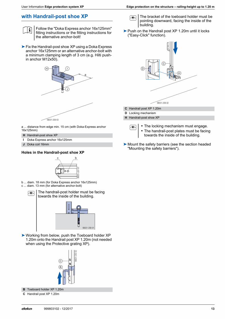
with Handrail-post shoe XP
➤Fix the Handrail-post shoe XP using a Doka Express anchor 16x125mm or an alternative anchor-bolt with a minimum clamping length of 3 cm (e.g. Hilti push-in anchor M12x50).
a ... distance from edge min. 15 cm (with Doka-Express anchor 16x125mm)
Holes in the Handrail-post shoe XP
b ... diam. 18 mm (for Doka Express anchor 16x125mm)c ... diam. 13 mm (for alternative anchor-bolt)
➤Working from below, push the Toeboard holder XP 1.20m onto the Handrail post XP 1.20m (not needed when using the Protective grating XP).
➤Push on the Handrail post XP 1.20m until it locks ("Easy-Click" function).
➤Mount the safety barriers (see the section headed "Mounting the safety barriers").
Follow the "Doka Express anchor 16x125mm" fitting instructions or the fitting instructions for the alternative anchor-bolt!
H Handrail-post shoe XPI Doka Express anchor 16x125mmJ Doka coil 16mm
The handrail-post holder must be facing towards the inside of the building.
B Toeboard holder XP 1.20mC Handrail post XP 1.20m
98031-208-03
a
H I
J
9803
1-20
7-01
bc
98031-208-01
9803
1-20
3-02
B
C
The bracket of the toeboard holder must be pointing downward, facing the inside of the building.
C Handrail post XP 1.20mD Locking mechanismH Handrail-post shoe XP
▪ The locking mechanism must engage. ▪ The handrail-post plates must be facing
towards the inside of the building.
98031-208-02
H
C
D

14 999803102 - 12/2017
Edge protection on the structure – railing-height up to 1.20 m User Information Edge protection system XP
Handrail-post shoe XP box-out
The retrievable Handrail-post shoe XP box-out is for forming a recess around handrail-post shoes if an extra layer of concrete (max. 5 cm thick) has to be subse-quently applied to the raw concrete slab.
➤Drill a suitable hole in the concrete floor-slab, and clean out the hole.
a ... distance from edge min. 15 cm➤Place the Handrail-post shoe XP box-out onto the
concrete (i.e. the drilled hole).➤Place a Handrail-post shoe XP into the box-out.➤Anchor in the concrete using a Doka express anchor
16x125mm or an alternative anchor-bolt.
➤ Insert a Handrail post XP and erect the safety bar-rier.
➤Apply the extra concrete layer.
➤After pouring, dismount the safety barrier and the Handrail post XP.
➤Undo the Doka express anchor 16x125mm and remove both the Handrail-post shoe XP and the box-out.
➤Fill out the recess in the concrete, flush with the sur-rounding surface.
NOTICE ▪ If no fall protection (such as a facade scaf-
fold or platform) is in place when this item is being mounted or dismounted, a personal fall-arrest system (PFAS) must be used (e.g. Doka personal fall-arrest set).
▪ Suitable anchorage points must be defined by a skilled person appointed by the con-tractor.
▪ Only fix the connectors to components that can reliably transfer the forces involved.
TR1010-200-02
A
a
TR1010-200-01
B
C
D
TR1010-201-01
E
F
A Drilled holeB Handrail-post shoe XP box-outC Handrail-post shoe XPD Doka express anchor 16x125mmE Handrail post XPF Concrete (max. 5 cm thick)
TR1010-202-01
B
C
D
TR1010-203-01
E
F

User Information Edge protection system XP Edge protection on the structure – railing-height up to 1.20 m
15999803102 - 12/2017
with Balcony adapter XP
Balcony adapter XP is for cordoning off at the slab edge on balconies. End-face attachment of the Balcony adapter XP to the balcony slab leaves space between the balcony and the protective grating so that the spe-cial cover angles commonly used for balconies can be installed. ▪ Slab thickness 16 cm or more (14 cm or more in the
case of prefabricated concrete members) ▪ Used with Protective grating XP, guardrail boards or
scaffold tubes ▪ Anchoring with Bridge edge beam anchor 15.0
Practical example
View from below
Please note: ▪ Minimum concrete strength required: B10 ▪ Minimum anchor distance from edge vertically: 8 cm ▪ Minimum anchor distance from edge, horizontally (at
the corner): 25 cm
Close-up:
a ... 8 cmb ... ≥ 8 cmc ... ≥ 16 cm
Note:When using pre-cast concrete members, dimension a can be reduced to 6 cm if necessary (slab thickness c 14 cm).
Assembly
➤Position the Bridge edge beam anchor 15.0 with the Nailing cone 15.0 on the stop-end formwork and embed them in the concrete.
➤Remove the Nailing cone 15.0 and screw the Tie rod 15.0 into the bridge edge beam anchor (0.50m).
➤Push the Balcony adapter XP onto the tie rod as far as the floor-slab and tighten it using the Wing nut 15.0.
a ... Space for mounting the cover angle: 8 cmb ... Space for mounting the cover angle: 5 cmc ... 14.4 cm
Note:Use timber on site to close the gap between the con-crete and the railing. The timber may only be removed when work is carried out on the cover angle.
A Balcony adapter XPB Handrail post XP 1.20mC e.g. Protective grating XP 2.70x1.20mD Floor-slab
A Balcony adapter XPB Handrail post XP 1.20m
A
TR1094-200-01
D
C
B
TR1094-206-01
c
ab
A
B
A Bridge edge beam anchor 15.0B Nailing cone 15.0C Formwork sheeting of the stop-end formwork
A Bridge edge beam anchor 15.0D Tie rod 15.0 0.5m
E Balcony adapter XPF Wing nut or Super plate 15.0X Cover angle for balcony
Make sure that the Balcony adapter XP is secure!
CA B
TR1094-201-01
A D
TR1094-202-01
TR1094-203-01E F
a
c
b
X

16 999803102 - 12/2017
Edge protection on the structure – railing-height up to 1.20 m User Information Edge protection system XP
➤Push on the Handrail post XP 1.20m until it locks ('Easy-Click' function).
Depending on barrier type, barrier height x is as fol-lows: ▪ Protective grating XP: 113 cm ▪ Scaffold tubes: 107 cm ▪ Guardrail boards 15 cm: 118 cm
E Balcony adapter XPG Handrail post XP 1.20m
▪ The locking mechanism must engage. ▪ The handrail-post plates must be facing
towards the inside of the building.
TR1094-204-01
E
G
TR1094-207-01
x

User Information Edge protection system XP Edge protection on the structure – railing-height up to 1.20 m
17999803102 - 12/2017
with Floor end-shutter profile XP
The Floor end-shutter profile XP is used for fast, safe forming of slab stop-ends. ▪ For slab thicknesses of up to 30 cm ▪ Slabs can be end-shuttered with either boards or
formwork sheeting.
Practical example
Assembly
➤Provide a suitable tie-hole in the concrete wall for a Tie rod 15.0.
a ... 15 cm
➤Place a 5 x 10 cm spacer board on the appropriate bracket of Floor end-shutter profile XP and secure it to the Floor end-shutter profile XP.
➤Mount the Floor end-shutter profile XP to the con-crete wall with a Tie rod 15.0 and 2 Super plates 15.0, but do not tighten these yet.
➤Place a 5 x 20 cm + 5 x 13 cm cm board (or a 5 x 33 cm board) onto the top bracket of the Floor end-shutter profile XP, and fix them onto the Floor end-shutter profile XP with screws.
A Floor end-shutter profile XPB Handrail post XP 1.20mC End-shuttering (5x20 cm board)D Slab stop-end (5x13 cm board)
NOTICE ▪ If no fall protection (such as a facade scaf-
fold or platform) is in place when this item is being mounted or dismounted, a personal fall-arrest system (PFAS) must be used (e.g. Doka personal fall-arrest set).
▪ Suitable anchorage points must be defined by a skilled person appointed by the con-tractor.
▪ Only fix the connectors to components that can reliably transfer the forces involved.
E Prepared or subsequently drilled tie-hole
A
TR1008-200-03
C
B
A
D
E
TR1008-201-02
a
A Floor end-shutter profile XPF Spacer board (5 x 10 cm)G Screw (site-provided) to fix the spacer board in positionH Super plate 15.0I Tie rod 15.0
The slabs can also be end-shuttered with (doubled-up) Doka formwork sheets 3-SO 21mm.
A Floor end-shutter profile XPG Screw (site-provided) to fix the spacer board in positionN 2 Doka formwork sheets 3-SO 21mm (33 cm high)O 2 Doka formwork sheets 3-SO 21mm (10 x 10 cm)
H
A
F
H
TR1008-201-01
I
G
A
N
TR1008-204-01
O
G
G

18 999803102 - 12/2017
Edge protection on the structure – railing-height up to 1.20 m User Information Edge protection system XP
➤Then pull the Floor end-shutter profile XP, with the boards mounted to it, tightly against the concrete wall.
Note:The Sealing tape KS at the slab stop-end (board 5 x 20 cm) is necessary and it prevents the escape of cement slurry (possible bending of the slab stop-end of max. 3 mm taken into account).
➤Push a Handrail post XP 1.20m onto the Floor end-shutter profile XP until it locks ('Easy-Click' function).
➤Hook in a Protective grating XP 2.70x1.20m.
Practical example with slab made of prefabricated concrete members, slab thickness 30 cm
b ... slab thickness max. 30 cm
A Floor end-shutter profile XPC Slab stop-end (5 x 20 cm board)D Slab stop-end (5 x 13 cm board)G Screw (site-provided) to fix the spacer board in positionZ Sealing tape KS 10x3mm 10m
A
D
C
TR1008-202-01
G
G
Z
TR1008-206-01
Z
C
A Floor end-shutter profile XPJ Handrail post XP 1.20mK Protective grating XP 2.70x1.20m
L Slab made of prefabricated concrete membersM Slab (cast-in-place concrete)
A
K
TR1008-200-01
J
TR1008-200-02
bL
M

User Information Edge protection system XP Edge protection on the structure – railing-height up to 1.20 m
19999803102 - 12/2017
Alternative anchoring methods
2 possibilities: ▪ The Floor end-shutter profile XP can also be fixed to
the wall with a Bridge edge beam anchor, tie rod and super plate (single-sided anchorage).
▪ Any other type of anchorage which ensures that the forces occurring are safely transferred.Follow the manufacturers' applicable fitting instruc-tions.
a ... 15 cmA Floor end-shutter profile XPH Super plate 15.0I Tie rod 15.0P Bridge edge beam anchor 15.0
Max. tensile force allowed to occur in the anchorage: 11 kN
A
P
TR1008-205-01
I
H
a

20 999803102 - 12/2017
Edge protection on the structure – railing-height up to 1.20 m User Information Edge protection system XP
with Step bracket XP
When the Step bracket XP is used, tiles or flagstones which project by up to 4 cm can be laid on the steps without making it necessary to remove the guard rails.Barrier with scaffold tubes or guardrail boards possible.
➤Fix the Step bracket XP using a Doka express anchor 16x125mm or an alternative anchor-bolt (M16 at max.) with a minimum clamping length of 3 cm (e.g. Hilti push-in anchor M12x50).
a ... distance from edge min. 15 cm (with Doka-Express anchor 16x125mm)
Holes in the Step bracket XP
b ... 18 mm (for Doka express anchor 16x125mm)c ... 14 mm (for alternative anchor-bolt)
➤Push on the Handrail post XP 1.20m until it locks ('Easy-Click' function).
➤Mount the safety barriers (see the section headed 'Mounting the safety barriers').
The Step bracket XP can also be used for hori-zontal barriers at the slab edge. In this case Protective grating XP can also be used.
Follow the 'Doka express anchor 16x125mm' fitting instructions or the fitting instructions for the alternative anchor-bolt!
NOTICEA board-smooth concrete surface is needed for anchoring the Step bracket XP.
Required minimum tightening torque of Doka express anchor 16x125mm: 120 Nm (corresponds to approx. 25 kg with a 50 cm extension)Tighten the bolted joints regularly (depending on the stresses to which they are subjected).
I Doka express anchor 16x125mmJ Doka coil 16mmK Step bracket XP
The handrail-post holder must be facing towards the outside of the stairway.
98031-210-04
Ia
a
J
K
9803
1-20
9-01
b
c
Easier fixing method:➤Pre-mount a Doka express anchor
16x125mm, fit the Step bracket XP onto it and tighten.
C Handrail post XP 1.20mD RetainerK Step bracket XP
▪ The locking mechanism must engage. ▪ The handrail-post plates must be facing
towards the inside of the building.
98031-210-03
K
C
D

User Information Edge protection system XP Edge protection on the structure – railing-height up to 1.20 m
21999803102 - 12/2017
with Bridge-deck clamp XP
➤To adjust the clamping range of the Bridge-deck clamp XP, first take the wedge out of the wedge-slot.
➤Hook both clamping plates of the Bridge-deck clamp XP into the reinforcement hoop, and wedge them in place firmly.
➤Hammer in the wedge until the hammer rebounds.
a ... clear gap between the reinforcement hoops min. 13 cm
Dimensions of the reinforcement hoop
b ... 12 cm - 35 cm c ... min. 12 cm d ... min. 1 cm
➤Working from below, push the Toeboard holder XP 1.20m onto the Handrail post XP 1.20m (not needed when using the Protective grating XP).
➤Push on the Handrail post XP 1.20m until it locks ("Easy-Click" function).
➤Mount the safety barriers (see the section headed "Mounting the safety barriers").
Raising the safety barrier
Note:Lifting and fixing the toeboard is only possible in com-bination with the Bridge-deck clamp XP.
➤Raise the toeboard and Toeboard holder XP.➤Fix the toeboard with a nail resting on the support
plate.
a ... 15 cm
The Bridge-deck clamp XP must be resting against the structure.
L Bridge-deck clamp XPM Reinforcement hoop
The handrail-post holder must be facing towards the inside of the building.
B Toeboard holder XP 1.20mC Handrail post XP 1.20m
98031-211-02
M
L
a
98031-211-01
b
c
d
9803
1-20
3-02
B
C
The bracket of the toeboard holder must be pointing downward, facing the inside of the building.
C Handrail post XP 1.20mD Locking mechanismL Bridge-deck clamp XP
▪ The locking mechanism must engage. ▪ The handrail-post plates must be facing
towards the inside of the building.
WARNINGBecause the Protective grating XP is now raised, objects can fall off the edge of the struc-ture.➤Take any loose items away from the edge.➤Only raise the grating very briefly, e.g. while
carrying out necessary work on the slab edge.
A ToeboardB Toeboard holder XPC NailD Support plate
98031-211-03
LC
D
98031-216-01
A
B A
D C
a
22 999803102 - 12/2017
Edge protection on the structure – railing-height up to 1.20 m User Information Edge protection system XP
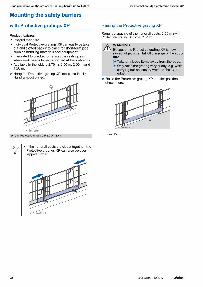
Mounting the safety barriers
with Protective gratings XP
Product features: ▪ Integral toeboard ▪ Individual Protective gratings XP can easily be taken
out and slotted back into place for short-term jobs such as handling materials and equipment.
▪ Integrated U-bracket for raising the grating, e.g. when work needs to be performed at the slab edge
▪ Available in the widths 2.70 m, 2.50 m, 2.00 m and 1.20 m.
➤Hang the Protective grating XP into place in all 4 Handrail-post plates.
Raising the Protective grating XP
Required spacing of the handrail posts: 2.50 m (with Protective grating XP 2.70x1.20m)
➤Raise the Protective grating XP into the position shown here.
a ... max. 15 cmA e.g. Protective grating XP 2.70x1.20m
▪ If the handrail posts are closer together, the Protective gratings XP can also be over-lapped further.
98031-200-01
A
98031-217-01
WARNINGBecause the Protective grating XP is now raised, objects can fall off the edge of the struc-ture.➤Take any loose items away from the edge.➤Only raise the grating very briefly, e.g. while
carrying out necessary work on the slab edge.
98031-215-01
a

User Information Edge protection system XP Edge protection on the structure – railing-height up to 1.20 m
23999803102 - 12/2017
Protective grating holder XP
The Protective grating holder XP is used to affix the Protective grating XP to walls with sufficient load-bear-ing strength, e.g. as fall protection for door openings, shafts and balconies. Protective grating XP 1.20x1.20m is eminently suitable for this.Depending on how they are installed, the Protective grating holders XP can be used to install protective gratings as quickly removable or semi-permanent guardrail systems.
WARNING➤The Protective grating holders XP must
always be installed in such a way that if load is applied, the Protective grating XP is sup-ported by the building's structure.
➤ Installation versions B, C and D permit quick temporary removal and the Protective grat-ing XP must be secured to the Protective grating holders XP with cable ties (holes pro-vided for the purpose) in such a way that the grating cannot be inadvertently opened or pushed aside.
➤ If Protective gratings XP are removed, use personal protective equipment as applicable to prevent falls, for example the Doka per-sonal fall-arrest set can be used for this pur-pose.
Version A Version BThe Protective grating XP can be secured semi-perma-nently to the masonry wall with the Protective grating holders XP.
The Protective grating XP can be lifted up and temporarily removed.
Close-up A Close-up B Close-up C Close-up DTR1050-200-01
B
A
B
A
A
TR1050-201-01
C
D
A
B
A
TR1050-200-03
A
B
TR1050-200-02
A
B
C
TR1050-201-03
A
B
TR1050-201-02
C
A
D
B

24 999803102 - 12/2017
Edge protection on the structure – railing-height up to 1.20 m User Information Edge protection system XP
Version C Version DThe Protective grating XP can be pushed aside and tem-porarily removed.
The Protective grating XP can be pushed aside (disen-gages after being moved approx. 2 cm, see Close-up I) and then swung inward (door function).
Close-up E Close-up F Close-up G Close-up H
Close-up I
A Protective grating holder XPB e.g. Protective grating XP 1.20x1.20mC Wall plugs and screws (diameter 6 mm) or bolt-firing tool (com-
ply with manufacturer's instructions and fitting instructions)D Cable tie
TR1050-202-01
B
E
F
A
A
TR1050-204-01
B
G
H
A
A
TR1050-202-03
A
B
TR1050-202-02
B
A
C
D
TR1050-204-03
A
B
TR1050-204-02
C
A
TR1050-204-04
A
B
A
1
2

User Information Edge protection system XP Edge protection on the structure – railing-height up to 1.20 m
25999803102 - 12/2017
with guard-rail boards
➤Place guard-rail boards on the handrail-post plates and secure them with nails (diam. 5 mm).
➤Raise the Toeboard holder XP, place the toeboard up against the Handrail post XP and lower the Toe-board holder XP onto it.
➤Secure the toeboard with nails (diam. 5 mm).
with Scaffold-tube holder D34mm/48mm
The Scaffold tube holder D34/48mm makes it possible to attach scaffold tubes to the Handrail post XP. ▪ Can be used for both D34mm and D48mm scaffold
tubes. ▪ Allows scaffold tubes to be fixed in the diagonal (e.g.
beside stairways). ▪ Fixes both scaffold tubes when tubes are arranged in
parallel.
➤Place the scaffold tubes into the handrail-post plates of the Handrail posts XP.
➤Turn the clamping plate of the scaffold-tube holder into the correct position (as shown by the punched direction-marks for the respective tube diameter).
➤Pass the scaffold-tube holder between the scaffold tubes and hang it into place at the back of the Hand-rail post XP.
➤Wedge the scaffold-tube holder firmly into place.
a ... min. excess length 10 cm➤Raise the Toeboard holder XP, place the toeboard
up against the Handrail post XP and lower the Toe-board holder XP onto it.
B Guard-rail boardsC Toeboard holder XPD Toeboard
NOTICE➤A scaffold-tube holder must be mounted as
an anti-liftout guard on every handrail-post plate.
➤Every scaffold tube must be fixed with the wedge of the scaffold-tube holder, to pre-vent it slipping sideways.
A Handrail post XP 1.20mB D34mm or D48mm scaffold tube
98031-201-01
B
D
C
98031-262-01
A
B
Position of the clamping plateon D34mm scaffold tubes on D48mm scaffold tubes
Note on D34mm scaffold tubes: ▪ If the clamping plate is rotated 180° (so that the 'heel' is pointing
upwards), the vertical position of the D34mm scaffolding tube can be changed by 14 mm. This makes it possible to obtain the 47 cm gap permitted in the vertical between the waist-level guardrail and the intermediate guardrail.
▪ The permitted influence widths must be specially dimensioned, as a function of the wall thickness and the strength of the mate-rial.
C Clamping plate of the Scaffold-tube holder D34/48mm
A Handrail post XP 1.20mB Scaffold tube D34mm or D48mmD Scaffold tube holder D34/48mm
98031-263-02C98031-263-01
C
98031-264-01
A
B
D
98031-261-03
a

26 999803102 - 12/2017
Edge protection on the structure – railing-height up to 1.20 m User Information Edge protection system XP
➤Secure the toeboard with nails (diam. 5 mm).
Practical examples
with Scaffold tube holder D48mm
➤Push the Scaffold tube holder D48mm onto the handrail post plate.
➤ Insert scaffold tubes through the Scaffold-tube hold-ers D48mm and wedge them in place firmly.
➤Raise the Toeboard holder XP, place the toeboard up against the Handrail post XP and lower the Toe-board holder XP onto it.
E Toeboard holder XPF Toeboard
Scaffold-tube arrangementScaffold tubes Straight Angled
D34mm
D48mm
98031-265-01
E
F
98031-259-01 98031-260-01
98031-257-01 98031-258-01
NOTICE➤A scaffold-tube holder must be mounted as
an anti-liftout guard on every handrail-post plate.
➤Every scaffold tube must be fixed with the wedge of the scaffold-tube holder, to pre-vent it slipping sideways.
E Scaffold tube holder D48mm
C Toeboard holder XPD ToeboardF Scaffold tube
98031-218-01
E
E
98031-218-02
F
F
C
D

User Information Edge protection system XP Edge protection on the structure – railing-height up to 1.20 m
27999803102 - 12/2017
➤Push a Scaffold tube holder D48mm onto the other end of each scaffold tube and fix it onto the handrail post plate.
➤ Insert the scaffold tubes for the next section through the Scaffold-tube holders D48mm and wedge them in place firmly.
➤Raise the Toeboard holder XP, place the toeboard up against the Handrail post XP and lower the Toe-board holder XP onto it.
➤From now on, repeat Steps 4 to 6 until you reach the end of the safety barrier.
➤At the end of the safety barrier, fix the scaffold tubes with the wedges of the Scaffold tube holders D48mm.
with gap-free boarding
Field-built solution using e.g. Doka formwork sheets.
E Scaffold tube holder D48mm
C Toeboard holder XPD ToeboardF Scaffold tube
98031-218-03
E E
98031-218-04
F
F
C
D
98031-220-01

28 999803102 - 12/2017
Edge protection on the structure – railing-height up to 1.20 m User Information Edge protection system XP
Structural design
General notes on structural design
a ... Span b ... Cantilever e ... Influence width
Note:The plank and board thicknesses given here comply with the C24 category to EN 338.Observe all national regulations applying to deck-boards and guard-rail boards.
Permitted cantilever (b) of edge-protection compo-nents
Railing clamp XP 40cm Railing clamp XP 85cm
Clamped to concrete
1) with toeboard 3 x 20 cm, 4 x 20 cm or 5 x 20 cm2) with toeboard 5 x 20 cm
NOTICEA fundamental distinction must be made between the span (a) and the influence width (e): ▪ The span is the distance between the hand-
rail-post uprights (posts). ▪ The permitted influence width of a handrail-
post upright is stated in the respective tables.
▪ The actual influence width can only be determined by calculation, and corresponds to roughly the spacing 'a' between the hand-rail-post uprights, and in the cantilever-arm zone to around b + a/2.
▪ The span (a) of the handrail-post uprights is roughly equal to the influence width (e) if
- they are evenly spaced- the guardrail boards are either continu-
ous or are jointed at the handrail posts, and
- there are no cantilevering projections ▪ The wind conditions likely to be encoun-
tered in Europe, in accordance with EN 13374, are largely recognised by the dynamic pressure q=0.6 kN/m2 (highlighted grey in the tables).
Edge-protection component
Permitted cantileverDynamic pressure q
[kN/m2]0.2 0.6 1.1 1.3
Protective grating XP 2.70x1.20m 0.6 m 0.6 m 0.4 m 0.1 mGuardrail board 2.5 x 12.5 cm 0.3 mGuardrail board 2.4 x 15 cm 0.5 mGuardrail board 3 x 15 cm 0.8 mGuardrail board 4 x 15 cm 1.4 mGuardrail board 3 x 20 cm 1.0 mGuardrail board 4 x 20 cm 1.6 mGuardrail board 5 x 20 cm 1.9 mScaffold tube 48.3mm 1.3 m
98031-222-01a a
e e e
b
NOTICEWhen gap-free boarding is used, 2 extra Handrail posts XP (A) must be mounted at the corners.
Dynamic pressure q
[kN/m2]
Permissible influence width 'e' [m]
Prot
ectiv
e gr
atin
g XP
2.
70x1
.20m
Guard-rail boards
Scaf
fold
tube
s 48
.3m
m 2)
Gap
-free
boa
rdin
g
2.5
x 12
.5
cm 1)
2.4
x 15
cm
3 x
15
cm
4 x
15
cm
3 x
20
cm
4 x
20
cm
5 x
20
cm
0.2
2.5
1.8 1.9 2.7 3.6 2.9 3.4 3.4 5.0 1.80.6 1.8 1.9 2.7 3.3 2.4 2.4 2.4 5.0 1.31.1 1.8 1.8 1.8 1.8 1.3 1.3 1.3 5.0 0.71.3 1.8 1.5 1.5 1.5 1.1 1.1 1.1 4.4 0.6
9803
1-22
3-01
A

User Information Edge protection system XP Edge protection on the structure – railing-height up to 1.20 m
29999803102 - 12/2017
Screw-on shoe XP
Anchored in B10 grade concrete
Distance of anchorage point from edge: min. 10 cm
1) with toeboard 3 x 20 cm, 4 x 20 cm or 5 x 20 cm2) with toeboard 5 x 20 cm
Handrail-post shoe XP
Anchored by Doka Express anchor 16x125mm in "green" (new) concrete
Distance of anchorage point from edge: min. 15 cm
1) with toeboard 3 x 20 cm, 4 x 20 cm or 5 x 20 cm2) with toeboard 5 x 20 cm
Anchored with an alternative anchor-bolt, e.g. Hilti push-in anchor M12x50, in C20/25 grade concrete
Distance of anchorage point from edge: min. 12 cm, in building-elements that are at least 15 cm thick
1) with toeboard 3 x 20 cm, 4 x 20 cm or 5 x 20 cm2) with toeboard 5 x 20 cm
Dynamic pressure q
[kN/m2]
Permissible influence width 'e' [m]
Prot
ectiv
e gr
atin
g XP
2.7
0x1.
20m Guardrail boards
Scaf
fold
tube
s 48
.3m
m 2)
Gap
-free
boa
rdin
g
2.5
x 12
.5
cm 1)
2.4
x 15
cm
3 x
15
cm
4 x
15
cm
3 x
20
cm
4 x
20
cm
5 x
20
cm
0.2
2.5
1.8 1.9 2.7 3.0 2.2 2.2 2.2 5.0 1.20.6 1.8 1.9 2.7 2.8 2.0 2.0 2.0 5.0 1.11.1 1.8 1.5 1.5 1.5 1.1 1.1 1.1 4.3 0.61.3 1.6 1.3 1.3 1.3 0.9 0.9 0.9 3.7 0.5
Characteristic cube compressive strength of the new concrete (fck,cube): ≥ 14 N/mm2
Dynamic pressure q
[kN/m2]
Permissible influence width 'e' [m]
Prot
ectiv
e gr
atin
g XP
2.
70x1
.20m
Guard-rail boards
Scaf
fold
tube
s 48
.3m
m 2)
Gap
-free
boa
rdin
g
2.5
x 12
.5
cm 1)
2.4
x 15
cm
3 x
15
cm
4 x
15
cm
3 x
20
cm
4 x
20
cm
5 x
20
cm
0.2
2.5
1.8 1.9 2.7 3.6 2.9 3.4 3.4 5.0 1.80.6 1.8 1.9 2.7 3.3 2.4 2.4 2.4 5.0 1.31.1 1.8 1.8 1.8 1.8 1.3 1.3 1.3 5.0 0.71.3 1.8 1.5 1.5 1.5 1.1 1.1 1.1 4.4 0.6
Actual tensile force in Express anchor: Ed= 13.6 kN (F = 9.1 kN)
Dynamic pressure q
[kN/m2]
Permissible influence width 'e' [m]
Prot
ectiv
e gr
atin
g XP
2
.70x
1.20
m
Guard-rail boardsSc
affo
ld tu
bes
48.3
mm
2)
Gap
-free
boa
rdin
g
2.5
x 12
.5
cm 1)
2.4
x 15
cm
3 x
15
cm
4 x
15
cm
3 x
20
cm
4 x
20
cm
5 x
20
cm
0.2
2.5
1.8 1.9 3.0 3.0 2.0 2.0 2.0 5.0 1.10.6 1.8 1.9 2.7 2.7 1.9 1.9 1.9 5.0 1.01.1 1.8 1.5 1.5 1.5 1.1 1.1 1.1 4.1 0.51.3 1.5 1.2 1.0 1.2 0.9 0.9 0.9 3.5 0.5
Required safe working load of alternative anchor-bolts: Rd≥ 9.9 kN (Fperm.≥ 6.6 kN)Follow the manufacturer's applicable fitting instruc-tions.
30 999803102 - 12/2017
Edge protection on the structure – railing-height up to 1.20 m User Information Edge protection system XP
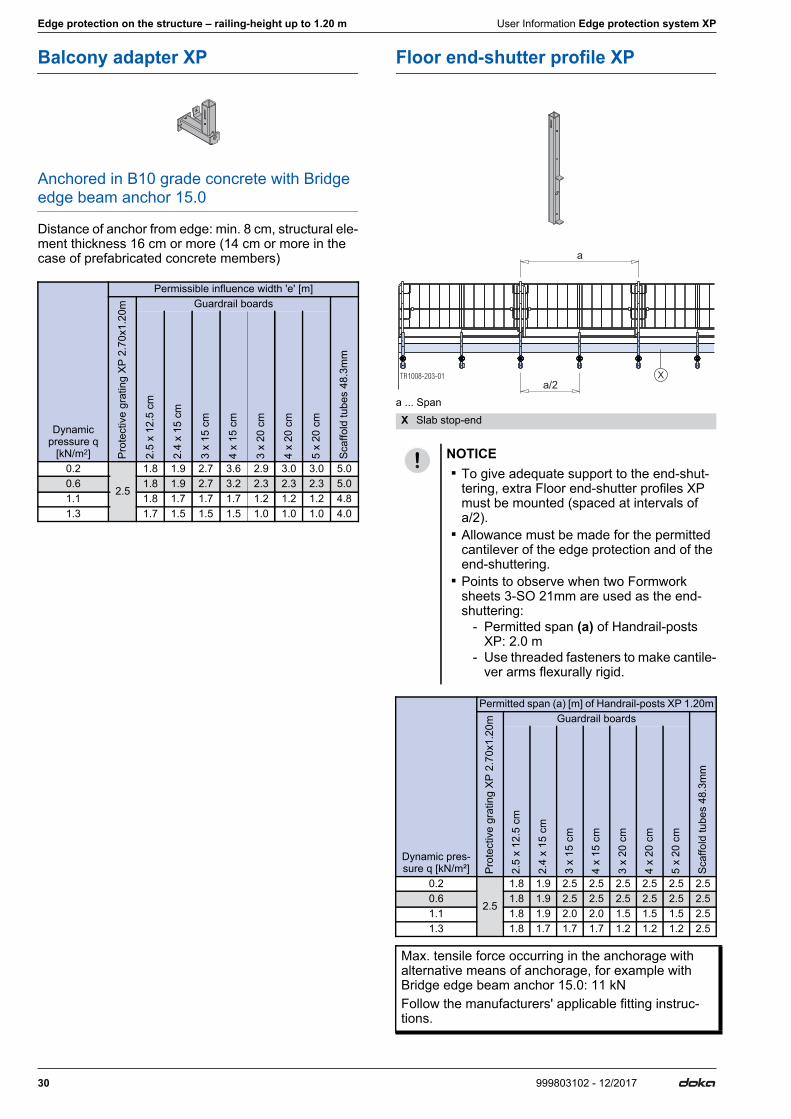
Balcony adapter XP
Anchored in B10 grade concrete with Bridge edge beam anchor 15.0
Distance of anchor from edge: min. 8 cm, structural ele-ment thickness 16 cm or more (14 cm or more in the case of prefabricated concrete members)
Floor end-shutter profile XP
a ... Span
Dynamic pressure q
[kN/m2]
Permissible influence width 'e' [m]
Prot
ectiv
e gr
atin
g XP
2.7
0x1.
20m Guardrail boards
Scaf
fold
tube
s 48
.3m
m
2.5
x 12
.5 c
m
2.4
x 15
cm
3 x
15 c
m
4 x
15 c
m
3 x
20 c
m
4 x
20 c
m
5 x
20 c
m
0.2
2.5
1.8 1.9 2.7 3.6 2.9 3.0 3.0 5.00.6 1.8 1.9 2.7 3.2 2.3 2.3 2.3 5.01.1 1.8 1.7 1.7 1.7 1.2 1.2 1.2 4.81.3 1.7 1.5 1.5 1.5 1.0 1.0 1.0 4.0
X Slab stop-end
NOTICE ▪ To give adequate support to the end-shut-
tering, extra Floor end-shutter profiles XP must be mounted (spaced at intervals of a/2).
▪ Allowance must be made for the permitted cantilever of the edge protection and of the end-shuttering.
▪ Points to observe when two Formwork sheets 3-SO 21mm are used as the end-shuttering:
- Permitted span (a) of Handrail-posts XP: 2.0 m
- Use threaded fasteners to make cantile-ver arms flexurally rigid.
Dynamic pres-sure q [kN/m²]
Permitted span (a) [m] of Handrail-posts XP 1.20m
Prot
ectiv
e gr
atin
g XP
2.7
0x1.
20m Guardrail boards
Scaf
fold
tube
s 48
.3m
m
2.5
x 12
.5 c
m
2.4
x 15
cm
3 x
15 c
m
4 x
15 c
m
3 x
20 c
m
4 x
20 c
m
5 x
20 c
m
0.2
2.5
1.8 1.9 2.5 2.5 2.5 2.5 2.5 2.50.6 1.8 1.9 2.5 2.5 2.5 2.5 2.5 2.51.1 1.8 1.9 2.0 2.0 1.5 1.5 1.5 2.51.3 1.8 1.7 1.7 1.7 1.2 1.2 1.2 2.5
Max. tensile force occurring in the anchorage with alternative means of anchorage, for example with Bridge edge beam anchor 15.0: 11 kNFollow the manufacturers' applicable fitting instruc-tions.
TR1008-203-01a/2
a
X

User Information Edge protection system XP Edge protection on the structure – railing-height up to 1.20 m
31999803102 - 12/2017
Step bracket XP
Anchored by Doka Express anchor 16x125mm in C20/25 grade concrete
Distance of anchorage point from edge: min. 15 cm
1) with toeboard 3 x 20 cm, 4 x 20 cm or 5 x 20 cm2) Use possible only at horizontal stop-ends at the slab edge.
Anchored with an alternative anchor-bolt, e.g. Hilti push-in anchor M12x50, in C20/25 grade concrete
Distance of anchorage point from edge: min. 12 cm
1) with toeboard 3 x 20 cm, 4 x 20 cm or 5 x 20 cm2) Use possible only at horizontal stop-ends at the slab edge.
Bridge-deck clamp XP
Fastened to reinforcement hoops
1) with toeboard 3 x 20 cm, 4 x 20 cm or 5 x 20 cm2) with toeboard 5 x 20 cm
Dynamic pressure q
[kN/m2]
Permissible influence width 'e' [m]Guardrail boards
Prot
ectiv
e gr
atin
g XP
2.
70x1
.20m
2)
2.5
x 12
.5
cm 1)
2.4
x 15
cm
3 x
15
cm
4 x
15
cm
3 x
20
cm
4 x
20
cm
5 x
20
cm
0.2
2.5
1.8 1.9 2.7 3.6 2.9 3.4 3.40.6 1.8 1.9 2.7 3.3 2.4 2.4 2.41.1 1.8 1.8 1.8 1.8 1.3 1.3 1.31.3 1.8 1.5 1.5 1.5 1.1 1.1 1.1
Actual tensile force in Express anchor: Ed = 15.1 kN (F = 10.1 kN)
Dynamic pressure q
[kN/m2]
Permissible influence width 'e' [m]Guardrail boards
Prot
ectiv
e gr
atin
g XP
2.7
0x1.
20m
2)
2.5
x 12
.5
cm 1)
2.4
x 15
cm
3 x
15
cm
4 x
15
cm
3 x
20
cm
4 x
20
cm
5 x
20
cm
0.2
2.5
1.8 1.9 2.7 2.7 1.8 1.8 1.80.6 1.8 1.9 2.6 2.6 1.9 1.9 1.91.1 1.7 1.4 1.4 1.4 1.0 1.0 1.01.3 1.4 1.2 1.2 1.2 0.9 0.9 0.9
Required safe working load of alternative anchor-bolts: Rd ≥ 9.9 kN (Fperm. ≥ 6.6 kN)Follow the manufacturers' applicable fitting instruc-tions.
Dynamic pressure q
[kN/m2]
Permissible influence width 'e' [m]
Prot
ectiv
e gr
atin
g XP
2.7
0x1.
20m Guardrail boards
Scaf
fold
tube
s 48
.3m
m 2)
Gap
-free
boa
rdin
g
2.5
x 12
.5
cm 1)
2.4
x 15
cm
3 x
15
cm
4 x
15
cm
3 x
20
cm
4 x
20
cm
5 x
20
cm
0.2
2.5
1.8 1.9 2.7 3.0 2.2 2.2 2.2 5.0 1.20.6 1.8 1.9 2.7 2.8 2.0 2.0 2.0 5.0 1.11.1 1.8 1.5 1.5 1.5 1.1 1.1 1.1 4.3 0.61.3 1.6 1.3 1.3 1.3 0.9 0.9 0.9 3.7 0.5

32 999803102 - 12/2017
Edge protection on the structure – railing-height up to 1.20 m User Information Edge protection system XP

User Information Edge protection system XP Edge protection on the structure – railing-height up to 1.80 m
33999803102 - 12/2017
Edge protection on the structure – railing-height up to 1.80 mSa
fety
bar
riers
Protective grating XP Guardrail boards Scaffold tubes Gap-free boarding
Railing-height: 170 cmRailing-height: 177 cm (with 15 cm wide guardrail boards) Railing-height: 167 cm
Railing-height: 177 cm (with 15 cm wide guardrail boards)
Handrail post XP 1.20mand Handrail post XP 0.60m
orHandrail post XP 1.80m
Fixi
ng d
evic
es
Railing clamp XP 40cm Railing clamp XP 85cm Handrail-post shoe XP
Area
s of
use ▪ Clamping range: 2 - 43 cm
▪ Fastened to end-face of concrete floor-slabs
▪ Clamping range: 2 - 85 cm ▪ Fastened to end-face of e.g. cantilevered
parapets on bridges
▪ Floor-mounted on concrete floor-slabs
Anch
orag
es ▪ using Doka express anchor 16x125mm
98031-235-01
98031-230-01
98031-231-0198031-232-01

34 999803102 - 12/2017
Edge protection on the structure – railing-height up to 1.80 m User Information Edge protection system XP
Mounting the Handrail post XP
Handrail posts XP 1.20m and 0.60m
Used with Protective gratings XP or guard-rail boards
➤Working from below, push the Handrail post XP 0.60m up into the Handrail post XP 1.20m until the locking mechanism engages (= "Easy-Click" func-tion).
➤Working from below, push the Toeboard holder XP 0.60m onto the Handrail post XP 0.60m (not needed when using the Protective grating XP).
➤The handrail post is fixed to the structure in the same way as for railing-height 1.20 m.
Used with scaffold tubes
Scaffold tube holder D34/48mm
➤Working from below, push the Handrail post XP 0.60m up into the Handrail post XP 1.20m until the locking mechanism engages (= "Easy-Click" func-tion).
➤Working from below, push 2 Toeboard holders XP 0.60m onto the Handrail post XP 0.60m.
➤The handrail post is fixed to the structure in the same way as for railing-height 1.20 m.
NOTICEThe basic features of the system (mounting method, safety barriers etc.) are the same as for railing-height 1.20 m.
A Handrail post XP 0.60mB Handrail post XP 1.20m
▪ The locking mechanism must engage. ▪ The handrail-post plates must be facing
towards the inside of the building.
A Handrail post XP 0.60mC Toeboard holder XP 0.60m
The bracket of the toeboard holder must be pointing downward, facing the inside of the building.
9803
1-23
8-02
B
A
9803
1-23
8-01
C
A
A Handrail post XP 0.60mB Handrail post XP 1.20m
▪ The locking mechanism must engage. ▪ The handrail-post plates must be facing
towards the inside of the building.
A Handrail post XP 0.60mC Toeboard holder XP 0.60m
The bracket of the toeboard holder must be pointing downward, facing the inside of the building.
9803
1-23
8-02
B
A
9803
1-23
1-04
C
A
C

User Information Edge protection system XP Edge protection on the structure – railing-height up to 1.80 m
35999803102 - 12/2017
Scaffold tube holder D48mm
➤Working from below, push a Toeboard holder XP 1.20m onto the Handrail post XP 1.20m.
➤Working from below, push the Handrail post XP 0.60m up into the Handrail post XP 1.20m until the locking mechanism engages (= "Easy-Click" func-tion).
➤Working from below, push the Toeboard holder XP 0.60m onto the Handrail post XP 0.60m (not needed when using the Protective grating XP).
➤The handrail post is fixed to the structure in the same way as for railing-height 1.20 m.
Handrail post XP 1.80m
▪ The procedure for installing the Handrail post XP 1.80m is the same as that for installing the Handrail post XP 1.20m.
▪ If other types of safety barrier are mounted instead of 'Protective gratings XP', Toeboard holders XP 1.20m have to be used as well.
A Handrail post XP 1.20mC Toeboard holder XP 1.20m
The bracket of the toeboard holder must be pointing upward, facing the inside of the building.
A Handrail post XP 0.60mB Handrail post XP 1.20m
▪ The locking mechanism must engage. ▪ The handrail-post plates must be facing
towards the inside of the building.
A Handrail post XP 0.60mC Toeboard holder XP 0.60m
The bracket of the toeboard holder must be pointing downward, facing the inside of the building.
9803
1-23
1-03
A
C
9803
1-23
8-02
B
A
9803
1-23
8-01
C
A

36 999803102 - 12/2017
Edge protection on the structure – railing-height up to 1.80 m User Information Edge protection system XP
Mounting the safety barriers
with Protective gratings XP (height 1.20m and 0.60m)
➤Fit the Protective grating XP (height 1.20m) into the bottom 4 handrail-post plates.
➤Fit the Protective grating XP (height 0.60m) into the two top handrail-post plates in such a way that the stacking stirrups are resting on the bottom protective grating.
➤Tie the two protective gratings together with a Vel-cro® fastener.
Note:It is not possible to raise the safety barrier as is the case with railing-height 1.20 m.
Close-up of stacking stirrup
Close-up of Velcro® fas-tener
A Protective grating XP (height 1.20m)B Protective grating XP (height 0.60m)C Stacking stirrupD Velcro fastener 30x380mm
(included with Protective grating XP (height 0.60m))
98031-235-01
B
A
C
D
98031-235-03
C
98031-235-02
D
▪ If the handrail posts are closer together, the Protective gratings XP can also be over-lapped further.
98031-239-01

User Information Edge protection system XP Edge protection on the structure – railing-height up to 1.80 m
37999803102 - 12/2017
with guard-rail boards, scaffold tubes or gap-free boarding
➤The guard-rail boards, scaffold tubes or gap-free boarding are mounted in the same way as on railing-height 1.20 m.
Practical example with scaffold tubes and Scaffold tube holder D34/48mm
Practical example with scaffold tubes and Scaffold tube holder D48mm
A Handrail post XP 1.20mC Handrail post XP 0.60mD Toeboard holder XP 0.60m (2 needed for each handrail post)F Scaffold tube holder D34/48mm G Toeboard (2 planks above one another)
98031-231-02
A
C
F
D
G
A Handrail post XP 1.20mB Toeboard holder XP 1.20mC Handrail post XP 0.60mD Toeboard holder XP 0.60mE Scaffold tube holder D48mmG Toeboard
98031-278-01
A
B
G
C
D

38 999803102 - 12/2017
Edge protection on the structure – railing-height up to 1.80 m User Information Edge protection system XP
Structural design
General notes on structural design
Note:This dimensioning applies for edge protection made with Handrail posts XP 1.20m and 0.60m and also with Handrail posts 1.80m.
a ... Span b ... Cantilever e ... Influence width
Note:The plank and board thicknesses given here comply with the C24 category to EN 338.Observe all national regulations applying to deck-boards and guard-rail boards.
Permitted cantilever (b) of edge-protection compo-nents
NOTICEA fundamental distinction must be made between the span (a) and the influence width (e): ▪ The span is the distance between the hand-
rail-post uprights (posts). ▪ The permitted influence width of a handrail-
post upright is stated in the respective tables.
▪ The actual influence width can only be determined by calculation, and corresponds to roughly the spacing 'a' between the hand-rail-post uprights, and in the cantilever-arm zone to around b + a/2.
▪ The span (a) of the handrail-post uprights is roughly equal to the influence width (e) if
- they are evenly spaced- the guardrail boards are either continu-
ous or are jointed at the handrail posts, and
- there are no cantilevering projections ▪ The wind conditions likely to be encoun-
tered in Europe, in accordance with EN 13374, are largely recognised by the dynamic pressure q=0.6 kN/m2 (highlighted grey in the tables).
98031-240-02a a
e e e
b
Edge-protection component
Permitted cantileverDynamic pressure q
[kN/m2]0.2 0.6 1.1 1.3
Protective grating XP 2.70x1.20m 0.6 m 0.6 m 0.4 m 0.1 mGuardrail board 2.5 x 12.5 cm 0.3 mGuardrail board 2.4 x 15 cm 0.5 mGuardrail board 3 x 15 cm 0.8 mGuardrail board 4 x 15 cm 1.4 mGuardrail board 3 x 20 cm 1.0 mGuardrail board 4 x 20 cm 1.6 mGuardrail board 5 x 20 cm 1.9 mScaffold tube 48.3mm 1.3 m
NOTICEWhen gap-free boarding is used, 2 extra Handrail posts XP (A) must be mounted at the corners.
9803
1-24
2-01
A

User Information Edge protection system XP Edge protection on the structure – railing-height up to 1.80 m
39999803102 - 12/2017
Railing clamp XP 40cm Railing clamp XP 85cm
Clamped to concrete
1) with toeboard 3 x 20 cm, 4 x 20 cm or 5 x 20 cm2) with toeboard 5 x 20 cm
Handrail-post shoe XP
Anchored by Doka Express anchor 16x125mm in "green" (new) concrete
Distance of anchorage point from edge: min. 15 cm
1) with toeboard 3 x 20 cm, 4 x 20 cm or 5 x 20 cm2) with toeboard 5 x 20 cm
Anchored by Doka Express anchor 16x125mm in C20/25 grade concrete
Distance of anchorage point from edge: min. 15 cm
1) with toeboard 3 x 20 cm, 4 x 20 cm or 5 x 20 cm2) with toeboard 5 x 20 cm
Dynamic pressure q
[kN/m2]
Permissible influence width 'e' [m]
Prot
ectiv
e gr
atin
g XP
2.7
0x1.
20m
an
d 2.
70x0
.60m
Guard-rail boards
Scaf
fold
tube
s 48
.3m
m 2)
2.5
x 12
.5
cm 1)
2.4
x 15
cm
3 x
15
cm
4 x
15
cm
3 x
20
cm
4 x
20
cm
5 x
20
cm
0.22.5
1.6 1.3 1.3 1.3 0.9 0.9 0.9 3.20.6 1.6 1.3 1.3 1.3 0.9 0.9 0.9 3.21.1 1.1 0.9 0.9 0.9 0.7 0.7 0.7 2.31.3 2.3 0.9 0.8 0.8 0.8 0.6 0.6 0.6 1.9
Characteristic cube compressive strength of the new concrete (fck,cube): ≥ 14 N/mm2
Dynamic pressure q
[kN/m2]
Permissible influence width 'e' [m]
Prot
ectiv
e gr
atin
g XP
2.7
0x1.
20m
an
d 2.
70x0
.60m
Guard-rail boards
Scaf
fold
tube
s 48
.3m
m 2)
2.5
x 12
.5
cm 1)
2.4
x 15
cm
3 x
15
cm
4 x
15
cm
3 x
20
cm
4 x
20
cm
5 x
20
cm
0.22.5
1.6 1.3 1.3 1.3 0.9 0.9 0.9 3.20.6 1.6 1.3 1.3 1.3 0.9 0.9 0.9 3.21.1 1.1 0.9 0.9 0.9 0.7 0.7 0.7 2.31.3 2.3 0.9 0.8 0.8 0.8 0.6 0.6 0.6 1.9
Actual tensile force in Express anchor: Ed= 14.0 kN (F = 9.0 kN)
Dynamic pressure q
[kN/m2]
Permissible influence width 'e' [m]
Prot
ectiv
e gr
atin
g XP
2.7
0x1.
20m
an
d 2.
70x0
.60m
Guard-rail boardsSc
affo
ld tu
bes
48.3
mm
2)
Gap
-free
boa
rdin
g
2.5
x 12
.5
cm 1)
2.4
x 15
cm
3 x
15
cm
4 x
15
cm
3 x
20
cm
4 x
20
cm
5 x
20
cm
0.2
2.5
1.8 1.9 2.7 3.6 2.9 3.3 3.3 5.0 1.50.6 1.8 1.9 2.7 2.8 2.1 2.1 2.1 5.0 0.91.1 1.8 1.5 1.5 1.5 1.1 1.1 1.1 3.7 0.51.3 1.6 1.3 1.3 1.3 1.0 1.0 1.0 3.2 0.4
Actual tensile force in Express anchor: Ed= 22.9 kN (F = 15.3 kN)

40 999803102 - 12/2017
Edge protection on the formwork User Information Edge protection system XP
Edge protection on the formworkAdapter XP Areas of application/formwork system
Framax adapter XP
▪ Framed formwork Framax Xlife plus ▪ Framed formwork Framax Xlife ▪ Framed formwork Alu-Framax Xlife
Frami adapter XP
▪ Framed formwork Frami Xlife
Timber-beam form-work adapter XP
▪ Large-area formwork Top 50 ▪ Large-area formwork Top 100 tec ▪ Wall formwork FF20 ▪ Beam formwork FF100 tec ▪ Circular formwork H20
Bracket adapter XP FRR 50/30 ▪ Framax bracket 90 or Framax bracket
90 EP ▪ Frami adjustment frame ▪ Bridge edge beam support T 1.40m ▪ Insertion beam T 0.20m ▪ Bridge edge beam waling T 2.70m
Adapter XP Areas of application/formwork systemRailing
clamp XP 40cm
▪ Doka floor-slab formworks ▪ Doka ready-to-use platforms ▪ Deck-boards ▪ Clamping range: 2 - 43 cm
Insertion adapter XP ▪ Multi-purpose waling ▪ Top100 tec waling ▪ Dokaflex 1-2-4 ▪ Doka beam H20 ▪ Dokamatic table ▪ Bridge edge beam waling T 2.70m
Dokamatic adapter XP
▪ Dokamatic table
Adapter XP Areas of application/formwork systemDokadek handrail-
post shoe short
▪ Panel floor formwork Dokadek 30
Dokadek handrail-post shoe short
1.20m
▪ Panel floor formwork Dokadek 30 ▪ Panel floor formwork Dokadek 20
Dokadek handrail-post shoe - long
▪ Panel floor formwork Dokadek 30
Dokadek handrail-post shoe long 1.20m
▪ Panel floor formwork Dokadek 30
Dokadek 20 handrail-post shoe long 1.20m
▪ Panel floor formwork Dokadek 20
NOTICEThe basic features of the system (mounting method, safety barriers etc.) are the same as for 'Edge protection on the structure'.
For details on installation of the XP adapters, consult the relevant User Information booklets.

User Information Edge protection system XP Edge protection on the formwork
41999803102 - 12/2017
General notes on structural design
a ... Span b ... Cantilever e ... Influence width
Note:The plank and board thicknesses given here comply with the C24 category to EN 338.Observe all national regulations applying to deck-boards and guard-rail boards.
Permitted cantilever (b) of edge-protection compo-nents
NOTICEA fundamental distinction must be made between the span (a) and the influence width (e): ▪ The span is the distance between the hand-
rail-post uprights (posts). ▪ The permitted influence width of a handrail-
post upright is stated in the respective tables.
▪ The actual influence width can only be determined by calculation, and corresponds to roughly the spacing 'a' between the hand-rail-post uprights, and in the cantilever-arm zone to around b + a/2.
▪ The span (a) of the handrail-post uprights is roughly equal to the influence width (e) if
- they are evenly spaced- the guardrail boards are either continu-
ous or are jointed at the handrail posts, and
- there are no cantilevering projections ▪ The wind conditions likely to be encoun-
tered in Europe, in accordance with EN 13374, are largely recognised by the dynamic pressure q=0.6 kN/m2 (highlighted grey in the tables).
Edge-protection component
Permitted cantileverDynamic pressure q
[kN/m2]0.2 0.6 1.1 1.3
Protective grating XP 2.70x1.20m 0.6 m 0.6 m 0.4 m 0.1 mGuardrail board 2.5 x 12.5 cm 0.3 mGuardrail board 2.4 x 15 cm 0.5 mGuardrail board 3 x 15 cm 0.8 mGuardrail board 4 x 15 cm 1.4 mGuardrail board 3 x 20 cm 1.0 mGuardrail board 4 x 20 cm 1.6 mGuardrail board 5 x 20 cm 1.9 mScaffold tube 48.3mm 1.3 m
98031-248-03 a a
e e e
b

42 999803102 - 12/2017
Edge protection on the formwork User Information Edge protection system XP
Framax adapter XP
Framax adapter XP is used for putting up safety railings on the opposing formwork.Features: ▪ Can be mounted to formwork when this is placed flat
on the ground. ▪ Safety right from the start. ▪ Can be mounted on all sizes of upright or horizontal
panel. ▪ Integral tilt function (15°) for enlarging the workspace
(e.g. during pouring).
Practical example
Structural design
Framed formwork Framax Xlife
Framed formwork Alu-Framax Xlife
A Framax adapter XPX e.g. Xsafe plus platform
98031-279-01
X
A
A
Dynamic pressure q [kN/m2]
perm. span a [m]
Prot
ectiv
e gr
atin
g XP
2.7
0x1.
20m Guardrail boards
2.4
x 15
cm
3 x
15 c
m
4 x
15 c
m
0.22.5
1.9 2.7 3.30.61.11.3 —
Dynamic pressure q [kN/m2]
perm. span a [m]
Prot
ectiv
e gr
atin
g XP
2.7
0x1.
20m Guardrail boards
2.4
x 15
cm
3 x
15 c
m
4 x
15 c
m
0.22.5
1.92.7
3.30.61.1 3.11.3 — 2.6 2.6
User Information Edge protection system XP Edge protection on the formwork
43999803102 - 12/2017
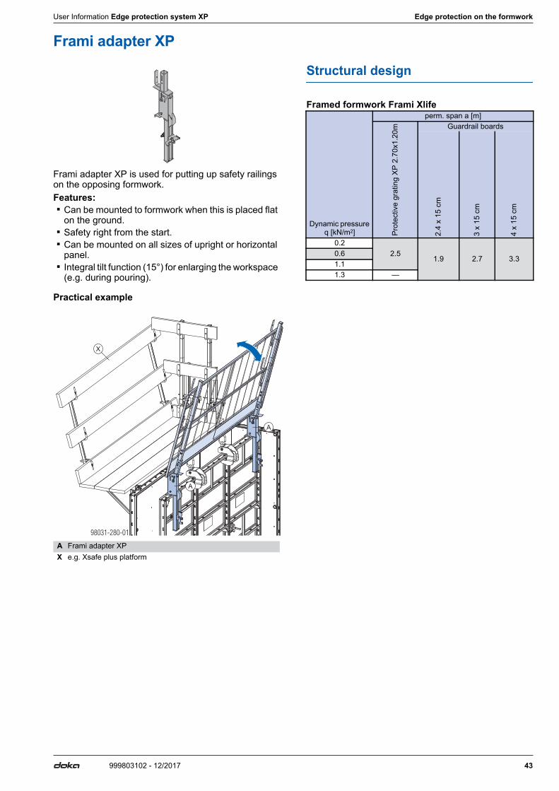
Frami adapter XP
Frami adapter XP is used for putting up safety railings on the opposing formwork.Features: ▪ Can be mounted to formwork when this is placed flat
on the ground. ▪ Safety right from the start. ▪ Can be mounted on all sizes of upright or horizontal
panel. ▪ Integral tilt function (15°) for enlarging the workspace
(e.g. during pouring).
Practical example
Structural design
Framed formwork Frami Xlife
A Frami adapter XPX e.g. Xsafe plus platform
98031-280-01
X
A
A
Dynamic pressure q [kN/m2]
perm. span a [m]
Prot
ectiv
e gr
atin
g XP
2.7
0x1.
20m Guardrail boards
2.4
x 15
cm
3 x
15 c
m
4 x
15 c
m
0.22.5
1.9 2.7 3.30.61.11.3 —

44 999803102 - 12/2017
Edge protection on the formwork User Information Edge protection system XP
Timber-beam formwork adapter XP
Timber-beam formwork adapter are used for putting up safety railings on the opposing formwork.Features: ▪ Can be installed on formwork laid flat on the ground. ▪ Safety right from the start. ▪ Can be used on all sizes of upright element. ▪ Integral tilt function (15°) for enlarging the workspace
(e.g. during pouring). ▪ With Circular formwork H20, there may be various
limitations due to different formwork radii and to the use of outside and inside elements.Separate checks must be made for each such pro-ject to establish whether the adapter can be used.
Practical example Large-area formwork Top 50
Structural design
Large-area formwork Top 50, Top 100 tec, FF20, FF100 tec and Circular formwork H20
A Timber-beam formwork adapter XP
Tr953-203-01
A
A
Dynamic pressure q [kN/m2]
perm. span a [m]
Prot
ectiv
e gr
atin
g XP
2.7
0x1.
20m Guardrail boards
2.4
x 15
cm
3 x
15 c
m
4 x
15 c
m
0.22.5
1.92.7 3.3
0.61.1 2.0 2.4 2.41.3 — 2.0 2.0

User Information Edge protection system XP Edge protection on the formwork
45999803102 - 12/2017
Bracket adapter XP FRR 50/30
The Bracket adapter XP FRR 50/30 is an alternative to the Handrail post 1.00m for mounting the Edge protec-tion system XP on platforms. ▪ for railing-heights of 1.20 m
Practical example with Framax bracket 90
Practical example with Frami adjustment frame
Practical example with Doka bridge edge beam formwork T
Structural design
A Bracket adapter XP FRR 50/30B Framax bracket 90C Handrail post XP 1.20mD Protective grating XP
A Bracket adapter XP FRR 50/30C Handrail post XP 1.20mD Protective grating XPE Frami adjustment frame
TR1126-200-01
A
B
C
D
TR1126-201-01
A
E
C
D
A Bracket adapter XP FRR 50/30C Handrail post XP 1.20mD Protective grating XPF Bridge edge beam support T 1.40m
The permitted influence widths of the brackets are not influenced by the Edge protection sys-tem XP. Follow the directions in the relevant User Infor-mation booklets!
TR1126-204-01
A
C
D
F

46 999803102 - 12/2017
Edge protection on the formwork User Information Edge protection system XP
Railing clamp XP 40cmThe Railing clamp XP 40cm is for clamping the Handrail post XP to the end face of concrete slabs or to Doka beams. ▪ for railing-heights of 1.20 m ▪ for railing heights 1.80 m with additional measures
Clamping range: 2 - 43 cm
Edge protection on floor-slab formwork
Railing-height 1.20 m
Assembly
Can be attached in the direction of either the secondary or primary beams.➤To adjust the clamping range of the Railing
clamp XP 40cm, first take the wedge out of the wedge-slot.
➤Push the Railing clamp XP 40cm onto the Doka beam until it is pressed against the end face of the slab.
➤Hammer in the wedge until the hammer rebounds.
WARNING➤Only clamp the Railing clamp XP 40cm to
components that can reliably transfer the forces involved!
WARNINGRisk of formwork beams tipping over!➤Only attach the Railing clamp XP 40cm to
formwork beams if there is no risk of these tipping over.
WARNINGRisk of breaking the formwork sheets!➤ It is forbidden to fasten the clamp to the
formwork sheeting only.
9776-221-01NOTICEWhen Railing clamp XP is installed at right angles to the beam, the beam must be securely seated in the recesses of the clamp.
A Top recessB Bottom recess
98031-255-02 98031-255-03
9 -233-01776
9 -232-01776
A
B

User Information Edge protection system XP Edge protection on the formwork
47999803102 - 12/2017
➤Position the fully pre-assembled beams as primary beams or secondary beams, as applicable.
a ... max. cantilever length of Doka beam H20 3.90m: 109.0 cm
➤Working from below, push the Toeboard holder XP onto the Handrail post XP (not needed when using the Protective grating XP).
➤Push the Handrail post XP into the post holder of the Railing clamp XP 40cm until the locking mechanism engages (= 'Easy-Click' function).
➤Fit on a Protective grating XP or guard-rail boards, and fix them in place.
Fixing in the direction of the secondary beams
Fixing in the direction of the primary beams
Usual on-site nailing of the formwork sheet: 1 nail/0.5 m2
a ... Protruding length of formwork sheet ≤ 5 cm
NOTICE ▪ Secure cantilevering beams to prevent lift-
out and tipover. ▪ The superstructure has to be completed
before the remaining steps in the railing assembly procedure are carried out.
The locking mechanism must engage.
Not possible for use with Protec-tive grating XP.
Can be mounted to formwork beam either with or without form-work sheet.
A Load action
9 -2 4-04776 1
a
98031-243-01
AA
9776-218-01
A
9776-216-01 9776-217-01
A
Only allowed to be mounted to formwork beams to which form-work sheeting is attached.
A Load action
9776-222-01
A
9776-223-01
A
9776-222-02
a

48 999803102 - 12/2017
Edge protection on the formwork User Information Edge protection system XP
Railing-height 1.80 m
For railing height 1.80m, also proceed in accordance with the instructions below when using the Railing clamp XP.
a ... 2.5 cm
a ... max. cantilever length of Doka beam H20 3.90m: 109.0 cm
Edge protection on Doka ready-to-use platforms
Edge protection on deck-boards
NOTICEInsertion of a hardwood packer on top of the Doka beam H20 is absolutely essential for safe transfer of the loads.
A Railing clamp XP 40cmB Hardwood packer 65x20x190 mmC Universal screw countersunk head Torx TG 5x80
WARNING➤ Installation at right angles to the beam is pro-
hibited when the railing height is 1.80 m.
Use on the primary beam Use on the secondary beam
A Railing clamp XP 40cmB Hardwood packer 65x20x190 mm (only for railing height 1.80 m)D Toeboard (plank 150 mm), site-providedE Secondary-beam stabilisers
9 -2 5-01776 1
BC
A
B
a a
9 -232-01776
B
D
A
9 -2 4-01776 1
a
B
E
A 9 -2 4-02776 1
a
NOTICE ▪ Min. cross section of deck-boards:
5 x 20 cm ▪ Make sure that the deck-boards are
screwed on adequately.
9803
1-24
5-01
98031-253-01 98031-253-02

User Information Edge protection system XP Edge protection on the formwork
49999803102 - 12/2017
Structural design
used in combination with Handrail post XP 1.20m
Used in direction of either secondary or primary beams
1) with toeboard 5 x 20 cm
Used on deck-boards 5 x 20 cm
1) with toeboard 3 x 20 cm, 4 x 20 cm or 5 x 20 cm2) with toeboard 5 x 20 cm
used in combination with Handrail post XP 1.20m and 0.60m or Handrail post XP 1.80m
Used in direction of either secondary or primary beams
Dynamic pressure q
[kN/m2]
Permissible influence width 'e' [m]
Prot
ectiv
e gr
atin
g XP
2.7
0x1.
20m Guard-rail boards
Scaf
fold
tube
s 48
.3m
m 1)
3 x
15
cm
4 x
15
cm
0.22.5
2.0 2.0 5.00.6 2.0 2.0 5.01.1 — — 3.51.3 2.2 — — 2.9
Dynamic pressure q
[kN/m2]
Permissible influence width 'e' [m]
Prot
ectiv
e gr
atin
g XP
2.7
0x1.
20m Guard-rail boards
Scaf
fold
tube
s 48
.3m
m 2)
2.5
x 12
.5
cm 1)
2.4
x 15
cm
3 x
15
cm
4 x
15
cm
3 x
20
cm
4 x
20
cm
5 x
20
cm
0.2
2.5
1.8 1.6 1.6 1.6 1.0 1.0 1.0 4.60.6 1.8 1.6 1.6 1.6 1.0 1.0 1.0 4.61.1 1.5 1.2 1.2 1.2 0.9 0.9 0.9 3.51.3 1.3 1.0 1.0 1.0 0.7 0.7 0.7 2.9
Dynamic pressure q
[kN/m2]
Permissible influ-ence width 'e' [m]
Prot
ectiv
e gr
atin
gs X
P 2.
70x1
.20m
and
2.
70x0
.60m
Scaf
fold
tube
s 48
.3m
m
0.2 2.0 2.00.6 2.0 2.01.1 — —1.3 — —
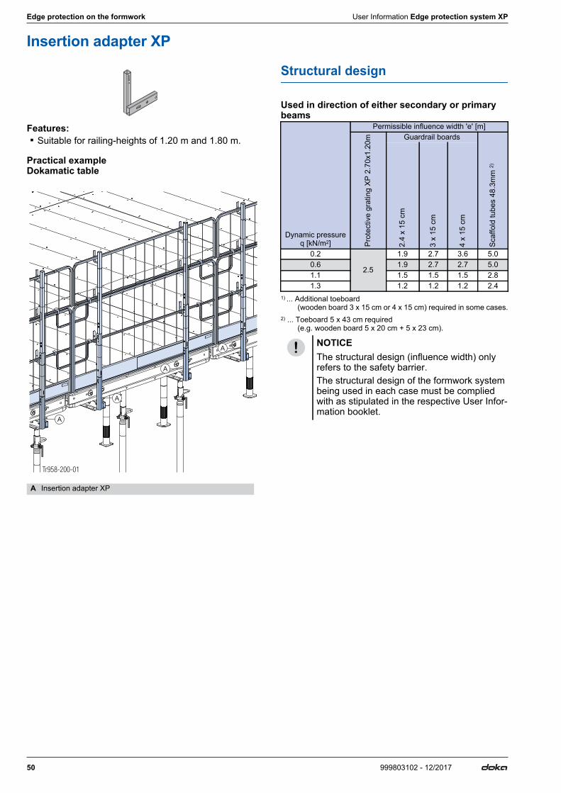
50 999803102 - 12/2017
Edge protection on the formwork User Information Edge protection system XP
Insertion adapter XP
Features: ▪ Suitable for railing-heights of 1.20 m and 1.80 m.
Practical example Dokamatic table
Structural design
Used in direction of either secondary or primary beams
1) ... Additional toeboard (wooden board 3 x 15 cm or 4 x 15 cm) required in some cases.2) ... Toeboard 5 x 43 cm required (e.g. wooden board 5 x 20 cm + 5 x 23 cm).
A Insertion adapter XP
Tr958-200-01
A
A
A
A
Dynamic pressure q [kN/m2]
Permissible influence width 'e' [m]
Prot
ectiv
e gr
atin
g XP
2.7
0x1.
20m Guardrail boards
Scaf
fold
tube
s 48
.3m
m 2)
2.4
x 15
cm
3 x
15 c
m
4 x
15 c
m
0.2
2.5
1.9 2.7 3.6 5.00.6 1.9 2.7 2.7 5.01.1 1.5 1.5 1.5 2.81.3 1.2 1.2 1.2 2.4
NOTICEThe structural design (influence width) only refers to the safety barrier.The structural design of the formwork system being used in each case must be complied with as stipulated in the respective User Infor-mation booklet.

User Information Edge protection system XP Edge protection on the formwork
51999803102 - 12/2017
Dokamatic adapter XP
The Dokamatic adapter XP makes it possible to attach a Handrail post XP to a Dokamatic table. ▪ Suitable for all sizes of table. ▪ Integrated lowering function:
- Tables can be stacked and stored without having to dismount the Dokamatic adapters XP.
- Tables can be placed next to one another even if there are Dokamatic adapters XP mounted along abutting edges.
▪ Suitable for railing heights of 1.20 m and 1.80 m. ▪ When bolted in place, they are suitable for both
lengthways and sideways safety barriers.
Note:Mount the sideguards while the table elements (to which the Dokamatic table platforms have previously been mounted) are still on the stack.
Assembly
Possible positions on the Dokamatic table waling
The positions B and C shown here only apply to standard tables. On tables with 2 or 4 intermediate props, positions B and C may be changed as needed.
➤Bolt the Dokamatic adapter XP to the desired posi-tion on the Dokamatic table waling with 2 connecting pins and secure these with spring cotters.
➤Use a hammer to pull out the recessed adapter-piece until the locking mechanism engages.
➤Push the Handrail post XP into the adapter until the locking mechanism engages ('Easy-Click' function).
➤Mount the safety barriers (see the section headed "Mounting the safety barriers").
Dismantling
➤Slightly lift the Handrail post XP and press in the bot-tom locking mechanism.
➤Lower the Handrail post XP. This deactivates the Easy-Click function.
➤Then pull out the Handrail post XP straight upwards.
A Standard upright for lengthways or sideways safety barrierB Extra upright for lengthways safety barrierC Extra upright for lengthways AND sideways safety barrier
Installation situation of the Dokamatic adapteron 2.00m wide tables on 2.50m wide tables
A Dokamatic adapter XP
98031-276-01
A ABC C
98031-267-01
A
98031-266-01
A
Alignment of Handrail post XP for sideways safety barrier
Alignment of Handrail post XP for lengthways safety barrier
▪ The locking mechanism must engage. ▪ The handrail-post plates must be facing
towards the inside of the barrier.
98031-268-01
98031-269-01 98031-277-01
98031-270-01

52 999803102 - 12/2017
Edge protection on the formwork User Information Edge protection system XP
Mounting the safety barriers
with Protective gratings XP
Recommended lengths of grating
1) only 1 Handrail post XP required in middle
Practical examples
Note:The safety barrier can also be erected with guard-rail boards or scaffold tubes.
Dokamatic table2.00x4.00m 2.00x5.00m 2.50x4.00m 2.50x5.00m
Sideways 2.00m 2.00m 2.50m 2.50m
Lengthways 2.00 + 2.50m 1)
2.50 + 2.70m 1)
2.00 + 2.50m 1)
2.50 + 2.70m 1)
Sideways safety barrierDokamatic table 2.00x4.00m Dokamatic table 2.50x5.00m
Lengthways safety barrierDokamatic table 2.00x4.00m Dokamatic table 2.00x5.00m
Corner safety barrier
A Standard upright for lengthways or sideways safety barrierB Extra upright for lengthways safety barrierC Extra upright for lengthways AND sideways safety barrier
98031-273-01
200
A
A
98031-271-01
A 250
A
98031-272-01
200
250
A
B
A
98031-274-01
250
270
A
B
A
98031-275-01
200
250 250
A
B
C A
A

User Information Edge protection system XP Edge protection on the formwork
53999803102 - 12/2017
Structural design
used in combination with Handrail post XP 1.20m
1) with toeboard 3 x 20 cm, 4 x 20 cm or 5 x 20 cm2) with toeboard 5 x 20 cm
used in combination with Handrail post XP 1.20m and 0.60m or Handrail post XP 1.80m
1) with toeboard 3 x 20 cm, 4 x 20 cm or 5 x 20 cm2) with toeboard 5 x 20 cm
Dynamic pressure q
[kN/m2]
Permissible influence width 'e' [m]Pr
otec
tive
grat
ing
XP
2.70
x1.2
0mGuard-rail boards
Scaf
fold
tube
s 48
.3m
m 2)
Gap
-free
boa
rdin
g
2.5
x 12
.5
cm 1)
2.4
x 15
cm
3 x
15
cm
4 x
15
cm
3 x
20
cm
4 x
20
cm
5 x
20
cm
0.2
2.5
1.8 1.9 2.7 3.6 2.9 3.4 3.4 5.0 1.80.6 1.8 1.9 2.7 3.3 2.4 2.4 2.4 5.0 1.31.1 1.8 1.8 1.8 1.8 1.3 1.3 1.3 5.0 0.71.3 1.8 1.5 1.5 1.5 1.1 1.1 1.1 4.4 0.6
Dynamic pressure q
[kN/m2]
Permissible influence width 'e' [m]
Prot
ectiv
e gr
atin
g XP
2.7
0x1.
20m
an
d 2.
70x0
.60m
Guard-rail boards
Scaf
fold
tube
s 48
.3m
m 2)
Gap
-free
boa
rdin
g
2.5
x 12
.5
cm 1)
2.4
x 15
cm
3 x
15
cm
4 x
15
cm
3 x
20
cm
4 x
20
cm
5 x
20
cm
0.2
2.5
1.8 1.9 2.7 3.6 2.9 3.3 3.3 5.0 1.50.6 1.8 1.9 2.7 2.8 2.1 2.1 2.1 5.0 0.91.1 1.8 1.5 1.5 1.5 1.1 1.1 1.1 3.7 0.51.3 1.6 1.3 1.3 1.3 1.0 1.0 1.0 3.2 0.4

54 999803102 - 12/2017
Edge protection on the formwork User Information Edge protection system XP
Dokadek handrail-post shoes
The Dokadek handrail-post shoes enable Handrail posts XP 1.20m to be secured to the Dokadek panel.Features: ▪ For longside and shortside safety barriers, with or
without transfer of concreting loads (depending on which handrail post shoe is used).
▪ Suitable for a railing-height of 1.20 m.
Example of use with Dokadek handrail post shoe short
Example of use with Dokadek handrail post shoe short
Dokadek handrail-post shoe short
Dokadek handrail-post shoe - long
Dokadek handrail-post shoe short 1.20m
Dokadek handrail-post shoe long 1.20m
Dokadek 20 handrail-post shoe long 1.20m
A Dokadek handrail-post shoe shortC Handrail post XP 1.20mD Protective grating XP 2.70x1.20mE Toeboard holder XP 0.60mF Toeboard
9803
3-27
0-01
C
D
A
E
F
A Dokadek handrail-post shoe - longC Handrail post XP 1.20mE Toeboard holder XP 0.60mF ToeboardG Toeboard holder XP 1.20mH Guardrail boards
98033-366-01
H
A
C
E
F
G

User Information Edge protection system XP Edge protection on the formwork
55999803102 - 12/2017
Structural design with Dokadek 30
Dokadek handrail-post shoe short 1.20m and Dokadek handrail-post shoe long
Permitted influence width [cm] of the handrail-post shoes for slab thicknesses of up to 32 cm (without additional precautions)
1) Minimum thickness 3 cm for influence width greater than 137 cm.
Permitted influence width [cm] of the handrail-post shoes for slab thicknesses of up to 50 cm (with additional precautions)
1) Minimum thickness 3 cm for influence width greater than 137 cm.2) Guardrail boards 15 cm are only permitted up to a slab thickness of 45 cm.
Dokadek handrail-post shoe short 1.20m and Dokadek handrail-post shoe long 1.20m
Permitted influence widths [cm] of the handrail-post shoes
1) Minimum thickness 3 cm for influence width greater than 137 cm.
Structural design with Dokadek 20
Dokadek handrail-post shoe short 1.20m and Dokadek 20 handrail-post shoe long 1.20m
Permitted influence widths [cm] of the handrail-post shoes
1) Min. section thickness 2.0 mm for steel grade S355 Min. section thickness 2.0 mm for steel grade S235
Type of railingG
uard
rail
boar
d 15
cm
1)
Gua
rdra
il bo
ard
20
cm1)
Scaf
fold
tube
48.
3mm
Prot
ectiv
e gr
atin
g XP
2.
70x1
.20m
Dynamic pressure q [kN/m2] With concrete load
0.2 137 137 137 137without concrete load
0.2 259 259 259 2590.6 259 137 259 2591.1 137 — 259 2591.3 — — 259 244
Type of railing
Gua
rdra
il bo
ard
15
cm1)
2)
Gua
rdra
il bo
ard
20
cm1)
2)
Prot
ectiv
e gr
atin
g XP
2.
70x1
.20m
Dynamic pressure q [kN/m2] With concrete load
0.2 137 2) 137 137without concrete load
0.2 259 2) 259 2590.6 259 2) 137 2591.1 137 2) — 2591.3 — — 244
Type of railing
Gua
rdra
il bo
ard
15
cm1)
Gua
rdra
il bo
ard
20
cm1)
Scaf
fold
tube
48.
3mm
Prot
ectiv
e gr
atin
g XP
2.
70x1
.20m
Dynamic pressure q [kN/m2] without concrete load
0.2 259 259 259 2590.6 259 137 259 2591.1 137 — 259 2591.3 — — 259 244
Type of railing
Gua
rdra
il bo
ard
15
cm
Gua
rdra
il bo
ard
20
cm
Scaf
fold
tube
48.
3mm
Prot
ectiv
e gr
atin
g XP
2.
50x1
.20m
Scaf
fold
tube
d33
.7m
m1)
Dynamic pressure q [kN/m2] without concrete load
0.2 200 200 200 200 2000.6 200 100 200 200 2001.1 100 — 200 200 2001.3 — — 200 200 200

56 999803102 - 12/2017
Edge protection on the formwork User Information Edge protection system XP
Overview of safety-barrier heights with slab formwork
Dokaflex
Railing clamp XP 40cm
Insertion adapter XP
1) Parallel to the primary beams2) Parallel to the secondary beams
Dokamatic table
Dokamatic adapter XP
Insertion adapter XP
Panel floor formwork
Panel floor formwork Dokadek 30
Panel floor formwork Dokadek 20
Dimensions in cm
Type of railing
Longside safety barri-er1) with
Handrail post XP
Shortside safety barri-er2) with
Handrail post XP
1.20m 1.20m+0.60mor 1.80m 1.20m 1.20m+0.60m
or 1.80mGuardrail board 15 cm 118 176 — —
Guardrail board 20 cm 123 181 103 —
Scaffold tube 48.3mm 109 166 — 146
Scaffold tube 33.7mm 109 167 — 147
Protective grating XP 111 168 — 148
Type of railing
Longside safety barri-er1) with
Handrail post XP
Shortside safety barri-er2) with
Handrail post XP
1.20m 1.20m+0.60mor 1.80m 1.20m 1.20m+0.60m
or 1.80mGuardrail board 15 cm 134 191 113 171
Guardrail board 20 cm 139 196 118 176
Scaffold tube 48.3mm 124 181 104 161
Scaffold tube 33.7mm 124 182 104 162
Protective grating XP 129 186 102 163
Type of railing
Longside safety bar-rier with
Handrail post XP
Shortside safety bar-rier with
Handrail post XP
1.20m 1.20m+0.60mor 1.80m 1.20m 1.20m+0.60m
or 1.80mGuardrail board 15 cm 118 176 118 176
Guardrail board 20 cm 123 181 123 181
Scaffold tube 48.3mm 109 167 109 167
Scaffold tube 33.7mm 109 167 109 167
Protective grating XP 114 170 114 170
Type of railing
Longside safety bar-rier with
Handrail post XP
Shortside safety bar-rier with
Handrail post XP
1.20m 1.20m+0.60mor 1.80m 1.20m 1.20m+0.60m
or 1.80mGuardrail board 15 cm 134 191 118 176
Guardrail board 20 cm 139 196 123 181
Scaffold tube 48.3mm 124 181 109 167
Scaffold tube 33.7mm 124 182 109 167
Protective grating XP 129 186 114 170
Type of railing
Longside safety bar-rier with
Handrail post XP 1.20m and
Shortside safety bar-rier with
Handrail post XP 1.20m and
Dok
adek
ha
ndra
il-po
st s
hoe
long
Dok
adek
ha
ndra
il-po
st s
hoe
long
1.
20m
Dok
adek
ha
ndra
il-po
st s
hoe
shor
t
Dok
adek
ha
ndra
il-po
st s
hoe
shor
t 1.
20m
Guardrail board 15 cm 149 120 149 120
Guardrail board 20 cm 154 125 154 125
Scaffold tube 48.3mm 140 112 140 112
Scaffold tube 33.7mm 140 111 140 111
Protective grating XP 2.50x1.20m 157 114 157 114
Type of railing
Longside safety bar-rier with
Handrail post XP 1.20m and
Shortside safety bar-rier with
Handrail post XP 1.20m and
Dok
adek
20
hand
rail-
post
sho
e lo
ng
1.2
0m
Dok
adek
ha
ndra
il-po
st s
hoe
shor
t
Dok
adek
ha
ndra
il-po
st s
hoe
shor
t 1.
20m
Guardrail board 15 cm 120 149 120
Guardrail board 20 cm 125 154 125
Scaffold tube 48.3mm 112 140 112
Scaffold tube 33.7mm 111 140 111
Protective grating XP 2.50x1.20m 114 157 114

User Information Edge protection system XP Additional areas of use
57999803102 - 12/2017
Additional areas of useSafety barriers on parapets
The Parapet adapter XP allows the Edge protection system XP to be mounted on parapets (only reinforced-concrete parapets that are between 12 cm and 43 cm thick).This makes it possible to put up safety barriers of 1.20 m or 0.60 m in height.Possible types of safety barrier: ▪ Protective grating XP ▪ Guardrail boards ▪ Scaffold tubes ▪ Gap-free boarding
Assembly
➤Push the Parapet adapter XP into the profile of the Railing clamp XP and secure it with a Spring cotter d5 (included with product).
➤To adjust the clamping range of the Railing clamp XP 40cm, first take the wedge out of the wedge-slot.
➤Mount the Parapet adapter XP to the parapet with the Railing clamp XP.
➤Hammer in the wedge until the hammer rebounds.➤Push on the Handrail post XP 1.20m until it locks
("Easy-Click" function).
➤Mount the safety barriers (see the section headed "Mounting the safety barriers").
Structural design
The permitted influence widths are the same as those for the Railing clamp XP 40cm (see the section headed 'Edge protection on the structure – railing-height 1.20 m - Structural design').These data are also permissible for a railing-height of 0.60 m.
Practical examples
with Protective grating XP 2.70x1.20m and Protec-tive grating XP 1.20m
with Protective grating XP 2.70x0.60m and Protec-tive grating XP 0.60m
A Parapet adapter XPB Railing clamp XP 40cmC Spring cotter d5D Handrail post XP 1.20m or 0.60m
Tr904-200-02
A
B
C
D
B
Tr90
4-20
0-05A
▪ The locking mechanism must engage. ▪ The handrail-post plates must be facing
towards the inside of the building.
NOTICESecure the Protective grating XP 2.70x0.60m against accidental lift-out with a Velcro fas-tener (E) (included with product).
Tr904-201-01
Tr904-205-01
E

58 999803102 - 12/2017
Additional areas of use User Information Edge protection system XP
Fixing to steel components
The Weld-on connecting piece XP can be used for fix-ing the Handrail post XP to steel components.
Practical examples
h ... 5 cm
Structural design
Railing-height 1.20 m
1) with toeboard 3 x 20 cm, 4 x 20 cm or 5 x 20 cm2) with toeboard 5 x 20 cm
Railing-height 1.80 m
1) with toeboard 3 x 20 cm, 4 x 20 cm or 5 x 20 cm2) with toeboard 5 x 20 cm
WARNING➤For all fixing-situations other than those
shown here, the weld-seam must be individ-ually designed in each case.
➤Make sure that the Weld-on connecting piece XP is attached in the correct mounting position!
➤Observe all the standards and regulations applying to on-site welding work!
➤The Weld-on connecting piece XP must be welded onto the steel component with a fillet weld (a = 4 mm) on all 4 sides.
➤Only fix the Weld-on connecting piece XP to steel parts that can reliably transfer the forces involved.
Underside of Weld-on connect-ing piece XP welded to e.g. an I-
section girder
Rear of Weld-on connecting piece XP welded to e.g. a
squared tube
A Weld-on connecting piece XPB Decking board
98031-237-01
AB
98031-237-02
A
h
B
Dynamic pres-sure q[kN/m2]
Permissible influence width 'e' [m]
Prot
ectiv
e gr
atin
g XP
2.7
0x1.
20m Guard-rail boards
Scaf
fold
tube
s 48
.3m
m 2)
Gap
-free
boa
rdin
g
2.5
x 12
.5
cm 1)
2.4
x 15
cm
3 x
15
cm
4 x
15
cm
3 x
20
cm
4 x
20
cm
5 x
20
cm
0.2
2.5
1.8 1.9 2.7 3.6 2.9 3.4 3.4 5.0 1.80.6 1.8 1.9 2.7 3.3 2.4 2.4 2.4 5.0 1.31.1 1.8 1.8 1.8 1.8 1.3 1.3 1.3 5.0 0.71.3 1.6 1.5 1.5 1.5 1.1 1.1 1.1 4.4 0.6
Acting moment MEd: 112 kNcm
Dynamic pressure q
[kN/m2]
Permissible influence width 'e' [m]
Prot
ectiv
e gr
atin
g XP
2.7
0x1.
20m
an
d 2.
70x0
.60m
Guard-rail boards
Scaf
fold
tube
s 48
.3m
m 2)
Gap
-free
boa
rdin
g
2.5
x 12
.5
cm 1)
2.4
x 15
cm
3 x
15
cm
4 x
15
cm
3 x
20
cm
4 x
20
cm
5 x
20
cm
0.2
2.5
1.8 1.9 2.7 3.6 2.9 3.3 3.3 5.0 1.50.6 1.8 1.9 2.7 2.8 2.1 2.1 2.1 5.0 0.91.1 1.8 1.5 1.5 1.5 1.1 1.1 1.1 3.7 0.51.3 1.6 1.3 1.3 1.3 1.0 1.0 1.0 3.2 0.4
Acting moment MEd: 191 kNcm

User Information Edge protection system XP Additional areas of use
59999803102 - 12/2017
Safety barriers on sheeting walls
The Sheet pile adapter XP is for erecting safety barriers on sheeting walls. ▪ For sheeting wall thicknesses from 10 - 20 mm. ▪ Suitable for railing-heights of up to 1.20 m.
Practical example
Assembly
➤Push Sheet pile adapter XP down on to the sheeting wall.
➤Use a hammer to tighten the toggle clamp.
Structural design
Railing-height 1.20 m
1) with toeboard 3 x 20 cm, 4 x 20 cm or 5 x 20 cm2) with toeboard 5 x 20 cm
A Sheet pile adapter XPB Sheeting wall
Make sure that the adapter is seated firmly against the top of the sheeting wall!
A Sheet pile adapter XPB Sheeting wallC Toggle clamp
TR1067-200-01a
A
A
B
TR10
67-2
01-0
1
A
CB
Dynamic pres-sure q [kN/m2]
Permissible influence width 'e' [m]
Prot
ectiv
e gr
atin
g XP
2.7
0x1.
20m Guardrail boards
Scaf
fold
tube
s 48
.3m
m 2)
2.5
x 12
.5 c
m 1)
2.4
x 15
cm
3 x
15 c
m
4 x
15 c
m
3 x
20 c
m
4 x
20 c
m
5 x
20 c
m
0.22.5
1.8 1.9 2.1 2.1 1.3 1.3 1.3 5.00.6 1.8 1.9 2.1 2.1 1.3 1.3 1.3 5.01.1 1.5 1.3 1.3 1.3 0.9 0.9 0.9 3.31.3 2.3 1.3 1.1 1.1 1.1 0.8 0.8 0.8 2.8
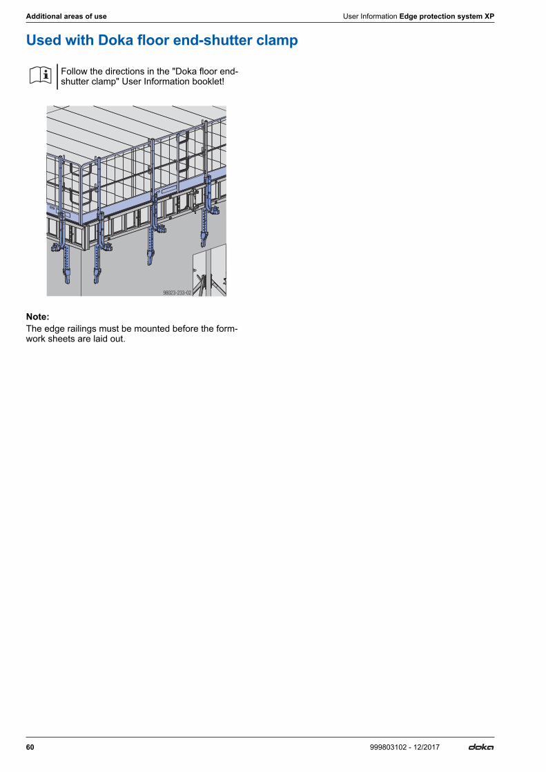
60 999803102 - 12/2017
Additional areas of use User Information Edge protection system XP
Used with Doka floor end-shutter clamp
Note:The edge railings must be mounted before the form-work sheets are laid out.
Follow the directions in the "Doka floor end-shutter clamp" User Information booklet!
98023-233-02

User Information Edge protection system XP Additional areas of use
61999803102 - 12/2017
Demarcation of work-zonesWhen combined with fence-feet baseblocks, the Edge protection system XP can also be used to demarcate different working areas within a jobsite.Required spacing of the handrail posts: 2.50 m (as the Protective gratings XP have to be mounted in a higher position).Requirements for fence-feet baseblocks: ▪ Dead weight min. 25 kg; length of baseblock foot
80 cm ▪ Recess for 40 x 40 mm squared tube
b ... 250 cmh ... max. 130 cmA Fence-feet baseblock (site-provided)B Handrail post XP 1.20mC Protective grating XP 2.70x1.20m
NOTICE ▪ This demarcation fence is not a guardrail
system as defined by EN 13374! ▪ Ensure that it has sufficient stability against
overturning, and allow for wind loads! ▪ When used as a safety guard and demarca-
tion fence for fall-hazard locations, it must be placed min. 2.00 m from the drop-off edge!
▪ Observe all local Standards and regula-tions!
98031-234-01
h
b
A
B
C

62 999803102 - 12/2017
General remarks User Information Edge protection system XP
General remarksIndividual design options
Mounting advertising signboards
Advertising signboards can be attached to the Protec-tive grating XP on-site.
Note:In cases where the edge protection is designed with gap-free boarding, the points mentioned above no longer apply.
Practical example
a ... 200 cmb ... 100 cm
Colour scheme and customer logo
▪ Protective gratings XP can be ordered in various col-ours (all RAL colours possible). They are galvanised and one side is powder-coated.
▪ On request, the empty area on the left-hand side (A) of the toeboard can also be used for affixing cus-tomer stickers.
For more information, please contact your Doka techni-cian.
NOTICE ▪ It is only allowed to fit signboards to 1.20 m
high Protective gratings XP. ▪ On Protective gratings XP being used for
structure-mounted safety barriers, sign-boards are only allowed if the gratings are fixed with Railing clamps XP or Handrail-post shoes XP.
▪ Size of signboard (width x height): max. 2.00x1.00m
▪ Dynamic pressure q: max. 0.6 kN/m2
▪ Always fix the signboard to the grating-bar side (provides a better support surface so signboard can be fixed more firmly).
- This means that the Protective grating XP has to be mounted the other way round (i.e. turned 180° with Doka logo on toeboard facing inwards).
▪ Mounting signboards on two adjacent Pro-tective gratings XP is not allowed (must be spaced at least one grating apart).
▪ Fasten the signboard to the Protective grating XP centrally, using cable ties.
- Tie it 4x at the top, 6x in the middle and 4x at the bottom, (only applies to sign-boards measuring 2.00x1.00 m).
▪ The holes for fixing the signboard must be drilled on-site.
▪ Vertical stacking with Protective gratings XP 0.60m is still possible.
▪ The stacking height will depend on how thick the advertising signboard is.
▪ When the signboards are stacked, some of them may end up being scratched.
Alternatively, advertising nets or tarpaulins can also be attached (attachment method will depend on the type of net or tarp).
A Protective grating XP 2.70x1.20mB Advertising signboard, 2.00x1.00mC Fixing points for cable ties (width min. 4.6 mm)
Tr903-200-01
A B C
a
bTr960-200-01
A

User Information Edge protection system XP General remarks
63999803102 - 12/2017
Transporting, stacking and storing
Bundling the Protective gratings XP
➤Use metal banding to strap max. 38 Protective gratings XP together with 3 battens of hardwood blocking.
h ... 105 cm
The integral stacking stirrups prevent the Protective gratings XP from slipping.
A Stacking stirrup
98031-221-01
h
98031-221-02
A

64 999803102 - 12/2017
General remarks User Information Edge protection system XP
Doka multi-trip packaging
Doka skeleton transport box 1.70x0.80m
Storage and transport devices for small items: ▪ durable ▪ stackableSuitable transport appliances: ▪ crane ▪ pallet stacking truck ▪ forklift truckTo make the Doka skeleton transport box easier to load and unload, one of its sidewalls can be opened.
Using Doka skeleton transport boxes 1.70x0.80m as storage units
Max. n° of boxes on top of one another
Using Doka skeleton transport boxes 1.70x0.80m as transport devices
Lifting by crane
Repositioning by forklift truck or pallet stacking truck
The forks can be inserted under either the broadside or the narrowside of the containers.
Utilise the benefits of Doka multi-trip packaging on your site.Multi-trip packaging such as containers, stacking pal-lets and skeleton transport boxes keep everything in place on the site, minimise time wasted searching for parts, and streamline the storage and transport of sys-tem components, small items and accessories.
Max. load: 700 kg (1540 lbs)Permitted imposed load: 3150 kg (6950 lbs)
NOTICE ▪ Multi-trip packaging items that each contain
very different loads must be stacked with the heaviest ones at the bottom and the lightest ones at the top!
▪ Rating plate must be in place and clearly legible
Outdoors (on the site) IndoorsFloor gradient up to 3% Floor gradient up to 1%
2 5It is not allowed to stack empty pallets on top of one another!
NOTICE ▪ Multi-trip packaging items may only be lifted
one at a time. ▪ Only lift the boxes when their sidewalls are
closed! ▪ Use a suitable lifting chain
(e.g. Doka 4-part chain 3.20m). Do not exceed the permitted load-bearing capacity.
▪ Spread-angle β max. 30°!
9234-203-01

User Information Edge protection system XP General remarks
65999803102 - 12/2017
Doka multi-trip transport box 1.20x0.80m galv.
Storage and transport devices for small items: ▪ durable ▪ stackableSuitable transport appliances: ▪ crane ▪ pallet stacking truck ▪ forklift truck
Using Doka multi-trip transport boxes as storage units
Max. n° of boxes on top of one another
Using Doka multi-trip transport boxes as transport devices
Lifting by crane
Repositioning by forklift truck or pallet stacking truck
The forks can be inserted under either the broadside or the narrowside of the containers.
Multi-trip transport box partition
Different items in the Multi-trip transport box can be kept separate with the Multi-trip transport box partitions 1.20m or 0.80m.
Possible ways of dividing the box
Max. load: 1500 kg (3300 lbs)Permitted imposed load: 7850 kg (17305 lbs)
NOTICE ▪ Multi-trip packaging items that each contain
very different loads must be stacked with the heaviest ones at the bottom and the lightest ones at the top!
▪ Rating plate must be in place and clearly legible
Outdoors (on the site) IndoorsFloor gradient up to 3% Floor gradient up to 1%
3 6It is not allowed to stack empty pallets on top of one another!
NOTICE ▪ Multi-trip packaging items may only be lifted
one at a time. ▪ Use a suitable crane suspension tackle
(e.g. Doka 4-part chain 3.20m). Do not exceed the permitted load-bearing capacity.
▪ Spread angle β max. 30°!
A Slide-bolt for fixing the partition
Multi-trip transport box partition Lengthways Crossways
1.20m max. 3 partitions -0.80m - max. 3 partitions
9206-202-01
Tr75
5-20
0-02
A
Tr755-200-04 Tr755-200-05

66 999803102 - 12/2017
General remarks User Information Edge protection system XP
Doka stacking pallet 1.55x0.85m and 1.20x0.80m
Storage and transport devices for long items: ▪ durable ▪ stackableSuitable transport appliances: ▪ crane ▪ pallet stacking truck ▪ forklift truck
Using Doka stacking pallets as storage units
Max. n° of units on top of one another
Note:How to use with bolt-on castor set: Always apply the fixing brake when the container is ‘parked’.When Doka stacking pallets are stacked, the bottom pallet must NOT be one with a bolt-on caster set mounted to it.
Using Doka stacking pallets as transport devices
Lifting by crane
Repositioning by forklift truck or pallet stacking truck
Max. load: 1100 kg (2420 lbs)Permitted imposed load: 5900 kg (12980 lbs)
NOTICE ▪ Multi-trip packaging items that each contain
very different loads must be stacked with the heaviest ones at the bottom and the lightest ones at the top!
▪ Rating plate must be in place and clearly legible
Outdoors (on the site) IndoorsFloor gradients of up to 3% Floor gradients of up to 1%
2 6It is not allowed to stack empty pallets on top of one another!
NOTICE ▪ Multi-trip packaging items may only be lifted
one at a time. ▪ Use a suitable lifting chain
(e.g. Doka 4-part chain 3.20m). Do not exceed the permitted load-bearing capacity.
▪ Load the items centrically. ▪ Fasten the load to the stacking pallet so that
it cannot slide or tip out. ▪ Spread-angle β max. 30°!
aDoka stacking pallet 1.55x0.85m max. 4.0 mDoka stacking pallet 1.20x0.80m max. 3.0 m
NOTICE ▪ Load the items centrically. ▪ Fasten the load to the stacking pallet so that
it cannot slide or tip out.
92815-2 -0124
a
= =

User Information Edge protection system XP General remarks
67999803102 - 12/2017
Doka accessory box
Storage and transport devices for small items: ▪ durable ▪ stackableSuitable transport appliances: ▪ crane ▪ pallet stacking truck ▪ forklift truckThe Doka accessory box is the tidy, easy-to-find way of storing and stacking all interconnection and form-tie components.
Doka accessory boxes as storage units
Max. n° of boxes on top of one another
Note:How to use with bolt-on castor set: Always apply the fixing brake when the container is "parked".When Doka accessory boxes are stacked, the bottom box must NOT be one with a bolt-on castor set mounted to it.
Doka accessory box as transport devices
Lifting by crane
Repositioning by forklift truck or pallet stacking truck
The forks can be inserted under either the broadside or the narrowside of the containers.
Bolt-on castor set B
The Bolt-on caster set B turns the stacking pallet into a fast and manoeuvrable transport trolley.Suitable for drive-through access openings > 90 cm.
The Bolt-on caster set B can be mounted to the follow-ing multi-trip packaging items: ▪ Doka accessory box ▪ Doka stacking pallets
Max. load: 1000 kg (2200 lbs)Permitted imposed load: 5530 kg (12191 lbs)
NOTICE ▪ Multi-trip packaging items that each contain
very different loads must be stacked with the heaviest ones at the bottom and the lightest ones at the top!
▪ Rating plate must be in place and clearly legible
Outdoors (on the site) IndoorsFloor gradient up to 3% Floor gradient up to 1%
3 6It is not allowed to stack empty pallets on top of one another!
NOTICE ▪ Multi-trip packaging items may only be lifted
one at a time. ▪ Use a suitable lifting chain
(e.g. Doka 4-part chain 3.20m). Do not exceed the permitted load-bearing capacity.
▪ Spread angle β max. 30°!
Follow the directions in the Operating Instruc-tions!
92816-206-01

Article n°[kg] Article n°[kg]
68 999803102 - 12/2017
Component overview User Information Edge protection system XP
Component overview[kg]Article n°
Handrail post XP 1.20m 4.1 586460000Geländersteher XP 1,20m
Toeboard holder XP 1.20m 0.64 586461000Fußwehrhalter XP 1,20m
Handrail post XP 0.60m 5.0 586462000Geländersteher XP 0,60m
Toeboard holder XP 0.60m 0.77 586463000Fußwehrhalter XP 0,60m
Handrail post XP 1.80m 7.0 586482000Geländersteher XP 1,80m
Railing clamp XP 40cm 7.7 586456000Geländerzwinge XP 40cm
Railing clamp XP 85cm 9.3 586468000Geländerzwinge XP 85cm
Handrail-post shoe XP 2.2 586457000Geländerschuh XP
Handrail-post shoe XP box-out 0.18 586480000Aussparung Geländerschuh XP
Screw-on shoe XP 1.5 586458000Schraubschuh XP
Screw sleeve 20.0 0.03 584386000Schraubhülse 20,0
Attachable sleeve 24mm 0.03 584385000Steckhülse 24mm
Step bracket XP 1.6 586459000Treppenkonsole XP
Framax adapter XP 8.0 586475000Framax-Adapter XP
GalvanisedHeight: 118 cm
GalvanisedHeight: 21 cm
GalvanisedHeight: 68 cm
GalvanisedHeight: 21 cm
GalvanisedHeight: 176 cm
GalvanisedHeight: 73 cm
GalvanisedHeight: 115 cm
GalvanisedLength: 20 cm
BlackLength: 25.8 cmWidth: 24.4 cmHeight: 5.5 cm
GalvanisedHeight: 27 cm
PPYellowLength: 20 cmDiameter: 3.1 cm
PVCPEGreyLength: 16.5 cmDiameter: 2.7 cm
GalvanisedHeight: 27 cm
GalvanisedHeight: 56 cm
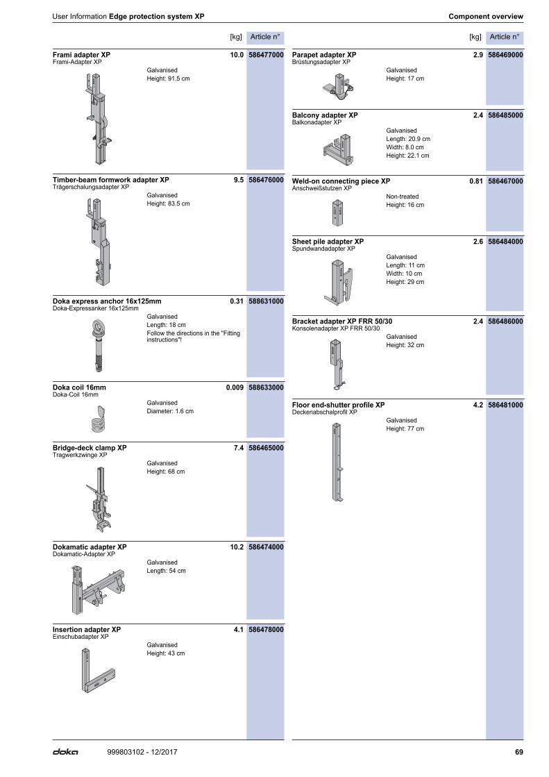
Article n°[kg] Article n°[kg]
69999803102 - 12/2017
User Information Edge protection system XP Component overview
Frami adapter XP 10.0 586477000Frami-Adapter XP
Timber-beam formwork adapter XP 9.5 586476000Trägerschalungsadapter XP
Doka express anchor 16x125mm 0.31 588631000Doka-Expressanker 16x125mm
Doka coil 16mm 0.009 588633000Doka-Coil 16mm
Bridge-deck clamp XP 7.4 586465000Tragwerkzwinge XP
Dokamatic adapter XP 10.2 586474000Dokamatic-Adapter XP
Insertion adapter XP 4.1 586478000Einschubadapter XP
Parapet adapter XP 2.9 586469000Brüstungsadapter XP
Balcony adapter XP 2.4 586485000Balkonadapter XP
Weld-on connecting piece XP 0.81 586467000Anschweißstutzen XP
Sheet pile adapter XP 2.6 586484000Spundwandadapter XP
Bracket adapter XP FRR 50/30 2.4 586486000Konsolenadapter XP FRR 50/30
Floor end-shutter profile XP 4.2 586481000Deckenabschalprofil XP
GalvanisedHeight: 91.5 cm
GalvanisedHeight: 83.5 cm
GalvanisedLength: 18 cmFollow the directions in the "Fitting instructions"!
GalvanisedDiameter: 1.6 cm
GalvanisedHeight: 68 cm
GalvanisedLength: 54 cm
GalvanisedHeight: 43 cm
GalvanisedHeight: 17 cm
GalvanisedLength: 20.9 cmWidth: 8.0 cmHeight: 22.1 cm
Non-treatedHeight: 16 cm
GalvanisedLength: 11 cmWidth: 10 cmHeight: 29 cm
GalvanisedHeight: 32 cm
GalvanisedHeight: 77 cm

Article n°[kg] Article n°[kg]
70 999803102 - 12/2017
Component overview User Information Edge protection system XP
Tie rod 15.0mm galvanised 0.50m 0.72 581821000Tie rod 15.0mm galvanised 0.75m 1.1 581822000Tie rod 15.0mm galvanised 1.00m 1.4 581823000Tie rod 15.0mm galvanised 1.25m 1.8 581826000Tie rod 15.0mm galvanised 1.50m 2.2 581827000Tie rod 15.0mm galvanised 1.75m 2.5 581828000Tie rod 15.0mm galvanised 2.00m 2.9 581829000Tie rod 15.0mm galvanised 2.50m 3.6 581852000Tie rod 15.0mm galvanised .....m 1.4 581824000Tie rod 15.0mm non-treated 0.50m 0.73 581870000Tie rod 15.0mm non-treated 0.75m 1.1 581871000Tie rod 15.0mm non-treated 1.00m 1.4 581874000Tie rod 15.0mm non-treated 1.25m 1.8 581886000Tie rod 15.0mm non-treated 1.50m 2.1 581876000Tie rod 15.0mm non-treated 1.75m 2.5 581887000Tie rod 15.0mm non-treated 2.00m 2.9 581875000Tie rod 15.0mm non-treated 2.50m 3.6 581877000Tie rod 15.0mm non-treated 3.00m 4.3 581878000Tie rod 15.0mm non-treated 3.50m 5.0 581888000Tie rod 15.0mm non-treated 4.00m 5.7 581879000Tie rod 15.0mm non-treated 5.00m 7.2 581880000Tie rod 15.0mm non-treated 6.00m 8.6 581881000Tie rod 15.0mm non-treated 7.50m 10.7 581882000Tie rod 15.0mm non-treated .....m 1.4 581873000Ankerstab 15,0mm
Super plate 15.0 1.1 581966000Superplatte 15,0
Wing nut 15.0 0.31 581961000Flügelmutter 15,0
Bridge edge beam anchor 15.0 0.45 581896000Bridge edge beam anchor 15.0 galv. 0.44 581890000Gesimsanker 15,0
Nailing cone 15.0 0.02 581897000Nagelkonus 15,0
Dokadek 20 handrail-post shoe long 1.20m 5.5 586587000Dokadek 20-Längsgeländerschuh 1,20m
Dokadek handrail-post shoe long 10.1 586520000Dokadek-Längsgeländerschuh
Dokadek handrail-post shoe long 1.20m 5.7 586560000Dokadek-Längsgeländerschuh 1,20m
Dokadek handrail-post shoe short 4.3 586519000Dokadek-Stirngeländerschuh
Dokadek handrail-post shoe short 1.20m 3.0 586598000Dokadek-Stirngeländerschuh 1,20m
Protective grating XP 2.70x1.20m 22.2 586450000Protective grating XP 2.50x1.20m 20.5 586451000Protective grating XP 2.00x1.20m 17.4 586452000Protective grating XP 1.20x1.20m 12.0 586453000Schutzgitter XP
Protective grating XP 2.70x0.60m 10.1 586466000Protective grating XP 2.50x0.60m 9.5 586472000Protective grating XP 2.00x0.60m 8.0 586473000Schutzgitter XP
Velcro fastener 30x380mm 0.02 586470000Klettverschluss 30x380mm
GalvanisedHeight: 6 cmDiameter: 12 cmWidth-across: 27 mm
GalvanisedLength: 10 cmHeight: 5 cmWidth-across: 27 mm
Length: 7 cmFollow the directions in the "Fitting instructions"!
BlackLength: 7 cm
GalvanisedPainted blueLength: 62 cmHeight: 31 cm
GalvanisedLength: 125 cmHeight: 66 cm
GalvanisedLength: 47 cmHeight: 37 cm
GalvanisedLength: 23 cmHeight: 56 cm
GalvanisedLength: 23 cmHeight: 27 cm
Galvanised
Galvanised
Yellow

Article n°[kg] Article n°[kg]
71999803102 - 12/2017
User Information Edge protection system XP Component overview
Protective grating holder XP 0.66 586483000Schutzgitterhalter XP
Scaffold tube holder D34/48mm 1.8 586471000Gerüstrohrhalter D34/48mm
Scaffold tube 48.3mm 0.50m 1.7 682026000Scaffold tube 48.3mm 1.00m 3.6 682014000Scaffold tube 48.3mm 1.50m 5.4 682015000Scaffold tube 48.3mm 2.00m 7.2 682016000Scaffold tube 48.3mm 2.50m 9.0 682017000Scaffold tube 48.3mm 3.00m 10.8 682018000Scaffold tube 48.3mm 3.50m 12.6 682019000Scaffold tube 48.3mm 4.00m 14.4 682021000Scaffold tube 48.3mm 4.50m 16.2 682022000Scaffold tube 48.3mm 5.00m 18.0 682023000Scaffold tube 48.3mm 5.50m 19.8 682024000Scaffold tube 48.3mm 6.00m 21.6 682025000Scaffold tube 48.3mm .....m 3.6 682001000Gerüstrohr 48,3mm
Doka 4-part chain 3.20m 15.0 588620000Doka-Vierstrangkette 3,20m
Doka personal fall-arrest set 3.6 583022000Doka-Auffanggurt
Multi-trip packaging
Doka skeleton transport box 1.70x0.80m 87.0 583012000Doka-Gitterbox 1,70x0,80m
Doka multi-trip transport box 1.20x0.80m 70.0 583011000Doka-Mehrwegcontainer 1,20x0,80m
Multi-trip transport box partition 0.80m 3.7 583018000Multi-trip transport box partition 1.20m 5.5 583017000Mehrwegcontainer Unterteilung
Doka stacking pallet 1.55x0.85m 41.0 586151000Doka-Stapelpalette 1,55x0,85m
Doka stacking pallet 1.20x0.80m 38.0 583016000Doka-Stapelpalette 1,20x0,80m
Doka accessory box 106.4 583010000Doka-Kleinteilebox
Bolt-on castor set B 33.6 586168000Anklemm-Radsatz B
GalvanisedWidth: 12 cmHeight: 19 cm
GalvanisedHeight: 18 cm
Galvanised
Follow the directions in the "Opera-ting Instructions"!
Follow the directions in the "Opera-ting Instructions"!
GalvanisedHeight: 113 cm
GalvanisedHeight: 78 cm
Steel parts galvanisedTimber parts varnished yellow
GalvanisedHeight: 77 cm
GalvanisedHeight: 77 cm
Timber parts varnished yellowSteel parts galvanisedLength: 154 cmWidth: 83 cmHeight: 77 cm
Painted blue

999803102 - 12/2017Doka GmbH | Josef Umdasch Platz 1 | 3300 Amstetten | Austria | T +43 7472 605-0 | F +43 7472 66430 | [email protected] | www.doka.com
Near to you, worldwide
Doka is one of the world leaders in developing, manu-facturing and distributing formwork technology for use in all fields of the construction sector.With more than 160 sales and logistics facilities in over 70 countries, the Doka Group has a highly efficient dis-tribution network which ensures that equipment and
technical support are provided swiftly and profession-ally.An enterprise forming part of the Umdasch Group, the Doka Group employs a worldwide workforce of more than 6000.
www.doka.com/edge-protection-system-xp