Embed Size (px)
DESCRIPTION
How to do verification using Assertions.This pdf tells how assertions are used, what are the tricks and care to be taken while writing assertions.I am sure after reading this you can play around on using assertions while verifying your design.
Citation preview
W H I T E P A P E R
The Four Pillars ofAssertion-Based Verification
Ping Yeung, Ph.D.Principal Engineer
Design Verification and Test Division0-In Verification Business UnitMentor Graphics Corporation
w w w. m e n t o r . c o m
Author’s Biography
Ping Yeung, Ph.D. is a Principal Engineer of the DVT 0-In Business Unit at Mentor Graphics,Corporation. At 0-In Design Automation, Inc., Dr. Yeung was part of the core R&D team thatdeveloped and introduced ABV technology to the industry. Dr. Yeung has over 15 years applica-tion, marketing, and product development experience in the EDA industry, including positionsat 0-In, GenRad, Mentor Graphics, and Synopsys. He holds a Ph.D. from the University ofEdinburgh and three patents in assertion and formal verification.
Abstract
In this paper, we introduce Assertion-based Verification (ABV) and its four pillars of methodology.These are fundamental technologies and methodologies that make the ABV process successful.Each pillar targets a different phase of the overall design process; and each targets its own usersand objectives. The four pillars are:
Pillar 1: Automatic Assertion Check
Pillar 2: Static Formal Verification
Pillar 3: Simulation with Assertions
Pillar 4: Dynamic Formal Verification
The Four Pillars of Assertion-Based Verification 1
I. Introduction
System-on-chip (SoC) designs are becoming more complex — for example, networking designsneed to handle more levels of protocol stack; communication designs must process more data atfaster line speeds; and graphics designs need to compute more sophisticated algorithms in hard-ware — so functional verification is becoming the dominant task in the integrated circuit (IC)development process.
The design effort for complex ASICs has been able to scale linearly, by increasing designreuse and adopting well-architected platform-based design approaches. Unfortunately, func-tional verification has not benefited much from this approach1,2. As the number of functionalblocks in a SoC design increases, the amount of dependence, concurrency and interactionsincreases exponentially. This problem was apparent when we worked recently with a customerto verify a next-generation cellular platform3. Also, as the number of protocol layers increases,exercising the deeply buried behaviors has become more difficult and it is harder to observemany functionality issues. This problem was experienced by our customers who are transi-tioning PCI/PCI-X based products to the multi-layer PCI-Express interface.
Functional verification is a critical and time-consuming task in any ASIC design schedule. The ability to discover and diagnose deeply-buried design flaws is critical for design success.Traditional simulation-based functional verification (using end-to-end tests) is good at validat-ing baseline functionality — however, it has been proven to be unreliable for detecting a lotof corner-case design issues. The reasons why simulation alone cannot achieve a sufficientlevel of robustness include:
• The specification may not be complete (usually, it describes only the normal operatingbehavior and omits abnormal behavior).
• It is hard to set up all specified operations strictly from the chip inputs.• It is hard to check all specified behavior strictly from the chip outputs.• It is hard to locate the sources of bugs exhibited at the chip outputs.• Certain types of bug behaviors may not propagate all the way to the chip outputs.• Certain types of implementation errors are difficult to detect using functional tests.
Many directed tests are tailored specifically for one design architecture. Hence, they are sensitive to design changes and they become ineffective, without being noticed. Additionally, implementationerrors are difficult to detect with normal functional tests. For example, consider problems resultingfrom internal buffer overflow with unacknowledged transactions, incorrect arbitration underextreme load conditions, and so on. Since verification engineers are unaware of implementationdetails, these types of corner-case behaviors in the implementation will most likely be untested.
The more critical functional verification is to the overall development process, the more motivatedproject teams are to find new and innovative ways to perform verification effectively and thoroughly.As a result, many developers are curious about Assertion-Based Verification (ABV). However,
2 The Four Pillars of Assertion-Based Verification
what is ABV? What are the ABV methodologies? How can ABV be deployed successfully? What are its returns?
In this paper, we describe the four basic techniques and methodologies for assertion-based verification — and how they can be deployed to accelerate the discovery and diagnosis ofdesign flaws during the verification process.
II. Assertion-Based Verification
The only way to advance significantly beyond traditional simulation-based verification is toincrease the observability and the controllability of the design during the verification process.We can do this by using assertions and formal verification techniques in a process called asser-tion-based verification (ABV). Assertions capture the design intent. By embedding them in adesign and having them monitor design activities, they improve the observability of the verifi-cation process. Formal verification analyzes the RTL structure of a design. By characterizingthe internal nature of a design, formal verification augments controllability. Formal verificationcan be used with or wihout simulation vectors. It targets corner-case behavior directly. When apotential violation of an assertion exists, formal verification can show the scenarios in whichthe violation can happen.
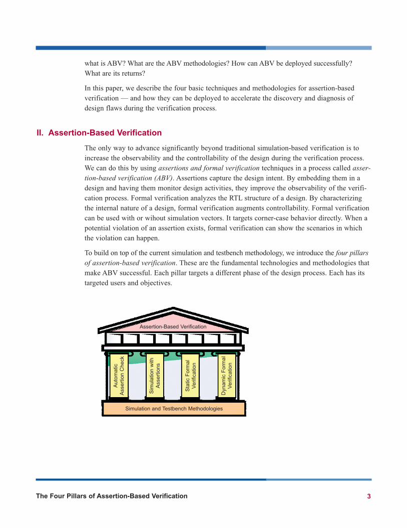
To build on top of the current simulation and testbench methodology, we introduce the four pillarsof assertion-based verification. These are the fundamental technologies and methodologies thatmake ABV successful. Each pillar targets a different phase of the design process. Each has itstargeted users and objectives.
The Four Pillars of Assertion-Based Verification 3
Assertion-Based Verification
Simulation and Testbench Methodologies
Aut
omat
ic
Ass
ertio
n C
heck
Sim
ulat
ion
with
Ass
ertio
ns
Dyn
amic
For
mal
Ver
ifica
tion
Sta
tic F
orm
alV
erifi
catio
n
III. Pillars of ABV
The four pillars of assertion-based verification are:
Pillar 1: Automatic Assertion Check
A set of pre-defined assertion rules is applied to the RTL code of the design to target commonnetlist problems and design flaws. Whereas the traditional lint tools analyze the syntax andsemantics of RTL code, automatic assertion check synthesizes the design and employs formalmethods to analyze the internal structures of the design. No input is required from users. Manycommon design flaws are detected quickly and easily with this methodology.
Pillar 2: Static Formal Verification
Designers add assertions to their code to capture design intent and to annotate their assump-tions. As they do so, they get immediate feedback with static formal verification. Exhaustiveformal verification analyzes the assertions in a design determining whether they are true, falseor indeterminate. This analysis is static, which means analysis starts from a single unique state.In many cases, the state after reset is used, so no testbench or simulation is required. However,the initial state can also be derived from simulation. Static formal verification is usually per-formed at the block level.
Pillar 3: Simulation with Assertions
User-specified assertions (and assertions promoted from automatic assertion checking) aresimulated with the design and the test environment. They passively monitor activities inside thedesign and on the interfaces to ensure the design is working correctly. Whenever an assertion isviolated, it is reported immediately. The problem need not be propagated to the output ports forit to be detected by the testbench. At the same time, the assertions collect coverage and statisticsinformation, which reflect how completely simulation exercises the functionality of the design.
Pillar 4: Dynamic Formal Verification
Formal verification analyzes the design’s assertions and determines whether each is true, false orindeterminate. Whereas static verification starts from a single state, dynamic formal verificationruns concurrently with simulation and leverages all simulation vectors. It identifies states “close”to the assertions and performs local formal analysis about them. Dynamic formal verificationtakes advantage of the design knowledge encapsulated in the simulation vectors to explore newbehaviors in the design — instead of simply duplicating activities already performed by simula-tion. Dynamic formal verification fills the gap between static formal verification and simulation.
4 The Four Pillars of Assertion-Based Verification
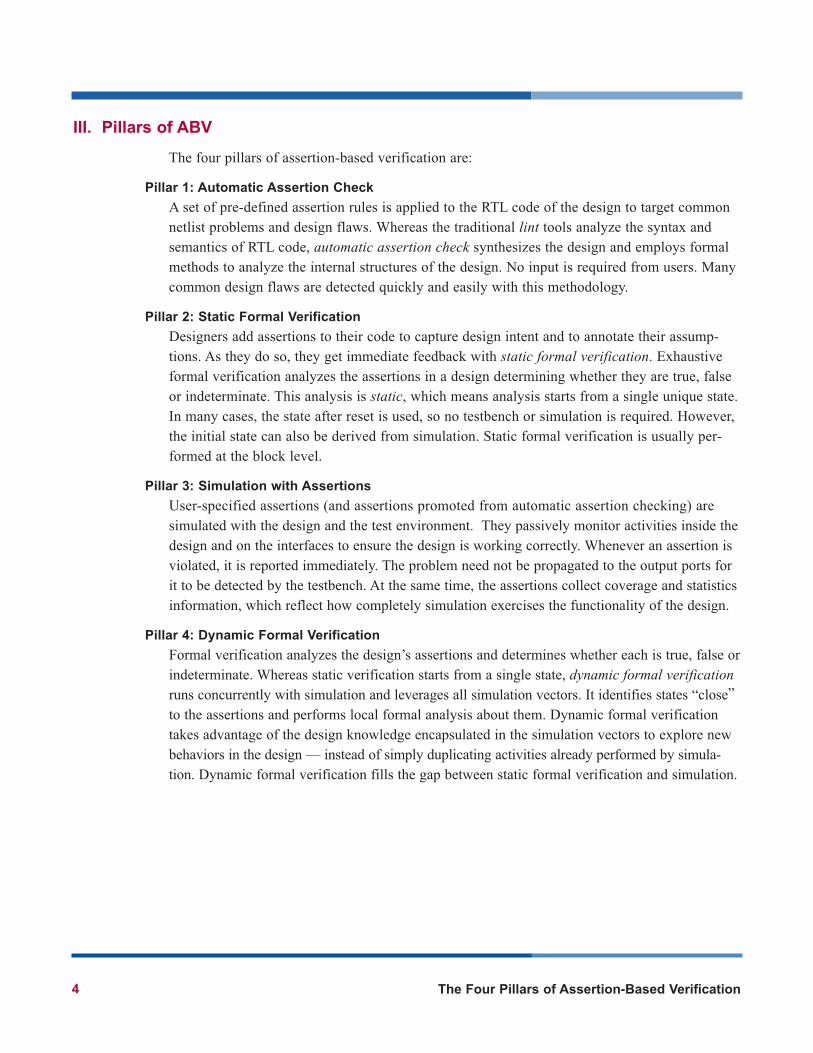
IV. ABV Processes
Assertion-based verification enables the design and verification team to work closely togetherthrough the following processes.
Design for Verification
With intimate design knowledge, designers can capture design intent and assumptions withassertions15. Embedded assertions capture design problems locally — well before bug scenariospropagate to the output ports. Leveraging existing regression environments provide betterobservability into the design. With assertions, hard-to-verify logic and critical-coverage pointsare identified. They help audit the quality of the testbenches and hence, identify holes in theregression environment.
Coverage-Driven Verification
Coverage-driven verification is a methodology for verification closure. It improves verificationenvironments with directed-random stimulus generation. But if the coverage metric is weak(such as code coverage alone) the verification specialist might get a false sense of security.One commonly-asked question is: “How good is the generated stimulus that tests the key func-tionality of the design?” To answer this question, it is important to augment the base coveragemetric with a measure of the coverage attained by the assertions (which represent the keyfunctionality of the design). Critical-coverage points, cause-and-effect implications, protocoltransaction coverage, and so on are good components of such an extended metric.
The Four Pillars of Assertion-Based Verification 5
High-level Specification
Verification Regression
Test Plan
Environment
Directed Tests
Design Spec
Architecture
Functional Blocks
Divide-and-Conquer Verification
After the chip architecture is defined, internal interfaces and on-chip buses are finalized. At thispoint, the testplan calls for the creation of interface protocol monitors. These monitors enableeach functional block to be verified individually, ensuring each does not violate its interfaceprotocol specification. These monitors can be leveraged as interface constraints, which are usedby static and dynamic formal verification to “harden” the functional blocks — which is espe-cially important for functional blocks that exhibit behavior hard to verify at the chip level.
Structural Verification
Simulation-based regression verifies end-to-end behavior well. However, many of today’sdesigns have implementation-specific structures that cannot be verified effectively withsimulation alone. One interesting example is the verification of asynchronous clock-domaincrossing (CDC) metastability effects. Simulating all the CDC signals to ensure a design has no metastability problems is difficult. Fortunately, structural netlist analysis can ensure allCDC signals are synchronized correctly.
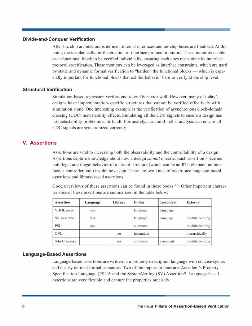
V. Assertions
Assertions are vital to increasing both the observability and the controllability of a design.Assertions capture knowledge about how a design should operate. Each assertion specifiesboth legal and illegal behavior of a circuit structure (which can be an RTL element, an inter-face, a controller, etc.) inside the design. There are two kinds of assertions: language-basedassertions and library-based assertions.
Good overviews of these assertions can be found in these books15,16. Other important charac-teristics of these assertions are summarized in the table below:
Language-Based Assertions
Language-based assertions are written in a property description language with concise syntaxand clearly defined formal semantics. Two of the important ones are: Accellera’s PropertySpecification Language (PSL)20 and the SystemVerilog (SV) Assertion21. Language-basedassertions are very flexible and capture the properties precisely.
Assertion Language Library In-line In-context External
VHDL assert yes language language
SV Assertion yes language language module binding
PSL yes comment module binding
OVL yes instantiate hierarchically
0-In Checkers yes comment comment module binding
6 The Four Pillars of Assertion-Based Verification
The assertion language, PSL, is design-language neutral; supports both VHDL and Verilog. It is well suited for capturing temporal properties. SystemVerilog Assertion can only be used withSystemVerilog code. However, users can leverage the procedural description of SystemVerilogto capture complex hardware structures. Complex assertions and protocol monitors can be builtwith both assertion languages — however, users must learn and master the language first.
Library-Based Assertions
Library-based assertions overcome the learning curve presented by language-based assertions.Library-based assertions capture commonly-used assertions in a library format. Several asser-tion libraries are available: Open Verification Library (OVL)22 from Accellera, SystemVerilogAssertion Library from Synopsys and the CheckerWare library from 0-In23.
The OVL library is the most basic with about 30 elements. Synopsys offers a SystemVerilogimplementation of the OVL library with additional elements and enhancements — it has roughly50 elements. The 0-In CheckerWare library is the most comprehensive with about 70 elements.It offers complex assertions that check many functional elements (such as scoreboard processes,data integrity cases, arbitration schemes and clock-domain crossing protocols). It is the onlylibrary that offers comprehensive coverage information with its assertions, which is essentialfor performing coverage-driven verification.
Example
This simple example illustrates the different assertion approaches. The same assertion isexpressed in English and in code.
Assertion in English:
The DMA buffer should not overflow.
(i.e., when it is full, write should not happen)
Assertion in Verilog:
//synopsys translate_off
always @(posedge dma_clk) begin
if (fifo_full && fifo_write)
$display("DMA buffer overflow at time %d",$time);
end
//synopsys translate_on
Assertion in VHDL:
process (dma_clk) begin
if dma_clk'event and dma_clk = '1' then
assert not (fifo_full and fifo_write)
report "DMA buffer overflow" severity FAILURE;
end if;
end process;
The Four Pillars of Assertion-Based Verification 7
Assertion in SystemVerilog:
property dma_buffer_overflow;
@(posedge dma_clk)
not (fifo_full && fifo_write);
endproperty
assert property (dma_buffer_overflow);
Assertion in PSL:
property dma_buffer_overflow =
never ( fifo_full and fifo_write) @ (posedge dma_clk);
assert dma_buffer_overflow;
OVL Assertion:
dma_buffer_overflow assert_fifo_index
#(4, 16) // severity level, depth
(dma_clk, dma_rst, push, pop);
CheckerWare Assertion:
/* 0in fifo –enq push –deq pop –depth 16 -severity 4
-name dma_buffer_overflow */
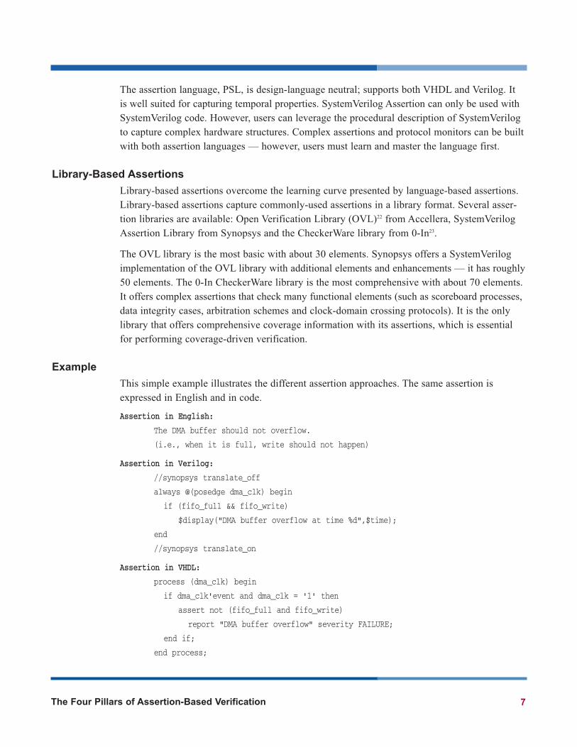
VI. Pillar 1: Automatic Assertion Check
Design for verification begins when RTL code is first created to implement the design ele-ments. For maximum value, designers should perform automatic assertion check as they aredeveloping the RTL code. Whereas the traditional lint tools analyze the syntax and semanticsof the design code, automatic assertion check synthesizes the design and employs formal meth-ods to analyze the internal structures. Many common design mistakes — such as combinationalfeedback loops, case semantics problems, synthesis-to-simulation mismatch problems and soon — can be found quickly with this methodology.
8 The Four Pillars of Assertion-Based Verification
AutomaticAssertion
Check
Some examples
Block-level checks:Arithmetic overflowClock used as dataCase semantic errorDeadlock stateUnreachable stateUnreachable blockIndex out of range
Chip-level checks:Bus contentCombinational feedback loopIncorrect clock-domain crossingMissing synchronizerMultiple driven netStuck at register
Structural analysis with pre-defined assertion rules
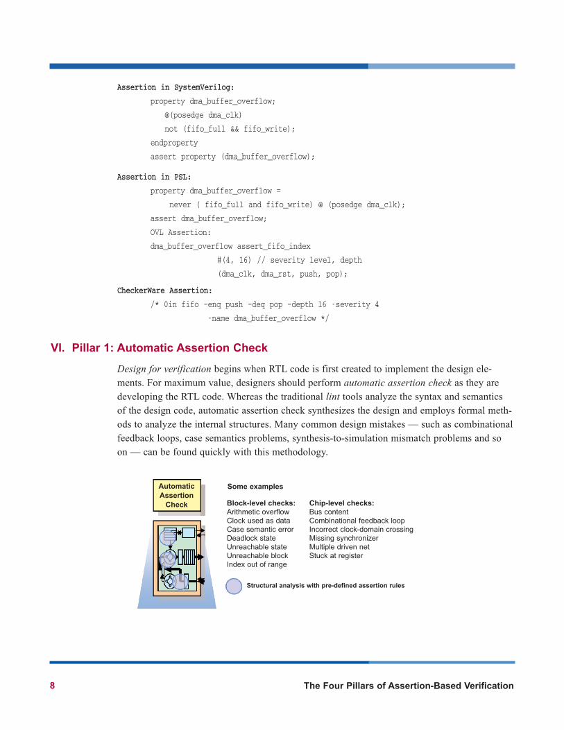
In addition, certain design structures — such as clock-domain synchronization structures, busstructures, finite state machines and so on — are difficult to verify with simulation alone.Automatic assertion check can recognize these structures. Sophisticated design rules12 arechecked without using simulation, which is typically complicated and can easily be overlookedby designers.
Common Issues Found
One common issue is design failure from asynchronous clock-domain crossing (CDC) problems.Automatic assertion check can identify the CDC signals in the design. It then checks for theabsence of synchronization flops, incorrect combinational logic in the CDC path, reconvergenceof CDC signals and so on. Besides automatic checks, assertions are generated for simulation.These promoted assertions ensure CDC signals are stable when they cross clock domains andthey are sampled correctly by the receiving registers13.
With coverage-based verification, the quality of the simulation suites is measured with respectto simulation coverage. However in the RTL code, unused logic, stuck-at logic, unreachableblocks and unreachable states distort the coverage metrics. Automatic assertion check identifiessuch dead code, so that RTL models can be augmented before they are checked in for functionalsimulation.
User Experience
One design team4 reported that normal lint tools were not able to check all forms of CDC vio-lations — especially reconvergence errors with CDC signals. Traditionally, such problems werefound occasionally with timing simulation on the gate-level netlist and tracking down the prob-lems took hours. With automatic assertion checks, reconvergence problems were detected earlyin the design cycle. The team readily located the offending logic, fixed the synchronization andre-ran CDC analysis to verify that the errors were fixed correctly.
Potential bus connection
Dead-end state Incorrect CDC crossing(due to combinational logic)
ST0 ST1
data_a
clock_a
sel_a sel_b
clock_a
data_b
clock_b
clock domain A clock domain B
ST2
logic
The Four Pillars of Assertion-Based Verification 9
Summary
Benefits:
• The assertion rules are pre-defined; the process is fully automated• Any violation represents a deviation from known good design practices
Best used for:
• Block level before the RTL code is checked in• Chip level after integration• Designs with multiple asynchronous clock domains
Not good for:
• Coding style and syntax checking (language-based lint tools are more suitable)
VII. Pillar 2: Static Formal Verification
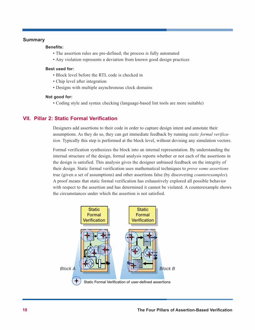
Designers add assertions to their code in order to capture design intent and annotate theirassumptions. As they do so, they can get immediate feedback by running static formal verifica-tion. Typically this step is performed at the block level, without devising any simulation vectors.
Formal verification synthesizes the block into an internal representation. By understanding theinternal structure of the design, formal analysis reports whether or not each of the assertions inthe design is satisfied. This analysis gives the designer unbiased feedback on the integrity oftheir design. Static formal verification uses mathematical techniques to prove some assertionstrue (given a set of assumptions) and other assertions false (by discovering counterexamples).A proof means that static formal verification has exhaustively explored all possible behaviorwith respect to the assertion and has determined it cannot be violated. A counterexample showsthe circumstances under which the assertion is not satisfied.
10 The Four Pillars of Assertion-Based Verification
Static Formal
Verification
Static Formal
Verification
Block A Block B
Static Formal Verification of user-defined assertions
The Four Pillars of Assertion-Based Verification 11
Each counterexample can be displayed in a waveform viewer. After understanding the circum-stances, the designer corrects the RTL code (or determines the counterexample represents anexceptional case not handled by the design). Using this methodology, a block can be verifiedsufficiently before it is integrated into the system-level simulation environment.
Common Issues Found
Based on our users’ experiences, the most common bugs found with this methodology are relatedto arbitration schemes, resource sharing, allocation and de-allocation of buses, interconnections,buffers and memories in the designs.
Complex control logic is involved. For instance, in a multi-layer AMBA architecture, there is onearbiter for each AHB bus, so exercising all possible combinations of request using simulation isinefficient. But, formal verification can verify exhaustively that the arbiter does perform the spec-ified arbitration scheme (by analyzing the internal structure of the design). Formal verification isthe right approach for this hot spot. In addition, once the arbiter is formally verified, the designteam no longer needs to worry about it in simulation. Alternatively, AMBA uses a central multi-plexer interconnection scheme. By this scheme, a central decoder controls the multiplexor —which selects the slave that is involved in the transfer. Only one bus master is communicatingwith one slave at any time. The logic involved in the AMBA interconnection scheme is not com-plex, however it is tedious to verify all possibilities one-by-one with simulation. By focusing onthe assertions, formal verification — especially static formal verification — can detect potentialsfor resource conflict. If one is found, formal verification shows a waveform of the involved sig-nals, such as HGrant, HSel and Haddress signals. In addition, formal verification ensures theaddress decoder and memory map will generate the correct HSel signals for the slaves.
User Experience
Several arbitration scheme violations were found in multiple projects11. In one project, the AHBbus arbiter implements a programmable priority arbitration scheme. However, the arbiter wasgiving the grant to a wrong request under a certain complex combination of corner-cases. Thebus master was granted when the slave was not ready. Hence, the grant was sometimes given toa different master first. When the original master requested again after the slave was ready, itwas not given the grant at the correct time.
In microprocessor designs, each one-hot multiplexer is usually implemented with pass transis-tors connecting separate input signals to a common output. Two-pass transistors must never beenabled at the same time; otherwise the resulting current could damage the chip. Since a singlemulti-million gate design can have tens of thousands of one-hot multiplexers, static formal ver-ification is the only viable solution. As a tape-out criterion, a company10 uses it to prove thatthe select lines for all the pass transistors are always mutually exclusive.
Summary
Benefits:
• Exhaustive formal analysis is performed on the concerned areas of the design• Verification can be done at the block level, independent of the simulation environment
Best used for:
• Arbiters, controllers, complex control logic and IP blocks• Potential areas of conflict, such as resource sharing, allocation and de-allocation of buses,
interconnections, buffers and memories in the design
Not good for:
• Interface logic (as constraints are required to define the legal inputs)• Structures with long latency, such as Ethernet MAC interface, elastic buffers, etc.
VIII. Pillar 3: Simulation with Assertions
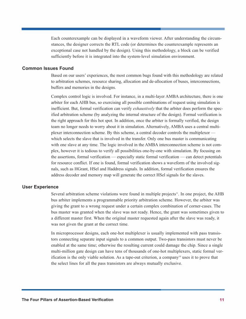
Assertion-based verification leverages the existing simulation environment. When running with functional simulation, assertions monitor activities inside the design and on the interfaces.Whenever an assertion is violated, it is reported immediately. The problem need not be propa-gated to the output ports for it to be detected by the testbench. Hence, assertions improve theobservability of the design. High degree of observability simplifies “bug triage” and allowsthe cause of any violation to be isolated easily.
The verification team creates directed tests based on a high-level specification of the design. In most cases, these tests do not stress the corner-cases and the critical structures of the designsufficiently. With assertions, designers can identify hard-to-verify logic and critical coveragepoints inside the design. During simulation, these assertions serve as coverage monitors: theycollect statistics and coverage information ensuring the concerned areas are well stimulated.They supply an important component of the metric for coverage-driven verification. To quoteone project manager: “Assertions provide a way for designers to tell their verification teamwhat they are worrying about and where potential logic problems are.”
12 The Four Pillars of Assertion-Based Verification
Simulation with Assertion Checkers
Stim
ulus
G
ener
atio
n
Res
pons
e C
heck
ing
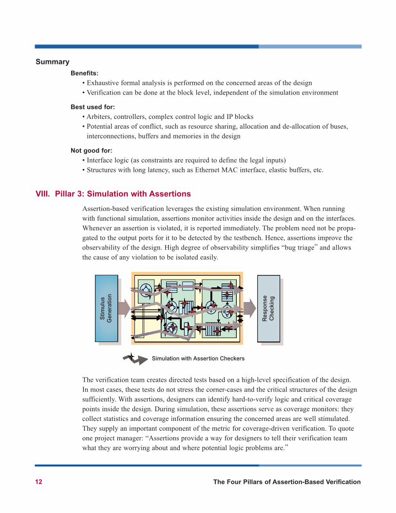
For example, an arbiter checker reports the number of requests and grants:• Arbiter checker coverage statistics
240:Requests and Grants120:Requests120:Grants
1:Fastest Grant Time (in cycles) 1:Slowest Grant Time (in cycles)1:Maximum Requests Outstanding0:Current Requests Outstanding2:Requests Asserted
00101:Requests Asserted Bitmap2:Grants Asserted
00101:Grants Asserted Bitmap
An AHB target protocol monitor reports the number of {read, write, busy, idle} transfers, theburst types and the number of {okay, error, retry, split} responses. • AHB target monitor coverage statistics
361:Total Transfers71:Read Transfers77:Write Transfers
213:IDLE Transfers0:BUSY Transfers
340:OKAY Responses20:ERROR Responses0:RETRY Responses0:SPLIT Responses
17:SINGLE Burst Type31:INCR Burst Type34:WRAP4 Burst Type18:INCR4 Burst Type0:WRAP8 Burst Type
16:INCR8 Burst Type0:WRAP16 Burst Type
32:INCR16 Burst Type90:Byte (8 Bits) Transfer Size18:Half Word (16 Bits) Transfer Size40:Word (32 Bits) Transfer Size
With this information, the verification team identifies “holes” in the test suites and audits the“completeness” of their regression environment.
The Four Pillars of Assertion-Based Verification 13
Common Issues Found
The most common issues found with this methodology are inter-module communication andinterfaces compliance problems. When design teams first integrate all the blocks for chip-levelsimulation, the blocks may fail to “talk” to each other. The main cause of these problems is:designers understand the interface specifications differently from the verification team. Evenwhen the specification is understood correctly, assumptions made by each designer might con-tradict each other. However, when the interface specification is captured with assertions, theybecome an executable reference. When used with simulation, they pinpoint modules that causeany protocol violation.
Alternatively, designs with standard interfaces such as AMBA, PCI-Express, Hyper Transport,DDR SDRAM, etc. can leverage the standard protocol monitors already available from thevendors, such a17. A well-designed protocol monitor also enables users to perform end-to-endverification. In a bus bridge design, with coverage and statistics information from the protocolmonitors, we can ensure the number of transactions received equals the number of transactionssent, at both sides of the bridge.
User Experience
Several companies have published their successes using assertions with the coverage-drivenverification methodology5,6,8. In general, directed tests are suited for functional verification, butthey often miss corner-case bugs due to complex combinations of events. As presented in thesepapers, project teams are moving from directed tests to directed random and fully random veri-fication environments5. High-level verification languages such as Verisity’s e18 or Synopsys’sVera19 are used.
But, randomly-generated stimulus presents two shortcomings:
• Stimulus might inadvertently focus on one part of the design while overlooking another• A simple mistake in the stimulus generator code can create a huge amount of useless stimulus
(which does not help the coverage goals at all)
To uncover such potential problems, RTL code coverage traditionally was used to provide qualityfeedback on the stimulus. Although code coverage is a good base-line measure, it is not sufficient.Assertions that identify critical coverage points buried deep inside the design provide the best indi-cators. In5, assertions are used as functional coverage monitors. In6, coverage information fromassertions is used to create a reactive testbench. In8, assertions are used to audit and fine-tune thestimulus generation process.
Summary
Benefits:
• Technology integrates seamlessly with the current simulation environment• Simulation is made more productive with improved observability
14 The Four Pillars of Assertion-Based Verification
Best used for:
• Standard interfaces, on-chip buses and well-defined interfaces in the design• Deeply buried hard-to-reach logic to ensure sufficient testing is performed• Critical coverage points to guide verification or directed random environments
Not good for:
• Code coverage and state machine coverage (coverage tools integrated with the simulators provide this information with much lower performance overhead)
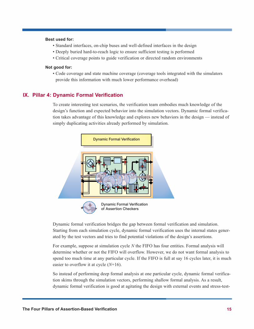
IX. Pillar 4: Dynamic Formal Verification
To create interesting test scenarios, the verification team embodies much knowledge of thedesign’s function and expected behavior into the simulation vectors. Dynamic formal verifica-tion takes advantage of this knowledge and explores new behaviors in the design — instead ofsimply duplicating activities already performed by simulation.
Dynamic formal verification bridges the gap between formal verification and simulation.Starting from each simulation cycle, dynamic formal verification uses the internal states gener-ated by the test vectors and tries to find potential violations of the design’s assertions.
For example, suppose at simulation cycle N the FIFO has four entities. Formal analysis willdetermine whether or not the FIFO will overflow. However, we do not want formal analysis tospend too much time at any particular cycle. If the FIFO is full at say 16 cycles later, it is mucheasier to overflow it at cycle (N+16).
So instead of performing deep formal analysis at one particular cycle, dynamic formal verifica-tion skims through the simulation vectors, performing shallow formal analysis. As a result,dynamic formal verification is good at agitating the design with external events and stress-test-
The Four Pillars of Assertion-Based Verification 15
Dynamic Formal Verification
Dynamic Formal Verificationof Assertion Checkers
ing corner-case behaviors. The process is like introducing randomly-timed stimuli7 with deter-ministic guidance from formal analysis. If a violation is discovered, formal analysis provides acounterexample to the assertion. Since stimulation stimulus is leveraged to find the violation,the counterexample is part simulation stimulus and part formal stimulus. Although dynamicformal verification is not completely exhaustive, it can handle large designs (i.e. at the chip-level). In addition, by providing the corresponding simulation vectors, users can guide or focusformal analysis on specific concerned areas in their designs.
This methodology has been used extensively to find corner-case bugs that are too deep or com-plex to reach with static formal verification. Most of the issues found with dynamic formal ver-ification require a long setup time in simulation. For example, when a linked list manager isclose to filling up all the storage space, back pressure should be generated. However, supposethe manager is late in asserting the back pressure signal. The next incoming packet will be cor-rupted when the manager tries to store it. It is impossible for formal verification alone to gener-ate thousands of packets to fill up the packet memory. However, dynamic formal verificationleverages what simulation has already done and amplifies the test.
Common Issues Found
Dynamic formal verification has been used extensively to verify bus bridge designs (such asAHB to AHB, AHB to PCI, PCI-Express to PCI-X, and numerous standards to propriety inter-nal buses). It is impossible to simulate all combinations of incoming and outgoing transactionswith the full range of timing parameters. Normally, functional simulation has verified thegeneric read and write transactions extensively. However, for the abnormal transactions such asabort, and retry, we have seen numerous cases where the bus bridge has failed to function prop-erly. As a result, the transaction was lost forever.
Dynamic formal verification fills this gap. By leveraging the transactions already performed by simulation and by understanding the control logic inside the bus bridge, formal verificationensures the bus bridge “understands” all incoming transactions correctly. The tool checks thedesign to determine whether there is any possibility that a transaction will not be transferredcorrectly from one interface to another.
On several occasions, we have noticed insufficient stress testing is done at the transaction level.For instance:
• The AMBA specification states that an ERROR response requires at least two cycles. Whenexamining the ERROR responses in simulation, we noticed that only 2-cycle error responseswere being performed. As a result, we do not know whether the bus master could handle errorresponses that take longer than two cycles.
• In a verification environment with a PCI-Express interface, we noticed that considerableeffort was spent building a directed random stimulus generator at the high level. Interestingly,it assumed that the link initialization and training process is always performed flawlessly.
16 The Four Pillars of Assertion-Based Verification
User Experience
Many design teams use dynamic formal verification to verify the correctness of bus interfacesand implementation. With the availability of standard protocol monitors17, this can be set upand done fairly seamlessly. Some of these successes have already been documented in pubicforums.
In one case, dynamic formal verification was used to verify a DMA controller, which is noteasy to verify exhaustively. DMA channels are allocated/de-allocated dynamically and datatransfers are interleaved among channels. Formal verification found a rare situation where datain memory is corrupted. The problem occurred when more than one channel finishes theirtransfers at the same time. During the de-allocation process, one channel’s address pointer isde-allocated twice and the other channel’s pointer is not de-allocated at all. As a result, whenthe same channel is allocated again, corrupted data is transferred. In this design, DMA channelswill never be allocated together because their access is controlled by an arbiter. However, mul-tiple channels can finish data transfer at the same time. The designer did capture this corner-case with an assertion. However, it was so difficult to make this happen in simulation that theassertion was never exercised.
In another project, dynamic formal verification was used to verify an Ethernet MAC interface4.Control logic in the design should control the processing elements so that they have fair andnon-conflicting access to a pool of resources. However, formal analysis uncovered a legal sce-nario under which certain resources were granted in an incorrect order. When the access orderis wrong, the memory system could be corrupted and the system could hang. This examplehighlights the power of dynamic formal verification — an Ethernet frame is over 1000 cycleslong. It is inefficient for static formal verification to drive a frame into the design. However,dynamic formal verification can take advantage of what simulation has done already.
Summary
Benefits:
• Dynamic formal verification leverages and amplifies the activities covered by normal simula-tion runs
• By understanding the design, formal analysis finds ways to explore some hard-to-reach cornercases
• Late stage bugs were found with this methodology before tape-out
Best used for:
• Control logic for standard interfaces, on-chip bus interfaces, memory interfaces, etc.• Designs with long latency such as: Ethernet MAC, DMA controllers, memory controllers,
bus bridges, etc.• Designs with serial interfaces, such as PCI-Express, SAS, etc.
Not good for:
• Datapath and algorithmic verification
The Four Pillars of Assertion-Based Verification 17
X. Conclusion
Assertion-based verification is a shift in verification methodology. Traditional functional verifi-cation tries to stimulate the design and observe the responses from the outside. As today’sdevices become more complex, multi-functional and integrated, observability and controllabili-ty are so low that pseudo-random simulation can no longer exercise the internals of the devicesufficiently. ABV technologies and methodologies are hence developed to zero in to the struc-ture of the design.
As a result, the responsibility of verification is also shifting from over-the-wall verificationteam to involve designers as well. Design knowledge becomes a critical criterion for successfulfunctional verification. With assertions, we can detect bugs sooner; with formal verification, wehave more direct control of the verification effort.
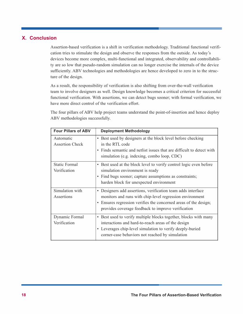
The four pillars of ABV help project teams understand the point-of-insertion and hence deployABV methodologies successfully.
Four Pillars of ABV Deployment Methodology
Automatic Assertion Check
• Best used by designers at the block level before checking in the RTL code
• Finds semantic and netlist issues that are difficult to detect with simulation (e.g. indexing, combo loop, CDC)
Static Formal Verification
• Best used at the block level to verify control logic even before simulation environment is ready
• Find bugs sooner; capture assumptions as constraints; harden block for unexpected environment
Simulation withAssertions
• Designers add assertions, verification team adds interface monitors and runs with chip-level regression environment
• Ensures regression verifies the concerned areas of the design; provides coverage feedback to improve verification
Dynamic FormalVerification
• Best used to verify multiple blocks together, blocks with many interactions and hard-to-reach areas of the design
• Leverages chip-level simulation to verify deeply-buried corner-case behaviors not reached by simulation
18 The Four Pillars of Assertion-Based Verification
References
1. Verification Strategies for Integrating 3G Baseband SoC, Yves Mathys, Motorola SPS, DAC 2003.
2. High Level Formal Verification of Next-Generation Microprocessors, Tom Schubert, Intel, DAC 2003.
3. Core-based ASIC at Samsung, Chang Hyun Cho, Samsung Electronics, Keynote Speech, The 2002
International Technical Conference on Circuits/Systems, Computers and Communications.
4. Assertions Enter the Verification Arena, Frank Dresig, Alexander Krebs, Falk Tischer, Dresden Design
Center of AMD, Chip Design Magazine, Dec 2004.
5. Coverage and Assertion-Based Verification Coverage Based DV from Testplan to Tapeout using Random
Generation and RTL Assertions, Carey Kloss, Dean Chao, Cisco Systems, DVCon 2004.
6. An Efficient Reactive Testbench with Bug Identification Structure, Namdo Kim, Byeong Min, Samsung
Electronics, DVCon 2004.
7. Audit Your Design to Assess and Even Reduce the Amount of Random Testing Needed, Dan Joyce, Ray
Harlan, Ramon Enriquez, DVCon 2003.
8. 0-In ABV Success Cases, Mr.Masami Iwamoto, Fujitsu LSI Technology, EDA TechnoFair 2003.
9. DVCon’04 Trip Report, John Cooley, www.deepchip.com/posts/dvcon04.html
10. Sun System News, Vol 71, Jan 5, 2004, sun.systemnews.com/articles/71/1/hw/11871
11. Assertion-based Verification for ARM-based SoC Design, Ping Yeung, DesignCon East, 2004.
12. Synthesis and Scripting Techniques for Designing Multi-asynchronous Clock Designs, Clifford
Cummings, Synopsys Users Group Conference, San Jose 2001.
13. Using Assertion-based Verification to Verify Clock Domain Crossing Signals, Chris Kwok, Vijay Gupta
and Tai Ly, DVCon 2003.
14. Deep Formal Verification Powers Assertions, Curtis Widdoes and Richard Ho, EEDesign, 18 April, 2002.
15. Assertion-based Design, Harry Foster, Adam Krolnik, David Lacey, Kluwer Academic Publishers, 2003.
16. Using PSL/Sugar with HDL for Formal and Dynamic Verification 2nd Edition, Ben Cohen, Srinivasan
Venkataramanan and Ajeetha Kumari, VhdlCohen Publishing.
17. CheckerWare Monitors, 0-In website: www.0in.com/products_monitors.html
18. Specman Elite, Verisity website: www.verisity.com/products/specman.html
19. VERA Tool, Synopsys website: www.synopsys.com/products/vera/vera.html
20. Property Specification Language (PSL), Accellera, www.eda.org/vfv
21. SystemVerilog, Accellera, www.eda.org/sv
22. Open Verification Library (OVL), Accellera, www.eda.org/ovl
23. Assertion-based Verification V2.2 User Guides, 0-In Design Automation, 2004.
The Four Pillars of Assertion-Based Verification 19

Corporate HeadquartersMentor Graphics Corporation8005 S.W. Boeckman RoadWilsonville, Oregon 97070USAPhone: 503-685-7000North American Support CenterPhone: 800-547-4303Fax: 800-684-1795
Pacific Rim Mentor Graphics TaiwanRoom 1603, 16F, International Trade BuildingNo. 333, Section 1, Keelung RoadTaipei, Taiwan, ROCPhone: 886-2-27576020Fax: 886-2-27576027
Europe Mentor Graphics Deutschland GmbHArnulfstrasse 20180634 MunichGermanyPhone: +49.89.57096.0Fax: +49.89.57096.400
Silicon ValleyMentor Graphics Corporation1001 Ridder Park DriveSan Jose, California 95131 USAPhone: 408-436-1500Fax: 408-436-1501
Japan Mentor Graphics Japan Co., Ltd.Gotenyama Hills7-35, Kita-Shinagawa 4-chomeShinagawa-Ku, Tokyo 140 JapanPhone: 81-3-5488-3030Fax: 81-3-5488-3031
For more information, call us or visit: www.mentor.com
Copyright © 2004 Mentor Graphics Corporation. This document contains information that is proprietary to Mentor Graphics Corporation and may be duplicated in whole or in part by the original recipient for internal business purposed only, provided that this entire notice appears in all copies. In accepting this document, the recipient agrees to make every reasonable effort to prevent the unauthorized use of this information. Mentor Graphics is a registered trademark of Mentor Graphics Corporation. All other trademarks are the property of their respective owners.
C&A 11-04 TECH6490-w


![ASSERTION REASON QUESTIONS - gateguru.org · ASSERTION REASON QUESTIONS Q1. Determine the correctness or otherwise of the following Assertion [a] and the Reason [r] Assertion: The](https://img.pdfslide.net/doc/110x75/5ace747d7f8b9ae2138b5d9a/assertion-reason-questions-reason-questions-q1-determine-the-correctness-or-otherwise.jpg)