Embed Size (px)
Citation preview

The Future of Homecare Lifting is Here!
HYDRAULIC OR BATTERY OPERATED
MODEL:400H / 400EL / 400LK

Thank you for choosing the BestLift 400
To better serve you, please record the following information:
Dealer Name:
Telephone:
Serial #:
Date of Purchase:
INSPECT YOUR MERCHANDISE
Upon receipt of your Bestcare Lift, verify that all merchandise is complete
and free from any shipping damage. Refuse delivery if the packaging
appears to be badly damaged. If the merchandise is received damaged or
is missing components, contact the shipping company immediately and file
a claim.
For further assistance, contact your local dealer or Bestcare at the
following:
Bestcare LLC
2920 Pacific Drive
Norcross, GA 30071
tel 678-679-6690 / free 1-877-822-9033 / fax 678-679-6697
www.bestcarellc.com
© 2012 Bestcare LLC

The BestLift Series of full body patient lifts reflect innovative state of
the art design to increase user mobility. Your BestLift patient lift will
provide years of service if it is properly maintained as any piece of
electric/mechanical equipment requires.
Pay careful attention to the following important information regarding
the care, maintenance, and operation of the patient lift. Carefully read
these instructions before assembling the lift, or attempting to lift a
user with the device.
Always keep the Owner’s Manual available with the lift.
DEFINITIONS & SYMBOLS
In this manual the user refers to the patient or resident and may be used
interchangeably at different times. Caregiver refers to the operator or
person who is assisting with the transfer.
Symbols used in this manual and their meanings:
Warning! Failure to heed this warning may result in damage to
the product or serious injury to the operator and/or user.
Important instructions! Read and understand the instructions
in the manual before using the product.
Note! Important information concerning the product and/or its
safe and correct usage follows.
SAFETY INSTRUCTIONS

MAXIMUM Weight Capacity: 400 pounds
NEVER exceed the maximum lifting capacity indicated on the patient
lift or any accessory used in conjunction with the lifter.
Take special care with users that cannot provide assistance while
being lifted. I.e. patients who are comatose, spastic, agitated, or
otherwise severely handicapped.
DO NOT attempt to lift and transfer a user without their nurse or
doctor’s prior approval.
DO NOT place any objects between the sling and the user. I.e.
cushion padding, etc.
DO NOT use slings that are not specifically designed tested or
approved for use on Bestcare patient lifts.
DO NOT lock caster brakes during lifting.
Close the base before moving the patient lift.
ALWAYS keep the suspended user centered between the base legs.
DO NOT attempt to roll the lift and casters over floor obstacles when
in use.
DO NOT use patient lift for transportation.
NEVER interfere with a lift and transfer in process unless instructed
to do so.
NEVER leave the user unattended during lifting.
DO NOT attempt to repair or replace parts and components that are
not designed, tested or approved for use on Bestcare patient lifts.
Before attempting to lift anyone, please practice operating the lift. Prior to
the actual lift and transfer procedure, read and study the instructions for
proper and safe operation of the patient lift. Be able to explain the entire
lifting procedure to the user as well as answer any questions they may
have concerning the procedure.
WARNING!
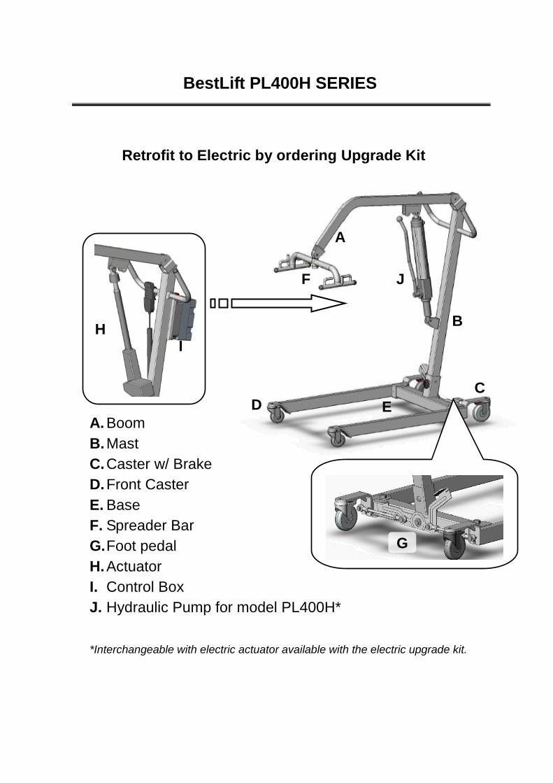
BestLift PL400H SERIES
A. Boom
B. Mast
C. Caster w/ Brake
D. Front Caster
E. Base
F. Spreader Bar
G. Foot pedal
H. Actuator
I. Control Box
J. Hydraulic Pump for model PL400H*
*Interchangeable with electric actuator available with the electric upgrade kit.
Retrofit to Electric by ordering Upgrade Kit
J
H I
A
B
C D E
F
G

BestLift PL400H OVERVIEW
1. Carefully unpack box saving box and packaging.
2. Follow owner’s manual for assembly and use of BestLift 400H.
3. Lock wheels to keep Base stationary.
4. Slide Mast into square sleeve located at rear and center of Base.
5. Fasten the Mast to the Base with the Bolt, Washer, and Black Hand Nut
provided. Tighten and secure the Mast by hand.
6. Fasten Boom to Mast using the Bolt, Washer, and Black Hand Nut
provided. Tighten and secure the Mast by hand.
7. Attach Spreader Bar to Boom with Keeper Pin and key ring provided.
8. Attach bottom Hydraulic piston rod to the Mast with Keeper Pin and key
ring then attach top Hydraulic piston rod to the Boom in the same
fashion. See picture below.

BestLift PL400EL OVERVIEW
1. Carefully unpack box saving box and packaging.
2. Follow owner’s manual for assembly and use of BestLift PL400EL.
3. Lock wheels to keep Base stationary.
4. Slide Mast into square sleeve located at rear and center of Base.
5. Fasten the Mast to the Base with the Bolt, Washer, and Black Hand Nut
provided. Tighten and secure the Mast by hand.
6. Fasten Boom to Mast using the Bolt, Washer, and Black Hand Nut
provided. Tighten and secure the Boom by hand.
7. Attach Spreader Bar to Boom with Keeper Pin and key ring provided.
8. Attach Electric Actuator bottom end to the Mast with Keeper Pin and key
ring then attach Electric Actuator top end to the Boom in the same
fashion. See picture below.
9. Hang Control Box on Lift Handle Bars and plug in the Electric Actuator,
Hand Control and Charger
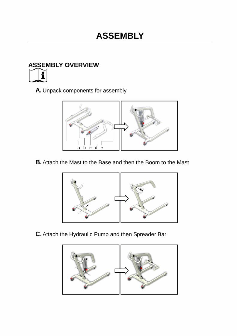
ASSEMBLY
ASSEMBLY OVERVIEW
A. Unpack components for assembly
B. Attach the Mast to the Base and then the Boom to the Mast
C. Attach the Hydraulic Pump and then Spreader Bar
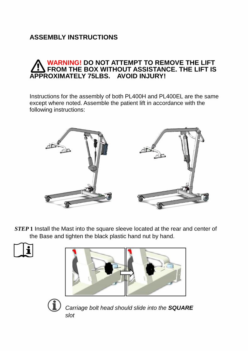
ASSEMBLY INSTRUCTIONS
WARNING! DO NOT ATTEMPT TO REMOVE THE LIFT FROM THE BOX WITHOUT ASSISTANCE. THE LIFT IS
APPROXIMATELY 75LBS. AVOID INJURY! Instructions for the assembly of both PL400H and PL400EL are the same except where noted. Assemble the patient lift in accordance with the following instructions:
STEP 1 Install the Mast into the square sleeve located at the rear and center of
the Base and tighten the black plastic hand nut by hand.
Carriage bolt head should slide into the SQUARE
slot

STEP 2 Install the boom between the brackets at the top of the Mast. Fasten with
hex bolt, washer and black plastic hand nut.
Hex Bolt head goes on the side with
the small lock screw pre-installed.
STEP 3 Install spreader at the end of the Boom and secure it in place with steel
pin and key ring.
Secure Spreader Bar to Boom with steel pin and key ring
The BestLift PL400H Series of patient lifts comes in either the manual
hydraulic operation PL400H or the PL400EL battery powered operation. If
you have purchased the PL400H, you can upgrade to a battery powered lift
by simply contacting your dealer or Bestcare to order the Electric Upgrade
Kit.
The BestLift patient lift is ready to use as soon as the Hydraulic Pump or
Electric Actuator is installed and the connections between the Base & Mast,
Mast & Boom, and Boom & Spreader bar are secured. No tools are
necessary to assemble the lift and can be accomplished with the supplied
hardware. If you have any questions contact your dealer or Bestcare.

STEP 4 Installation of Hydraulic Pump or Electric Actuator
A. Attach bottom piston of either the Hydraulic Pump or Actuator by
sliding it between the Mast brackets. Secure with steel pin and key ring.
Both Cylinder and Actuator attach to
the SAME bottom bracket
B. Attach the top end of the of the Hydraulic pump or Actuator between
the Boom bracket and secure with steel pin and key ring
The top end of the Hydraulic Cylinder must be attached to the Boom
bracket slots nearest the Mast. The Actuator must be attached to the
Boom bracket farthest away from the Mast. This is indicated by the
label next to the Boom bracket.

i. Hydraulic Cylinder shall be installed at position: a
ii. The Electric Actuator shall be installed at position: b
Incorrect installation may result in damage to the equipment or
pose a safety risk.
After installing the Hydraulic Cylinder, the assembly of the Hydraulic
powered lift is complete. The following assembly instructions apply
to PL400EL and Electric Upgrade Kit users only.
The Genesis 400 Series Lift operates
either in a Hydraulic or an Electric
mode. The picture to the left shows a
Hydraulic Cylinder and the one to the
right an Electric Actuator

STEP 5 Install the Control Box and Hand Control. These instructions apply to
PL400EL and Electric Upgrade Kit owners ONLY.
A. Attach the Control Box hangers to the Control Box
B. Hang the control box by the hangers on the handlebars of the lift.
C. Insert the Hand Control plug into the second port from the top.
D. Insert the Actuator Plug into the third port from the top
The Actuator plug must be inserted all the way in until the Black
O-ring is no longer visible or else the Actuator will not function.
The first port is used for the Charger and the remaining ports are unused.
DIAGRAM OF CONTROL BOX
Actuator Plug-in

MAINTENANCE & INSPECTION CHECKING LIST
The operator of the lift is to inspect the BestLift 400 Series Bestcare Lift
before each use. Check all bolts for tightness. Make sure the base can be
easily widened, and that all lift parts are in place. Make sure all casters turn
freely, and that the caster brakes can be engaged. Make certain all
necessary items (i.e. slings, wheel chairs, etc.) are accessible and ready
for use. Check No Tool Hand Nuts also. At least once a month, the lift
should be thoroughly inspected by a person qualified to recognize any
signs of wear, and looseness of bolts or parts. Replace any worn parts
immediately. To lubricate, place a drop of oil on the following points: Top
of Mast, Spreader Hinge, and Caster Axles when the PL400H or PL400EL
is assembled and every month thereafter.
Checking The Battery
1. Check batteries by pressing the Battery Testing Button (blue
circle with a battery sign) on the control box.
2. Batteries are fully charged when all lights on the Battery Indicator
are “ON".
3. Charge batteries when Indicator shown only one “GREEN” light.
4. Do not use the lift when no “GREEN” light is shown. Charge the
batteries immediately.
5. Replace batteries when frequent charging is needed.
Know What The Battery Indicator Lights Are Telling You:
RED AMBER GREEN GREEN GREEN NOTE
ON ON ON ON ON FULLY CHARGED
ON ON ON OFF OFF NEED CHARGE
ON ON /
O FF
OFF OFF OFF CHARGE IMMEDIATELY. DON'T USE THE LIFT
OFF OFF OFF OFF OFF BAD BATTERIES OR BAD CONNECTION

Warning Buzzers
The control box has a buzzer that provides you with information on the
status of the batteries and the lift. To stop the buzzer, push down the
RESET button or press the Battery Indicator.
BUZZER TYPE INDICATION NOTE
2 beeps/sec Low Battery (red/amber lights on)
Charge batteries immediately.
3 beeps/sec Low Battery (red light on)
Charge batteries immediately.
6 beeps/sec Very Low Battery (no light on)
Charge batteries immediately.
3 beeps every other second
Bad Battery (no light on)
Replace batteries.
3 long beeps Overloaded. Batteries are charged but lift does not lift.
Exceeded maximum load capacity.
Charging The Batteries
1. Ensure the power is switched "ON" (the red “RESET” button
should be up).
2. Insert charging plug into charging port on the control box.
3. Plug charger to power supply.
4. All lights of battery indicator should be "ON" while charging.
5. It takes approximately 2-3 hours to fully charge the batteries from
one green light.
6. It takes approximately 7-9 hours to fully charge the batteries from the
red light.
7. Do not leave the batteries on charging for an extensive period of
time. This will shorten the life of the batteries.
8. Do not let the batteries run down to the last red light. This might
shorten the life of the batteries or damage the batteries.
9. Unplug the charger first before using the lift.
Important Notes On Charging
Push lift to charging location and charge the batteries with the charger
provided. Avoid unplug hand control and motor from control box.
Frequent plug/unplug of the hand control and motor into/from the control

box may damage the control box.
Do not charge batteries over 12 hours.
OPERATING INSTRUCTIONS NOTE: Turn the lift “ON” by turning the red “RESET” button clockwise. Turn
the lift “OFF” by pressing down the “RESET” button.
MAINTENANCE SCHEDULE
Item In the
Beginning Monthly
Every 3
months
Boom & Spreader Bar:
Check connections between
1) Boom and Spreader Bar and
2) Boom and Mast for improper connection,
looseness, or wear.
3) Check the Boom for bending and deflection.
●
●
●
●
Mast:
4) Check the Mast for bending or deflection.
5) Check the steering bar for damage or loose
screws.
●
●
●
●
Base & Foot Peddle:
6) Check bolts and nuts for looseness.
7) Check casters and axle bolts for tightness.
8) Check rubber parts on the casters for deflection.
9) Apply grease to caster ball bearings if needed.
●
●
●
●
●
●
●
Cleaning:
10) As needed.
●
Actuator & Control Box:
11) Make sure the control box is firmly affixed to the
mast.
12) Make sure the pins are firmly affixed the actuator to
the Boom and the Mast.
13) Make sure the connecting cable of the actuator
and the control box is not loose.
14) Make sure the Battery Indicator has least 2 green
LED lights illuminated prior to use.
●
●
●
●
●
●
●
●
Slings & Sling Hardware:
15) Check sling for wear.
16) Check sling hardware every time before use.
●
●
●
●

Transfer From Bed
Roll user onto the opposite side and position him/her on the flat section of
the sling. This will allow you to unroll the remainder of the sling from the
other side of the user.
Once the sling has been positioned centrally, feed the leg sections under
the thighs and draw them up between the thighs.
Should Raise and Lower the head of the bed if this function is available.
Move the lift slowly towards the user and position the spreader bar over the
user's/patient's chest.
Attach Loops to Spreader Bar: Notice Loops on sling attach to Spreader
Bar Hooks A & C and B & D as illustrated below. The Bottom two Loops E
and F are connected to opposite Hooks on the Spreader Bar after passing
one Loop through the other.
Note: Reverse the above procedures when returning the user/patient to
bed
Lift the user above the bed by using the Hand Control or Hydraulic
pump handle. (Wheels unlocked & base spread wide while lifting, foot
pedals control base width)
Pull lift away from bed. Position user over the wheelchair or chair then
lower the patient onto the surface. (Widen base for access to wheel
chair)
Note: Reverse the above procedures when returning the user/patient to
bed. There must always be at least one caregiver present when lift is in
use.
XF
F
E
E
A B C
D
E
F
A B
C D
E F
Loops Cross Over & through each other

Transfer From Wheelchair
Grasp the sling at each corner of the "U" shape of the commode
aperture. (Sani Sling)
The sling should be fitted with the handle on the back section facing
outward.
Help the user lean forward slightly, then slide the sling down between
the chair and the user's back.
Position the commode aperture where the buttocks meet the seat.
Position the sling equally around both sides of the body.
Draw the leg sections to the front along the length of the user's thigh.
Check the sling's central positioning by comparing the lengths of the
leg sections when they are drawn forward.
Reposition the sling if the leg sections are not equal in length.
Feed the leg sections under the thighs.
From between the legs, gently pull the leg section up the inner thigh.
Feed as much material as possible under and between the thighs.
Ensure the leg sections are positioned midway under the thighs to
provide good support and greater comfort.
Move the lift slowly towards the user and position the spreader bar
over the user's chest.
Attach Loop a of sling to Hook A on Spreader Bar; attach Loop B to
Hook B; attach Loop C to Hook C; attach Loop D to Hook D. (See
example on page 15)
Lift patient above the wheelchair by using the Hand Control.
Pull lift away from wheelchair. Position patient over bed and lower
patient onto it. Always close base before transferring patient. Foot
pedals control base width.
Note: Reverse the above procedures when returning the user/patient
to a wheelchair.

Troubleshooting Guide
The following list of encountered problems and solutions will assist you in
determining what may be causing your Bestcare lift not to function as designed.
If you have a problem occurring that is not listed below please contact your
dealer or Bestcare technical support for help. Do not attempt to repair
components or parts on your lift as this may invalidate your warranty or cause
further problems that may result in patient injury. Stop using your lift
immediately if it is not functioning correctly or any warning beeps are heard.
I need to re-charge my batteries often or they fail to hold a charge when I
charge them
Replace the 2 internal batteries as they are at the end of their life cycle
Batteries should be changed every 18-24 months depending on usage
When I plug my charger into the control box I see no lights on the battery
indicator
Check to make sure the red re-set button is in the up position
Check to make sure the charger is firmly in the control box and plugged
into a wall socket
Replace your charger as it is at the end of its life cycle
If your charger is transmitting current then you need to replace your PCB
board in the control box
My actuator makes a clicking sound when I attempt to use my lift
Check to make sure the actuator plug is pushed into the control box so the
O Ring is not visible
Your actuator needs to be replaced as it is at the end of its life cycle
Your PCB board in the control box may be malfunctioning
The actuator will either go up or down but not both
Replace your hand control as it is at the end of its life cycle
Your PCB board in the control box may be malfunctioning
There is a grinding sound inside the actuator when lifting
Replace your actuator as the internal gears are stripped
The actuator stops and starts while lifting or lowering
Replace your batteries as they are at the end of their life cycle

My lift will not operate even though it shows the batteries are charged
Disconnect your charger from the control box as the lift will not work when
the charger is attached
Check to make sure the hand control is properly inserted to control box
Check to make sure your actuator is properly connected to the control box
Your hand control needs to be replaced as it is at the end of its life cycle
My lift will not operate and battery indicator has no lights illuminated
Check to make sure the red re-set button is in the up position
The internal batteries may not be connected together properly with the
connection wires
Batteries will no longer hold a charge and must be replaced
Your PCB board is damaged and must be replaced
When lifting I hear 3 long beeps from the control box
You are attempting to lift someone heavier than the safe working load
Stop the lift and lower safely to bed or chair immediately
When lifting I hear short beeping sounds from the control box
Charge the batteries
Replace the batteries if they fail to hold a charge
Hydraulic Pump Troubleshooting
Hydraulic Pump won't lift Boom:
Turn Release Knob counter-clockwise fully until it stops. Pump handle 5 times. Tighten
the valve. The Hydraulic pump
should now rise or lower.
Air is trapped in Hydraulic Cylinder:
Turn Release Bolt on top counter-clockwise.
Let pump return to the lowest position.
Tighten Release Bolt.
If there is any problem you could not solve, please contact the dealer for
assistance.

EMERGENCY LOWERING MECHANISM
In case of lift failure while using the BestLift 400EL, please follow the
procedures below to safely lower the user.
The Emergency Lowering Device is located at the top of the actuator shaft.
It is intended for use if the actuator fail to operate while a patient is
suspended. The device consisting of a plastic collar ring should be turned
clock-wise continually until the patient has been lowered.
Contact your dealer immediately if standard troubleshooting techniques do
not correct the failure. Do not attempt to lift until all failure issues have
been safely resolved.
Note : THE EMERGENCY LOWERING DEVICE IS INTENDED FOR USE
DURING LIFT FAILURE. THIS DEVICE WILL ALLOW LOWERING OF
PATIENTS ONLY. PLEASE CONTACT YOUR DEALER IMMEDIATELY IN
CASE OF FAILURE.
Thank you for choosing the BestLift 400
Turn Clockwise to Lower