Embed Size (px)
Citation preview

The geology of an area south of Pretoria with specific reference to dolomite stability
by
Nicole Yvette-Marie Ghislaine Trollip
Dissertation
Submitted in partial fulfilment of the requirements for the degree
MASTER IN SCIENCE
in
ENGINEERING AND ENVIRONMENTAL GEOLOGY
in the
FACULTY OF NATURAL AND AGRICULTURAL SCIENCES
at the
UNIVERSITY OF PRETORIA
SUPERVISORS: Prof L VAN ROOY and Prof PG ERIKSSON
AUGUST 2006

Table of Contents Acknowledgements Abstract Contents Page 1. INTRODUCTION 1
1.1. STUDY OBJECTIVE AND AIMS 1 1.2. LOCATION OF STUDY AREA 1
1.3. PREVIOUS WORK 2
1.4. GENERAL GEOLOGY 2
2. GEOLOGY 4
2.1 BEDROCK GEOLOGY AND LITHOLOGY 4
2.1.1 Composition 4 2.1.2 Deposition and Diagenesis 4 2.1.3 Lyttelton Formation 4 2.1.4 Eccles Formation 5
2.2 KARST DEVELOPMENT 5
2.2.1 Weathering of Dolomite 5 2.2.1.2 Sinkholes 6 2.2.1.3 Dolines 7
2.2.1.3.1 Dewatering-type Doline 7 2.2.1.3.2 Surface Saturation-type Doline 8 2.2.1.3.3 Partly developed Sinkhole 8
2.3 SEDIMENTARY HISTORY 8 2.4 KARST TOPOGRAPHY 9
2.4.1 Borehole Deduced Topography 9 2.4.2 Remote-sensing Deduced Topography 11 2.4.3 Waltham and Fookes Karst Types 11
2.5 POST KARST GEOLOGY 11
2.5.1 Karst-fill Deposits 11 2.5.1.1 Consolidated Material 11 2.5.1.2 Unconsolidated Material 12
3. DOLOMITE STABILITY 14
3.1 METHODOLOGY APPLIED SINCE 2001 14 3.2 INVESTIGATIVE METHODOLOGY 15
3.2.1 Phases of Investigation 15

3.2.1.1 Reconnaissance Phase 16 3.2.1.2 Township Feasibility Phase 16
3.2.1.2.1 Phase 1 16 3.2.1.2.2 Phase 2 16
3.2.1.3 Design Phase Investigation 16 3.2.1.4 Construction Phase 16 3.2.1.5 Completion Phase 17
3.2.2 Investigative methodology applied to the study area 17 3.2.2.1 Assimilation of available data and information 17 3.2.2.2 Mapping 17 3.2.2.3 Hydrogeological study 18 3.2.2.4 Geophysical Survey 18 3.2.2.5 Rotary Percussion Drilling 18
3.3 HYDROGEOLOGY 19
3.3.1 Guiding Principles 19 3.3.2 Hydrogeology of the Study Area 19 3.3.2.1 Compartmentalization 20
3.3.2.2 East Doornkloof Groundwater Compartment 20 3.3.2.3 East Fountain Groundwater Compartment 20 3.3.2.4 Selection of Appropriate Scenario for Stability
Assessment 20 3.4 GEOPHYSICS 21
3.4.1 Gravity Surveys 22 3.4.2 Gravity Survey of the Study Area 21 3.4.3 Bouguer gravity Map 22 3.4.4 Residual Gravity Map 22 3.4.5 Interpretation of the Gravity Survey 22
3.4.5.1 Regional Trend 1 23 3.4.5.2 Regional Trend 2 23 3.4.5.3 Evaluation of Residual Gravity 24
3.5 EVALUATIVE METHODOLOGY 24
3.5.1 Guidelines for Evaluative Methodology 24 3.5.2 Risk Characterisation of the Study Area 26
3.5.2.1 Determination of Hydrogeological Scenario 26 3.5.2.2 Interpretation of Residual Gravity and Delineation of Morphological Zones 27 3.5.2.2.1 Methodology 27 3.5.2.2.2 Areas of Shallow Dolomite Bedrock 27
3.5.2.2.3 Areas of Steep Dolomite Bedrock Gradients 27
3.5.2.2.4 Areas of Deep Dolomite Bedrock 27 3.5.2.3 Definition of Bedrock Topography 27 3.5.2.4 Definition of Overburden Conditions 28 3.5.2.2.1 Low Mobilization Potential Material 29
3.5.2.2.2 Overburden Conditions in Shallow Dolomite Areas 29

3.5.2.2.3 Overburden Conditions in Deep Dolomite Areas 30
3.5.2.5 Delineation of Transition Zone Conditions 30 3.5.2.6 Assignment of Hazard and Inherent Risk 30 3.5.2.7 Definition of Stability Zones 31
3.5.2.7.1 Zone A 31 3.5.2.7.2 Zone B 32 3.5.2.7.3 Zone C 32
3.6 COUNCIL FOR GEOSCIENCE GUIDELINES 32
3.6.1 Development Types and Densities 33 3.6.1.1 Inherent Risk Class 3 land 33 3.6.1.2 Inherent Risk Class 5 land (shallow dolomite) 33
3.6.1.2.1 Juvenile-type karst 33 3.6.1.2.2 Mature-type karst 34 3.6.1.2.3 Extreme-type karst 34
3.6.2 Density of Borehole Information 35
3.7 NATIONAL HOME BUILDERS REGISTRATION COUNCIL
REQUIREMENTS 35
3.7.1 General Requirements 35 3.7.2 Specific Requirements for the Study Area 36
3.8 STUDY AREA RECOMMENDATIONS 36
3.8.1 Recommendations on development type and density 36 3.8.2 Function of Water Precautionary Measures and
Founding Solutions 37 3.8.2.1 Soil Mattresses 38 3.8.2.2 Dynamic Consolidation 39 3.8.2.3 Raft Foundation 39 3.8.2.4 Piles 39 3.8.2.5 Grouting 39
3.9 COMPARISON BETWEEN 1997 AND 2005 STABILITY ASSESSMENTS 39
4. CONCLUSIONS 41
4.1 IMPACT OF GEOLOGY 41 4.2 GRAVITY SURVEY ANALYZED 42
4.3 DOLOMITE STABILITY ASSESSMENT ANALYZED 43
4.4 APPLICATION OF INDUSTRY GUIDELINES 44
4.5 CONCLUDING REMARKS 45
REFERENCES

FIGURES
1. Locality of study area 2. Topography of study area depicting location of all instability features and cross-
sections
3. Excerpt of the 1973 1:50 000 geological map series 2528 CC Verwoerdburg (Centurion) and CD Rietvleidam
4. Excerpt of the 1: 10 000 unpublished geological map: 2528 CC 15 Irene and 2528 CD
11 Rietvlei
5. Cross-sections A-B, C-D and E-F
6. Stratigraphy of South Africa (courtesy Council fro Geoscience)
7. Conceptual diagram of karst landscape (after Waltham and Fookes)
8. Surfer® plot of bedrock elevation in east-west direction with 30 % tilt
9. Surfer® plot of bedrock elevation at 40 degree orientation with 8 % tilt
10. Diagram depicting shallow dolomite incised by grykes
11. Regional groundwater compartments and direction of groundwater flow (courtesy P Hobbs)
12. Hydrographs of boreholes G37828 (12 a) and G 37836 (12 b)(courtesy P Hobbs)
13. 1996 Bouguer anomaly (gravity) survey of the study area
14. Regional gravity trend
15. Map depicting strategic location of boreholes where the occurrence of dolomite
bedrock was known, used to fit a first order polynomial surface
16. NE-SW regional trend
17. Residual gravity following removal of the NE-SW trend
18. Third order polynomial surface representing the regional gravity trend
19. Residual gravity following the removal of regional field from 3rd order polynomial method
20. Predicted depth to dolomite bedrock based on residual map produced by 3rd order
polynomial method
21. Difference in metres between estimated depth to bedrock (based on 3rd order Polynomial method) and actual depth to bedrock
22. Gradient map in y direction based on residual gravity
23. Gradient map in x direction based on residual gravity 24. Diagrammatic representation of gravity anomalies associated with type geological
settings and possible risk classes
25. Detailed mapping of a property exhibiting shallow dolomite with extensive outcrop (courtesy E Shedden)
26. Isopach map of estimated depth to bedrock based on residual gravity

27. Position of boreholes, test pits and DPSH probes and surface mapping exercises
28. Preliminary Zonation map based on isopach map of estimated depth to bedrock (Figure
26)
29. Comparison of 1996/7 and 2005 Inherent Risk Zonations
TABLES
A. Selected boreholes with depth to dolomite bedrock indicated in Figure 15 B. Observed gravity values and values calculated using Equation 2.1 at the points
indicated in Figure 15
C. Densities measured for the overburden in borehole N indicated in Figure 15
D. Typical site conditions for low, medium and high inherent risk (Buttrick et al., 1995)
E. Revised modified risk classification with appropriate development types for each inherent risk class (Council for Geoscience/South African Institute of Engineering and Environmental Geologists, 2003)
F. Guideline residential development densities for various inherent risk class areas
(Council for Geoscience, 2004)
G. Optimal borehole densities for various inherent risk class areas (Council for Geoscience, 2004)
H. Inherent risk class areas and associated suitable building types (SANS 10400-A
and 10400-B)
I. Comparison of investigation costs for homogenous conditions (e.g. risk class 2) versus heterogeneous conditions (e.g. risk classes 3 and 5) at various investigative phases
J. Suggested classification of sinkholes in terms of size (Buttrick and Van Schalkwyk,
1995)
PLATES
1. Rock exposed in the study area with ‘Bread and Butter’ appearance of Eccles Formation (courtesy J Van Der Merwe)
2. Rehabilitation of an old sinkhole, placement of steel mesh (courtesy J Van Der Merwe)
3. Rehabilitation of an old sinkhole, infill of fine material and placement of concrete layer
(courtesy J Van Der Merwe)
4. Sinkhole through fill material (courtesy J Van Der Merwe)
5. Sinkhole through fill material, with broken clay pipe visible (courtesy J Van Der Merwe)
6. Cracked structure due to subsidence
7. Grykes in disused quarry (courtesy J Van Der Merwe)
8. Fractured slot in disused quarry (courtesy J Van Der Merwe)

Acknowledgements I pay homage to God, for it is by his grace I am able to present this dissertation. I am deeply indebted to my promoters Prof Louis van Rooy and Prof Pat Eriksson, who tirelessly went through various editing phases and always offered encouragement during the write-up of the dissertation. Special thanks are also due to Council for Geoscience for granting me permission to undertake the research as well as its technical staff, especially Kzrysia Guzek, who produced all the drawings, Janine Cole who re-interpreted the 1996 gravity work, and Pieter Bosch who visited the study area with me and imparted much needed geological information, as well as consultants who offered up time, comments and data, in particular Jo van der Merwe, Ed Shedden and Dr Kobus Venter. I feel honoured to have been mentored by Dr Robbie Kleywegt, Dr Dave Buttrick and Isak Venter, who have shaped my career and thinking, this dissertation merely being an extension of the knowledge acquired from them over the past 10 years. I also thank my husband, Aubrey, and children, Ané-Marie and Darian for being so patient with me, especially while my thoughts were focused on this work.

ABSTRACT An estimated 2.5 million people live on dolomite and in excess of 1.2 billion Rands of property damage has been observed to date and in excess of 800 sinkholes have occurred in the Southern Tshwane area alone. Research on dolomitic terrain is hence crucial in the quest for releasing land for development that is deemed safe from a dolomite risk perspective. This thesis attempts to present a better understanding of the geology and stability of a carefully selected type area east of Irene town in Pretoria, Gauteng, South Africa, and to interrogate the current method of dolomite stability analysis. The study area is located partly on the Lyttelton and Eccles Formations, Malmani Subgroup, Chuniespoort Group, of the Transvaal Supergroup. The Transvaal Supergroup rocks were subjected to complex faulting and folding along the northeastern rim of the Johannesburg Dome. Displacement and duplication of the Transvaal rocks by faulting is common to the east and south east of Pretoria with the karst topography being well developed along these water exploited structural features. The karst development, in particular on the Eccles Formation, has lead to a highly variable dolomite and chert bedrock topography. Cavernous conditions can be expected both within the bedrock and the overburden. A summary is given of how instability occurs. Given sufficient time and the correct triggering mechanisms, instability may occur naturally but is expedited, by many orders of magnitude, by man’s activities. Various authors have over the years attempted to classify dolomitic land. The “method of scenario supposition for stability evaluation of sites on dolomitic land in South Africa”, which has been applied widely by the industry, certainly since 1995, was applied to the study area in 1996/7. The method was successful in focussing the attention of investigators of dolomitic land on the various factors that contribute to instability. However, with time it became evident that modification and further clarification of various concepts was necessary. The modified method was named “method for dolomite land hazard and risk assessment in South Africa”. This method was applied and comparison drawn between the two assessments. The latest investigative and evaluative methodology is explained. The gravity method as applied to dolomite studies is explained and its results interrogated. Shallow dolomite and its associated risks are analyzed. The karst types identified by Waltham and Fookes is considered and compared to the karst identified in the study area and in so doing placed in a South African context. The results of the new assessment are placed in context with current development type and density recommendations. The functions and requirements of the National Home Builders Registration Council are explained. It is concluded that the study area can be divided into 3 broad risk zones. Zone A represents the shallow dolomite areas and largely reflects a high risk of small to medium-size sinkholes and dolines with localized sub-areas reflecting a high risk of large sinkholes (i.e. inherent risk classes 5,3, 6 (7)). Zone B represents areas potentially reflecting a low to medium risk of up to large sinkholes and dolines (i.e. inherent risk classes 1 and 4). Here bedrock is relatively deep (40 m) and mantled by relatively thick stable material. Zone C represents transitional areas between shallow and deep bedrock where bedrock topography is often highly undulating and thick sequences of low density insoluble weathering product and cavernous conditions occur. Here the risk of all size sinkholes and dolines is high (inherent risk classes 5, 6, 7 and 8). The function of water precautionary measures and founding solutions is discussed. It is pointed out that these measures and solutions cannot change the inherent risk classification but rather change the development risk. Under certain circumstances an acceptable development risk may be established, however a stumbling block remains quality of workmanship, practicality of implementation and costs, the latter referring to the costs of some founding solutions, which render many developments unfeasible. Significant financial losses due to dolomite stability are recorded annually. The development present in this study area is 9 years old and already severe damage to structures have been observed. Despite the mounting costs associated with dolomite instability, local authorities and developers continue to develop dolomitic land. Sites such us these will continue to be targeted for development and investigators are under increasing pressure to come up with engineering solutions to the problem. It is essential to continue to better understand the sites earmarked for development from a geological perspective, so as not to leave future generations with large tracts of sterilized land and a community having to deal with injury to life and limb and fearful of dolomite. Many a geologist may continue to discover various generations of weathering products in this study area in the future and continue to grapple with the links between dolomite stability or rather lack thereof, the geotechnical properties of the various weathering products and the effects of geological structures.
1
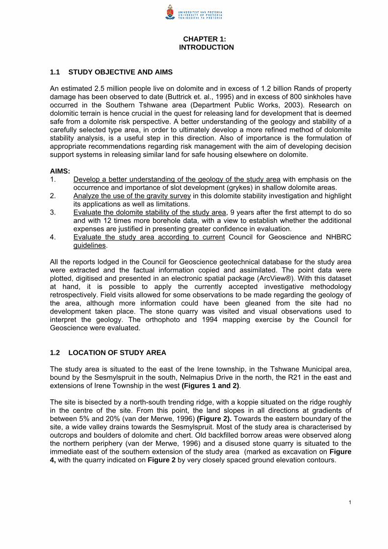
CHAPTER 1: INTRODUCTION
1.1 STUDY OBJECTIVE AND AIMS An estimated 2.5 million people live on dolomite and in excess of 1.2 billion Rands of property damage has been observed to date (Buttrick et. al., 1995) and in excess of 800 sinkholes have occurred in the Southern Tshwane area (Department Public Works, 2003). Research on dolomitic terrain is hence crucial in the quest for releasing land for development that is deemed safe from a dolomite risk perspective. A better understanding of the geology and stability of a carefully selected type area, in order to ultimately develop a more refined method of dolomite stability analysis, is a useful step in this direction. Also of importance is the formulation of appropriate recommendations regarding risk management with the aim of developing decision support systems in releasing similar land for safe housing elsewhere on dolomite. AIMS: 1. Develop a better understanding of the geology of the study area with emphasis on the
occurrence and importance of slot development (grykes) in shallow dolomite areas. 2. Analyze the use of the gravity survey in this dolomite stability investigation and highlight
its applications as well as limitations. 3. Evaluate the dolomite stability of the study area, 9 years after the first attempt to do so
and with 12 times more borehole data, with a view to establish whether the additional expenses are justified in presenting greater confidence in evaluation.
4. Evaluate the study area according to current Council for Geoscience and NHBRC guidelines.
All the reports lodged in the Council for Geoscience geotechnical database for the study area were extracted and the factual information copied and assimilated. The point data were plotted, digitised and presented in an electronic spatial package (ArcView®). With this dataset at hand, it is possible to apply the currently accepted investigative methodology retrospectively. Field visits allowed for some observations to be made regarding the geology of the area, although more information could have been gleaned from the site had no development taken place. The stone quarry was visited and visual observations used to interpret the geology. The orthophoto and 1994 mapping exercise by the Council for Geoscience were evaluated. 1.2 LOCATION OF STUDY AREA The study area is situated to the east of the Irene township, in the Tshwane Municipal area, bound by the Sesmylspruit in the south, Nelmapius Drive in the north, the R21 in the east and extensions of Irene Township in the west (Figures 1 and 2). The site is bisected by a north-south trending ridge, with a koppie situated on the ridge roughly in the centre of the site. From this point, the land slopes in all directions at gradients of between 5% and 20% (van der Merwe, 1996) (Figure 2). Towards the eastern boundary of the site, a wide valley drains towards the Sesmylspruit. Most of the study area is characterised by outcrops and boulders of dolomite and chert. Old backfilled borrow areas were observed along the northern periphery (van der Merwe, 1996) and a disused stone quarry is situated to the immediate east of the southern extension of the study area (marked as excavation on Figure 4, with the quarry indicated on Figure 2 by very closely spaced ground elevation contours.
1

1.3 PREVIOUS WORK The study area was first investigated in 1996 by an engineering geologist appointed by the then landowner and prospective developer. This earlier study comprised a gravity survey of most of the area, at 30 m grid spacing, the drilling of 19 rotary percussion boreholes, and excavation of 64 test pits. In late 1996 the local Town Council requested comment on the suitability of the area for residential development, from the Council for Geoscience, in fulfilment of the township establishment procedure (Article 96 of Ordinance No 15 of 1986). Only a small portion of this area was to be proclaimed as township with the remainder being subdivided in to one-hectare plots. There was insufficient information for the plots but in particular for the proposed township area, where little investigation was done due to the presence of extensive dolomite outcrop, and further work was recommended. The initial report was superceded by a later report as well as by a supplementary report for the proposed township. By mid-1997 a total of 63 rotary percussion boreholes had been drilled, 75 test pits dug and 56 super-heavy dynamic probe tests (DPSH) undertaken. Township proclamation proceeded in 1997, with land located on poorer areas from a dolomite risk perspective requiring more detailed investigations by a suitably qualified civil engineer (appointed by the potential home owner). The responsibility was effectively shifted to future home-owners to find suitable land for building. In 1998 the service mains were laid during which the engineering geologist mapped the trenches. In August 1998 the Housing Consumers Protection Measures Act was introduced, in essence, to protect housing consumers and to facilitate the establishment and functions of the National Home Builders Registration Council (NHBRC). This Council regulates the home building industry and publishes a home building manual containing technical requirements and guidelines (including specifications for dolomitic land) with which registered home builders/developers must comply. Enrolment of new houses with the NHBRC became mandatory from 1 December 1999. In accordance with the Home Building Manual, houses built on dolomitic land must be preceded by a dolomite stability investigation. This work also had to be reviewed by the Council for Geoscience. Although broad comments had already been made on the study area before the introduction of the new procedure, the NHBRC needed confirmation of the risk class as well as associated designations per individual stand. Due to a lack of information per individual property, it became necessary to investigate further all plots and stands. To date, over 750 boreholes have been drilled in the study area, over 100 test pits excavated and over 150 super-heavy dynamic probe tests undertaken by various consulting firms on behalf of their clients (Figure 27). Much of this study area is now built up. 1.4 GENERAL GEOLOGY The study area is located partly on the Lyttelton and Eccles Formations, Malmani Subgroup, Chuniespoort Group, of the Transvaal Supergroup (Figures 3, 4 and 5). The Chuniespoort Group is c. 2550-2400 Ma and unconformably succeeding rocks of the Pretoria Group are c. 2350–2100 Ma (Catuneanu and Eriksson, 1999). The Malmani Subgroup is subdivided into various formations of which some are chert-poor (e.g., Lyttelton Formation) and some are chert-rich (e.g., Eccles Formation). The Malmani Subgroup is conformably underlain by the Black Reef Formation, which is not present in the study area. The dolomites dip at approximately 20 degrees to the east. This is due largely to the emplacement of the Johannesburg basement granite-gneiss dome, as well as the intrusion of the c. 2.05 Ga Bushveld Complex, and possibly to a lesser extent due to the Vredefort impact event soon after.
2
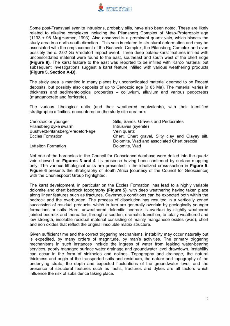
Some post-Transvaal syenite intrusions, probably sills, have also been noted. These are likely related to alkaline complexes including the Pilansberg Complex of Meso-Proterozoic age (1193 ± 98 Ma)(Harmer, 1993). Also observed is a prominent quartz vein, which bisects the study area in a north-south direction. This vein is related to structural deformation and may be associated with the emplacement of the Bushveld Complex, the Pilansberg Complex and even possibly the c. 2.02 Ga Vredefort impact event. Three deep palaeo-karst features infilled with unconsolidated material were found to the east, southeast and south west of the chert ridge (Figure 8). The karst feature to the east was reported to be infilled with Karoo material but subsequent investigations suggest a karst feature infilled with various weathering products (Figure 5, Section A-B). The study area is mantled in many places by unconsolidated material deemed to be Recent deposits, but possibly also deposits of up to Cenozoic age (≤ 65 Ma). The material varies in thickness and sedimentological properties – colluvium, alluvium and various pedocretes (manganocrete and ferricrete). The various lithological units (and their weathered equivalents), with their identified stratigraphic affinities, encountered on the study site area are: Cenozoic or younger Silts, Sands, Gravels and Pedocretes Pilansberg dyke swarm Intrusives (syenite) Bushveld/Pilansberg/Vredefort-age Vein quartz Eccles Formation Chert, Chert gravel, Silty clay and Clayey silt,
Dolomite, Wad and associated Chert breccia Lyttelton Formation Dolomite, Wad Not one of the boreholes in the Council for Geoscience database were drilled into the quartz vein showed on Figures 3 and 4, its presence having been confirmed by surface mapping only. The various lithological units are presented in the idealized cross-section in Figure 5. Figure 6 presents the Stratigraphy of South Africa [courtesy of the Council for Geoscience] with the Chuniespoort Group highlighted. The karst development, in particular on the Eccles Formation, has lead to a highly variable dolomite and chert bedrock topography (Figure 5), with deep weathering having taken place along linear features such as fractures. Cavernous conditions can be expected both within the bedrock and the overburden. The process of dissolution has resulted in a vertically zoned succession of residual products, which in turn are generally overlain by geologically younger formations or soils. Hard, unweathered dolomitic bedrock is overlain by slightly weathered jointed bedrock and thereafter, through a sudden, dramatic transition, to totally weathered and low strength, insoluble residual material consisting of mainly manganese oxides (wad), chert and iron oxides that reflect the original insoluble matrix structure. Given sufficient time and the correct triggering mechanisms, instability may occur naturally but is expedited, by many orders of magnitude, by man’s activities. The primary triggering mechanisms in such instances include the ingress of water from leaking water-bearing services, poorly managed surface water drainage and groundwater level drawdown. Instability can occur in the form of sinkholes and dolines. Topography and drainage, the natural thickness and origin of the transported soils and residuum, the nature and topography of the underlying strata, the depth and expected fluctuations of the groundwater level, and the presence of structural features such as faults, fractures and dykes are all factors which influence the risk of subsidence taking place.
3

CHAPTER 2: GEOLOGY
2.1 BEDROCK GEOLOGY AND LITHOLOGY The study area is located partly on the Lyttelton and Eccles Formations, Malmani Subgroup, Chuniespoort Group, of the Transvaal Supergroup (Figures 3, 4 and 5). The Malmani Subgroup is conformably underlain by the Black Reef Formation, which is not exposed in the study area. The bedrock underlying the study area hence consists of dolomites of the Malmani Subgroup. The latter is subdivided into various formations of which some are chert-poor (e.g., Lyttelton Formation) and some are chert-rich (e.g., Eccles Formation). 2.1.1 Composition Ancient carbonate rocks are predominantly composed of two minerals; calcite (CaCO3) and dolomite (CaMg(CO3)2). When a carbonate rock is dominated by calcite (more than 95%), it is called limestone, when it is dominated by dolomite (the mineral) it is called dolomite (the rock) (Warren, 2000). Limestone is thus a chemical or biochemical sediment consisting essentially of calcium carbonate (CaCO3), primarily in the form of calcite, and minor constituents such as silica, feldspar, pyrite and siderite. Dolomite, as a rock, contains more than 90% dolomite and less than 10% calcite as well as detrital minerals and secondary silica (chert). Very few, if any, sedimentary dolomites are truly stoichiometric, i.e. CaMg(CO3)2, and are better represented as: Ca(1+x)Mg(1-x)(CO3)2, encompassing the spectrum from calcian to magnesian dolomites (Warren, 2000). Researchers seem to agree that the carbonate rocks in the Malmani Subgroup are essentially a diagenetic dolomitic product after primary limestones, with few limestone bands, lesser cherts and minor interbedded shale and chert-in-shale breccias (Button, 1973; Beukes, 1978; Clendenin, 1989). 2.1.2 Deposition and Diagenesis The onset of limestone deposition in the Transvaal basin has been estimated at 2550 ± 3 Ma (Walraven and Martini, 1995). The Archaean and early Proterozoic life record includes exclusively prokaryotic bacteria and cyanobacteria (Schopf and Klein, 1992). The limestone precipitated in favourable environmental conditions by cyanobacterial photosynthesis (Beukes, 1987). The vast majority of Archaean and early Proterozoic carbonates are stromatolitic (i.e. organo-sedimentary) deposits or the direct result of erosion and weathering of stromatolites (Eriksson and Altermann, 1998). The limestone then underwent dolomitization in an environment where meteoric and marine water mixed and the saline brine became supersaturated with respect to magnesium and silica, and undersaturated with respect to calcite, thereby increasing the potential for dolomitization and chertification (Dorag or mixing zone Model) (Eriksson and Warren, 1983). Sufficient evidence exists to indicate that dolomite and chert are syndepositional, the minerals forming contemporaneously with sedimentation. 2.1.3 Lyttelton Formation The Lyttelton Formation (Figure 4) outcrops in places in the southwestern part of the study area. This Formation normally consists of light grey, chert-poor dolomite with minor chert near its base. The rock weathers to a dark chocolate brown coloured soil. No significant chert breccia is associated with this formation (Button, 1973). The topography of an area underlain by Lyttelton Formation is normally flat, as is proven to be the case in this study area. Extensive areas of outcrop were observed. The contact between the Lyttelton Formation and the
4

overlying Eccles Formation is normally taken where there is an increase in the chert concentration and the colour of the dolomite changes from dark brown to grey (Obbes, 1995). The chert content gradually increases until the typical alternating chert and dolomite layers or “bread and butter” structure of the Eccles Formation are encountered. Plate 1 shows such an outcrop found in the study area. 2.1.4 Eccles Formation The Eccles Formation (Figure 4) underlies a broad band in the central and eastern portion of the study area. This formation consists of well bedded, alternating chert and light grey dolomite layers. The dolomite is medium to course grained with small calcite crystals in a non-crystalline matrix. Cyanobacterial laminations or stromatolites and ripple marks are common in the formation (Obbes, 1995). Outcrops of Eccles Formation are widespread in the study area, and in particular, prominent in the disused quarry. Residual chert and Eccles-derived chert breccias are present at the top of the formation. Obbes (1995) identified 9 zones in the Eccles Formation in the Broederstroom area based on certain chert bands, stromatolites and chert-in shale breccia. Due to the fact that much of the present study area is now built up, it was not possible to attempt to identify the various zones in this area. Chert breccia is often grouped with the Rooihoogte Formation as part of the so-called, informal unit, the “Giant Chert Formation”. However, chert breccia associated with the Eccles Formation as either intraformational or secondary weathering products can be expected. Both types have been found at various locations in the study area. Quartz-veins are commonly associated with shear zones, present in the Eccles Formation. A very well-defined quartz vein, approximately 5 m wide, bisects the study area and presents as a gravity low anomaly, showing that the vein formed along a major fracture in the rock unit. 2.2 KARST DEVELOPMENT 2.2.1 Weathering of Dolomite Although karst weathering commonly occurred during Karoo to recent times (approx < 250 Ma), there were several much older karst events in the preserved Transvaal basin carbonates (Eriksson and Altermann, 1998). A major karst event, for instance, took place during the time interval represented by the unconformity (c < 2.436 Ga - ≥ c. 2.35 Ga) that separates the Chuniespoort and Pretoria Groups (Martini et al., 1995). Large cavities are not only associated with this contact but also occur at several hundred metres below this level. The weathering process is well summarised in the Guideline for engineering geological characterisation and development of dolomite land (2003): Rain water (H2O) takes up carbon dioxide (CO2) in the atmosphere and soil (where the concentration of this gas may be up to 90 times greater than in the atmosphere) to form a weak carbonic acid (H2CO3). The weakly-acidic groundwater circulating along tension fractures, faults and joints in the dolomitic succession causes leaching of the carbonate minerals. The solubility of dolomite is high in comparison to other rocks, but significant solution cannot be observed over short periods (months and years). This process may be represented as follows: CaMg(CO3)2 + 2 H2CO3 → Ca(HCO3)2 + Mg(HCO3)2
5
The process of dissolution progresses slowly in the slightly acidic groundwater (above and at the groundwater level). The resultant bicarbonate-rich water emerges at springs and is carried away.

This process of dissolution has resulted in a vertically zoned succession of residual products, which in turn are generally overlain by geologically younger formations or soils (Figure 7). Hard, unweathered dolomitic bedrock is overlain by slightly weathered jointed bedrock and thereafter, through a sudden, dramatic transition, passes upwards to totally weathered and low strength, insoluble residual material consisting of mainly manganese oxides (wad), chert and iron oxides, that reflect the original insoluble matrix structure. Depending upon the local subsurface structure, this very low strength, porous and permeable horizon may in certain locations be up to several tens of metres thick but is generally less than 10 metres thick. With the passage of geological time, concurrently with the downward progression of the intense weathering of the dolomitic bedrock, compaction by the mass of the overlying materials has resulted in a progressive densification of these low strength materials. Consequently, the vertical succession of the residual products of weathering reflect an upward increase in strength and a decrease in porosity and permeability. This process results in a decrease in overburden quality with depth, which in turn leads to higher rates of penetration, so often noted in drilling investigations, when the dolomitic bedrock is approached. Infiltrating water from leaking services or surface accumulations acting on this low-density material results in a loss of support through slumping or subsurface erosion. Given sufficient time and the correct triggering mechanisms, instability may occur naturally but is expedited many orders of magnitude by man’s activities. The primary triggering mechanisms in such instances include the ingress of water from leaking water-bearing services, poorly managed surface water drainage and groundwater level drawdown. Instability can occur in the form of sinkholes and dolines. Topography and drainage, the natural thickness and origin of the transported soils and residuum, the nature and topography of the underlying strata, the depth and expected fluctuations of the groundwater level, and the presence of structural features such as faults, fractures and dykes are all factors which influence the risk of subsidence taking place. 2.2.1.2 Sinkholes Karst-related ground movement encompasses the terms sinkhole and doline. A sinkhole is a feature that occurs suddenly and manifests itself as a hole in the ground. A classification of sinkholes in terms of size as proposed by Buttrick and Van Schalkwyk (1995), is shown in Table I. Jennings et al. (1965) and Brink (1979) have described the mechanism of sinkhole and doline formation in detail. The mechanism of sinkhole formation is briefly summarised as follows:
• Cavities exist within bedrock or the overburden, which may be in a state of equilibrium. • Active subsurface erosion caused by concentrated ingress water will result in
transportation (mobilisation) of materials downwards into the nearest cavity (receptacle).
• Headward erosion leads to successive arch collapse. The last arch may be stable for a considerable length of time and is sometimes supported by a near-surface layer of hardpan ferricrete.
• A triggering mechanism leads to the breaching of the last arch. Particularly in the case of small sinkholes, the cross-section resembles a bottleneck (narrow opening at surface), a shape that may be maintained for some time.
6
A number of independent conditions are necessary before a sinkhole can form:
• There must be adjacent rigid material to form abutments for the roof of the void. • A condition of arching must develop in the residuum. • A void must develop below the arch in the residuum. • A receptacle must exist below the arch to accept mobilised material. • Some disturbing agency must arise to cause the roof to collapse.
A number of old sinkholes were found in the study area during the 1996 investigations. Although there is some doubt as to whether all of these were indeed sinkholes (it is possible that at least two were old small borrow pits), the majority appear to have been natural (i.e. not induced by man’s activities) features. These features had abundant plant life. All features were backfilled according to the appointed engineers’ specification and a servitude registered over them to ensure that no structures would be built on them. The registered servitudes, which indicate the location of these features, are presented in Figure 2. Plate 2 shows how these features were backfilled. In 1998 a sinkhole fell through a thin cover of landfill in the western part of the study area; refer to Plate 3. A broken clay pipe protrudes into the feature as a telltale sign of a possible cause of the sinkhole. Dolomite pinnacles are clearly visible in the sidewall. In 2002 the reservoir on the koppie leaked and discharged large quantities of water underground. One stand was affected dramatically, and a sinkhole and 2 dolines formed. This area was investigated by means of further drilling to determine the extent of the subterranean damage. The damage was found to be limited, the features backfilled and compacted. A house has now been built upslope from these features. Detailed drilling within the footprint of the house did not reveal poor subsurface conditions.
2.2.1.3 Dolines A doline is an enclosed depression, which forms as a result of the compression at depth of low-density dolomite residuum. Two main types of dolines can be identified based on the mechanism of formation, namely dewatering-type and surface saturation-type dolines. A third type, which can be referred to as an incompletely developed sinkhole, has a similar surface appearance to the former two types but is caused by the erosion of subsurface materials. Distinction was made in the Guideline for engineering-geological characterisation and development of dolomitic land (2003) between: 2.2.1.3.1 Dewatering-type Doline A dewatering-type doline, occurs gradually and typically manifests itself as a large enclosed depression. The mechanism of this type of doline formation is briefly summarised as follows:
A deeply weathered zone within the dolomite rock is filled with potentially highly compressible material, part of which is submerged below the groundwater level.
Rapid drawdown of the groundwater level results in exposure of the previously submerged and unconsolidated debris.
Compression may be excessive and the rate of surface settlement is rapid if a thick succession of wad is exposed by this drawdown.
The settlement manifests as a depression at surface. Surface tension cracks occur in the peripheral areas of differential movement.
7

2.2.1.3.2 Surface Saturation-type Doline These dolines are typically relatively small (i.e. less than 5 m in diameter). The mechanism of doline formation in this instance is as follows:
An area is underlain by compressible dolomitic material at relatively shallow depth with the groundwater level within or below the compressible material. The movement of the groundwater level does not play a role in ground surface movement.
The surface materials are saturated due to poor water management i.e. poor drainage or a leaking wet-service.
The wetting front penetrates the surface material and reaches the low-density material. A surface depression occurs gradually due to the increased load of the near-surface
materials on the deeper lower-density materials, which settle into a denser state because of saturation.
The movement will generally decrease rapidly when the cause of wetting is stopped. The size of the features depends on the profile underlying the saturated area i.e. the
thickness, nature and depth of the near-surface and deeper lower-density materials, the configuration and depth of the bedrock dolomite and the extent of the saturation (e.g. the extent of the area covered by water, the volume of the water and the length of the period during which saturation occurs).
Two of the three features which developed due to the leaking reservoir, alluded to in the last paragraph of Section 2.2.1.2, can best be described as a surface saturation-type doline. In 2003 a suspected wet-service leak together with poor stormwater drainage resulted in a large semi-circular depression forming between two properties on the western part of the study area. This feature caused a swimming pool and house to crack extensively. It was not possible to repair the damage and the house was subsequently demolished and pool backfilled. Plate 6 shows one of the cracks that developed in the house. 2.2.1.3.3 Partly Developed Sinkholes The premature termination of subsurface erosion by ingress water may also result in a settlement feature at surface, which appears to be similar to a doline. 2.3 SEDIMENTARY HISTORY The Transvaal Supergroup comprises lowermost volcano-sedimentary deposits (‘protobasinal units’) followed by the thin Black Reef Formation, the carbonate-banded iron formation succession (Chuniespoort-Ghaap Groups, which include the Malmani-Campbellrand Subgroups, respectively), overlying clastic sedimentary and volcanic rocks (Pretoria Group; possibly Postmasburg Group; Griqualand West Supergroup) and uppermost Rooiberg Group lavas (Eriksson et al., 1995). These rocks are preserved in three macro-structural basins, with the Malmani-Campbellrand carbonates representing one of the oldest preserved carbonate platform successions in the stratigraphic record (Altermann and Nelson, 1996). The carbonate platforms developed between 2640 and 2516 Ma and probably extended across all three preserved basins (Griqualand West, Kanye basin in eastern Botswana, and Transvaal), covering an area in excess of 600 000km2 (Beukes, 1987). The evolution of these basins is ascribed predominantly to magmatism, palaeoclimate and eustasy with plate tectonics playing a sporadic role (Eriksson et al., 2001). Supercontinent amalgamation however played a pivotal role towards the end of Transvaal deposition and at the time of Bushveld intrusion (2.05 Ga) (Eriksson et al., 2001). The carbonate succession is almost 1200 m thick and the geometry of the preserved succession indicates sheet-like layers with little variation across the basin (Eriksson and
8

Reczko, 1995). The upper part of the carbonate succession has been eroded in the south and southeast of the preserved Transvaal basin prior to Pretoria Group deposition, so that these dolomitic Formations are absent in the greater area of interest to this study. Major karstification took place during this time (c. 2430 – 2320 Ma). The basal chert breccia of Rooihoogte Formation is a product of an eroded and deeply weathered dolomitic land surface. The sub-Pretoria hiatus was followed by deposition of basal Rooihoogte fan sediments (Martini et al., 1995). Large cavities are not only typically found at the contact, but also several hundreds of metres below this level (Martini et al., 1995). Karstic weathering has affected the Chuniespoort carbonates since deposition and it is not known how many such cycles have occurred up until Karoo times (250 Ma). The intrusion of the c. 2.05 Ga Bushveld Complex, and possibly to a lesser extent the uplift of the Johannesburg basement granite-gneiss dome, as well as the Vredefort impact event (c. 2.02 Ga) tilted the Transvaal Supergroup up to 25 degrees to the north (Jansen, 1977), thereby leading to dip-related exposure of all beds, including the carbonates in question. At the end of the Jurassic, rocks of the Karoo Supergroup covered large areas of Southern Africa. With the breakup of Gondwana (144 Ma ago) through rifting, a Great Escarpment along Southern Africa was created and offshore sedimentation on the southern coast began. Partridge and Maud (1987) researched and identified various erosional cycles after the cessation of Karoo sedimentation. Their work revealed that a single cycle of erosion prevailed from the time of rifting and break-up of the super-continent to the early Miocene (24 Ma). By the end of this period a gentle pedeplain (the African surface) extended across most of Southern Africa at elevations of 500-600 m. Most erosion took place during the earlier part of this interval and produced thick late Jurassic and Cretaceous sedimentary sequences. Modest renewed uplift of 150-300 m in the Miocene tilted the continent slightly to the west and initiated a new (Post African I) landscape cycle, accompanied by renewed sedimentation, although at lower rates than during the Cretaceous. This cycle was terminated near the end of the Pliocene. The relatively short duration of this erosion resulted in imperfect planation to levels of 100 to 300 m below the African surface. A second uplift of major proportions at the end of the Pliocene raised the eastern interior of the subcontinent by as much as 900 m, with the western areas experiencing much smaller uplift. The ensuing Post-African II cycle is manifested chiefly in downcutting along major rivers of the interior. These cycles of uplift and denudation have resulted in erosion of large portions of the sedimentary rock sequences, which were deposited in the Gauteng area, and the weathering of in situ material to great depths. The weathering products remained preserved in narrow valleys, which were likely to have been quite common in the Eccles Formation of the Malmani Subgroup. 2.4 KARST TOPOGRAPHY The Transvaal Supergroup rocks were also subjected to complex faulting and folding along the northeastern rim of the Johannesburg Dome (Bosch, 2005). Displacement and duplication of the Transvaal rocks by faulting is common to the east and south east of Pretoria. The karst topography is also well developed along these water exploited structural features. 2.4.1 Borehole Deduced Topography Boreholes drilled in the study area indicate a well-developed karst topography. The karst topography is overlain by variable thicknesses of residual deposits and transported sediments. Figures 8 and 9 present a 3-D plot of the elevation of dolomite bedrock. All the boreholes that actually struck dolomite bedrock (confirmed by drilling at least 6 m into rock) were used in the plot. Judiciously selected ‘posts’ (annotated borehole positions) were superimposed on the plot to flag reference points.
9

As is typical in karst in Gauteng, the karst topography is significantly different from the ground topography. This can be substantiated by considering the dolomite bedrock high ridge (Figure 8, 1), the narrow low trough (Figure 8, 2), the deep basin (Figure 8, 4) and an extension of this basin (Figure 8, 3). The bedrock high ridge has a northeast-southwest orientation and lies to the east of boreholes 61 and 47. In contrast the ground topography presents a high ridge with a northwest-southeast orientation, with the ridge passing to the east of borehole 47 and west of borehole 50 with the northern portion of the ground topographic ridge lying to the west of the cluster of boreholes 5, 1 and F. This high ridge drops to a plateau-like area to the east and west with a relatively lower ridge extending to the southeast, partly isolating a sub-basin (Figure 8, 3) from the deeper main basin (Figure 8, 4), as well as to the southwest, an area marked by extensive rock outcrop between boreholes 40, 30 and 8 (on the edge of the plot). The narrow dolomite bedrock trough is masked by gentle (relatively flat) ground topography. The relatively lower ridge in the south-east does not coincide with the relatively low ridge present on the ground topography but lies rather to the north of this ground topographic feature. The topographic ridge in fact coincides with the edge of the main deep basin. Some very poor conditions were encountered along the edge of the basin between boreholes 47 and 50. Likewise, extensive poor conditions were also encountered along the western flank of the main bedrock ridge. This suggests that poor conditions are prevalent along steeper bedrock slopes. The steeper bedrock areas along the sub-basin as well as the narrow low trough are slightly different in that palaeo-infill has replaced the dolomite residuum. Of notable absence in this plot is an indication of the micro-bedrock topography, in particular in the shallow dolomite areas (i.e. those areas where bedrock is near to ground surface, for instance shallower than 8 m). This is mainly due to the fact that boreholes that struck narrow grykes (solution-enlarged vertical joints which form slots in the bedrock), were most often prematurely terminated in the unconsolidated material and hence were not used to contour bedrock topography. A further set of boreholes were drilled into dolomitic floaters and broken pinnacles before encountering more insoluble residuum and finally dolomite bedrock. These boreholes were also excluded from the plot. An example of a few grykes of rather limited dimension is displayed in Plate 5, which was taken in the disused quarry. In order to demonstrate the existence of these features elsewhere in the study area, two cross-sections were drawn on areas of known shallow dolomite, one in an east-west direction and another in a north-south direction (Figure 5). These cross-sections clearly show the presence of grykes, although their widths and depths are sometimes speculative. Although the grykes in Plate 5 seem to terminate at similar shallow depth, borehole information does seem to suggest that the depths of grykes can vary. Figure 10 presents a diagrammatic representation of a shallow dolomite area, drawn from information obtained from the cross-sections as well as visual observations of sinkholes that have occurred in such areas. A photo of a sinkhole which exposed the dimensions of a gryke has been included for clarity together with a three dimensional perspective. The cross-sections seem to suggest that grykes do not have one preferred orientation, in fact there are at least two preferred orientations. This is borne out by the gravity survey as well, which shows a low trough in a north-west south-east orientation as well as an east-west orientation.
10

2.4.2 Remote-sensing Deduced Topography Figure 26 presents the results of the gravity-deduced topography. One of the 8-m-to-dolomite-bedrock contour lines has been flagged. This line theoretically separates the shallow bedrock areas from the deeper bedrock areas. In order to establish the accuracy of this line or the residual gravity map for that matter, a comparison must be drawn between the actual depths to dolomite bedrock presented in boreholes and the depth to dolomite bedrock contours deduced from the residual gravity map (refer to Section 3.4). 2.4.3 Waltham and Fookes Karst Types Waltham and Fookes (2003) proposed an engineering classification of karst based on the assessment of karst world-wide. They were of the opinion that a classification that identifies certain essential parameters that influence dolomitic ground conditions and the degree to which these are present, is useful to the civil engineer when faced with the task of recommending engineering solutions. The classification has as its parameters: sinkhole frequency, rockhead variability (or bedrock topography) and sizes of underground caves. Five classes are defined: juvenile, youthful, mature, complex and extreme karst. Of interest in terms of bedrock topography for the study area is that areas where pinnacled dolomite exists with a relief of 5-20 m is termed complex karst, and areas where pinnacled dolomite exists with a relief of greater than 20 m with loose pillars undercut between deep soil fissures, are termed extreme karst. The challenge in applying such classification in South Africa is to determine which karst types are truly present on a site, as almost all our karst is mantled and masked by soil horizons. There seems to be overwhelming evidence in the study area that extreme karst prevails for most of the area. Some adaptations are needed to the morphological features depicted in the extreme and complex karst type schematic diagrams to better reflect general local conditions in South Africa. Figure 7 shows an attempted and generalised adaptation for the typical morphological features expected in the study area. 2.5 POST KARST GEOLOGY 2.5.1 Karst-fill Deposits The irregular dolomite bedrock, which mostly already contained residual dolomite successions, was infilled by younger sediments. These sediments are therefore also of irregular distribution and thickness and may be categorised as consolidated and unconsolidated. 2.5.1.1 Consolidated Material The initial investigation reported the presence of a palaeo-infill channel, scoured out by glacial action and infilled with argillaceous and arenaceous deposits (van der Merwe, 1996). Six boreholes were originally drilled in this so-called channel, and revealed 5 to >26 m of red clayey silt with angular chert fragments, pink laminated clayey silt greater than 28 m, described as Karoo mudrock, 12 m of red silt with chert gravel and 12m of pale grey pinkish red laminated clayey silt and soft rock shale. Additional drilling (54 boreholes) did not reveal extensive Karoo material, with only 4 boreholes potentially reporting material of Karoo origin (described as yellowish khaki sandy silt and mudrock fragments between 5 m and 45 m depth, and orange greyish, yellow soft rock shale and yellowish purple shale at depths of 31-44 m, 34-42 m and 6-25 m, respectively). The consultants who undertook the logging of their boreholes were often not sure of the actual origin of the material or whether the material was in situ weathered Karoo or transported Karoo material, and always reported palaeo-infill material as of a specific stratigraphic origin.
11

Based on the depth-to-bedrock plot as well as a review of all the material described as palaeo-infill, it seems rather unlikely that the originally described valley was, firstly, a steep valley scoured out by glacial action (Figure 9), secondly, infilled by a thick layer of Karoo material, and thirdly, the only valley in the study area. That there are significant and deep karstic valleys is certain, these are visible on the bedrock elevation plot (Figure 8). That these may have been infilled by Karoo material at some time in geological history seems plausible, the description of some of the boreholes can only suggest Karoo origin. However, due to the fact that the chips and fine material arrives at surface from the borehole as a disturbed sample, it cannot be determined whether the material is in situ weathered Karoo or transported Karoo material. This is further complicated by the potential for sample contamination and the fact that penetration times cannot distinguish between in situ weathered Karoo or transported Karoo. It seems likely that the material encountered in the valley is transported Karoo material as well as more recent material of mixed origin, deposited on the karstic landscape and best preserved (protected from later erosion) in the narrower features, as confirmed in the narrow trough and sub-basin identified on Figure 8, but also identified in various narrower features not immediately evident on the bedrock elevation plot. More sporadic occurrences of Karoo material outside the trough and sub-basin could easily be misconstrued to form part of a major basin and lead the engineering geologist to assess a much larger area as having uniform risk. 2.5.1.2 Unconsolidated Material Unconsolidated material includes material of both residual and transported nature. The evolution of weathering in dolomite has been discussed in Chapter 2.2.1. Residual dolomite hence may consist of chert and wad. Where residual dolomite is removed and transported, it is likely that chert and its weathering products survive the process and are deposited in various karst features. Kalahari sands of aeolian origin are common across much of SA. These often collected in surface depressions, including those of karstic origin. These were mixed by hillslope wash processes with other, in situ products, and all dumped into karst features (e.g., Wilkins, 1985). In some instances fluctuating water levels in these deposited layers led to silicification. These might erroneously be identified as the chert breccia found at the top of the Eccles Formation or even chert breccia of the Rooihoogte Formation. Although from an engineering geological or geotechnical perspective the age and origin of a chert breccia is often only academic it becomes of great significance if the breccia is anticipated to be uniform and thick, when it should be deemed to be thin and variable. The east-west cross-section of the study area (Figure 5) shows a first generation weathered chert, which mantles the dolomite succession on the eastern section. This chert may be residual in situ weathered material of the Eccles, produced during erosional cycles after original deposition of dolomite, preserved in a number of karst valleys or a major karst valley. The deep valley could be ascribed to erosion along fractures and faults in the dolomite. The quartz vein in the study is a telltale sign that the dolomite in the eastern part of the study area was significantly fractured. Syenite intrusions are also common along such features, with a sill having been identified at depth and along stratigraphic strike in the study area. The intrusion has weathered considerably since emplacement and further leaching may have occurred along the rock face of the fault zone. A second generation of weathered products was deposited as alluvium in the valley where a palaeo-stream once flowed. This palaeo-stream seems to coincide roughly with the present day Sesmyl Spruit. A third generation of weathering product was deposited subsequent to this on the hill slopes of the newly developed ground topography, and represents the chert rubble and colluvium found as a layer of variable thickness along the slopes of the present ground slope. Ferruginisation is common in this material. Obbes (2000) refers to an intraformational chert breccia at the top of the Eccles Formation, named the Leeuwenkloof Member, which was identified in the Broederstroom District. This Member consists of angular chert fragments and blocks in a silicious matrix. Obbes (op. cit.)
12

identified clasts, which exhibit a jig-saw fracture pattern. He presents this as evidence of a cohesive unit, which was broken in situ, presumably due to karstification of underlying dolomites. The first generation weathered chert, which mantles the dolomite succession on the eastern section of the study area may be equivalent to the Leeuwenkloof Member, although this cannot be confirmed as the drilling process destroys the original shape of the fragments. Various boreholes in this area may have encountered the Leeuwenkloof Member, which in turn is underlain by typical Eccles Formation residuum, which in itself may also be chert-rich. Obbes (op. cit.) also refers to the younger Diepkloof Formation, which overlies the residual karst breccia in his study area. The Diepkloof Formation consists of poorly sorted angular to subangular blocks of chert in a poorly silicified and ferruginised matrix. The Formation is considered to be 60 Ma or younger because it is found above the African Erosional surface. This Formation may well be the third generation weathering product identified in the study area. The identification and naming of formal stratigraphic units within a succession of highly complex karstic weathering history is not without controversy. However, in attempting to unravel the weathering history, one better appreciates the impact this has on the stability of the area.
13

CHAPTER 3: DOLOMITE STABILITY
3.1 METHODOLOGY APPLIED SINCE 2001 The evaluation of dolomitic land is complex because: (a) geophysical techniques cannot be relied upon solely for provision of information, (b) the cost of drilling is high and only effectively probes a small vertical cylinder of the
geological succession, (c) dolomite bedrock topography and overlying surficial deposits are usually variable and (d) the difficulty in quantifying and spatially delineating risk has legal implications and
ramifications. (Council for Geoscience/South African Institute of Engineering and Environmental Geologists, 2003).
Various authors have over the years attempted to classify dolomitic land. A summary was presented in the PhD thesis titled: “Characterisation and appropriate development of sites on dolomite” (Buttrick, 1992). The method proposed in this thesis was termed the “method of scenario supposition for stability evaluation of sites on dolomitic land in South Africa”, which has been applied widely by the industry, certainly since 1995, when the method was published (Buttrick, 1995). The method was successful in focussing the attention of investigators of dolomitic land on the various factors that contribute to instability. However, with time it became evident that modification and further clarification of various concepts was necessary. The modified method was named “method for dolomite land hazard and risk assessment in South Africa” (Buttrick et al., 2001). Four important concepts were defined in this 2001 methodology: • Hazard Hazard is defined as an event that can cause damage to property or even loss of life and refers to a sinkhole or a doline of a certain size. Sinkhole sizes as proposed by Buttrick and van Schalkwyk (1995) are presented in Table J. • Risk Risk is defined as the possibility/probability of meeting danger or the chance of encountering a hazard. In the case of development on dolomite, both inherent risk and development risk are evaluated in context of the factor of time. • Inherent risk Inherent Risk refers to the chance of formation of a certain-sized sinkhole or doline within the postulated scenario of dewatering or non-dewatering. It must be assumed that the site has been developed and treated inappropriately, resulting in all mobilising agencies becoming operative. An area may be considered to constitute a low, medium or high risk where (statistically) such land has historically precipitated up to 0.1, between 0.1 and 1, and greater than 1 ground movement events per hectare per 20-year period, respectively. The site retains its inherent risk irrespective of the type of development recommended or intended.
14

• Development risk Development risk refers to the likelihood of damage to property, loss of life or financial loss, and is to be considered acceptable or unacceptable. The basic design of a township is a key element in the strategy to minimize the impact of a proposed development. Once the hazard and inherent risk of a site has been established, a type of development can be selected that is appropriate and will result in an acceptable development risk. According to the Buttrick et al. (2001) methodology, the following steps should be followed in assessing a dolomitic site: Step 1: Field reconnaissance and a desk study are undertaken to collate all existing information. Planning of the investigation takes place. Step 2: By using geophysical tools, other relevant remote sensing techniques and field information (geological and topographic mapping), the site is subdivided into potential morphological zones. These zones are areas that are anticipated to have similar subsurface conditions (depth to bedrock, extent of weathering, residual materials present). Step 3: Boreholes are drilled to investigate the zones. Step 4: The individual borehole characterisations and all available information are integrated and the boundaries and characteristic conditions of the original zones are refined. The stability characterisation of a site is carried out. The method requires some hypothesis regarding the probable impact of man’s activities on the dolomitic environment during the lifetime of the development. The potential stability of the land is reviewed in the context of either a dewatering (where the groundwater level could be, or has been, appreciably lowered) or a non-dewatering scenario. Step 5: The spatial distribution of inherent risk is decided upon, and a risk zonation map can be drawn. Step 6: Appropriate development types are selected for each zone and suitable precautionary measures are identified. The particular type of development envisaged in relation to the Inherent Risk characterisation is of cardinal importance to the Development Risk, which determines the safe and successful long-term viability of a project. This Buttrick et al. (2001) method was also applied to the present study area. 3.2 INVESTIGATIVE METHODOLOGY 3.2.1 Phases of Investigation Over the years it has become evident that investigative requirements need to be differentiated (Council for Geoscience/South African Institute of Engineering and Environmental Geologists, 2003). An investigation undertaken to give preliminary indications of suitability of a site for development from a dolomite risk perspective is based on a minimum amount of information. This investigation cannot be used to assign risk to an individual stand or small portion of the site as the confidence level with which the data were interpreted is low. The correct phase must be applied, as more detailed information is required on which the interpretation can be
15

based. 3.2.1.1 Reconnaissance Phase This phase primarily involves a desk study during which all available information is collated. Reports of previous investigations covering the entire or part of the site and surrounding areas should be reviewed. The developer and investigator should discuss the intended purpose of the land. A site visit is likely to be needed to obtain clarity on various issues that have come to light during discussions. 3.2.1.2 Township Feasibility Phase 3.2.1.2.1 Phase 1 This investigation may involve geophysical surveys (usually gravity surveys), drilling (typically rotary percussion drilling), subsurface profiling, test pit excavation and augering (and profiling thereof), penetrometer testing, in situ testing and disturbed or undisturbed sample testing. This is followed by an evaluation of all the data and culminates in the general delineation of geotechnical and dolomite stability risk and hazard zones. The first phase evaluation will, furthermore, enable the investigator to formulate recommendations pertaining to density of units, remedial and precautionary measures and mitigation of risk in the form of a risk management plan. 3.2.1.2.2 Phase 2 A possible second phase of investigation may be required during which detailed or additional work is done to confirm or amend the first attempt at risk zonation. The data gathered during the soils investigation may also assist in the finalization of the risk zonation. The second phase evaluation will assist the investigator in refining the initial recommendations. The infrastructure is designed in light of the findings of the feasibility phase and in accordance with the Code of Practice and NHBRC requirements. Although this task is chiefly the responsibility of the engineer, the geological consultant responsible for the investigation may make a valuable input with regards to suitable foundation types, for instance. 3.2.1.3 Design Phase Investigation Further investigations are undertaken in a zone or part thereof to determine its suitability for a specific purpose, such as for a school or shopping complex. 3.2.1.4 Construction Phase Service trenches should be inspected in order to confirm the conditions anticipated and to investigate or re-evaluate problem areas encountered. Confirmation should be sought that precautionary measures have been implemented and recommendations have been adhered to. These findings, as well as the implications of discrepancies, which may become evident in this inspection, must be documented in a construction report. Once development has progressed to this stage it is difficult to change layout plans but certain engineering solutions may be more appropriate and should be considered/adopted as necessary. Palaeo sinkhole conditions when encountered will require further investigation and may result in stands previously deemed developable (D2/D3) being designated as undevelopable (D4).
16

3.2.1.5 Completion Phase Certification that precautionary measures have been implemented and that the final layout of the development has taken cognisance of the risk zonation must be given. The investigator should liaise with the developer, ensuring that the final risk management plan is comprehensive and site specific, with clear guidance on the procedures to be followed in gaining input for deciding on follow-on action. Responsibility must be identified and delegated to appropriately qualified and experienced persons where possible (this is particularly important in the case of sectional title developments). Finally, the developer must confirm that all procedures for the plan are in place. 3.2.2 Investigative Methodology Applied to the Study Area Although, essentially the initial investigative work was undertaken between 1996 and 1998, since 2000 over 700 boreholes have been drilled in the study area, over 100 test pits excavated and over 150 DPSH tests undertaken by various consulting firms on behalf of their clients. This work until recently had never been collated. All the reports lodged in the Council for Geoscience geotechnical database for the study area were extracted and the factual information copied and assimilated for the study area. The point data were plotted, digitised and presented in an electronic spatial package (ArcView®). With this dataset at hand, it is possible to apply the currently accepted investigative methodology retrospectively, the only limitation being that most observations were not made first-hand, but by the consultants who undertook the various investigations; it thus needs to be assumed that the observations would have been the same if they had been made first-hand. Field visits allowed for some observations to be made regarding the geology of the area, although more information could have been gleaned from the site had no development taken place. The stone quarry was visited and visual observations used to interpret the geology. The orthophoto and 1994 mapping exercise by the Council for Geoscience were evaluated. Three cross-sections were produced, two in an east-west direction and one in a north-west/south-east direction, using key data points (Figure 5). 3.2.2.1 Assimilation of Available Data and Information All available data and information pertaining to the study area and its immediate surrounds were assimilated. Normally, this work would form part of the reconnaissance phase of investigation. The reports of previous investigations covering the study area (1996-1997) as well as the reports by various consultants for individual stands were reviewed. Information such as borehole logs were summarised and captured in a spreadsheet. Information recorded was: depth to dolomite bedrock (if any was struck), depth of borehole, extent of chert, extent of palaeo-infill and type of infill, extent of cavities, extent of wad and cavernous conditions, extent of igneous material, sample and air loss occurrences and x-, y- and z co-ordinates of data points. Short summaries were transferred onto a plan of the entire study area. 3.2.2.2 Mapping Limited field mapping was undertaken by the Council for Geoscience in 2005 in order to provide further detail of the underlying distribution of the geological formations and the geological structure interpreted from the existing 1:50 000 geological map (Geological Survey of South Africa, 1973) as well as the unpublished 1: 10 000 mapping exercise of 1994. The results of the main services trench mapping exercise in 1998 (no report was produced) were also taken into consideration.
17

3.2.2.3 Hydrogeological Study The presence of dolomitic groundwater has a significant impact on the stability of dolomitic land. Due to the importance of the hydrogeology, this topic is elaborated on in detail in Paragraph 3.3. 3.2.2.4 Geophysical Surveys Despite various advances in geophysics, the gravity method is still the most widely used remote sensing method applied on dolomitic land. Other geophysical methods such as thermal infrared imagery may resolve more detail that cannot be deduced properly from the gravity survey, however at present, the method of evaluation is mostly dependant on the interpretation of the gravity survey as a minimum. Due to the importance of the gravity survey results, this topic is elaborated on in detail in Paragraph 3.4. 3.2.2.5 Rotary Percussion drilling The drilling phase of an investigation should be based as far as possible on the interpretation of the gravity map. In the 1996 investigation, the drilling and gravity survey were conducted concurrently as a result of time constraints. The gravity map was used to some degree to correlate and interpret the results of the percussion drilling and to aid in the identification and delineation of zones of varying instability risk. Percussion drilling was conducted over a period of 9 years, by means commonly of a drill rig using a button drill bit of 165 mm diameter and with compression pressure of 16-18 Bar. For each metre drilled, disturbed samples provided by the returning air stream were taken, and details recorded such as borehole number, depth and date at which the sample was taken. Inspection of these samples during the course of drilling allowed for the subsurface profile, as identified at each site by the drilling, to be produced. The penetration time for the drill for each metre of drilling was also recorded, and used to assist in the identification of the various horizons and the interpretation of instability risk. Later drilling (after 1998) was not conducted so as to provide a reasonable spread of boreholes over the entire study area, but rather demand-driven by a client who wished to erect a residential structure at a specific location. Where poor stability conditions were encountered, locations of the proposed footprint had to be moved and sometimes several different locations were investigated on the same property. All boreholes were deemed to have had a concrete plug inserted at the top of the hole subsequent to the completion of drilling and backfilling of the hole. This is to limit the infiltration of water into the hole, which may then act as a conduit for the underground passage of water. Such water passage could result in the active erosion of subsurface materials and the deterioration of stability conditions. Boreholes commonly intersected the following subsurface conditions:
• The majority of boreholes intersected a layer of transported material described as either colluvium or chert rubble.
• Many boreholes intersected dolomite rock at shallow (< 8 m), intermediate (<15 m) and great (>40 m) depths, although nearly 30 % were terminated prior to encountering any dolomitic bedrock.
• Many boreholes intersected thick sequences of chert, chert breccia and interlayered chert and wad.
• A number of boreholes intersected palaeo-infill material. • Total sample and air loss was recorded in many of the boreholes.
18

• A number of boreholes intersected cavities at and to various depths. • Some boreholes intersected intrusive material (presumably syenite). • A few boreholes intersected quartz-rich material.
3.3 HYDROGEOLOGY 3.3.1 Guiding Principles An investigator must determine the depth to the static groundwater level, be aware of any historical groundwater level fluctuations, be informed of compartmentalization of the groundwater as well as the original groundwater level, and confirm the present water level and ultimately evaluate how this affects the stability of the site. Farming and mining activities, as well as urban groundwater users can disturb the groundwater level. If the stability of the site is dependent on the groundwater level being kept at a constant level, it must be determined to what extent groundwater level drawdown will impact on any development (dewatering scenario). The dewatering scenario may furthermore not be discarded purely on the premise that dewatering has not taken place to date. The investigator must always comment on the potential scenario of water level drawdown, even if the groundwater level is presently within dolomite bedrock (in which case there may be no negative impact on the dolomite stability of the area, in the event of dewatering). Only considering the immediate vicinity’s land uses in determining whether future dewatering is a possibility, is not good practice. When applying the dewatering scenario, the investigator should make various recommendations as to how the water level should be monitored and name the person/body/institution responsible for monitoring and/or maintaining the groundwater level. The investigator should identify the authority that can control the extraction of groundwater in the area. If there is any uncertainty regarding this, the investigator must not only state this but also factor this into the stability assessment. The Department of Water Affairs has authority to control groundwater abstraction (National Water Act No 36, 1998), however at present it does not always have the capacity to ‘police’ all areas and monitor the fluctuations of the groundwater level on a regular basis. Often the function of monitoring is handed to local authorities. 3.3.2 Hydrogeology of the Study Area The study area is situated at an elevation range from 1568 m above mean sea level (on the koppie located in the centre of the site, which is situated on the chert ridge which trends north-south and bisects the study area; Figure 2), to 1450 m above mean sea level (amsl) on the banks of the Sesmylspruit. The study area thus includes the alluvial plain along the right bank of the Sesmylspruit, downstream of the Rietvlei Dam, a few kilometers before the confluence with the Olifantspruit. The hydrogeological map 2526 Johannesburg (scale 1 : 500 000, Department of Water Affairs, 1995) indicates that median borehole yields for the region exceed 5 liters per second. Municipal water supply boreholes and high yielding State exploration boreholes are located in the vicinity (Hobbs, 2004) and testify further to this yield potential.
19

3.3.2.1 Compartmentalization The structural features which have an impact from a geohydrogical perspective, but which are not immediately represented in the study area are: (a) The Irene Dyke to the north, (b) The Pretoria Dyke to the west. A structural feature, which has an impact from a geohydrogical perspective and is immediately represented in the study area is: (c) An unnamed barrier structure (Hobbs, 2004). The last named feature cuts through the western part of the study area. According to Hobbs (1988), the western part of the study area forms part of the East Doornkloof Groundwater Compartment, with the eastern part forming part of the East Fountain Compartment (Figure 11). 3.3.2.2 East Doornkloof Groundwater Compartment The expected elevation of the water level is between 1430 and 1420 m amsl. The ground elevation range is between 1440 m amsl along the banks of the spruit to 1500 m amsl at the maximum surface elevation of the geohydrological barrier structure. This suggests that the water level is at a depth of 10 to 20 m below surface in the lowest lying portions of the study area, and increases rapidly to a depth of 85 m below surface as one rises up-slope towards and over the unnamed barrier structure. This increase is attributed to the steep surface gradient on the southwestern side of the study area, which means that a surface elevation of 1470 to 1480 m amsl is quite quickly reached north of the spruit. The depth to water level (i.e. potentiometric surface) in borehole G37828 with a collar elevation of about 1470m amsl was approximately 46m below surface in January 2004 (Figures 12 a and b). The actual water strike was probably markedly deeper than this. 3.3.2.3 East Fountain Groundwater Compartment The expected elevation of the water level is between 1380 and 1375 m amsl. The ground elevation range is between 1568 on the chert ridge and 1500 m amsl near to the geohydrological barrier structure. This suggests that the water level can be expected at a depth of 190 m at the northern border of the area and on the chert ridge, and at 120 m depth in the region of the southern portion (banks of Sesmylspruit) of the eastern part of the study area. 3.3.2.4 Selection of appropriate scenario for stability assessment The National Groundwater Archive managed by the Department of Water Affairs and Forestry holds long-term water level monitoring records for two boreholes in the study area, namely borehole G37828 (located to the north of the study area in the East Doornkloof Compartment) and borehole G37836 (also located in the East Doornkloof Compartment, to the south of the study area)(Figure 11). The hydrographs drawn from these data are shown in Figures 12 a and b. The graphs show a relatively stable water level over the past 15 years with maximum natural fluctuations of no more than 6 m (the spike on the graph for borehole G37836 is not taken into account due to its anomalous singularity). All areas of shallow dolomite the water level is naturally situated within dolomite bedrock and any artificial drawdown will not have a negative impact on the stability of the area. Within the western part of the study area sub-areas, which may be associated with fracture zones within
20
the dolomite, reveal no or only isolated outcrops of dolomite and many boreholes were not drilled down to bedrock. As the gravity survey did not cover the entire study area up to the banks of the Sesmylspruit, it is difficult to delineate this area. An idealised cross-section drawn through the area in roughly a north-south orientation (Figure 5, Section E-F) suggests a deeper dolomite rock-head, incised by a number of deep, and possibly wide, grykes. Poor conditions were often encountered in this area (24 out of the 85 boreholes drilled in the area). Here the water level can possibly be present within the unconsolidated material within the grykes because of the vertical extent of the weathering. The material above the water level is already susceptible to erosion and mobilization from a concentrated water ingress perspective. Additionally, if the water level were to be lowered through this gryke filling, more material will be exposed. The gryke fill will then also become susceptible to erosion, mobilization and consolidation. Cavities, which previously were filled with water, could also then be exposed. Due to the very high yield in the region however, drawdown is unlikely. This does not preclude one from factoring the potential negative impact of drawdown into the stability assessment. All areas of deep dolomite bedrock (30 m and deeper) cannot be evaluated easily because in many places boreholes never struck dolomite bedrock (bedrock deeper than 60 m) and therefore the nature and extent of overburden conditions below this depth and potentially below the water level (120 to 190 m depth) cannot readily be assessed. Kleywegt and Enslin (1973) consider dolomitic land to be most sensitive to water level drawdown when the water level is within 30 metres of the ground surface. A deeper fluctuating or lowered water level is less likely to cause instability. This has been the experience on the West Rand. The research on the Far West Rand also indicated that the impact of drawdown is greatest in gravity–transition areas and less profound within the gravity low area. This is due to the fact that natural consolidation of the dolomite and chert residuum under the influence of younger overlying formations takes place. Against the edges of the bedrock plateaus, especially in areas where the bedrock is steep and characterised by pinnacles and caverns incised into the rock face, consolidation is not possible. When the water level is lowered thereby exposing unconsolidated material, the cavernous dolomite residuum is subject to compression. Compression may be excessive and the rate of surface settlement rapid, which is most likely to manifest at surface as a doline. It may however sometimes also manifest as a sinkhole. 3.4 GEOPHYSICS 3.4.1 Gravity Surveys Variations in the earth’s structure and composition give rise to variations in density. Measuring the density allows the determination of location, form and distribution of causative geological factors. Regional gravity surveys over large geological structures such as the Vredefort Dome have contributed to a better understanding of its subsurface configuration. Similarly a gravity survey of a dolomitic terrain can be used to help determine dolomite bedrock configuration (bedrock topography). Gravity surveys are relatively easy to carry out and are cost effective. The interpretation of gravity data is more difficult because different mass distributions can match a single anomaly. For this reason it is essential to investigate the site by drilling, as this information can be used to better constrain the gravity model.
21

3.4.2 Gravity Survey of the Study Area This survey was undertaken by the Geophysics Unit of the Council for Geoscience, who were appointed by the developer for the purpose. Geophysical exploration forms the initial phase of a ground stability investigation. No reliable geophysical technique exists that can accurately gauge the presence and size of voids in the bedrock or overburden, so the purpose of this survey is primarily aimed at determination of the dolomite bedrock topography and thickness and density of overburden. The gravity method is the most successful geophysical tool for this purpose. In this method, measurements are taken with a gravimeter at each station of a grid surveyed for the site. The grid spacing is a function of the type of anomaly expected, the depth to the source of the anomaly, and the size of the investigated area. A grid of 20 m was applied to the study area, with 3800 gravity points having been surveyed, across most of the study area. Part of the study area was not covered because bedrock was found as an extensive area of outcrop. It was also believed that covering this area as part of the survey would not aid significantly in resolving the dimensions of narrow slots or grykes in the shallow dolomite area; in addition, very few significant grykes were expected to cross the area. 3.4.3 Bouguer Gravity Map A Bouguer gravity anomaly contour map was produced from the data set. This map was carefully studied to determine positions that should be investigated further by rotary percussion boreholes. The purpose of the exercise was twofold: (a) to determine the overburden and bedrock conditions within gravity-high, gravity-low and -transition zones and (b) to better define and refine the gravity map. The latter was achieved by targeting gravity high anomalies and using the depth to dolomite bedrock to produce a residual gravity map. 3.4.4 Residual Gravity Map Once depth to dolomite bedrock on the Bouguer gravity high anomalies could be confirmed by drilling, the Bouguer field was adjusted by subtracting a regional field so that the map becomes a better representation of depth to dolomite bedrock. The abundance of borehole information in the study area enables the determination of quite a detailed regional field. The interpretation of the Residual gravity map was used as the basis for planning the subsequent phase of investigation, in which further rotary percussion borehole drilling was carried out. Areas of relatively shallow bedrock are represented as gravity highs, and areas of relatively deep bedrock are represented as gravity lows. Where dolomite is shallow, sudden changes in bedrock topography such as grykes and pinnacles, may have a profound effect on ground stability conditions. These relatively small features, however, are very difficult to identify using the gravity method, and they are often not discovered. 3.4.5 Interpretation of the Gravity Survey The first interpretative attempt was a Bouguer anomaly map that was produced in 1996 by the Council for Geoscience (Figure 13). This map shows extensive areas of gravity high (red areas in the north) as well as a prominent north-south striking low (blue areas) which coincides with the chert ridge and associated quartz vein, discernible on the published geological map (Figure 3). Another gravity low trough cuts this feature at almost right angles. In this gravity low feature some palaeo-infill material was found and this is anticipated to be present everywhere in the feature (described as a palaeo-infill channel). In 2005 the Council for Geoscience attempted a new interpretation, seeing that over 750 boreholes and trench-mapping results were now available to test the interpretation against.
22

Various attempts showed just how problematic it is to produce a gravity map that represents a good estimated depth to dolomite bedrock (i.e. one where the actual and estimated depth to bedrock depths are very similar or rarely differ greatly). Cole (2005) determined and removed two regional trends from the data: 3.4.5.1 Regional Trend 1 (NE-SW TREND) The first trend represents a general decrease in gravity values from north-east to south-west. Such a decrease is also discernible on the regional gravity data (Countrywide gravity survey undertaken by the Council for Geoscience) (Figure 14). The following procedure was followed to remove this regional trend: (a) Select a number of points in the area (and outside the survey area) that obey the
following criteria: • dolomite outcrops or is close to the surface • depth to dolomite is well constrained • gravity high anomaly occurs, away from gravity gradient areas.
(b) Determine the observed Bouguer anomaly values at these points. (c) Fit a polynomial surface through these points. Figure 15 shows the location of the points where the occurrence and depth of dolomite were well constrained. In this figure these points have been overlain on the observed gravity data. Two of these points do not fall in the gravity survey area, but are important to constrain the polynomial surface. Table A lists the depths to dolomite at each of the points. Removal of this trend was achieved by fitting a first order polynomial surface through a number of the points indicated in Figure 15. The points used in the calculation of the regional field are overlain on the calculated surface in equation (1.1), which describes the polynomial surface. The observed and calculated gravity values at each of the points used in the calculation of the trend are listed in Table B. f(x,y) = 2293.122868698390 + (0.000432977782)*x + (0.000841422999)*y (1.1) where f = gravity value x and y = coordinates of the point in metres Figure 16 shows the NE-SW regional trend determined using the points indicated in Table B. Subtracting the regional trend from the observed gravity data resulted in the residual data set shown in Figure 17. 3.4.5.2 Regional Trend 2 Removing of a second regional trend from the data involved the estimation of the regional field by means of a 3rd order polynomial surface. A third order polynomial was fitted through the points where the occurrence of dolomite was well constrained. The surface is shown in Figure 18 and is described by the equation: f(x,y) = (-3.43458*10-7)*x*y + (9.1*10-9)*y2 + (5.17*10-10)*x3 + (-4.1*10-11)*x2*y + (1.0*10-12)*x*y2 where f = gravity value x and y = coordinates of the point in metres Subtracting this field from the residual field shown in Figure 17 results in the residual field displayed in Figure 19. Finally, the bedrock elevation was calculated at each gravity station.
23

Figure 20 displays these results. 3.4.5.3 Evaluation of Residual Gravity The residual gravity map presents a north-west - south-east trending gravity low with a pronounced signature. Within the shallow dolomite areas of the northern half of the site three shallower troughs at the same orientation can be discerned. The shallow dolomite found in the western part is revealed as a gravity high area. The anomalies on the 2005 residual gravity map are very similar to those of the 1996 Bouguer gravity map. Determination of a regional gravity field is a very ambiguous exercise because it is based on various assumptions. Cole (2005) indicates that the polynomial surface method assumes that the regional field changes smoothly over the study area. Cole (op. cit.) calculated depth to bedrock using the results and compared these to actual depths to dolomite intersected by a number of boreholes in the study area. Figure 21 shows the differences in metres between the estimated and actual depths to bedrock. Upon closer inspection of the points in Figure 21, points that show the greatest discrepancies (red and orange dots) are revealed as boreholes that have been drilled on steep gravity gradients. Here depths to bedrock ranges are anticipated to be great and hence it is not necessarily an indication that the survey is inaccurate. Furthermore, it is possible to get large variations in depth in shallow bedrock areas as boreholes may be drilled into grykes, which are too narrow to manifest as an anomaly (narrower than the station spacing, in which case the gravity meter cannot discern a difference in density). Figure 24 represents a model of the dolomitic bedrock within the gravity features to illustrate this. Figures 22 and 23 present gradient maps in y and x directions based on the residual gravity map. Warm colours (white, red and yellow) show areas of steepest gravity gradient and also steepest bedrock with cool colours (blue and purple) showing areas of flattest gravity gradient. The areas of steepest gradients were plotted on the residual gravity map during the stability evaluation and guided the zonation.
It can be concluded from the residual gravity map (Figure 17), the depth to bedrock map (Figure 20) and the comparison between estimated and true depth to bedrock (Figure 21), that a gravity survey is not a successful tool in evaluating dolomite stability, when being used in isolation from borehole results, surface mapping information etc. 3.5 EVALUATIVE METHODOLOGY 3.5.1 Guidelines for Evaluative Methodology Each investigation requires careful consideration of all possible variables and hence the methodology presents guidelines as opposed to prescriptive requirements. The spirit with which the methodology was set out was to promote the use of good judgement and thus an important point of departure is that the investigator has appropriate experience of karst and karst-related instability. It is maintained that the stability characterization of a site requires some hypothesis regarding the likely impact of development on the dolomitic environment during the lifetime of that development. An area may be considered low, medium or high risk, respectively where up to 0.1, greater than 0.1 to 1, and greater than 1 ground movement events are anticipated per hectare within a 20 year period. Table D shows the typical site conditions associated with the three inherent risk groupings (Buttrick et al., 2001). These statistics were gathered in research areas where developments were not effectively designed and appropriately maintained. The inherent risk of a site refers to the susceptibility of the dolomite profile to ground instability, based purely on
24

the geological conditions. A set of generalized evaluation factors is reviewed for the conditions illustrated in the profiles of each of the boreholes drilled, and the risk and size of possible sinkhole formation is determined. These factors are: the presence, nature and position of receptacles (cavities) within the bedrock or overburden; the likely presence of mobilizing agencies (ingress water, groundwater level drawdown, ground vibration); the nature of materials in the blanketing layer; and the maximum potential development space for a sinkhole, which takes into account the depth to bedrock, the presence of receptacles for mobilized material, the nature and thickness of the different layers within the overburden, and the position of the groundwater level. The maximum potential development space gives an indication of the size of sinkhole that can be expected to develop. Sinkholes 2 m and less in diameter are considered to be small, and those between 2 and 5 m, 5 and 15 m, and larger than 15 m in diameter are considered medium-sized, large and very large, respectively. Risk is described in the context of a dewatering or non-dewatering scenario. If the region has undergone dewatering, the probable effects on ground stability must be assessed. If the region has not been dewatered, the importance of the effects of any future dewatering must be evaluated and stressed. Areas that are characterized as having similar conditions are classified accordingly and identified as a risk zone. Table E shows how land characterized by the potential for certain instability is assigned class numbers. As the risk class number increases, the risk of instability and size of instability feature increase. The zonation map produced is merely an indication of possible conditions to be expected over the site based on the point-specific information gained from a number of boreholes. The gravity data may be used to group information in a meaningful manner but the possibility does exist that the gravity may not always be as useful as expected. Boundaries are interpreted and recommendations made conservatively where information is lacking. As more boreholes are drilled, these boundaries can then be refined. Initially, a large site (for example a new proposed township) can only be investigated on a broad basis. This may include a gravity grid of greater than 30 m spacing and approximately 1 borehole per hectare (or even per ten hectares). This density of information only allows for a very broad indication of conditions unless conditions are homogeneous over large areas, which is rarely the case in dolomitic sites. It is not possible to achieve a reliable indication of the conditions to be expected on individual erven from this initial investigation. Types of development appropriate to the risk of ground instability and conditions present are then recommended for each zone according to the guidelines set in the paper by Buttrick et al. (2001) as well as various SANS standards (e.g. SANS 10400 A and B) and applicable Codes Of Practice. Sites of higher risk are most often not recommended for residential development, but may be considered suitable for certain types of commercial or industrial development. Development should be controlled or regulated so as to reduce risk wherever possible. For residential development, lower densities and lower area of ground coverage are advisable, as this reduces the risk of damage to property or loss of life should a sinkhole occur, and the lower density of water-bearing services required will serve to reduce the risk of sinkhole development.
25

3.5.2 Risk Characterisation of the Study Area The following steps were followed in evaluating all the information: 1. Determination of dewatering/non-dewatering scenario. 2. Interpretation of residual gravity and delineation of morphological zones. 3. Definition of bedrock topography. 4. Definition of overburden conditions. 5. Delineation of transition zone. 6. Assignment of hazard and inherent risk. 7. Definition of stability zones. Certain data points that could have been of value to the assessment could not be included in the assessment because the consultants did not lodge their investigative work with the Council for Geoscience. In some instances consultants verbally communicated their existence and these were considered as far as possible. The author is of the opinion that shallow dolomite is best described as areas where average dolomite bedrock head is shallower than 5-8 metres. There is no detailed documentation on the exact bedrock configuration of shallow dolomite and each practitioner uses his or her own criteria based on experience. Some prefer to use a depth of 15 metres or shallower and some even use a depth of 2 metres or shallower. During Buttrick’s research (1992) it became evident that a depth order range of no more than 8 metres typifies shallow dolomite (pers. comm.). It is apparent that there is a need for better-defined terminology, however, this is not the subject of this thesis and hence there is no further elucidation on the subject. 3.5.2.1 Determination of Hydrogeological Scenario In areas of shallow dolomite the water level in the study area is naturally situated within dolomite bedrock and any artificial drawdown will not have a negative impact on the stability of the area. Within the western part of the study area sub-areas where deeper dolomite bedrock head, incised by a number of deep and wide grykes the water level could conceivably be within the unconsolidated material within the grykes. The material above the water level is already susceptible to erosion and mobilization from a concentrated water ingress perspective. Additionally, if the water level were to be lowered in this material an even larger volume of material will be exposed which will also become susceptible to erosion, mobilization and consolidation. Cavities, which previously were filled with water, could also then be exposed. All areas of deep dolomite bedrock (30 m and deeper) cannot be evaluated easily because in many places boreholes never struck dolomite bedrock (bedrock deeper than 60 m) and therefore the nature and extent of overburden conditions below this depth and potentially below the water level (120 to 190 m depth) cannot readily be assessed. As the water level is deeper than 30 metres fluctuations or lowering is less likely to cause instability. The impact of drawdown is greatest in gravity–transition areas and less profound within the gravity low area. Due to the very high yield in the region, water level drawdown is unlikely. The study area is deemed to be principally be affected by concentrated water ingress and this is assessed to be the primary mobilizing agent.
26

3.5.2.2 Interpretation of Residual Gravity and Delineation of Morphological Zones
3.5.2.2.1 Methodology The final residual gravity map was used to produce isopach lines of estimated depth to dolomite bedrock (Figure 26). The software programme used to produce this map assigned negative numbers where bedrock outcrops and positive numbers where bedrock is anticipated to be 1 m or deeper. A similar isopach map using the borehole information was not drawn, as the spread of borehole information, where bedrock was actually struck, is poor in some areas (as opposed to a regular grid of gravity points used to determine the estimated depths to bedrock). The contouring of isopach lines would then naturally differ, as a number of different contour line positions could be assumed. Instead, use was made of a plot of all the boreholes that did strike dolomite bedrock, where predicted depth to bedrock could be compared with actual depth to bedrock (Figure 21):
(a) The blue dots (representing the position of boreholes) show points where predicted depth to bedrock is correct to within 0-10 m of the actual depth to bedrock.
(b) The yellow dots show points where predicted depth to bedrock is correct to within 10-29 m of the actual depth to bedrock.
(c) The orange and red dots show points where predicted depth to bedrock is correct to within 30-99 m of the actual depth to bedrock.
This plot was scrutinised by selecting all boreholes drilled on the steep gravity gradients (Figures 22 and 23) as well as all boreholes that appear to have struck a gryke and removing these, as these would not be a good representation of the bedrock head depth. The steep gravity gradients were highlighted by producing gravity gradient maps in a north-south (x) and east-west (y) direction. The steepest gravity gradients were superimposed and the boreholes drilled on these gradients discounted. All the boreholes that were drilled on the gravity high plateaus that did not strike bedrock within 8 m and revealed cavernous conditions were deemed to have struck a gryke and discounted. These results were however not disregarded altogether as they define bedrock topography variations (refer to Paragraph 3.5.2.3). The study area could then be divided into 3 morphological zones:
(a) A zone representing all the shallow dolomite bedrock areas, where the average bedrock head is likely to be less than 8 m,
(b) A zone representing all areas where gravity gradients exist (including prominent steep gradients)
(c) A zone represents the areas of gravity lows, where bedrock depths are in excess of 30 m.
3.5.2.2.2 Areas of Shallow Dolomite Bedrock The shallow dolomite areas were firstly delineated using only the residual gravity results and incorporate the gravity high plateau where the average bedrock head is predicted to be shallower than 8 m (Figure 28). The bedrock head is described as the rock plateau or plane, which can be incised by grykes. Certain boreholes on the gravity high plateau reveal extraordinarily deep dolomite bedrock (20 m or more). These are interpreted to represent relatively narrow grykes (Figure 5). These features would not normally be discernable on the gravity map and are probably linear features representing fractures and faults in the bedrock along which preferential dissolution took place. The dimensions of these features are almost impossible to determine and in all probability vary
27

over short lateral and vertical distances. As these features were not the subject of investigations in the study area, in many instances when poor conditions were struck, the investigator elected to terminate drilling (such a location is deemed unsuitable for placement of a structure and there is then no point in drilling further). This reality makes it impossible for the shallow dolomite areas to be relatively accurately modeled (in order to define bedrock topography). Often when poor conditions are encountered a high risk of any size sinkhole is assigned to the borehole. However, this is not necessarily a true reflection, as the size is almost exclusively constrained by the width of the gryke in very shallow dolomite areas (certainly where bedrock is less than 2 m deep). This is illustrated in Figure 10. In some shallow dolomite areas, for example where bedrock outcrops extensively at surface, it is possible by means of an excavator to excavate the soil in the suspected grykes and map the dimensions of the grykes. An example of such an exercise is presented in Figure 25. Careful inspection of the orientation (dip and strike) of the bedrock ensures that floaters can be distinguished from true bedrock. 3.5.2.2.3 Areas of Steep Dolomite Bedrock Gradients Figure 24 presents diagrammatically what a typical steep dolomite bedrock gradient could look like. On a gravity map and area of steep gravity gradient is reflected by closely spaced gravity contours, which separate high (plateaus) and low anomalies. This transition is also often referred to as the transition zone and determining where the transition zone starts and ends is difficult and requires a lot of drilling information. Within the transition zone one could expect very shallow bedrock as well as very deep bedrock. Drilling in areas of steep bedrock gradients is problematic as drill rods are easily deflected against steep rock faces and the overburden material is poorly consolidated as reflected by rapid penetration times, air and sample loss. 3.5.2.2.4 Areas of Deep Dolomite Bedrock The deep, subterranean valleys were delineated using the residual gravity results, which incorporate the areas where predicted dolomite bedrock is deeper than 30 m, as well as the bedrock elevation contour map. In major parts, in particular on the eastern part, post-Chuniespoort deposits overly dolomite bedrock. This area excludes the narrow gravity low trough, which defines the quartz vein, as well as the steep edges along the shallow dolomite plateaus. 3.5.2.3 Definition of Bedrock Topography Following the initial zonation using the residual gravity (Figure 28), individual borehole results within each morphological zone were reviewed. All the boreholes that did strike dolomite bedrock (i.e. where the borehole was drilled 6 metres into dolomite bedrock) were selected and a bedrock topography map produced in Surfer®, a contouring and 3-D surface mapping software package. This plot allows one to view the bedrock topography without the masking effect that both natural ground elevation and the overburden present (Figure 8 and 9). The results discernable on the plots were discussed in Paragraph 2.4.1 of the preceding chapter. 3.5.2.4 Definition of Overburden Conditions The majority of boreholes intersected a layer of transported material described as either colluvium or chert rubble. Boreholes drilled on steep ground slopes intersected a very thin veneer of transported material, this sometimes being absent altogether.
28

3.5.2.4.1 Low Mobilization Potential Material A number of boreholes intersected palaeo-infill material high in clay content. This infill is variable and of limited extent, and although it may be deemed as being of low mobilization potential, is treated with some circumspection. Some boreholes intersected intrusive material (presumably syenite). A sill of very limited extent is depicted in Figure 5. Syenite does not weather to a residuum rich in clay, but rather to silty sand and sandy silt. Sometimes soft to hard rock syenite was encountered. The intrusions are irregular and seem to be sills intruded along discontinuities in the bedrock. Areas immediately above the sill may exhibit low mobilization potential, however, the material enveloping the intrusion may be of medium to high mobilization potential. Due to the limited extent of the quartz vein, the vein itself was never intersected by drilling. Weathered fragments of this and other smaller undetected veins were found as infill in a number of boreholes. A few boreholes drilled in the south-eastern-most portion of the study area were described as river valley deposits. This material was clearly transported by a palaeo-stream, is high in clay content and is intermixed with course material of various stratigraphic origins. With no dolomite residuum being present, the material is deemed as having a low mobilization potential. 3.5.2.4.2 Overburden Conditions in Shallow Dolomite Areas Shallow dolomite areas are notorious for instability. This is mainly due to two factors- only a limited quantity of mobilization agent is needed to mobilize the thin overburden and trigger instability; the presence of grykes infilled by high-mobilization material, in turn blanketed by a thin veneer of overburden, also presents conditions conducive to instability. Many boreholes intersected dolomite rock at shallow depth (< 8 m) with an accompanying thin overburden. In some instances the overburden is so thin (< 2 m) that limited excavation can remove the entire overburden and reveals dolomite bedrock as slabs, floaters and pinnacle heads. The overburden typically consists of residual dolomite of varying wad content, fines with varying particle sizes (although rarely with high percentages of clay) and chert fragments also of varying sizes. The upper part of the overburden seems to be more compact than that nearer to dolomite bedrock (as deduced from drill penetration times). The conditions above dolomite bedrock are also often poor, exhibiting more porous conditions as reflected by percussion drilling penetration times of under 15 seconds per metre, sample- and air loss. Where the so-called poor conditions thicken (> 4 m) it appears that grykes containing dolomite residuum have been intersected (Figure 5). This interpretation is based on the deduction that the residuum has been isolated within the gryke from the elements by the surrounding hard rock and has not been reworked and compacted. This type of overburden is thus characterised by:
(a) An absence of substantial ‘protective’ horizon and has materials susceptible to mobilisation by mobilisation agencies.
(b) Low-density material, sometimes accompanied by cavernous conditions in the overburden reflects a great susceptibility to mobilization and indicates that the process of sinkhole formation could already be underway.
(c) Convincing evidence often exists of cavernous subsurface conditions which will act as receptacles.
The overburden is hence characterized as having a medium to high mobilization potential (Table D).
29

3.5.2.4.3 Overburden Conditions in Deep Dolomite Areas Many boreholes intersected thick sequences of chert, chert breccia and interlayered chert and wad. The chert breccia seems to be localized lenses or pockets of chert slabs and fragments, having been re-cemented in Post Chuniespoort times. Locally the breccia is deemed to have no to a low mobilization potential. It appears that the thick layers of chert identified on the eastern side of the study area was deposited on the karst landscape of the upper Eccles as opposed to earlier indications of a glacially scoured out valley infilled by Karoo material. Figure 7 shows the position of this material in relation to other geological units. The material has abundant chert fragments with red-brown fines of varying particle size-distribution but minor, if any, clay content. This material has a medium mobilization potential. In some areas where dolomite bedrock is at great depth, dolomite residuum remained preserved. Here the chert contains wad and is more susceptible to mobilization with increasing content of wad. Wad being of low density, it is most likely blown further into the layer by the high pressure air used to drill the hole and hence the percentage of wad in the sample which reaches the surface during the drilling process is most likely not truly representative. Samples that do present increasing contents of wad are indicative of medium to high mobilization, and when accompanied by rapid penetration times and moderate to total sample and air loss, are classified as having a high mobilization potential. 3.5.2.5 Delineation of Transition Zone Conditions Figure 24 presents a diagrammatic representation of dolomitic land with reference to gravity anomalies. The 1960’s and 1970’s saw a rapid increase in the understanding of subsurface conditions on the Far West Rand, as scientists were trying to determine which areas were negatively affected by dewatering and which areas could be deemed as safe. It was during this time that the dangers of placing rigid structures on steep gravity gradients became known. The steep gravity gradient represents that area where bedrock head varies significantly and within this zone a subterranean cliff could exist with pinnacles of varying heights, interspersed by highly voided and wad-rich residuum. The ‘cliff’ itself offers an abutment against which upper more compact soil can arch while mobilisation agencies exploit the poor conditions at depth. The highly variable bedrock head together with poor overburden conditions is deemed as high risk. Plate 8 was taken in the disused quarry and conceivably depicts such a transition. Numerous natural sinkholes occurred along this transition zone in the study area (Figure 2). Boreholes drilled in such areas are often characterised as constituting a high risk of any size sinkhole. At present there is no tool on the market that can determine the width of the transition zone with some accuracy and the zone is hence determined quantitatively based on the residual gravity and borehole information. 3.5.2.6 Assignment of Hazard and Inherent Risk The 1995 and 2001 methodologies (Buttrick et al.) requires that a set of generalized evaluation factors be reviewed for the conditions illustrated in the profiles of each of the boreholes drilled. These factors are: the presence, nature and position of receptacles (cavities) within the bedrock or overburden; the likely presence of mobilizing agencies (ingress water, groundwater level drawdown, ground vibration); the nature of materials in the blanketing layer; and the maximum potential development space for a sinkhole, which takes into account the depth to bedrock, the presence of receptacles for mobilized material, the nature and thickness of the different layers within the overburden, and the position of the groundwater level. The maximum potential development space gives an indication of the size of sinkhole that can be expected to develop.
30

A major drawback of evaluating individual boreholes without regard to the general geological setting is that it sometimes becomes difficult to reconcile the results for the entire zone. A good example would be the evaluation of a borehole that strikes shallow bedrock at 0.5 m (perhaps a dolomite pinnacle), when a number of boreholes in the area reveal grykes with low-density material. Most practitioners consider all the results and only reflect the worse case scenario. If in an area a number of boreholes encounter poor conditions (e.g. risk class 6) while some show apparent low risk or very shallow dolomite bedrock (e.g. risk class 2 or 5), the higher number risk class is assigned to the area (e.g. risk class 6). If only a few boreholes encounter poor conditions and the majority reveal low to medium risk, the area is described as predominantly the lower risk class number with limited areas or sub-areas of higher risk (e.g. risk class 5 (6)). The presence of cavernous or highly porous material can be confirmed by drilling. As it is not possible to determine the presence, nature and position of receptacles (cavities) within the bedrock or overburden by geophysical means, it is assumed that cavities are always present in bedrock and that these are able to accept all the mobilized material. 3.5.2.7 Definition of Stability Zones Areas that are characterized as having similar geological and geotechnical conditions are identified as a stability risk zone. Conditions within zones may vary to a degree, with certain differences in depth to dolomite bedrock, thickness of ‘protective’ or low-mobilization-potential layers and presence and thickness of highly mobilizable materials. Table E shows how land characterized by the potential for certain instability is assigned class numbers. As the risk class number increases, the risk of instability and size of instability feature increases. Figure 24 presents a diagrammatic representation of some of the conditions that could give rise to certain risk classes. The study area can be divided into three basic zones, namely Zones A (medium to high inherent risk), B (low to medium inherent risk) and C (high inherent risk). Figure 29 presents the zonation map, together and in comparison to the risk zonation of 1996. Stability zonation boundaries are interpreted conservatively where information is lacking. 3.5.2.7.1 Zone A Areas identified as Zone A potentially largely reflect a medium to high risk of small to medium-size sinkhole and doline formation with localized sub-areas potentially largely reflecting a high risk of up to large sinkholes and dolines (Inherent Risk Classes 5, 3, 6 (7)). The water level is mainly within bedrock and dewatering is unlikely to impact negatively on the stability of the site. Ground vibrations, especially during blasting to clear sites for building, and concentrated ingress water from wet-services and ponding stormwater are deemed the most critical mobilization agencies. In this Zone the average bedrock head is predominantly at shallow depth (< 8 m) and often outcrops at surface. The bedrock is frequently deeply incised by grykes of varying dimensions in which conditions have often been poor (highly mobilisable materials and cavernous conditions). Included in this Zone is the area of extensive bedrock outcrop in the western part of the study area. Where bedrock does not outcrop, a thin cover mantles sub-outcrop and relatively narrow grykes. Drilling also sometimes encountered leached zones within dolomite bedrock, the presence of rock floaters and cavities within bedrock. Cavities were encountered at various elevations above sea level.
31

3.5.2.7.2 Zone B Areas identified as Zone B potentially largely reflect a low to medium risk of up to large sinkhole and doline formation (risk classes 1 and 4). This Zone incorporates two relatively gentle gravity low troughs. Conditions identified within such areas usually include bedrock at intermediate to great depth (20 m to > 60 m), overlain by a thick and competent layer of protective material, which is expected to be less easily mobilisable. The blanketing layer consists mainly of palaeo-infill material and localized areas of chert breccia. Materials expected to have a low mobilization potential also have low permeability, and thus should serve to prevent the development of sinkholes and dolines within these areas. Should sinkholes occur they would be large because of the great depth to bedrock, but the risk of sinkhole and doline formation is considered to be low (to medium). Despite the apparent low risk in this zone, one borehole presents risk class 6/7 conditions. This suggests the low permeability of the overburden is not uniform within the zone. 3.5.2.7.3 Zone C The regions identified as Zone C are underlain by dolomite bedrock at variable depths and potentially largely reflect a high risk of any size sinkhole and doline formation (risk classes 5, 6, 7 and 8). This Zone incorporates all steep but also more gentle bedrock gradients (gravity transition zones). The blanketing layer varies in thickness and conditions are often found to be poor (thick sequences of cavernous conditions, sample and air loss). Cavities are confirmed to exist in bedrock. Most of the instability features occurred in this zone. Included in this zone is a shallow dolomite nose located to the west of the narrow gravity low in the centre of this site. Here 90 % of the boreholes struck risk class 6/7/8 conditions. 3.6 COUNCIL FOR GEOSCIENCE GUIDELINES 3.6.1 Development Types and Densities Government prohibits residential development where underground mine works are shallower than 240 m from surface, yet dolomitic land, which often reveals openings much closer to surface, is developed to this day, sometimes with very little restriction. According to the Council for Geoscience (October 2004), the “Guideline for engineering-geological characterisation and development of dolomitic land” (2003), and Buttrick et al. (2001), in order to establish and maintain an acceptable development risk, residential development is to be limited to ‘lower numbered Inherent Risk Class areas’ (1 and 2). Development needs have, however, grown tremendously over the last 10 years and Gauteng is running out of such prime land. Buttrick et al. (2001) presented suitable development types for the 8 differentiated Inherent Risk Classes (Table E). Lower Inherent Risk Class numbers were deemed suitable for all types of development (including residential development), whereas Inherent Risk Classes 3 and 4 were considered suitable for selected residential development. Inherent Risk Classes 6 and 7 were considered unsuitable for residential development but suitable for commercial and light dry industrial development and Inherent Risk Class 8 was only considered suitable for nature reserves and parkland. The South African National Standards have produced a draft standard (SANS 10400-A and -B), which amongst others, elaborates further on the acceptable development types for these Inherent Risk Classes (Table H). For example, Inherent Risk Class 4 is suitable for: sport facilities, places of worship and schools, light commercial premises, exhibition halls and museums, light dry industrial premises, hospitals, detention facilities, shops and wholesale stores, offices, hotels, dormitories, houses, storage- and parking facilities, whereas Inherent Risk Class 7 is only suitable for storage- and parking facilities. Where development cannot be avoided on higher Inherent Risk Class numbers (3 -8), every
32
effort is required to understand fully the geological setting and apply conservative judgment throughout. Development density is one area where conservative judgment must be applied in particular. To consider development density on its own is not satisfactory, however. The number of people exposed, layout of wet services, footprint configuration and design all contribute to development risk. The interactive effects and the exact extent to which these affect development risk have not yet been researched adequately. Guidelines, as set out by the Council for Geoscience in 2004, with respect to density of residential development, are listed in Table F. Interaction with various consultants and increasing experience of specific conditions on various sites prompted the Council for Geoscience to distinguish the Buttrick et al. (2001) classification further, in particular where shallow dolomite was concerned. Such distinction was not intended to remove the need for professional judgment on the part of the consultant but rather to clarify the Council for Geoscience’s approach to what it deems as sustainable development. It offered the following: Distinction can be made between Inherent Risk Classes 3 (a) and (b), 5 (3) [or 3 (5)] and 5 (6) [or 6 (5)] as follows- 3.6.1.1 Inherent Risk Class 3 Land Various different types of geological conditions may be classified as Inherent Risk Class 3. Examples are:
• 3(a) Dolomite bedrock shallower than 15 m, principally ubiquitous Karoo or igneous material cover.
• 3(b) Dolomite bedrock shallower than 15 m, principally residual dolomite products.
It is clear by these descriptions that 3 (a) is a more stable setting than 3 (b). 3.6.1.2 Shallow Dolomite Land (Buttrick et. al. 2001 Inherent Risk Class 5) Inherent Risk Class 5, for the purpose of presenting possible maximum residential development densities, was omitted from the table and replaced with Inherent Risk Class groupings namely- 2 (5), 5 (3) and 5 (6). This was done mainly because shallow dolomite can only be characterised as presenting a preponderance of small sinkholes (< 2 m) where average bedrock is very shallow (approximately < 3 m). However, often shallow dolomite includes gravity high plateaus where bedrock on average is slightly deeper (> 3 m but < 15 m) and incised by grykes of varying dimensions, and the area is better characterised as presenting a preponderance of medium-size sinkholes. 3.6.1.2.1 Juvenile-type Karst (2 (5)) (after Waltham and Fookes, 2003) Class 2 (5) typically represents juvenile-type karst with uniform rockhead conditions, and fissures, if they are present, being narrow and widely apart. The D/L (pinnacle height to base width) ratio for pinnacles is very small (approaching zero). Depth to bedrock is less than 2 metres (and can be investigated by percussion drilling as well as test-pitting). The materials overlying bedrock have a medium to high potential for mobilization.
33

3.6.1.2.2 Mature-type Karst (5 (3)) Class 5 (3) is where the bedrock is on average less than 5-8 meters deep but with the rockhead fissured and some of the fissures widened. The materials that form the blanketing layer (from surface to 5-8 meters below ground level) as well as the fissure-filling constitute material with a moderate mobilization potential (penetration times typically higher than 30 seconds per metre and without any sample and air losses). All boreholes that are demarcated within a zone 5 (3) must satisfy the medium mobilization potential criteria. In instances where more highly mobilizable material (i.e. 5 (6)) occur at random within the zone demarcated as being 5 (3), the following will apply: • <5% of the boreholes drilled potentially constitute class 5 (6) conditions: design
requirements calling for stringent water precautionary measures and for the structure to span (a minimum of) five meter loss of support is considered adequate.
• 5 to 10% of the boreholes drilled constitute class 5 (6): the density of stands decrease to 5 units per hectare.
• >10%: the zone is allocated the higher class number of 5/3/6 and dealt with in accordance with class 5 (6) requirements.
3.6.1.2.3 Extreme-type Karst (5 (6)) Class 5 (6) is where bedrock is on average less than 5-8 meters deep and the mobilization potential of the blanketing material is medium or high. Slots and grykes containing material with high mobilization potential are present and the number of boreholes that intersect them constitutes more than 10% of the boreholes drilled. In such instances residential development should not take place. Under special circumstances, gentlemen’s estates may be planned and it is then also necessary that the proposed house footprint and surrounding living areas be proven to be underlain by shallow bedrock conditions throughout (< 8 m depth) or uniform deeper bedrock conditions with a thick, stable blanketing layer. A minimum of 4 boreholes is likely to be necessary to achieve an acceptable level of certainty for the proposed footprint area alone. These distinctions were presented with a view to attach different suitable residential development densities. A slightly higher density could be sustained on Inherent Risk Class 3(a) land than on 3(b) land, for instance. According to the Home Building Manual (1999) the competent person is required to provide classifications on a stand-by-stand basis. Confidence in providing such a classification for any particular stand under consideration is clearly dependent on two factors, namely:
• The geological uncertainty that prevails. • The actual inherent risk of the general area in which the site is located.
Where the Inherent Risk Class is low and there is a high degree of confidence that homogeneous conditions exist both laterally and vertically below the future structure, there is less of a demand for further supportive information. Where the general Inherent Risk Class is higher and conditions are variable, it becomes more important to have a sufficient spread of supportive data points at hand to be able to categorize confidently individual stands or structures.
34

3.6.2 Density of Borehole Information Tables 2a and 2b presented in the National Department of Housing Generic Specification for Geotechnical Site Investigations for Housing Developments document (GFSH 2) present the minimum frequency of percussion boreholes (in dolomitic areas) for study areas smaller than 10 hectares and greater than 10 hectares, where government housing projects are being considered. For example, a 10 hectare study area requires one borehole per hectare and a 500 hectare study area requires 0.2 boreholes per hectare. Of significance is that these represent the minimum number that must be drilled, in other words, specific conditions may dictate that far more boreholes are required. The Council for Geoscience took these specifications further in a 2004 document, titled Approach to residential development on dolomite in which it presented a table (Table G) indicating the maximum number of stands per borehole (representing a particular Inherent Risk Class) that is deemed to achieve an acceptable level of certainty. More stringent specifications were deemed necessary because it became increasingly evident that certain geological settings presented more variability than others. This is particularly the case with shallow dolomite. For example, during the Feasibility Phase 1, a shallow dolomite site may be deemed as Inherent Risk Class 5 (high risk for small sinkholes) with patches of Inherent Risk Class 3 (medium risk for medium-size sinkholes) on the strength of one borehole per hectare. During the Feasibility Phase 2 it may become evident that the same zone is better characterised as Inherent Risk Classes 3, 5 and 6(high risk). During the Design Phase, where extensive drilling is undertaken in the footprint of structures, more patches of high risk (Inherent Risk Class 6) may be revealed. The variability, or heterogeneity, in itself should present sufficient evidence of areas to steer clear of for development because the cost implications attached to achieving an acceptable level of certainty are often insurmountable. Table I illustrates this, where an example of a comparison between normally homogeneous conditions typical of class 2 is compared to heterogeneous shallow dolomite conditions for a proposed cluster type development. Extensive and reliable supportive information may allow for a wider spacing of borehole data. However, the decision to institute a wider spacing must be well motivated. For instance, if an area is predicted to be an Inherent Risk Class 3(b), one borehole per two stands or at the most per 2000m2 is required to achieve an acceptable level of certainty. If an area is predicted to be Inherent Risk Class 2, one borehole is required per twenty stands or at the most per 10 000m2. 3.7 NATIONAL HOME BUILDERS REGISTRATION COUNCIL REQUIREMENTS 3.7.1 General Requirements In August 1998 the Housing Consumers Protection Measures Act was introduced which facilitated the establishment and functions of the National Home Builders Registration Council (NHBRC). This Council regulates the home building industry and publishes a home building manual containing technical requirements and guidelines (including specifications for dolomitic land) with which registered home builders/developers must comply. In regulating the industry, the NHBRC must establish and maintain standards and in so doing, define how development should proceed. In terms of this Act individual stands must be classified, appropriate precautionary and remedial measures must be recommended, a risk management system must be designed and ongoing involvement in the project (i.e. inspection of trenches etc.) is required. Enrolment of new houses with the NHBRC became mandatory from 1 December 1999. In accordance with the Home Building Manual, houses built on dolomitic land must be preceded by a dolomite stability investigation and commented on by the Council for Geoscience. The Home Building Manual prompts investigators to assign a D area class designation on dolomitic sites. Assigning a D1 area class implies that no water precautionary measures are required to permit the construction of housing units. As all dolomitic land has some inherent
35

risk, a D1 designation is somewhat of a misnomer as it can only truly apply to non-dolomitic land. Assigning a D2 area class implies that general water precautionary measures are required to permit the construction of housing units and founding solutions should be in accordance with recommendations made to deal with movement related to near surface soil problems such as heave, collapse and settlement. Assigning a D3 designation implies the implementation of stringent water precautionary measures in addition to founding measures/solutions aimed at accommodating movement due to poor dolomitic conditions at depth. Assigning a D4 area class implies the risk is such that neither water precautionary nor founding measures can adequately reduce the risk to acceptable limits (NHBRC, 1999). It is a criminal offence to build a home without enrolling with the NHBRC. This includes homes built without mortgage funding. The homebuilder as well as the competent person/s must be registered with the NHBRC. Furthermore, the installation of services and construction of homes should not commence prior to enrolment of a development. The home builder and the engineer (or any other professionals), who are most likely to become involved in building projects in the early stages, have the responsibility of checking whether the site is located on dolomitic land and must call in the appropriate expertise well before construction begins. There is a late enrolment fee for homes that are partly completed upon enrolment. Where an engineer cannot certify the foundation design, where an incorrect foundation design has been implemented (e.g. D2 instead of D3) or the identified inherent risk is such that an area is deemed to constitute an ‘unacceptable development risk’, the NHBRC has the legal right to deny enrolment. Although NHBRC enrolment effectively only provides financial protection against structural defects for a maximum period of five years, the procedural requirements were set to protect the housing consumer over the long term by ensuring that all actions taken by the competent person and homebuilder comply with high standards. As the metastable dolomitic environment is likely to deteriorate with time as wet-services begin to leak and poor water management practices set in, the NHBRC requires the submission of a dolomite risk management plan which is aimed at ensuring sustainable development well in perpetuity. 3.7.2 Specific Requirements for the Study Area Comment could not be made on the dolomite stability on a stand-by-stand basis in the study area due to anticipated variable conditions. For this reason, individual property owners began appointing competent persons to investigate individual stands. As per the Home Building manual requirement, once the investigation was completed, the consultant presented the results to the Council for Geoscience. Since 2001, over 180 stands had been reviewed by the Council for Geoscience. 3.8 STUDY AREA RECOMMENDATIONS 3.8.1 Recommendations on Development Type and Density According to the steps to be followed in assessing a site from a dolomite bedrock perspective (Buttrick et al., 2001) the final step requires that- Appropriate development types are selected for each zone and suitable precautionary measures are identified. The particular type of development envisaged in relation to the inherent risk characterisation is of cardinal importance to the development risk, which determines the safe and successful long-term viability of a project. The National Home Builders Registration Council dolomitic area designation, in addition to the Inherent Risk Class number allocation, should be given for each defined zone. Whereas the Inherent Risk Class allocations are obtained from stability assessment, and are therefore geologically related, dolomitic area designation is arrived at by considering the type of development in the context of the stability assessment and is therefore both geologically- and design-related. The
36

designation of these values forms part of the National Home Builders Registration Council guidelines (1999). For example, if an area is characterised as Inherent Risk Classes 5 and 6, the land would be considered unsuitable for high density (200 m2 stands), low cost housing (and thus constitutes an unacceptable development risk, NHBRC Designation D4). Should the land be considered for a much lower density of residential development (stands of 4000 m2 or 1 hectare) or even commercial development, the dolomite designation may be D3. The Inherent Risk Classes assigned for Zone A (shallow dolomite areas) of the study area are 3, 5, 6 and 7 (Figure 29). In order to determine the type of karst for this Zone the criteria as presented in paragraph 4.1.1 were applied. Despite having carefully excised all the transition areas from this Zone, 20 % of the boreholes constituted Inherent Risk Class 6/7 conditions and hence an extreme-type karst best describes this Zone. Consequently, a present day recommendation would have been that the zone is largely not suitable for residential development (NHBRC Designation D4). The zone may be considered for commercial as well as light dry industrial development, for instance (Table H). It is the conclusion of the author that this type of shallow dolomite should not be considered at all for residential development. If this area was earmarked as a major development node within the Local Authority’s Spatial Development Framework and no other more suitable land could be identified in the larger area, residential development may be considered by considering large stands (4000 m2 or larger) and placing a condition that all structure footprints needed to be investigated with a number of boreholes. The footprint areas would need to be proven risk class 5 (3) or better and then designated as D3. Such investigative work would need to be done before individual stands are sold off so as to prevent an individual future home owner from acquiring a property which is deemed unsuitable for the placement of a home (i.e. D4). Foundations would need to be designed to accommodate a minimum of 5 metre loss of support. Furthermore caution needs to be taken to ensure that high risk class conditions do not exist in areas where human traffic could be high at times, such as roads and pedestrian accesses. Stringent water precautionary measures would need to be implemented and an engineer would have to ensure and certify that these have been applied. Owners would need to monitor all wet services yearly. The Inherent Risk Classes assigned to Zone B of the study area are 1 and 4 (Figure 29), D3. These areas represent mostly low to medium risk and consequently are suitable for a wider range of development types. This Zone could be developed at moderate residential densities (20-60 units per hectare). More detailed investigations would be required in footprints of cluster developments to ensure that localized poor areas do not exist. The Zone would be considered suitable for most types of business and industrial development as well as places of worship and instruction and sports facilities. Water precautionary measures would also need to be implemented and an engineer must ensure and certify that these have been applied. Zone C (Figure 29) is represented by high risk conditions and assigned a D4 designation, no residential development but also no commercial or industrial development should be considered. The zone could be considered for parkland or storage facilities. In summary, according to latest methodology, very little of the entire study area is truly suitable for development. 3.8.2 Function of Water Precautionary Measures and Founding Solutions
37
Once it has been established that the inherent risk is not of such a nature that a development may be exposed to unacceptable risk during the lifetime of that development, certain measures are required to be taken to reduce the risk of instability occurring and the likelihood of damage to infrastructure. As it is impossible to exclude totally the chance of any instability occurring, houses must be designed to safely withstand the effects of instability, should it occur. Finally monitoring and maintenance plans must be proposed to ensure that water precautionary measures remain in place and are successful in preventing concentrated ingress of water into

the subsurface. The latter is the most difficult to apply successfully as professionals are mostly no longer involved with the development and lay persons are often tempted to abandon these due to the cost involved in their upkeep. It is natural that man resists spending money of which the benefit is not always immediately obvious, however for those who have been affected by sinkholes it becomes clear that the cost benefit in prevention is far greater than the cost of rehabilitation of a sinkhole and repair (or even demolition) of structures, not to mention the impact of injury or loss of life. The first and most important task is thus to identify appropriate water precautionary measures. Good examples of these would be the placement of gutters and an apron around the house to discharge roof water away from the foundation; the placement of wet services in an inspectable sleeve and away from structures as far as is possible; use of flexible piping with a minimum number of joints; the creation of drainage ports in garden walls to ensure free flow of stormwater off the property; the creation of berms upslope of structures to lead stormwater from higher lying areas around and off the property; leak detection systems for pools; control and prohibition of large scale groundwater abstraction etc. In designing structures on dolomitic land the following design considerations exist- (a) the size of the sinkhole must be such that it will not completely envelop a house or result in the toppling or sliding failure of a house into such a hole; (b) there must be sufficient time for occupants to escape after the occurrence of a sinkhole and; (c) damage to the house after the occurrence of a sinkhole must be within acceptable limits (Buttrick et al., 2002). In order to assess the risk of collapse using structural engineering principles an assumption is made that loss of support equivalent to the diameter of a nominated size occurs anywhere under the footprint of the house. This nominated size stems from the stability assessment (e.g. if the Inherent Risk Class is 3, the greatest risk is deemed to be that of sinkholes of up to 5 m diameter and hence the nominated size for design criteria would be 5 m). It is thus critical that an investigator ensures that sufficient information exists to express an opinion on the hazard types that man could most likely face during the lifetime of the development. Some founding methods follow: 3.8.2.1 Soil Mattress Engineered soil mattresses can be used to limit total and differential settlement by spreading the loads of structures fairly uniformly beneath the mattress, thereby reducing foundation stress. This may be of particular importance over shallow, pinnacled dolomite bedrock with relatively narrow and shallow inter-pinnacle zones. Compacted mattresses of the type mentioned are composed of appropriately selected material to provide a higher bearing capacity and a reduction in permeability. In order for the mattress to effectively limit water ingress, it must contain a suitable percentage of fine material to yield a barrier layer with permeabilities of less than 1x10⁻⁷m/s. Where they are slightly raised, mattresses also serve to reduce water ingress by diverting it away from the structures concerned. It is unlikely that engineered earth mattresses will actually serve to bridge any but the smallest of sinkholes, and thus caution is advised in considering their use for this purpose. On sites where shallow pinnacles and boulders occur, material to a depth of 1m below the tops of pinnacles and large boulders should be removed and replaced with compacted fill, and in some instances the tops of pinnacles should be removed by low impact blasting (although caution is advised, as blasting may disturb the metastable nature of the dolomite residuum).
38

3.8.2.2 Dynamic Consolidation Dynamic consolidation has been used to compact overburden in dolomitic areas. However, especially where chert-rich material occurs close to the surface, the overlying material is usually more competent than the material beneath and much of the energy of the compaction effort is expended in the upper layers and the underlying material is left poorly compacted. Also, where depth to bedrock varies widely within the shallow range, the compaction achieved will be laterally inconsistent. 3.8.2.3 Raft Foundation Concrete raft (slab-on-the-ground) foundations placed on an earth mattress are often advisable for D3 conditions. Where pinnacles have been exposed, rafts can be constructed so as to span from pinnacle to pinnacle. The raft may actually bridge smaller sinkholes, in the event that these may occur, and may allow for damaged structures to be evacuated in the event of slightly larger sinkhole formation. Stiffened and cellular rafts are examples of suitable foundation types but these must be designed to span over a ‘soft spot’ of a given diameter, and floor slabs must be reinforced and connected to all edge and stiffening beams (refer to the above-mentioned discussion for further details). 3.8.2.4 Piles Piles should be used in dolomitic areas only when other methods of foundation are not feasible. Dolomite pinnacles and large boulders can cause piles to deflect and the presence of cavities makes pile installation difficult. The competency of the rock (which must not be leached, fractured or constitute a boulder) below founding level must in addition be proven. 3.8.2.5 Grouting Due to the costs involved, grouting is seldom used in South Africa to treat areas of potential subsidence risk. It is used rather as a remedial measure. Thick grouts, injected at low grouting pressures, have been employed in order to avoid erosion of wad and in an attempt to fill subsurface cavities. Grouting has at times been undertaken from the top down so as to avoid collapse into these cavities, and has been used in a number of instances to protect roads from possible sinkhole development and to arrest subsidence. Grouting has been used extensively on the Far West Rand (Swart and Van Schalkwyk, 2001). 3.9 COMPARISON BETWEEN 1997 AND 2005 STABILITY ASSESSMENTS Figure 29 presents both the 1997 and the recent inherent risk zonations for the study area. The 1997 attempt sought to micro zone based on limited boreholes (although by 1997 standards 63 boreholes was deemed as more than usual) and the interpretation of the gravity survey, whereas the 2005 attempt seeks to generalize based on large numbers of boreholes (12 times more than the 1997 attempt) in addition to critically looking at the gravity survey and extracting information only to the extent that is realistically most likely to be accurate. The following points mat be discerned in comparing the stability maps:
1. Increasing the numbers of boreholes in areas such as this does not present better-refined micro zones but rather larger zones encompassing a range of conditions.
2. It is not possible to pronounce a site such as this to have been assessed ‘accurately’ merely on the strength of borehole numbers. Large numbers of boreholes could often merely testify to the difficulty in identifying the risk category (low, medium and high); the hazard type most likely to occur; and the delineation of the area affected by such risk.
3. The use of gravity survey information remains critical, especially on large sites such as
39

this. Although more boreholes were available to better determine a residual map, the major anomalies essentially remained the same in the 2005 attempt.
4. Gravity information should not be the only guide when determining zone boundaries nor should it be used exclusively to determine the extent of steep bedrock gradients (transition areas, representing potential high risk areas).
5. The initial zonation was optimistic in its presentation of land suitable for development by 2005 standards with only approximately 10 % of the site being considered suitable for residential development, as opposed to approximately 70 % in 1997.
40

CHAPTER 4: CONCLUSIONS
4.1 IMPACT OF GEOLOGY Karst development, in particular on the Eccles Formation of the Malmani Supgroup, Chuniespoort Group, Transvaal Supergroup, has lead to a highly variable dolomite and chert bedrock topography, with deep weathering having taken place along linear features. Boreholes drilled in the study area confirm such a well-developed karst topography. The karst topography in the study area is significantly different from the ground topography, as is typical in well-developed karst terrain in Gauteng. Three prominent deep karst valleys are identified in the study area. Various narrower and shallower valleys also exist. Cycles of uplift and denudation since the breakup of the super continent Gondwana have resulted in erosion of large portions of the sedimentary rock sequences, which were deposited in the Gauteng area, and the weathering of in situ material to great depths. The weathering products remained preserved in narrow valleys, which were likely to have been quite common in the Eccles Formation of the Malmani Subgroup. Although karst weathering commonly occurred during Karoo to recent times there were several much older karst events in the preserved Transvaal basin carbonates. Large cavities are not only associated with this contact but also occur at several hundred metres below this level. The Transvaal Supergroup rocks were also subjected to complex faulting and folding along the northeastern rim of the Johannesburg Dome. Displacement and duplication of the Transvaal rocks by faulting is common to the east and south east of Pretoria. The karst topography is also well developed along these water exploited structural features. Shallow dolomite is defined as areas where bedrock is shallower than 8 metres. Various shallow dolomite areas were identified in the study area by means of borehole- and gravity survey information. Within these areas bedrock may outcrop in the form of isolated pinnacles or occasionally as near continuous outcrop or suboutcrop (bedrock at depths less than 2 metres). The shallow dolomite was found to be incised by grykes (solution-enlarged vertical joints). Occasionally these were of limited extent but various grykes were found to be wide and deep (deeper than 15 metres and wider than 5 metres). The grykes do not have one preferred orientation; there is evidence of at least two preferred orientations, one in a north-west south-east orientation and another in an east-west orientation in the macro bedrock topography of the study area. An attempt is made at applying Waltham and Fookes’s engineering classification of karst to the study area. The challenge in applying such classification in South Africa is to determine which karst types are truly present on a site, as almost all local karst is masked by soil horizons. Evidence is presented that extreme karst prevails in the study area. Some adaptations are needed to the morphological features depicted in the extreme and complex karst types defined by Waltham and Fookes to better reflect general local conditions. No evidence was found of the existence of extensive Karoo material as suspected in 1996. Based on the depth-to-bedrock plot as well as a review of all the material described as palaeo-infill, the originally described valley in the 1996 investigation was neither a steep valley scoured out by glacial nor infilled by a thick layer of Karoo material. The existence of significant and deep karstic valleys was however confirmed. These may have been infilled by Karoo material at some time in geological history. The material encountered in the valley is more likely to be transported Karoo material as well as more recent material of mixed origin, deposited on the karstic landscape and preserved in the narrower features.
41

Evidence is presented of a first generation weathered chert, which mantles the dolomite succession on the eastern section of the study area. This chert may be residual in situ weathered material of the Eccles Formation, produced during erosional cycles after original deposition of dolomite, preserved in a number of karst valleys or a major karst valley. The deep valley could be ascribed to erosion along fractures and faults in the dolomite. This generation of weathered chert may be equivalent to the proposed Leeuwenkloof Member (not yet accepted by SACS). A second generation of weathered products was deposited as alluvium in the valley where a palaeo-stream once flowed. This palaeo-stream seems to coincide roughly with the present day Sesmyl Spruit. A third generation of weathering product was deposited subsequent to this on the hill slopes of the newly developed ground topography, and represents the chert rubble and colluvium found as a layer of variable thickness along the slopes of the present ground slope. Ferruginisation is common in this material. This generation of weathered chert which overlies the residual karst breccia may be equivalent to the younger Diepkloof Formation (not yet accepted by SACS). The Formation is considered to be 60 Ma or younger. The identification and naming of formal stratigraphic units within a succession of highly complex karstic weathering history is guarded against, however, in attempting to unravel the weathering history, a better appreciation for the impact this has on the stability of the area is made possible. 4.2 GRAVITY SURVEY ANALYZED The purpose of this survey is primarily aimed at determination of the dolomite bedrock topography and thickness and density of overburden as no reliable geophysical technique exists that can accurately gauge the presence and size of voids in the bedrock or overburden. The gravity survey of the study area was undertaken in 1996. A number of new residual gravity anomaly contour maps were produced in 2005 from the data set. Additional information on the depth to dolomite bedrock on various Bouguer gravity high anomalies allowed for an estimation of a more detailed regional field than was possible in 1996. The Bouguer field was adjusted by subtracting a regional field in order to obtain a better representation of depth to dolomite bedrock. Determination of a regional gravity field is, however, a very ambiguous exercise because it is based on various assumptions, for example the polynomial surface method by which the regional field is calculated assumes that the field changes smoothly over the study area. The anomalies on the 2005 residual gravity map are similar to those of the 1996 Bouguer gravity map. The depth to bedrock was calculated using the results and compared these to actual depths to dolomite intersected by a number of boreholes in the study area. The differences in metres between estimated and actual depth to bedrock were presented and showed a large percentage of boreholes across the site striking bedrock at significantly greater depths than estimated by the residual gravity information. However, boreholes that showed the greatest discrepancies were revealed as boreholes that had been drilled on steep gravity gradients where depths to bedrock ranges are anticipated to be great. Furthermore, it is possible to get large variations in depth in shallow bedrock areas as boreholes may be drilled into grykes, which are too narrow to manifest as an anomaly and hence are very difficult to identify using the gravity method. These features have a significant impact on the stability of the area from an inherent risk perspective. The limitations of gravity survey information need to be appreciated when investigating dolomitic sites, especially when shallow dolomite bedrock conditions are anticipated. In these
42

conditions gravity information alone, or even gravity information together with limited borehole information is insufficient in defining the bedrock topography accurately enough to be able to determine the bedrock topography and related maximum potential development space over short distances, for example within footprints of individual structures. 4.3 DOLOMITE STABILITY ASSESSMENT ANALYZED Over the years various scientists have attempted to classify dolomitic land. In 1996 when the study area was first investigated the “method of scenario supposition for stability evaluation of sites on dolomitic land in South Africa” was applied, which was then the accepted industry standard. The investigator attempted to micro zone the study area based on principally a gravity survey and 63 boreholes. Since 2000 over 700 boreholes have been drilled in the study area, over 100 test pits excavated and over 150 DPSH tests undertaken. All the reports lodged in the Council for Geoscience geotechnical database for the study area were extracted and the factual information assimilated. Field visits allowed for some observations to be made regarding the geology of the area. The stone quarry was visited and visual observations used to interpret the geology. The currently accepted investigative methodology named “method for dolomite land hazard and risk assessment in South Africa” was applied in this study. The study is divided into three basic zones, namely Zones A (medium to high inherent risk), B (low to medium inherent risk) and C (high inherent risk). Areas identified as Zone A potentially largely reflect Inherent Risk Classes 5, 3, 6 conditions with occasional pockets of Inherent Risk Class 7. The water level is mainly within bedrock and dewatering is unlikely to impact negatively on the stability of the site. Ground vibrations, especially during blasting to clear sites for building, and concentrated ingress water from wet-services and ponding stormwater are deemed the most critical mobilization agencies. In this Zone the average bedrock head is predominantly at shallow depth (< 8 m) and often outcrops at surface. The bedrock is frequently deeply incised by grykes of varying dimensions in which conditions have often been poor (highly mobilisable materials and cavernous conditions). Included in this Zone is the area of extensive bedrock outcrop in the western part of the study area. Where bedrock does not outcrop, a thin cover mantles sub-outcrop and relatively narrow grykes. Drilling also sometimes encountered leached zones within dolomite bedrock, the presence of rock floaters and cavities within bedrock. Cavities were encountered at various elevations above sea level. Areas identified as Zone B potentially largely reflect Inherent Risk Classes 1 and 4. This Zone incorporates two relatively gentle gravity low troughs. Conditions identified include bedrock at intermediate to great depth (20 m to > 60 m), overlain by a thick and competent layer of protective material, which is expected to be less easily mobilisable. The blanketing layer consists mainly of palaeo-infill material and localized areas of chert breccia. Materials expected to have a low mobilization potential also have low permeability, and thus should serve to prevent the development of sinkholes and dolines within these areas. Should sinkholes occur they would be large because of the great depth to bedrock, but the risk of sinkhole and doline formation is considered to be low to medium. Despite the apparent low risk in this zone, one borehole presents risk class 6/7 conditions. This suggests the low permeability of the overburden is not uniform within the zone. The regions identified as Zone C are underlain by dolomite bedrock at variable depths and potentially largely reflect a high risk of any size sinkhole and doline formation (Inherent Risk Classes 5, 6, 7 and 8. This Zone incorporates all steep but also more gentle bedrock gradients (gravity transition zones). The blanketing layer varies in thickness and conditions are often found to be poor (thick sequences of cavernous conditions, sample and air loss). Cavities are confirmed to exist in bedrock. Most of the instability features occurred in this zone. Included in
43

this zone is a shallow dolomite nose located to the west of the narrow gravity low in the centre of this site. Here 90 % of the boreholes struck risk class 6, 7 or 8 conditions. In comparing the two assessment attempts a number of critical conclusions can be made:
(a) The initial zonation was optimistic in its presentation of land suitable for development by 2005 standards with only approximately 10 % of the site being considered suitable for residential development, as opposed to approximately 70 % in 1997.
(b) Increasing the numbers of boreholes in areas of variable conditions does not present better-refined micro zones but rather larger zones encompassing a range of conditions.
(c) It is not possible to pronounce a site such as this to have been assessed ‘accurately’ merely on the strength of borehole numbers. Large numbers of boreholes could often merely testify to the difficulty in identifying the risk category (low, medium and high); the hazard type most likely to occur; and the delineation of the area affected by such risk.
(d) The use of gravity survey information remains critical, especially on large sites such as this. Although more boreholes were available to better determine a residual map, the major anomalies essentially remained the same in the 2005 attempt.
(e) Gravity information should not be the only guide when determining zone boundaries nor should it be used exclusively to determine the extent of steep bedrock gradients (transition areas, representing potential high risk areas).
4.4 APPLICATION OF INDUSTRY GUIDELINES Appropriate development types are selected for each of the three identified risk zones identified in accordance with current industry guidelines and standards (NHBRC, Council for Geoscience, SANS): The Inherent Risk Classes assigned for Zone A (shallow dolomite areas) of the study area are 3, 5, 6 and pockets of 7. Despite having carefully excised all the transition areas from this Zone, 20 % of the boreholes constituted Inherent Risk Class 6/7 conditions and hence an extreme-type karst best describes this Zone. Consequently, a present day recommendation would have been that the zone is largely not suitable for residential development (NHBRC Designation D4). The zone may be considered for commercial as well as light dry industrial development, for instance. It is the conclusion of the author that this type of shallow dolomite should not be considered at all for residential development. If this area was earmarked as a major development node within the Local Authority’s Spatial Development Framework and no other more suitable land could be identified in the larger area, residential development may be considered by considering large stands (4000 m2 or larger) and placing a condition that all structure footprints needed to be investigated with a number of boreholes. The footprint areas would need to be proven risk class 5 (3) or better and then designated as D3. Such investigative work would need to be done before individual stands are sold off so as to prevent an individual future home owner from acquiring a property which is deemed unsuitable for the placement of a home (i.e. D4). Foundations would need to be designed to accommodate a minimum of 5 metre loss of support. Furthermore caution needs to be taken to ensure that high risk class conditions do not exist in areas where human traffic could be high at times, such as roads and pedestrian accesses. Stringent water precautionary measures would need to be implemented and an engineer would have to ensure and certify that these have been applied. Owners would need to monitor all wet services yearly. Had this Zone been developed according to this criteria a significant portion would have remained open land. The Inherent Risk Classes assigned to Zone B of the study area are 1 and 4, D3. These areas represent mostly low to medium risk and consequently are suitable for a wider range of
44

development types. This Zone could be developed at moderate residential densities (20-60 units per hectare). More detailed investigations would be required in footprints of cluster developments to ensure that localized poor areas do not exist. The Zone would be considered suitable for most types of business and industrial development as well as places of worship and instruction and sports facilities. Water precautionary measures would also need to be implemented and an engineer must ensure and certify that these have been applied. Zone C is represented by high risk conditions and assigned a D4 designation, no residential development but also no commercial or industrial development should be considered. The zone could be considered for parkland. 4.5 CONCLUDING REMARKS Although no deaths have occurred due to dolomite related instability since the 1980’s, serious financial losses are recorded annually. The development present in this study area is not even 10 years old and already dolomite has claimed its first severe damages: 3 sinkholes, 2 dolines and a demolished house in addition to a more than 5 insurance claims. Despite tallying the mounting costs due to dolomite related instability, local authorities and developers continue to develop dolomitic land, simply because the dolomitic land is fortuitously positioned in areas deemed as prime land from a human needs perspective. Sites such us these will continue to be targeted for development and the investigators under increasing pressure to devise engineering solutions to the problem. However, South Africa is a developing country and it is not in a position to channel large sums of money into ground improvement, health and nutrition, for example, being of greater immediate urgency. It is essential nonetheless to continue to better understand the sites earmarked for development from a geological perspective, so as not to leave future generations with large tracts of sterilized land and a community having to deal with injury to life and limb and fearful of dolomite. The past 10 years have also marked a period of intense attention to precautionary measures, the impact of these being largely uncertain and largely dependant on the practical implementation thereof, for example, it is good practice to minimize wet services under floor slabs as this would minimize the chance of a leak and hence a sinkhole under a building, however, during the time of construction the plumber instructed to lay the pipes may not necessarily implement this to the letter. Although the field of dolomite stability has been developing considerably over the past 60 years, it remains a problem that investigative tools do not present better accuracy or confidence in the risk assessment process. The field is heavily dependant on personal experience. The more sinkholes the professional has rehabilitated, the better he or she would become at assessing risk, and invariably the more conservative as well. The Eccles Formation has certainly earned its notoriety, this study area testifying to the deep weathering and leaching along intensively fractured and faulted dolomite and the complex pattern of deposition of weathered products throughout geological history. Many a geologist may continue to discover various generations of weathering products in this study area in the future and continue to grapple with the links between dolomite stability or rather lack thereof, the geotechnical properties of the various weathering products and the effects of geological structures.
45
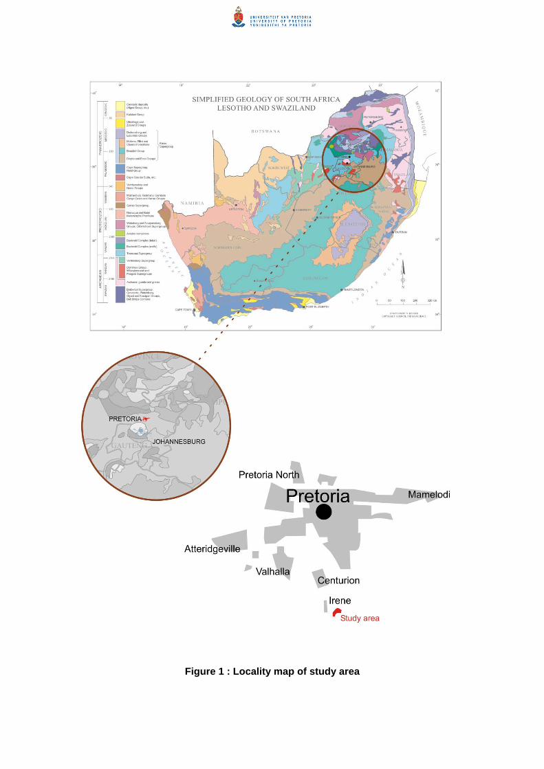
Figure 1 : Locality map of study area
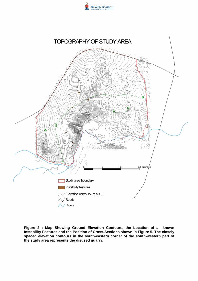
Figure 2 : Map Showing Ground Elevation Contours, the Location of all known Instability Features and the Position of Cross-Sections shown in Figure 5. The closely spaced elevation contours in the south-eastern corner of the south-western part of the study area represents the disused quarry.
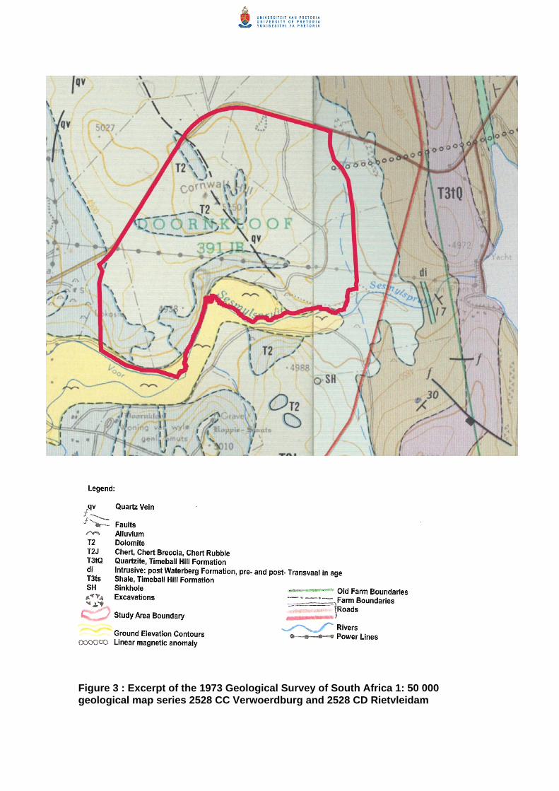
Legend: qv Quartz Vein
Faults Alluvium
T2 Dolomite T2J Chert, Chert Breccia, Chert Rubble T3tQ Quartzite, Timeball Hill Formation di Intrusive: post Waterberg Formation, pre- and post- Transvaal in age T3ts Shale, Timeball Hill Formation SH Sinkhole Old Farm Boundaries Excavations Farm Boundaries Roads Study Area Boundary
Rivers Ground Elevation Contours Power Lines Linear magnetic anomaly
Figure 3 : Excerpt of the 1973 Geological Survey of South Africa 1: 50 000 geological map series 2528 CC Verwoerdburg and 2528 CD Rietvleidam

Figure 4 : Excerpt of Council for Geoscience unedited and unpublished 1:10 000 geology sheets 2528 CC 15 Irene and 2528 CD 11 Rietvlei, used for the compilation of as yet unprepared 1:50 000 map. Faint numbers refer to GIS codes used in compiling and digitizing maps. Penciled in boundaries unstitched and sheets prepared by different geologists in different years. Map shows extensive disturbance of ground since 1973 (Figure 3).

W E
Figure 5 : Idealized Cross-Sections constructed using borehole information and observations at surface. Note the correlation between bedrock topography and gravity anomaly in Section A-B. Bedrock is generally deep on the gravity low anomalies and shallow on the gravity high anomalies. Although the presence of thick and continuous Karoo material was initially thought to exist, borehole information together with the bedrock topography map (Figure 8) and careful construction of sections such as these, ruled out the presence of large valleys infilled with Karoo age material and instead present infill material more likely to be much older (compact chert, locally brecciated). Initially the shallow dolomite in the south-western part of the study area was considered to be a near-continuous mass of rock. More detailed work revealed this only to be the case in isolated pockets, weathering most likely having been influenced greatly by joint patterns. Where fracturing of the rock is more intense, deeper leaching is likely to have occurred. Cross-sections E-F and C-D present idealized profiles in relation to inherent risk classes deemed appropriate based on individual boreholes. Evident in these sections is the high risk associated with shallow dolomite. See location of Cross-Sections in Figure 2.


Figure 6 : Stratigraphy of South Africa (courtesy Council for Geoscience)
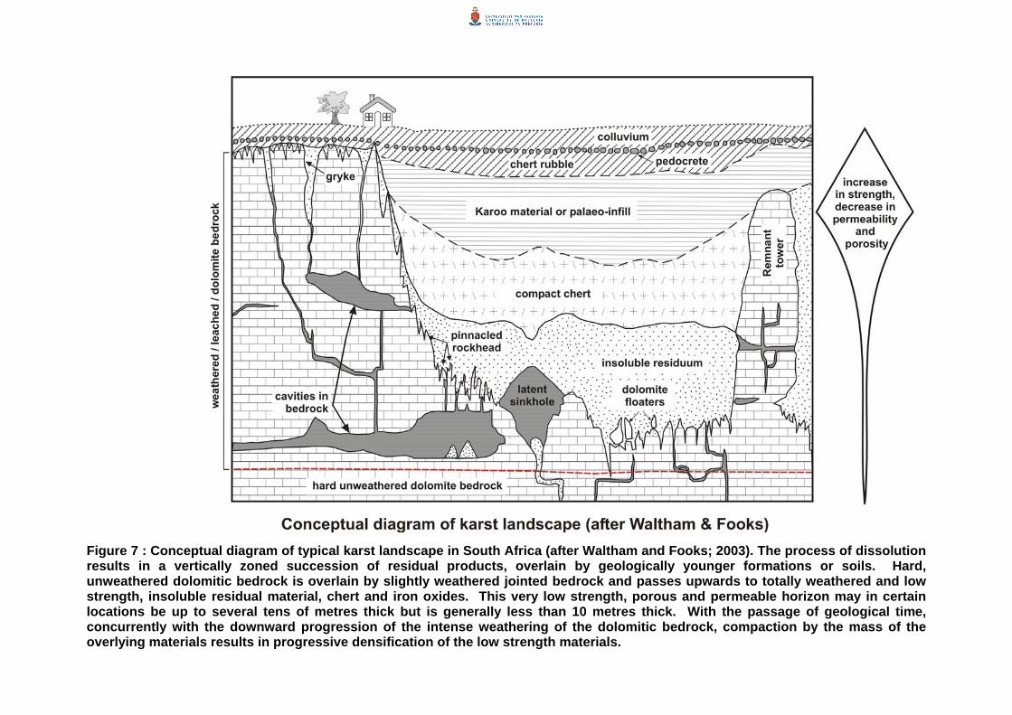
Figure 7 : Conceptual diagram of typical karst landscape in South Africa (after Waltham and Fooks; 2003). The process of dissolution results in a vertically zoned succession of residual products, overlain by geologically younger formations or soils. Hard, unweathered dolomitic bedrock is overlain by slightly weathered jointed bedrock and passes upwards to totally weathered and low strength, insoluble residual material, chert and iron oxides. This very low strength, porous and permeable horizon may in certain locations be up to several tens of metres thick but is generally less than 10 metres thick. With the passage of geological time, concurrently with the downward progression of the intense weathering of the dolomitic bedrock, compaction by the mass of the overlying materials results in progressive densification of the low strength materials.

1 2
Figure 8 : Surfer® plot of dolomite bedrock topdirection with 30 % tilt. The ka ography is s1 has a north-east orientation and lies to the eawith a northwest-southeast orientation, with theportion of the ground topographic ridge lying toeast and west with a relatively lower ridge extenmarked by extensive rock outcrop between bore
34
1 Dolomite bedrock highridge
2. Narrow low trough 3. Isolated sub-basin 4. Deep basin
ography (bedrock elevation contours in metres above mean sea level) in east-west ignificantly different from the ground topography presented in Figure 2.
rst topst of boreholes 61 and 47. In contrast the ground topography presents a high ridge ridge passing to the east of borehole 47 and west of borehole 50 with the northern the west of the cluster of boreholes 5, 1 and F. 1 drops to a plateau-like area to the ding to the southeast, partly isolating 3 from 4, as well as to the southwest, an area holes 40, 30 and 8.

Figure 9 : Surfer® plot of dolomite bedrock topography (as bedrock elevation contours) at 40 degree orientation with 8 % tilt. The plot shows how rugged the bedrock topography is with approximately 100 m difference between the highest ridge and the deepest basin. At least one peak or isolated pinnacle (perhaps a remnant tower, refer to Figure 7) is discernable to the left of the high ridge.

Figure 10 : Idealised diagram depicting typical shallow dolomite area incised with grykes and photo as an example

Figure 11 : Regional groundwater compartments and direction of groundwater flow (courtesy P Hobbs). The eastern part of the study area has been named the east Fountain Compartment and the western part of the study area is known as the East Doornkloof Compartment. The direction of the groundwater flow is indicated as well as the elevation of the water table.

Figure 12a: Hydrograph of borehole G 37836 located to the north of the Irene Dyke within the East Doornkloof Compartment (courtesy P Hobbs), showing the water level is relatively constant, only rising due to period of good rains. The graph also shows that the water level has not been lowered significantly (> 3 m) over the 17 year period. Refer to Figure 11.
STATION G37828
-50.0
-49.0
-48.0
-47.0
-46.0
-45.0
-44.0
-43.0
-42.0
-41.0
-40.0
Jul-8
7
Jan-
88
Jul-8
8
Jan-
89
Jul-8
9
Jan-
90
Jul-9
0
Jan-
91
Jul-9
1
Jan-
92
Jul-9
2
Jan-
93
Jul-9
3
Jan-
94
Jul-9
4
Jan-
95
Jul-9
5
Jan-
96
Jul-9
6
Jan-
97
Jul-9
7
Jan-
98
Jul-9
8
Jan-
99
Jul-9
9
Jan-
00
Jul-0
0
Jan-
01
Jul-0
1
Jan-
02
Jul-0
2
Jan-
03
Jul-0
3
Jan-
04
Date
Dep
th to
gro
undw
ater
res
t lev
el (m
bs)

Figure 12b: Hydrograph of borehole G37828 (courtesy P Hobbs) located to the south of the Irene Dyke within the East Doornkloof Compartment
STATION G37828
-50.0
-49.0
-48.0
-47.0
-46.0
-45.0
-44.0
-43.0
-42.0
-41.0
-40.0
Jul-8
7
Jan-
88
Jul-8
8
Jan-
89
Jul-8
9
Jan-
90
Jul-9
0
Jan-
91
Jul-9
1
Jan-
92
Jul-9
2
Jan-
93
Jul-9
3
Jan-
94
Jul-9
4
Jan-
95
Jul-9
5
Jan-
96
Jul-9
6
Jan-
97
Jul-9
7
Jan-
98
Jul-9
8
Jan-
99
Jul-9
9
Jan-
00
Jul-0
0
Jan-
01
Jul-0
1
Jan-
02
Jul-0
2
Jan-
03
Jul-0
3
Jan-
04
Date
Dep
th to
gro
undw
ater
res
t lev
el (m
bs)

Figure 13 : 1996 Bouguer anomaly map of the study area. The red areas represent areas of gravity high where dolomite bedrock is shallow, i.e. bedrock at and near surface, the blue areas represent areas of gravity low where dolomite bedrock is deep and the yellow and green areas represent transitional areas where bedrock depths vary, steepest bedrock gradients are anticipated where the contour lines are closely spaced.

Figure 14 : Regional gravity field. The first trend represents a general decrease in gravity values from north-east to south-west. Such a decrease is also discernible on the regional gravity data (Countrywide gravity survey undertaken by the Council for Geoscience).

Figure 15 : Observed gravity map with the location of the points where the occurrence and depth of dolomite were well constrained. Two of these points do not fall in the gravity survey area, but are important to constrain the polynomial surface. Table A lists the depths to dolomite at each of the points.
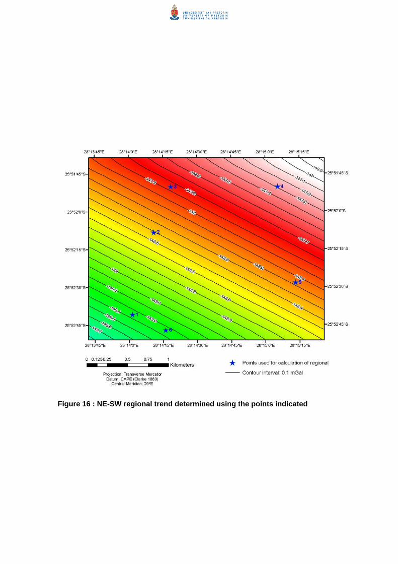
Figure 16 : NE-SW regional trend determined using the points indicated

Figure 17 : Residual gravity field after removal of the regional trend shown in Figure 16

Figure 18 : Third order polynomial surface representing the regional gravity field

Figure 19 : Residual gravity field calculated by subtracting the third order polynomial surface shown in Figure 18

Figure 20 : Depth to bedrock estimated from the residual gravity data shown in Figure 17. The purple areas show areas of shallowest bedrock and the red areas, show areas of deepest bedrock.

Figure 21 : Difference between the depth bedrock estimated from the polynomial surface fitting method and actual depth to dolomite. Points in red and orange show discrepancies of more than 21 to 99 m.

Figure 22 : Gradient map in y direction, produced from residual gravity shown in Figure 19. Warm colours (white, red and yellow) show areas of steepest bedrock with cool colours (blue and purple) showing areas of flattest gravity gradient. The areas of steepest gradients were plotted on the residual gravity map during the stability evaluation and guided the zonation.
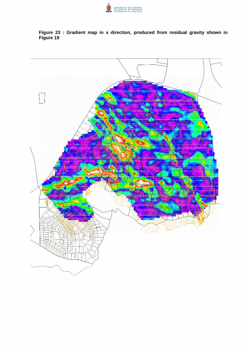
Figure 23 : Gradient map in x direction, produced from residual gravity shown in Figure 19

Figure 24 : Diagrammatic representation of gravity anomalies associated with type geological settings and possible risk classes

Figure 25 : Detailed mapping of a property exhibiting shallow dolomite with extensive outcrop (courtesy E Shedden)
Dolomite bedrock
Soil filled gryke

- 14 m line, i.e. bedrock at surface
Bedrock 100 m deep
Zero contour line
Figure 26 : Contour map of depth to dolomitic bedrock. 0-contour line represents bedrock at surface, as well as all negative numbers. Positive numbers refer to bedrock deeper than 1 m.

Figure 27 : Position of Boreholes, Test Pits, Dynamic Probe Super Heavy tests or surface mapping surveys in the study area

Areas excluded due
to poor spread ofborehole information
Smaller areas of shallowdolomite excluded in thefinal zonation
Figure 28 : Preliminary Zonation map based on isopach map of estimated depth to bedrock (Figure 26). This map shows the areas were bedrock is anticipated to be shallower than 8 m depth in blue and where bedrock is deeper than 8 m in red. This distinction has been useful in identifying the potential shallow dolomite bedrock areas. It was decided to ignore smaller zones of shallow dolomite. Two areas presented too few boreholes to confirm the presence of shallow bedrock and were also excised.

Figure 29 : Risk Zonation attempt of 1997 in comparison to 2005 evaluation. The first attempt sought to micro zone based on limited boreholes, while the second attempt seeks to zone more broadly with extensive borehole information. The first attempt identifies considerable land suitable for development, while the second attempt deems very little of the study area suitable for development.

Table A : Depth to dolomite at the points indicated in Figure 15
Point Depth to dolomite (m)
1 15 2 15 3 14 4 13 5 13 6 11 7 8 8 6 9 5 10 4 11 4 12 3 13 13 14 6 15 5 16 6 Table B : Observed gravity values and values calculated using Equation 2.1 at the points indicated in Figure 15 Point Easting (m) Northing (m) Observed
Bouguer Anomaly value (mGal)
Calculated gravity value (mGal)
Residual (mGal)
1 -76799.58 -2863310.48 -149.27 -149.39 -0.15 2 -76540.11 -2862305.00 -148.25 -148.43 -0.18 3 -76332.38 -2861747.20 -148.15 -147.87 0.28 4 -75023.76 -2861742.69 -147.01 -147.30 -0.29 5 -74802.10 -2862914.23 -148.40 -148.19 0.21 6 -76391.25 -2863499.21 -149.24 -149.37 -0.13 Table C : Densities measured for the overburden in borehole N DEPTH (m)
DENSITY (kg/m3)
AVERAGE DENSITY (kg/m3)
DESCRIPTION
3 2 593 6 2 583 8 2 538
2 572
Chert
9 1 567 10 1 488 12 1 619 14 1 572 15 1 710 16 1 390 17 1 817 18 1 592 19 1 630 20 1 754 21 1 730 22 1 761 23 1 782 24 1 764
1 655
Sand

Table D : Typical site conditions for inherent risk low, medium and high (Buttrick et al., 1995)
Inherent Risk
Typical site conditions
Low
The profile displays no voids. No air loss or sample loss is recorded during drilling operations. Either a very shallow water table or a substantial horizon of materials with a low potential susceptibility to mobilisation may be present within the blanketing layer (e.g. continuous intrusive features or shale material). Depth to potential receptacle is typically great and the nature of the blanketing layer is not conducive to mobilisation.
Medium This type of profile is characterised by an absence of substantial ‘protective’ horizon and has a blanketing layer of materials potentially susceptible to mobilisation by extraneous mobilisation agencies. The water table is below the blanketing layer.
High
The blanketing layer of the high risk profile reflects a great susceptibility to mobilisation. A void may be present and is interpreted to be very likely, within the potential development space, indicating that the process of sinkhole formation has already started. Boreholes may register large cavities, sample loss, air loss, etc. Convincing evidence exists of cavernous subsurface conditions which will act as receptacles. The water table is below the blanketing layer. In a dewatering situation, the lowering of a shallow groundwater level would obviously increase the risk of mobilisation.
Table F : Guideline residential development densities for various inherent risk class areas (Council for Geoscience, 2004)
Council for Geoscience guideline on maximum densities**
Risk class Residential type and density 1 Residential, including cluster development, high rise (60 u/ha) 2 Residential, including cluster development, high rise (40 u/ha)
2 (5) Selected residential -gentleman’s estates, cluster developments in new towns. High rise (30 to 35 u/ha)
3 ( a ) Selected residential, up to 18 u/ha (550 m2 minimum stands) 3 ( b ) Selected residential, up to 10 u/ha (1000 m2 minimum stands)
4 Selected residential, up to 18 u/ha (550 m2 minimum stands) 5 (3) or 3 (5) Selected residential, up to 10 u/ha (1000 m2 minimum stands)
5 (6) No residential development. However in case of very large stands (4000m2 or >) identify a suitable footprint area (risk class 4 or better OR 5(3))
6 or 6 (5) 7 8
4/5/6/7 (transition zones) Ass
ocia
ted
with
ent
ire z
one
and
not s
ingl
e bo
reho
le
No residential development
** Conditional to the following, to bring development to acceptable development risk: (a) Implementation of a specific risk management plan for the development (b) Existence of a working Regional Risk Management Plan (Local Authority) (c) Confirmation of stability zones by Competent Person during construction (d) Proper project management and supervision of construction work by a Competent Person (including
laying of wet-services) (e) Implementation and supervision of appropriate founding solution
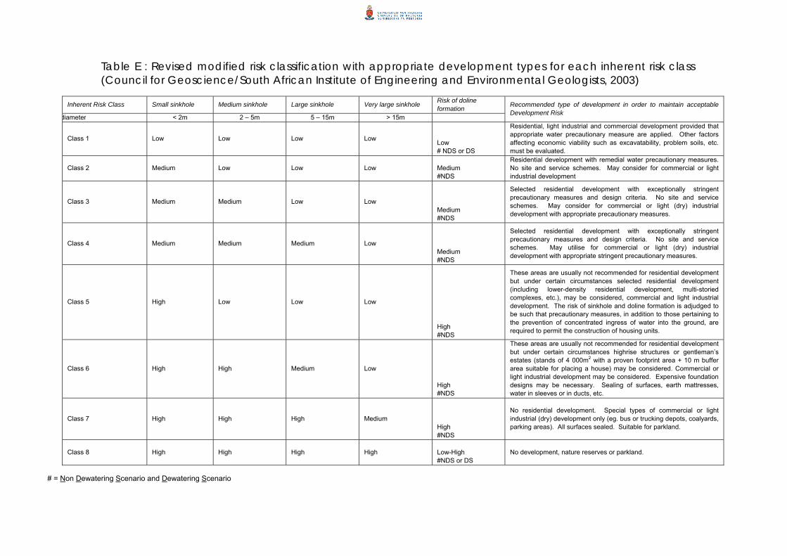
Table E : Revised modified risk classification with appropriate development types for each inherent risk class (Council for Geoscience/South African Institute of Engineering and Environmental Geologists, 2003)
Inherent Risk Class Small sinkhole Medium sinkhole Large sinkhole Very large sinkhole Risk of doline
formation diameter < 2m 2 – 5m 5 – 15m > 15m
Recommended type of development in order to maintain acceptable Development Risk
Class 1 Low Low Low Low
Low # NDS or DS
Residential, light industrial and commercial development provided that appropriate water precautionary measure are applied. Other factors affecting economic viability such as excavatability, problem soils, etc. must be evaluated.
Class 2 Medium Low Low Low Medium #NDS
Residential development with remedial water precautionary measures. No site and service schemes. May consider for commercial or light industrial development
Class 3 Medium Medium Low Low
Medium #NDS
Selected residential development with exceptionally stringent precautionary measures and design criteria. No site and service schemes. May consider for commercial or light (dry) industrial development with appropriate precautionary measures.
Class 4 Medium Medium Medium Low
Medium #NDS
Selected residential development with exceptionally stringent precautionary measures and design criteria. No site and service schemes. May utilise for commercial or light (dry) industrial development with appropriate stringent precautionary measures.
Class 5 High Low Low Low
High #NDS
These areas are usually not recommended for residential development but under certain circumstances selected residential development (including lower-density residential development, multi-storied complexes, etc.), may be considered, commercial and light industrial development. The risk of sinkhole and doline formation is adjudged to be such that precautionary measures, in addition to those pertaining to the prevention of concentrated ingress of water into the ground, are required to permit the construction of housing units.
Class 6 High High Medium Low
High #NDS
These areas are usually not recommended for residential development but under certain circumstances highrise structures or gentleman’s estates (stands of 4 000m2 with a proven footprint area + 10 m buffer area suitable for placing a house) may be considered. Commercial or light industrial development may be considered. Expensive foundation designs may be necessary. Sealing of surfaces, earth mattresses, water in sleeves or in ducts, etc.
Class 7 High High High Medium
High #NDS
No residential development. Special types of commercial or light industrial (dry) development only (eg. bus or trucking depots, coalyards, parking areas). All surfaces sealed. Suitable for parkland.
Class 8 High High High High Low-High #NDS or DS
No development, nature reserves or parkland.
# = Non Dewatering Scenario and Dewatering Scenario

Optimal borehole densities Inherent Risk
Class Maximum number of stands per representative borehole Comment
1 40 Homogenous conditions over larger area 2 20 Homogenous conditions over larger area 3 ( a ) 4 - 3 ( b ) 2 - 4 6 - 5 1 Prove suitability for proposed structure 6 Not applicable Housing not considered 7 Not applicable Housing not considered 8 Not applicable Housing not considered
Table G : Optimal borehole densities for various inherent risk class areas (Council for Geoscience, 2004)
22850 13850 22850 20000
66050
255200
0
50000
100000
150000
200000
250000
300000
Rands
Feasibility Phase 1 Feasibility Phase 1and 2
Phase 1, 2 andDesign Phase
Investigative Phase
Comparison of investigation costs (excluding professional fees)
inherent risk class 2inherent risk class 3 and 5
Table I : Comparison of investigation costs for homogenous conditions (e.g. risk class 2) versus heterogeneous conditions (e.g. risk classes 3 and 5) at various investigative phases
Maximum diameter of surface manifestation (dimension: metres)
Terminology
<2 Small sinkhole 2-5 Medium-size sinkhole
5-15 Large sinkhole >15 Very large sinkhole
Table J : Suggested classification of sinkholes in terms of size (Buttrick and Van Schalkwyk, 1995)

Table H : Building classes associated with inherent risk classes (SANS 10400-B) and Occupancy or Building Classification (SANS 10400-A)
Building classes Inherent risk class All classes 1 A, B (light only), C, D (light (dry) only), E, F, G, H, J 2 A, B (light only), C, D, (light (dry) only), E, F, G, H, J 3 A, B (light only), C, D (light (dry) only), E, F, G, H, J 4 A, B (light only), C, D (light (dry) only), E (if no safer alternative available), F, G, H (depending upon densities and mitigation measures that are adopted.), J
5
A5, B (light only), D (light (dry) only), G1 (with appropriate remedial measures), J 6 J3, J4 7 No classes 8
Class of occupancy or building
Occupancy
A1 A2 A3 A4 A5
Entertainment and public assembly Occupancy where persons gather to eat, drink, dance or participate in other recreation Theatrical and indoor sport Occupancy where persons gather for the viewing of theatrical, operatic orchestral, choral, cinematographical or sport performances. Places of instruction Occupancy where school children, students or other persons assemble for the purpose of tuition or learning. Worship Occupancy where persons assemble for the purpose of worshipping. Outdoor sport Occupancy where persons view outdoor sports events.
B1 B2 B3
High risk commercial service Occupancy where a non-industrial process is carried out and where either the material handled or the process carried out is liable, in the event of fire, to cause combustion with extreme rapidity or give rise to poisonous fumes, or cause explosions. Moderate risk commercial service Occupancy where a non-industrial process is carried out and where either the material handled or the process carried out is liable, in the event of fire, to cause combustion with moderate rapidity but is not likely to give rise to poisonous fumes, or cause explosions Low risk commercial service Occupancy where a non-industrial process is carried out and where neither the material handled nor the process carried out falls into the high or moderate risk category.
C1 C2
Exhibition hall Occupancy where goods are displayed primarily for viewing by the public. Museum Occupancy comprising a museum, art gallery or library.

Class of occupancy or building
Occupancy
D1 D2 D3 D4
High-risk industrial Occupancy where an industrial process is carried out and where either the material handled or the process carried out is liable, in the event of fire, to cause combustion with extreme rapidity or give rise to poisonous fumes, or cause explosions. Moderate-risk industrial Occupancy where an industrial process is carried out and where either the material handled or the process carried out is liable, in the event of fire, to cause combustion with moderate rapidity but is not likely to give rise to poisonous fumes, or cause explosions. Low-risk industrial Occupancy where an industrial process is carried out and where neither the material handled nor the process carried out falls into the high or moderate risk category Plant room Occupancy comprising usually unattended mechanical or electrical services necessary for the running of a building.
E1 E2 E3
Place of detention Occupancy where people are detained for punitive or corrective reasons or because of their mental condition Hospital Occupancy where people are cared for or treated because of physical or mental disabilities and where they are generally bed-ridden Other institutional (residential) Occupancy where groups of people who either are not fully fit, or who are restricted in their movements or their ability to make decisions, reside and are cared for.
F1 F2 F3
Large shop Occupancy where merchandise is displayed and offered for sale to the public and the floor area exceeds 250 m² Small shop Occupancy where merchandise is displayed and offered for sale to the |public and the floor area does not exceed 250 m² . Wholesalers' store Occupancy where goods are displayed and stored and where only a limited selected group of persons is present at any one time.
G1
Offices Occupancy comprising offices, banks, consulting rooms and other similar usage.
H1 H2 H3 H4
Hotel Occupancy where persons rent furnished rooms, not being dwelling units. Dormitory Occupancy where groups of people are accommodated in one room. Domestic residence Occupancy consisting of two or more dwelling units on a single site. Dwelling house Occupancy consisting of a dwelling unit on its own site, including a garage and other domestic outbuildings, if any.
J1 J2 J3 J4
High-risk storage Occupancy where material is stored and where the stored material is liable, in the event of fire, to cause combustion with extreme rapidity or give rise to poisonous fumes, or cause explosions. Moderate-risk storage Occupancy where material is stored and where the stored material is liable, in the event of fire, to cause combustion with moderate rapidity but is not likely to give rise to poisonous fumes, or cause explosions. Low-risk storage Occupancy where the material stored does not fall into the high or moderate risk category. Parking garage Occupancy used for storing or parking of more than 10 motor vehicles.

Plate 1: Rock exposed in the study area with ‘Bread and Butter’ appearance of Eccles Formation (courtesy J Van Der Merwe)
Plate 2: Rehabilitation of an old sinkhole, placement of steel mesh (courtesy J Van Der Merwe)
Plate 3: Rehabilitation of an old sinkhole, infill of fine material and placement of concrete layer (courtesy J Van Der Merwe)
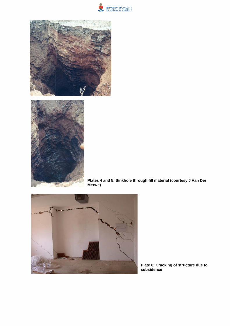
Plates 4 and 5: Sinkhole through fill material (courtesy J Van Der Merwe)
Plate 6: Cracking of structure due to subsidence

Plate 7: Grykes visible in disused quarry (courtesy J Van Der Merwe)
Plate 8: Fractured slot in disused quarry (courtesy J Van Der Merwe)

REFERENCES ADAMS, J.M., HINZE, W.J. 1990. The gravity-geologic technique of mapping buried bedrock topography. Geotechnical and Environmental Geophysics. Vol III, pp. 99 – 105. ALTERMANN, W. and NELSON, D.R. 1998. Basin analysis, sedimentation rates and regional correlations as implied by precise U-Pb zircon ages from volcanic sediments of the Neoarchean Campbellrand Subgroup of the Kaapvaal Craton. Sedimentary Geology. Vol 120/1-4, pp. 225-256. BEUKES, N.J. 1987. Facies relationships, depositional environments and diagenesis in a major early Proterozoic stromatolitic carbonate platform to basinal sequence, Campbellrand Subgroup, Transvaal Supergroup, South Africa. Sedimentary Geology. Vol 54, pp. 1-56. BEUKES, N.J. 1978. Die karbonaatgesteentes en ysterformasies van die Ghaap-Groep van die Transvaal Supergroep in Noord Kaapland. PhD dissertation, Rand Afrikaans University, Johannesburg, 580 pp. BOSCH, P.J.A. 2005. The Geology on portions of the farms Hartebeesfontein 17 JR and Sterkfontein 401 JR in the vicinity of Clayville, Benoni. Report number 2005-0197. 9 pp. BRINK, A.B.A. and PARTRIDGE, T.C. 1965. Transvaal karst: some considerations of the development and morphology, with special reference to sinkholes and subsidences on the Far West Rand. South African Geographical Journal. Vol 47, Dec 1965, pp. 11– 34. BUTTON, A. 1973. A regional study of the stratigraphy and development of the Transvaal basin in the eastern and north eastern Transvaal. Ph. D thesis, Department of Geology, University of Witwatersrand, South Africa. (Unpublished). BUTTRICK, D.B., VAN SCHALKWYK, A., KLEYWEGT R.J., WATERMEYER, R. 2002. Discussion on Proposed method for dolomite land hazard and risk assessment in South Africa. South African Institution of Civil Engineering Journal. Volume 44(3) 2002, pp. 25– 30. BUTTRICK, D.B., VAN SCHALKWYK, A., KLEYWEGT R.J., WATERMEYER, R. 2001. Proposed method for dolomite land hazard and risk assessment in South Africa. South African Institution of Civil Engineering Journal. Volume 43(2) 2001, pp. 27– 36. BUTTRICK, D.B., and VAN SCHALKWYK, A. 1995. The method of scenario supposition for stability evaluation of sites on dolomitic land in South Africa. South African Institution of Civil Engineering Journal. Fourth Quarter 1995, pp. 9– 14. CATUNEANU, O., and ERIKSSON, P.G. 1999. The sequence stratigraphic concept and the Precambrian rock record: an example from the 2.7 Ga Transvaal Supergroup, Kaapvaal craton. Precambrian Research. Volume 97 1999, pp. 215-251. CLENDENIN, C.W. 1989. Tectonic influence on the evolution of the early Proterozoic Transvaal Sea, southern Africa. PhD dissertation, University of Witwatersrand, Johannesburg, 367 pp. COUNCIL FOR GEOSCIENCE/SOUTH AFRICAN INSTITUTE OF ENGINEERING AND ENVIRONMENTAL GEOLOGISTS. 2003. Guideline for engineering-geological characterisation and development of dolomitic land. Council for Geoscience Publication, 66 pp. COUNCIL FOR GEOSCIENCE. 2006. Determining a regional field for gravity data collected at Cornwall Hill, Pretoria. Council for Geoscience Internal Report 2006-0178, 10 pp. DEPARTMENT OF PUBLIC WORKS. 2003. Appropriate Development of Infrastructure on dolomite: Guidelines for Consultants. PW344. 163 pp. ERIKSSON, P.G. and ALTERMANN, W. 1998. An overview of the geology of the Transvaal Supergroup dolomites (South Africa). Environmental Geology. Vol 36, pp. 179-188.

ERIKSSON, P.G., ALTERMANN, W., CATUNEANU, O., VAN DER MERWE, R., BUMBY, A.J. 2001. Major influences on the evolution of the 2.67-2.1 GA Transvaal basin, Kaapvaal craton. Sedimentary Geology. Vol 141-142. pp. 205-231. ERIKSSON, P.G., AND RECZKO, B.F.F. 1995. The sedimentary and tectonic setting of the Transvaal Supergroup floor rocks to the Bushveld Complex. Journal of African Earthsience. Vol 21. pp. 477-504. ERIKSSON, K.A. and WARREN, J.K., 1983. A palaeohydrologic model for early Proterozoic dolomitization and silicification. Precambrain Research, Vol 21, pp. 299-321. ENSLIN, J.F. and SMIT, P.J. 1955. Geophysical surveys for foundations in South Africa with special reference to the sinkholes in the dolomite south of Pretoria. Transactions of the South African Institution of Civil Engineering, Vol 5, No. 9. ENSLIN, J.F., KLEYWEGT, R.J., BEUKES, J.H.T., GORDON-WELSH, J.F. 1976. Artificial recharge of the dolomitic ground-water compartments in the Far West Rand Gold Fields of South Africa. International Association of Hydrological Science. Proceedings of the Anaheim Symposium, Publication No 121, Dec 1976, pp. 495– 506. HOBBS, P.J., 2004. Short letter report on the groundwater environment in the vicinity of portions 691 – 700 of the farm Doornkloof 391 JR, Gauteng Province. Hobbs Consulting Unpublished report 6 pp. HOBBS, P.J., 1988. Hydrogeology of the Verwoerdburg Dolomite Aquifer. Department of Water Affairs and Forestry Unpublished report, no GH3502. JENNINGS, J.E., BRINK, A.B.A., WILLIAMS, A.A.B. 1973. Revised guide to soil profiling for civil engineering purposes in Southern Africa. Transactions of the South African Institution of Civil Engineering, Vol 15, no 1, Jan 1973, pp. 3– 12. JENNINGS, J.E., BRINK, A.B.A., LOUW, A., GOWAN, G.D. 1965. Sinkholes and subsidences in the Transvaal dolomites of South Africa. Procedures of VI th International Conference on Soil Mechanics & Foundation Engineering, Montreal. Vol 1/11, 1965, pp. 51– 54. KLEYWEGT, R.J. and ENSLIN, J.F. 1973. The application of the gravity method to the problem of ground settlement and sinkhole formation in dolomite on the Far West Rand, South Africa. Symposium of the IAEC on sinkholes and Subsidence Engineering-geological problems related to soluble rock, Hannover, September, 1973. KLEYWEGT, R.J. and PIKE, D.R. 1982. Surface subsidence and sinkholes caused by lowering of the dolomitic watertable on the Far West Rand Gold Field of South Africa. Annal of Geological Survey of South Africa. Vol 16, pp. 77– 105. MARé, L.P., OOSTHUIZEN, B.C., TABANE, L.R., 2002. Physical Properties of South African rocks: South African Geophysical Atlas. Council for Geoscience, South Africa. Vol IV. MARTINI, J.E.J. 1987. Limestone and dolomite resources of the Republics of South Africa, Bophutatswana, Ciskei, Transkei and Venda: Handbook Geological Survey of South Africa, 9, 111 pp. MARTINI, J.E.J., ERIKSSON, P.G., SNYMAN, C.P. 1995. The early proterozoic Mississippi Valley-type Pb-Zn-F deposits of the Campbellrand and Malmani Subroups, South Africa. Miner Deposita. Vol 30. pp. 135-145. NATIONAL DEPARTMENT OF HOUSING. 2002. Geotechnical Site Investigations for Housing Developments (Project Linked Greenfield Subsidy Project Developments). Generic Specification GFSH-2. NATIONAL HOME BUILDERS REGISTRATION COUNCIL. 1999. Home Building Manual. Parts 1 and 2. February 1999. 138 pp. OBBES, A.M. 2000. The structure, stratigraphy and sedimentology of the Blackreef – Malmani – Rooihoogte succession of the Transvaal Supergroup southwest of Pretoria. Bulletin No 127. Council for Geoscience. 89 pp.

PARTRIDGE, T.C. AND MAUD, R.R. 1987. geomorphic evolution of southern Africa since the Mesozoic. South African Journal of Geology. Vol 90(2), pp. 179-208. SOUTH AFRICAN COMMITTEE FOR STRATIGRAPHY. 1980. Stratigraphy of South Africa, part 1. Lithostratigraphy of the republic of South Africa, South West Africa/Namibia, and the republics of Bophutathatswana, Transkei and Venda. Handbook of Geological Survey of South Africa. Vol 8. 690pp. SCHOPF, J.W. and KLEIN, C. 1992. The Proterozoic biosphere: A multidisciplinary study. Cambridge University Press, New York, 1348 pp. SOUTH AFRICAN BUREAU OF STANDARDS, STANDARDS SOUTH AFRICA. 2005. Draft: The Application of the National Building Regulations. Parts A: General Principles and Requirements, and B: Structural Design, and H: Foundations. SANS 10400. SWART, C.J.U. and VAN SCHALKWYK, A. 2001. Subsurface barriers for ground stabilization in dolomite areas near Carletonville, South Africa. Environmental Geology, 40(4/5), pp. 592– 601. TOENS, P.D. 1961. Precambrian dolomite and limestone of the Northern Cape Province. Ph.D. thesis, Department of Geology, University of Pretoria, South Africa. (Unpublished). VAN DER MERWE, J. 1996. Report on the dolomitic stability and foundation investigation carried out for the proposed Cornwall Hill development to be situated on portions 1 and 5 Doornkloof 391-JR, Centurion, Gauteng. (Unpublished). VAN DER MERWE, J. 1997. Revised report on the dolomitic stability and foundation investigation carried out for the proposed Cornwall Hill development to be situated on portions 1 and 5 Doornkloof 391-JR, Centurion, Gauteng. (Unpublished). VAN DER MERWE, J. 1997. Supplementary report on the dolomitic stability and foundation investigation carried out for the proposed Irene Extension 9 & 10 townships to be situated on portions 1 and 5 Doornkloof 391-JR, Centurion, Gauteng. (Unpublished). VAN DER MERWE, J. 1997. Revised report on the dolomitic stability and foundation investigation carried out for the proposed Cornwall Hill development to be situated on portions 1 and 5 Doornkloof 391-JR, Centurion, Gauteng. (Unpublished). WALRAVEN, F. and MARTINI, J.E.J. 1995. Zircon Pb-evaporation age determinations of the Oaktree Formation, Chuniespoort Group, Transvaal Sequence: Implications for the Transvaal-Griqualand West Basin correlations. WALTHAM, A.C. and FOOKES, P.G. 2003. Engineering Classification of karst ground conditions. Quarterly Journal of Engineering Geology and Hydrogeology. Volume 36 2003 pp.101-118. WARREN, J. 2000. Dolomite: occurrence, evolution and economically important associations. Elsevier Earth Science Reviews 52 (2000) pp. 1– 81. WILKINS, C. B. 1985. The geology of Post-Chuniespoort deposits in the Verwoerdburg area south of Pretoria with specific reference to engineering properties of the red soils. M.Sc thesis, Department of Geology, University of Pretoria, South Africa. (Unpublished). 99 pp.