Embed Size (px)
Citation preview

The GPS Satellite and Payload
Item Type text; Proceedings
Authors Codik, Andrew; Gronlund, Robert A.
Publisher International Foundation for Telemetering
Journal International Telemetering Conference Proceedings
Rights Copyright © International Foundation for Telemetering
Download date 18/05/2018 09:53:03
Link to Item http://hdl.handle.net/10150/609909
THE GPS SATELLITE AND PAYLOAD
Andrew Codik and Robert A. GronlundRockwell International Corporation
Satellite Systems Division12214 Lakewood Boulevard
Downey, California, USA 90241
ABSTRACT
The NAVSTAR/Global Positioning System Satellite is briefly outlined as is the techniquefor navigation using signals from such satellites. A description of the GPS navigationsubsystem with emphasis on its microprocessor and its interfaces and software routines isgiven.
INTRODUCTION
The NAVSTAR/Global Positioning System (GPS) satellite segment consists of a numberof satellites in 12 hour orbits at an altitude of 20, 183 Km (10,898 nautical miles). The firstNAVSTAR satellite was launched in February 1978, and the second in May 1978. The fullconstellation will consist of 24 satellites and will provide any user on or near Earthsimultaneous visibility of at least 6 satellites.
Navigation signals are transmitted by each satellite on two L-band frequencies (1575 MHzand 1227 MHz) to permit corrections to be made for ionospheric delays in signalpropagation time. These signals are modulated by two pseudorandom noise codes: P,which provides for precision measurements of pseudorange, and C/A, which provides foreasy acquisition of desired satellites. Data, consisting of satellite ephemerides, timecorrection coefficients and other useful information to the users, is modulo two added tothe pseudorandom codes.
The satellite L-band antenna radiates near uniform power to the users. Using signalsreceived from four satellites a user can make a position fix; within 10 meters in latitude,longitude and altitude. The amount of time required for a position fix depends on thesophistication of the receiving system and can vary from tens of seconds to severalminutes; the receiver can also provide the user vehicles velocity.
NAVIGATION TECHNIQUE
A user can determine his position in three dimensions if he can receive L-band signalsfrom four satellites. The precision of a user’s determination is a function of the geometryof the satellites used. Almanac information transmitted from the satellites is available tothe user for automatic or manual selection of the four satellites which present the bestgeometry and therefore allow the highest precision in position determination.
Performance of the navigation function requires synchronization of satellite clocks withGPS system time. An atomic frequency standard in each satellite monitored by the GPSControl Segment and clock correction data are provided to each satellite by the ControlSegment for transmission to users as digital correction coefficients. A user need not have aprecise frequency standard if he utilizes signals from four satellites, the fourth satellitepermits estimation of the user’s frequency standard bias. The four user position equationscontain four unknowns, three dimensions and the user’s frequency standard bias, and aresubject to simultaneous solution.
PHASE I SATELLITE
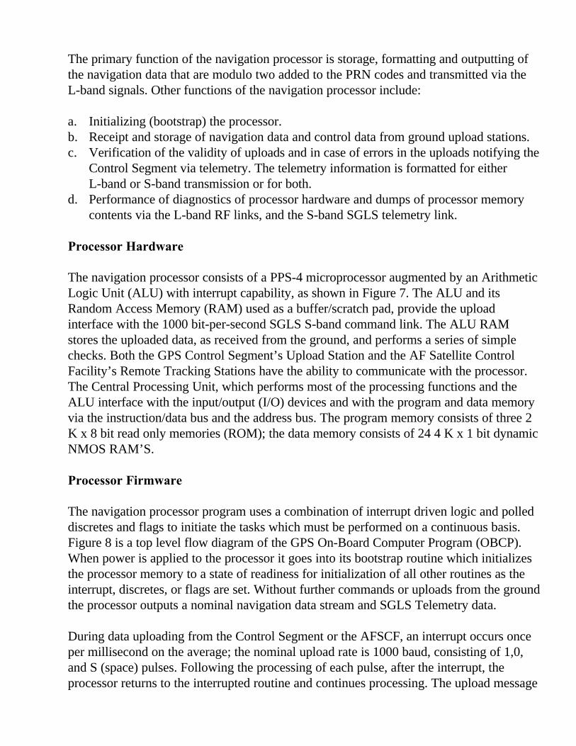
The GPS NAVSTAR satellites which are in orbit or being readied for launch are 3 axisstabilized with the navigation subsystem antenna pointing toward Earth. The satellitetracks the sun about the yaw axis, allowing the solar array panels to have a single degreeof freedom. This results in a beneficial thermal environment within the satellite. One sideof the satellite is exposed to the sun, and two sides always face deep space. Thermalcontrol of the satellite is simplified, the major heat producing components are mounted onthe deep space exposed sides, and control is accomplished by means of louvers andthermostatically controlled heaters. Figure 1 is an exploded view of the Phase I Satelliteand lists the salient features of the major satellite subsystems.
The Telemetry, Tracking and Command (TT&C) subsystem is fully compatible with theAir Force Space Ground Link System and also provides the uplink capability that is usedby the GPS Upload Station located at Vandenberg Air Force Base. The Upload Stationtransmits to the satellite the ephemerides and other data for use by the NavigationSubsystem’s Processor. The TT&C subsystem antennas provide omnidirectional coveragesince they are used for commanding and telemetry transmission during all phases of themission, including those during which the navigation subsystem antenna and forwardTT&C antennas are not pointed at Earth.
SATELLITE MISSION PAYLOAD
The mission payload of the NAVSTAR satellites is the Navigation Subsystem. It consistsof:
• Frequency Standards – 3 Rubidium atomic standards are provided, they are used in adormant redundancy configuration and are selected by ground command.
• Processor/Baseband – It generates the pseudorandom codes and modulates them withdigital data; it is internally doubly redundant and sections can be switched bycommand.
• The RF Equipment, consisting of carrier frequency synthesizers, modulotor/intermediate power amplifiers and high power amplifiers. The two L-band carriers arecombined in a diplexer/filter which in turn feeds the shaped beam antenna. The RFequipment is totally redundant and individually switchable except for the diplexer andthe antenna.
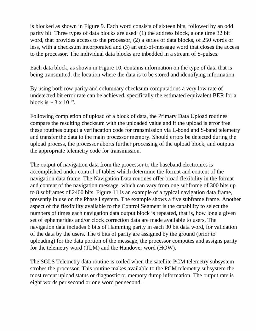
The Navigation Subsystem configuration is shown in Figure 2, and is representative of thefirst 3 NAVSTAR satellites. An additional cesium atomic frequency standard will beadded to satellites number 4 and subsequent during Phase I.
RF Section
The navigation subsystem RF section, as shown in Figure 2, derives its signals from the10.23 MHz output of the frequency standard. Two L-band carriers denoted L1 and L2 aresynthesized from this standard frequency. The L1 carrier, which has a frequency of1575.42 MHz is simultaneously modulated by the 10.23 MHz precision (P) pseudorandomnoise (PRN) code and the 1.023 MHz acquisition (C/A) PRN code in phase quadrature.The L2 carrier, at 1227.6 MHz, is modulated by either (selection is by ground command)the P code or the-C/A code. The P and C/A PRN codes are then exclusive-ored with the50 bit per second navigation data. The L-band carriers are amplified by the intermediatepower amplifiers (IPA) and high power amplifiers (HPA). The L1 HPA includes anincremental high power mode, which, when selected by command from the ground, resultsin an increased output of the C/A component.
Antenna
The intent of the NAVSTAR antenna is to provide equal power density to all terrestrialusers. This is accomplished with a shaped beam antenna: a quad helix encircled by a ringof eight helices. Figure 3 shows the antenna layout and the theoretical antenna patterncomponents and resultant pattern. The actual measured antenna pattern is shown inFigure 4.
The combined results of the actual antenna pattern and the predicted RF section outputsare plotted as a function of user antenna elevation angle and satellite antenna aspect angle,and are shown in Figure 5. Also shown are the specification requirements, which are thebases for user receiver design. The significant signal margins of the predicted results havebeen verified by measurements of NAVSTAR I AND NAVSTAR 2 using the CampParks, California, Air Force Facility.
Frequency Standard
The frequency standard is the heart of the Navigation Subsystem because it is the source ofthe GPS ranging function. The frequency standard-short term and long-term stabilitycharacteristics and predictability determine the basic navigation accuracy that can beachieved by the Global Positioning System; an uncertainty of one nanosecond in clock (orcode) phase is equivalent to approximately one foot of range uncertainty.
Figure 6 shows the regions of acceptable and unacceptable stability on an Allen Varianceplot, for the GPS Phase I frequency standard. Also shown in Figure 6 are actual laboratorymeasurements of Allen Variance for several production rubidium frequency standards usedon NAVSTAR satellites. Note that the actual frequency standard performance is betterthan the specification requirement by approximately an order of magnitude. This frequencystandard stability translates into potentially higher accuracy of position determination byGPS users. The frequency standard frequency is adjustable b ground command. The phase difference (integral of frequency difference) is adjusted by either changing the code stateof the baseband and/or modifying the clock correction coefficients transmitted in theNavigation Data message.
Digital Section
The digital section of the NAVSTAR satellite navigation subsystem consists of theProcessor/Baseband Assembly which includes 3 processors, each assembled on a twosided circuit board, and three sets of baseband electronics, each assembled on two boards.
The baseband electronics generates the 10.23 MHz precision (P) code and the 1.023 MHzacquisition (C/A) code and modulo two adds to these codes the 50 bits per secondnavigation data formatted by the navigation processor. Also, the baseband electronicsproduces the 19 bit time of week count (or Z-count) which repeats in seven days andincrements one binary count every 1.5 seconds. This Z-count is transferred to theprocessor every 1.5 seconds. The baseband electronics also has the capability of aligningthe P code and Z-count with respect to a ground based system standard via a commandmessage transferred from the processor.
The primary function of the navigation processor is storage, formatting and outputting ofthe navigation data that are modulo two added to the PRN codes and transmitted via theL-band signals. Other functions of the navigation processor include:
a. Initializing (bootstrap) the processor.b. Receipt and storage of navigation data and control data from ground upload stations.c. Verification of the validity of uploads and in case of errors in the uploads notifying the
Control Segment via telemetry. The telemetry information is formatted for eitherL-band or S-band transmission or for both.
d. Performance of diagnostics of processor hardware and dumps of processor memorycontents via the L-band RF links, and the S-band SGLS telemetry link.
Processor Hardware
The navigation processor consists of a PPS-4 microprocessor augmented by an ArithmeticLogic Unit (ALU) with interrupt capability, as shown in Figure 7. The ALU and itsRandom Access Memory (RAM) used as a buffer/scratch pad, provide the uploadinterface with the 1000 bit-per-second SGLS S-band command link. The ALU RAMstores the uploaded data, as received from the ground, and performs a series of simplechecks. Both the GPS Control Segment’s Upload Station and the AF Satellite ControlFacility’s Remote Tracking Stations have the ability to communicate with the processor.The Central Processing Unit, which performs most of the processing functions and theALU interface with the input/output (I/O) devices and with the program and data memoryvia the instruction/data bus and the address bus. The program memory consists of three 2K x 8 bit read only memories (ROM); the data memory consists of 24 4 K x 1 bit dynamicNMOS RAM’S.
Processor Firmware
The navigation processor program uses a combination of interrupt driven logic and polleddiscretes and flags to initiate the tasks which must be performed on a continuous basis.Figure 8 is a top level flow diagram of the GPS On-Board Computer Program (OBCP).When power is applied to the processor it goes into its bootstrap routine which initializesthe processor memory to a state of readiness for initialization of all other routines as theinterrupt, discretes, or flags are set. Without further commands or uploads from the groundthe processor outputs a nominal navigation data stream and SGLS Telemetry data.
During data uploading from the Control Segment or the AFSCF, an interrupt occurs onceper millisecond on the average; the nominal upload rate is 1000 baud, consisting of 1,0,and S (space) pulses. Following the processing of each pulse, after the interrupt, theprocessor returns to the interrupted routine and continues processing. The upload message
is blocked as shown in Figure 9. Each word consists of sixteen bits, followed by an oddparity bit. Three types of data blocks are used: (1) the address block, a one time 32 bitword, that provides access to the processor, (2) a series of data blocks, of 250 words orless, with a checksum incorporated and (3) an end-of-message word that closes the accessto the processor. The individual data blocks are inbedded in a stream of S-pulses.
Each data block, as shown in Figure 10, contains information on the type of data that isbeing transmitted, the location where the data is to be stored and identifying information.
By using both row parity and columnary checksum computations a very low rate ofundetected bit error rate can be achieved, specifically the estimated equivalent BER for ablock is ~ 3 x 10-19.
Following completion of upload of a block of data, the Primary Data Upload routinescompare the resulting checksum with the uploaded value and if the upload is error freethese routines output a verifacation code for transmission via L-bond and S-band telemetryand transfer the data to the main processor memory. Should errors be detected during theupload process, the processor aborts further processing of the upload block, and outputsthe appropriate telemetry code for transmission.
The output of navigation data from the processor to the baseband electronics isaccomplished under control of tables which determine the format and content of thenavigation data frame. The Navigation Data routines offer broad flexibility in the formatand content of the navigation message, which can vary from one subfrome of 300 bits upto 8 subframes of 2400 bits. Figure 11 is an example of a typical navigation data frame,presently in use on the Phase I system. The example shows a five subframe frame. Anotheraspect of the flexibility available to the Control Segment is the capability to select thenumbers of times each navigation data output block is repeated, that is, how long a givenset of ephemerides and/or clock correction data are made available to users. Thenavigation data includes 6 bits of Hamming parity in each 30 bit data word, for validationof the data by the users. The 6 bits of parity are assigned by the ground (prior touploading) for the data portion of the message, the processor computes and assigns parityfor the telemetry word (TLM) and the Handover word (HOW).
The SGLS Telemetry data routine is coiled when the satellite PCM telemetry subsystemstrobes the processor. This routine makes available to the PCM telemetry subsystem themost recent upload status or diagnostic or memory dump information. The output rate iseight words per second or one word per second.
The Read Z-Counter routine transfers the Z-count, the 19 bit count of GPS time, from thebaseband electronics to the processor every 1.5 seconds. This count repeats every sevendays and is used by the processor in several ways:
a) The 17 most significant bits are output in the second word of each navigation datasubframe.
b) The 3 least significant bits are used in the maintenance of navigation data outputsynchronization.
c) All 19 bits are used to time the performance of events including initiation of newnavigation data frame formats, code and time alignments, diagnostics and memorydumps and are stored in a designated location upon occurrence of an attitude controlsubsystem roll momentum dump.
d) The fourth through eleventh most significant bits are used to time tag the occurrence ofsatellite attitude control subsystem roll momentum dumps.
The Address Key Upload routine provides the AFSCF the capability for changing thecontent of a protected set of memory locations, in the processor main memory, in whichprimary upload address keys are stored. The Alternate Data Upload routine provides theAFSCF the capability of a low rote upload path via the command decoder.
The Roll Momentum Dump Report routine outputs, via the L-band links, the time ofoccurrence of roll momentum dumps.
The Code/Time Alignment Message routine transfers an 88 bit command message to thebaseband electronics which will change the Z-count and/or P-code output by the baseband,as commanded by the Control Segment. The realignment can be as small as one chip(~100 nanoseconds) or up to one week in length.
The Diagnostic and RAM Dump routines provide for diagnostics of the CPU logic, theALU and CPU RAMS and for dumps of the content of the ALU and CPU RAM. Resultsof these diagnostics and dumps may be via the TLM word in the navigation data subframeor via SGLS telemetry.
The Upload Address Verification routine formulates any of several upload status messageswhich inform the GPS Control Segment or AFSCF of errors in or success of uploads.
SUMMARY
The Phase I GPS satellites and ground segments have shown the feasibility of the GPSconcept. The navigation accuracy and operational flexibility of the system are being tested.Among the contributors to this operational flexibility testing are the satellite subsystemsincluding the navigation subsystem, switchable redundancy and the processor.
FIGURE 1. GPS SATELLITE
FIGURE 2. GPS NAVIGATION SUBSYSTEM
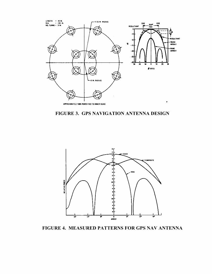
FIGURE 3. GPS NAVIGATION ANTENNA DESIGN
FIGURE 4. MEASURED PATTERNS FOR GPS NAV ANTENNA
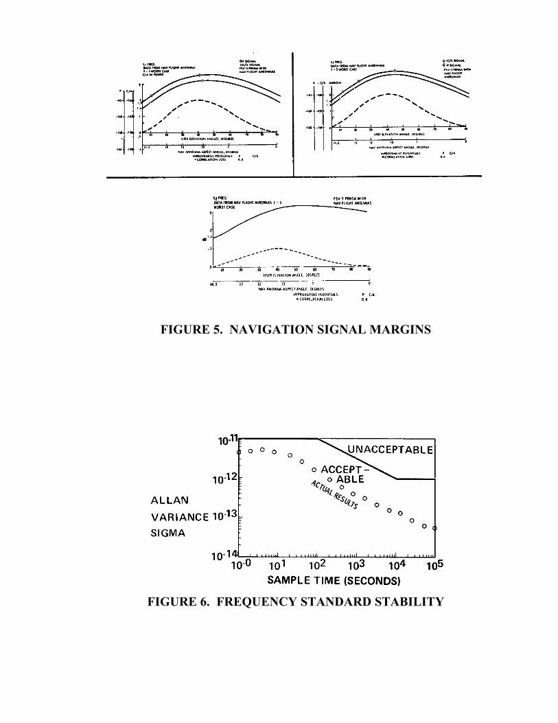
FIGURE 5. NAVIGATION SIGNAL MARGINS
FIGURE 6. FREQUENCY STANDARD STABILITY
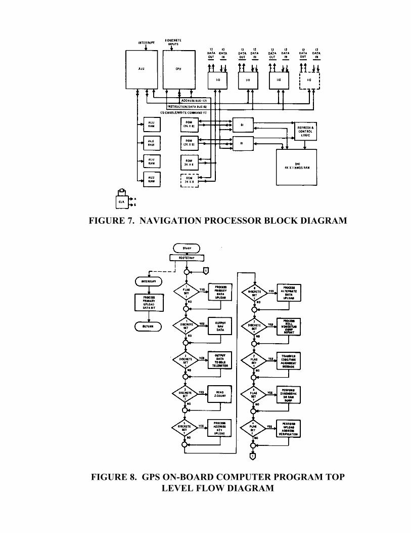
FIGURE 7. NAVIGATION PROCESSOR BLOCK DIAGRAM
FIGURE 8. GPS ON-BOARD COMPUTER PROGRAM TOPLEVEL FLOW DIAGRAM
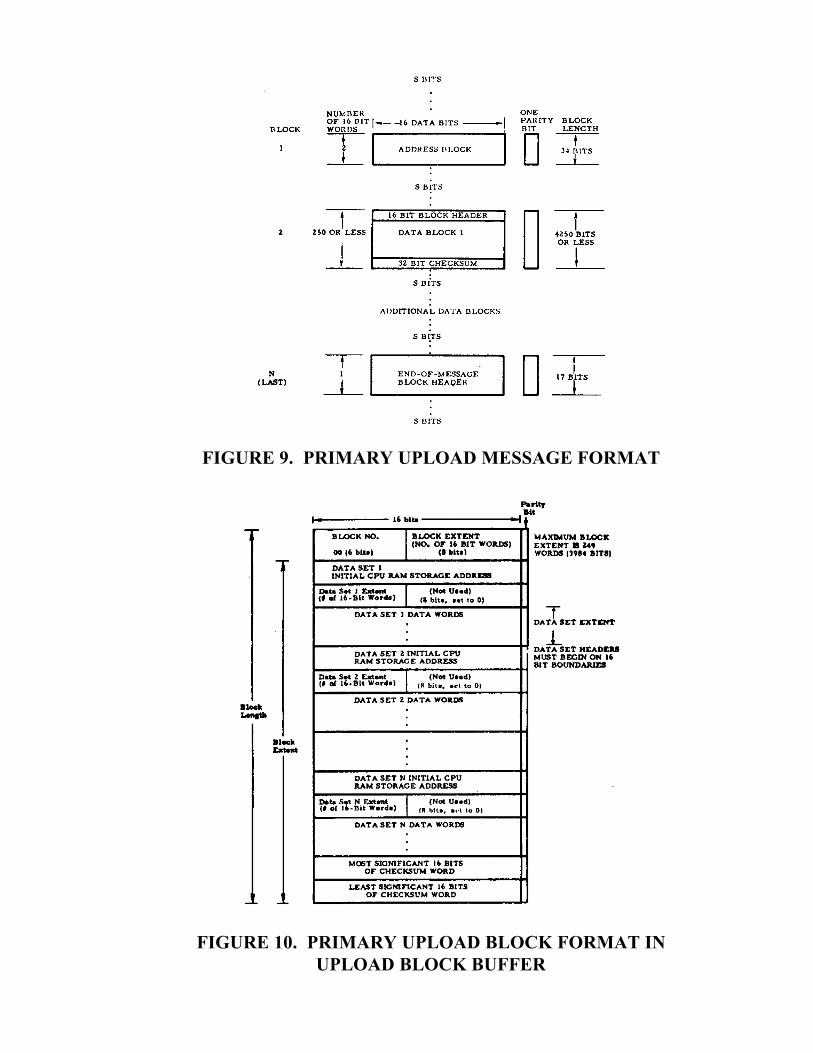
FIGURE 9. PRIMARY UPLOAD MESSAGE FORMAT
FIGURE 10. PRIMARY UPLOAD BLOCK FORMAT INUPLOAD BLOCK BUFFER
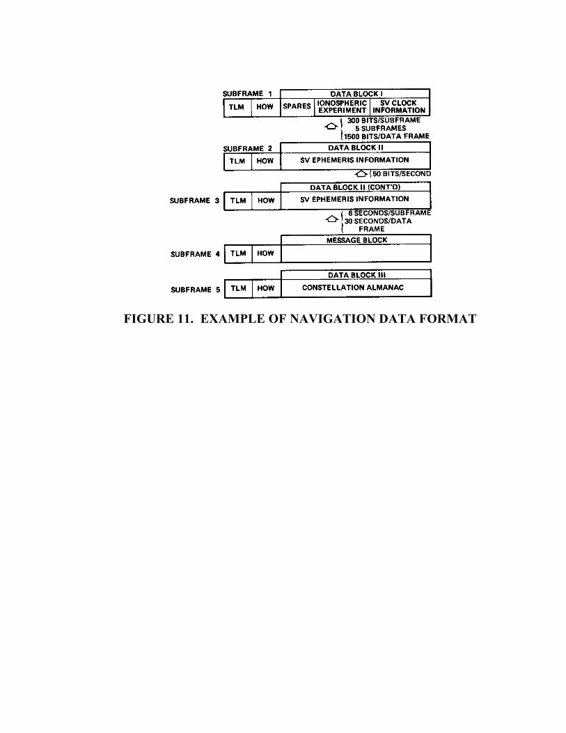
FIGURE 11. EXAMPLE OF NAVIGATION DATA FORMAT