Embed Size (px)
Citation preview
Rev. 16. 06/04
“THE HOOKER” OPERATING INSTRUCTIONS
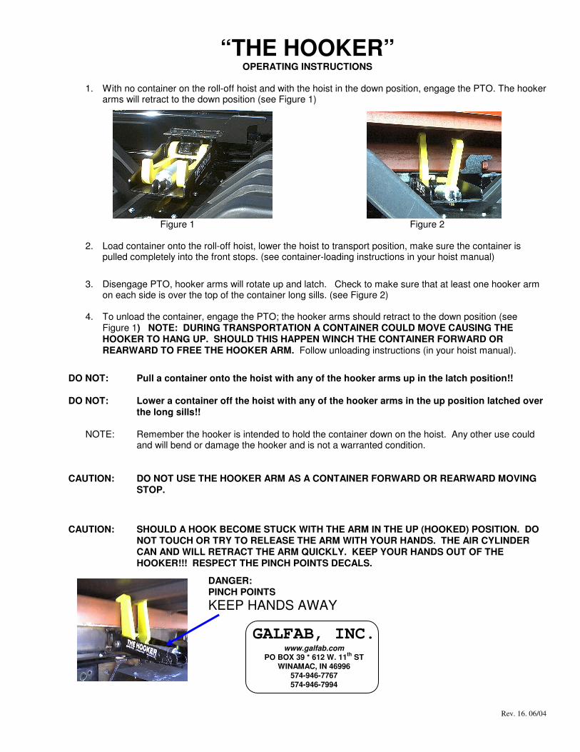
1. With no container on the roll-off hoist and with the hoist in the down position, engage the PTO. The hooker
arms will retract to the down position (see Figure 1)
Figure 1 Figure 2
2. Load container onto the roll-off hoist, lower the hoist to transport position, make sure the container is
pulled completely into the front stops. (see container-loading instructions in your hoist manual)
3. Disengage PTO, hooker arms will rotate up and latch. Check to make sure that at least one hooker arm
on each side is over the top of the container long sills. (see Figure 2)
4. To unload the container, engage the PTO; the hooker arms should retract to the down position (see Figure 1) NOTE: DURING TRANSPORTATION A CONTAINER COULD MOVE CAUSING THE HOOKER TO HANG UP. SHOULD THIS HAPPEN WINCH THE CONTAINER FORWARD OR REARWARD TO FREE THE HOOKER ARM. Follow unloading instructions (in your hoist manual).
DO NOT: Pull a container onto the hoist with any of the hooker arms up in the latch position!! DO NOT: Lower a container off the hoist with any of the hooker arms in the up position latched over
the long sills!!
NOTE: Remember the hooker is intended to hold the container down on the hoist. Any other use could and will bend or damage the hooker and is not a warranted condition.
CAUTION: DO NOT USE THE HOOKER ARM AS A CONTAINER FORWARD OR REARWARD MOVING STOP.
CAUTION: SHOULD A HOOK BECOME STUCK WITH THE ARM IN THE UP (HOOKED) POSITION. DO NOT TOUCH OR TRY TO RELEASE THE ARM WITH YOUR HANDS. THE AIR CYLINDER CAN AND WILL RETRACT THE ARM QUICKLY. KEEP YOUR HANDS OUT OF THE HOOKER!!! RESPECT THE PINCH POINTS DECALS.
GALFAB, INC. www.galfab.com
PO BOX 39 * 612 W. 11th ST WINAMAC, IN 46996
574-946-7767 574-946-7994
DANGER: PINCH POINTS KEEP HANDS AWAY
Rev. 16. 06/04
Maintenance, Disassemble and Reassemble Instructions for
“THE HOOKER” Maintenance
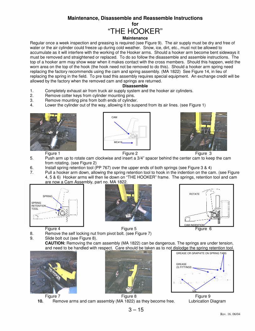
Regular once a week inspection and greasing is required (see Figure 9). The air supply must be dry and free of water or the air cylinder could freeze up during cold weather. Snow, ice, dirt, etc., must not be allowed to accumulate as it will interfere with the working of the Hooker arms. Should a hooker arm become bent sideways it must be removed and straightened or replaced. To do so follow the disassemble and assemble instructions. The top of a hooker arm may show wear when it makes contact with the cross members. Should this happen, weld the worn area on the top of the hook (the hook need not be removed to do this). Should a hooker arm spring need replacing the factory recommends using the cam and spring assembly. (MA 1822) See Figure 14, in lieu of replacing the spring in the field. To pre load this assembly requires special equipment. An exchange credit will be allowed by the factory when the removed cam and springs are returned.
Disassemble 1. Completely exhaust air from truck air supply system and the hooker air cylinders. 2. Remove cotter keys from cylinder mounting pins. 3. Remove mounting pins from both ends of cylinder. 4. Lower the cylinder out of the way, allowing it to suspend from its air lines. (see Figure 1)
Figure 1 Figure 2 Figure 3 5. Push arm up to rotate cam clockwise and insert a 3/4” spacer behind the center cam to keep the cam
from rotating. (see Figure 2) 6. Install spring retention tool (PP 767) over the upper ends of both springs (see Figure 3 & 4) 7. Pull a hooker arm down, allowing the spring retention tool to hook in the indention on the cam. (see Figure
4, 5 & 6) Hooker arms will then lie down on “THE HOOKER” frame. The springs, retention tool and cam are now a Cam Assembly, part no. MA 1822.
Figure 4 Figure 5 Figure 6 8. Remove the self locking nut from pivot bolt. (see Figure 7) 9. Slide bolt out (see Figure 8).
CAUTION: Removing the cam assembly (MA 1822) can be dangerous. The springs are under tension, and need to be handled with respect. Care should be taken as to not dislodge the spring retention tool.
Figure 7 Figure 8 Figure 9
10. Remove arms and cam assembly (MA 1822) as they become free. Lubrication Diagram
CAM
MC419
3 – 15
ROTATE
CAM INDENTION
SPRING
SPRING RETENTION TOOL
GREASE OR GRAPHITE ON SPRING TABS
GREASE (3) FITTINGS
OIL
R ev. 16. 06/04
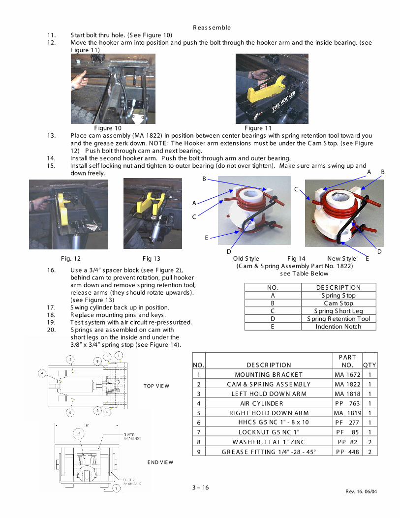
R eas s emble 11. S tart bolt thru hole. (S ee F igure 10)12. Move the hooker arm into pos ition and pus h the bolt through the hooker arm and the ins ide bearing. (s ee
F igure 11)
F igure 10 F igure 11 13. P lace cam as s embly (MA 1822) in pos ition between center bearings with s pring retention tool toward you
and the greas e zerk down. NOT E : T he Hooker arm extens ions mus t be under the C am S top. (s ee F igure12) P us h bolt through cam and next bearing.
14. Ins tall the s econd hooker arm. P us h the bolt through arm and outer bearing.15. Ins tall s elf locking nut and tighten to outer bearing (do not over tighten). Make s ure arms s wing up and
down freely.
16. Us e a 3/4” s pacer block (s ee F igure 2),behind cam to prevent rotation, pull hookerarm down and remove s pring retention tool,releas e arms (they s hould rotate upwards ).(s ee F igure 13)
17. S wing cylinder back up in pos ition.18. R eplace mounting pins and keys .19. T es t s ys tem with a ir circuit re-pres s urized.20. S prings are as s embled on cam with
s hort legs on the ins ide and under the3/8” x 3/4” s pring s top (s ee F igure 14).
NO. DE S C R IP T ION P AR T
NO. QT Y 1 MOUNT ING B R AC K E T MA 1672 1 2 C AM & S P R ING AS S E MB LY MA 1822 1 3 LE F T HOLD DOW N AR M MA 1818 1 4 AIR C Y LINDE R P P 763 1 5 R IG HT HOLD DOW N AR M MA 1819 1 6 HHC S G 5 NC 1" - 8 x 10 P F 277 1 7 LOC K NUT G 5 NC 1" P F 85 1
8 W AS HE R , F LAT 1” ZINC P P 82 2
9 G R E AS E F IT T ING 1/4" -28 - 45° P P 448 2
D
T OP V IE W
E ND V IE W
3 – 16
F ig. 12 F ig 13 Old S tyle F ig 14 New S tyle (C am & S pring As s embly P art No. 1822)
s ee T able B elow
NO. DE S C R IP T ION A S pring S top B C am S top C S pring S hort Leg D S pring R etention T ool E Indention Notch
D
C
C
A
A B
B
E
E
Rev. 16. 06/04
“THE HOOKER”
Installation Instructions, and Pneumatic Schematic
Where to locate ‘‘THE HOOKER’’ must be decided (i.e. behind the hinge, center of wheels, ability to remove
pivot bolt, etc.). In choosing the location, consider that the behind the hinge location may not work on short containers
and may not have clearance in the bumper and fender areas when the hoist is in the raised and lowered position. The
trunnion location may require relocating side rollers, or modifying fenders.
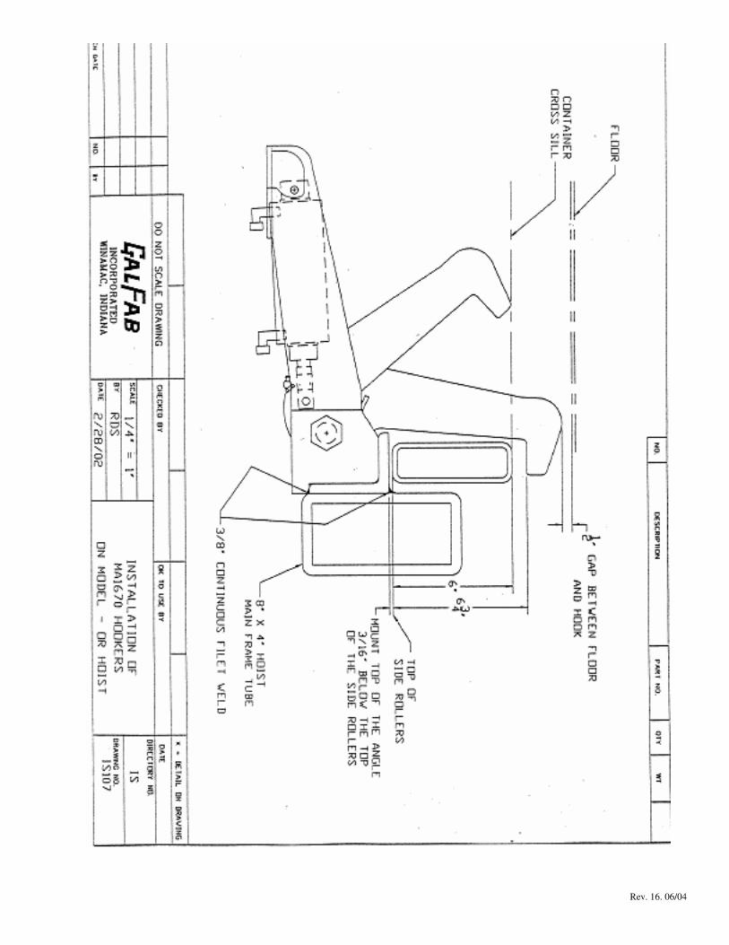
“THE HOOKER” mounting angle should be welded to the main frame of the hoist as shown on IS107. The top of
“THE HOOKER” mounting angle should be 3/16” below the top of the side rollers. Each set of hookers have the pivot
bolt installed in an opposite direction making them a pair. Mount “THE HOOKER” so that the pivot bolt can be
removed.
Weld “THE HOOKER” mounting angle to the main frame of the hoist with 3/8”continuous fillet welds across the
top and bottom. DO NOT WELD THE SIDES. DO NOT ALLOW SPRINGS TO BE DAMAGED WHEN
WELDING.
Hooker kits are supplied with valves for manual air shifted PTO’s. The factory recommends hooker controls
be integrated with PTO controls, i.e. when PTO is engaged, hold on arms are unlatched; when PTO is disengaged, hold
on arms are in latched position. Trucks with other than air shifted PTO’s (such as manual or hydraulic) may require
special valving or air supply (check with factory).
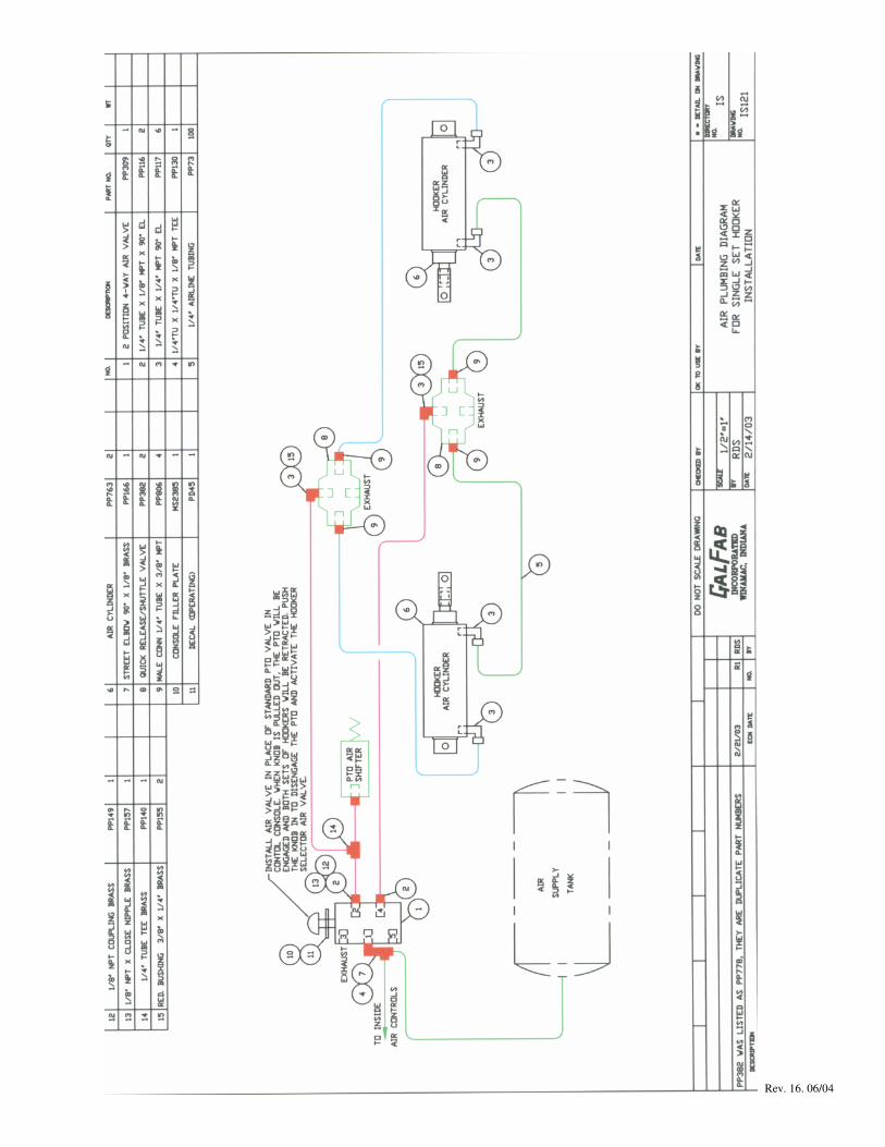
A 4-way air valve (item No. 1) must be used in lieu of the air control valve furnished with the P.T.O. The 4-
way air valve should be installed in the cab of the truck and the air lines plumbed, using brass fittings, as shown on the
attached IS121. Install the elbow (item No. 7) in the No. 1 port of the 4-way air valve (item No. 1). Attach the tee
(item No. 4) to the elbow. Connect a 1/4” air tube (item No. 5) from the tee to the in cab hoist controls and to the air
supply. Ports 3 and 5, on the 4-way air valve, are exhausted to atmosphere. Install the close nipple (item No. 13) to
port No. 2, on the 4-way air valve. Install coupling (item No.12) to the close nipple, attach an elbow (item No. 2),
using 1/4” air tube (item No. 5) connect this elbow to tee (item No. 14), connect this tee to the P.T.O. using 1/4” air
tube (item No. 5). Connect the air cylinder extend line to tee (Item No. 14) and attach the air tube to the supply port of
a quick release valve (item No. 8) using reducer (item No.15) and elbow (item No. 3). Attach elbow (item No. 2) to the
No. 4 port of the valve (item No.1) (this is the air cylinder retract port). Attach air tube (item no. 5) to the supply port
of the retract quick release valve (item No. 8) using reducer (item No. 15) and elbow (item No. 3). Using connectors
(item No.9) attach air tubes (item No. 5) to the DEL ports on both the quick release valves. (NOTE: The air quick
release valves should be located at the rear of the truck.) The four air tubes should bend around the hoist mainframe
hinge area and run along the mainframe to the “THE HOOKER” air cylinders. Attach air tubes (item No. 5) to the
cylinders using elbows (item No. 3). Be sure the extend port of both cylinders are attached to the extend quick release
valve and the retract port of both cylinders is attached to the retract quick release valve.
Grease all the grease zerks before using and once a week thereafter.
For Outside Rail Hoist
Rev. 16. 06/04
Rev. 16. 06/04