Embed Size (px)
Citation preview

HYDRAULICS BRANCH OFFICIAL FILE COPY
. 0 r\J
UNITED ·sTATES
DEPARTMENT OF THE INTERIOR
BUREAU OF R..::CLAMATION
BUR:'. .U OF R;�r,1 _ HYJ'1? iJJL IC L.t · - 1,
NOT 'l O LE -RE1V,OV .::,D l· itO,v1 .
THE HYDRAULIC DESIGN OF A CONTROL GATE FOR THE 1O2-INCH OU TLE TS IN
SHASTA DAM
CENTRAL VALLEY PROJECT- CALIFORNIA
Hydraulic Laboratory Report No. Hyd-201
BRANCH OF DESIGN AND CONSTRUCTION
DENVER, COLORADO
MARCH 31,1946

•
•
UNITF..D STATES DEPARTMENT OF THE INTERIOR
BUREAU OF RECLAMATION
Branch of Design and Construction Engineering and Geological Control and Research Division
Denver, Colorado March 31, 1946
Laboratory Report Noo 201 Hydraulic Laboratory Compiled by: Fo C. Lowe Reviewed by: Jo W. Ball
Subject: The hydraulic design of a control gate for the 102-inch outlets in Shasta Dam, Central Valley Project, California.
INTRODUCTION
The Problem
In each of the eighteen 102�inch outlets in Shasta Dam it was desirable to use a valve which could operate at any opening. Since the valve was to be placed in the conduit upstream from the exit, existing types could not be used, for they would be damaged by cavitationo Therefore, a new type of tube valve was developed. Four were built and jJ�stalled, but they were so expensive that a more economical control, a gate, was proposed for the fourteen remaining outlets. In December 1944, the hydraulic laboratory was assigned to assist the mechanical section j_n, the design of this control gate. The object of this assignment was to develop a gate which would operate satisfactorily at any opening, or a.t least be capable of satisfactory operation at the full open and closed positions.
The 102-inch Outlets in Shasta Dam
The Shasta Dam on the Sacramento River, 9 miles above Redding, California, is a multipurpose dam, It regulates the flow of the river for flood control, irrigation storage, and power generation. The release of water for flood storage evacuation and consumptive demand do1mstream will be primarily through the powerhouse turbines. Releases in excess of the capacity of the turbines will be made through eighteen 102-inch outlets placed at three elevations�four in the lower tier at elevation 742, eight in the :intermediate tier at elevation S42, and six in the upper tier at elevation 942, as shown in section and elevations of Figure 1.
The outlets, passing directly through the Dam to discharge upon the face of the spillway, are a distinctive type originally developed for Grand Coulee Dam as shown in Figure 2. The entrance of those outlets was formed by a circular bellmouth set flush with the upstream face of the Dam. The controls, located several diameters downstream, consisted of two ring�seal gates in tandem, the downstream gate for service and the upstream one for emergency use. Near the exit the conduit turned

.. ..
....
downward into a trough' which faired into the face of the spillway. A cone at the exit reduced the diameter from 102 inches to 93 inches to create back-pressure to compensate for the drop in elevation between the conduit and the exit •
The two ring-seal gates in tandem at Grand Coulee Dam were to be operated only at wide open or closed positions. No regulation of flow was contemplated, other than that which could be obtained by using the outlets in different tiers, for in the light of past experience successful regulation could not be obtained with a gate in the conduit upstream from the exit. The situation at Shasta Dam was different, however, as close regulation was desired. To accomplish this, it was essential that the controls be improved over types hithertofore used. Without exception, these controls, consisting of ring-seal, ring follower, and paradox gates, ensign valves, and needle valves� were being damaged in the field, largely through pitting by cavitation.1
Once it was fully realized that cavitation was the paramount source of trouble, the mechanical section and the hydraulic laboratory joined in an effort to correct the faults of existing controls; and to develop new designs in which cavitation would not persist. At the time preliminary designs of the 1O2-inch outlets in Shasta Dam were being made, successful efforts were being direc�ed towards revising the shape of the passage through needle valves. During the course of the needle valve studies a new type of control was introduced, a tube valve (Figure 3). This valve, fundamentally a needle valve with the downstream tip removed, was proposed for the outlets in Shasta Dam. To assure successful operation of the proposed valve, the design was developed through a series of hydraulic model studies. Upon obtaining a desirable design four units were installed in the lower outlets in Shasta Dam (elevation 742.0O)o However, these valves were expensive, and they could not be operated at certain openings since cavitation was indicated. A more economical control, a gate, was proposed for the remaining 14 outlets pending its development in the hydraulic laboratory.
Before commencing the discussion of the tests to design the gate, the subject of this repqrt, a sununary of the tube valve studies will be given, since those studies were precedent to the design of the control gate and .furnished important information for the later tests.
1/ For an outline of the performance of such controls see "High Pressure Reservoir Outlets" by Gaylord and Savage. See also Laboratory Report HYD 137, "Cavitation Experiences of the Bureau of Reclamation," January 5, 1943, by J.E. Warnock.
y Laboratory Report HYD 98. "Hydraulic Model Studies for the Design of Valves for Outlet Works Performed at Boulder Dam," August 1941, by N. G. Noonan, H. M. Martin, and D. J. Hebert.
2

The following section is taken from Laboratory Report RYD 180, 11Hydraulic Studies for the Design of the Tube Valves in the Outlets in Shasta Dam, 11
August 7, 1945, by D. J. Hebert.
Hydraulic Studies of the Proposed Tube Valve
"Since no previous studies of valves discharging in a. closed conduit were available, the hydraulic laboratory was assigned the problem of the investigation of the hydraulic characteristics. The scope of the laboratory studies was circumscribed by the request that they be made to determine a design of tube valve which will operate satisfactorily at all openings with aeration, if necessary. and with a sufficiently high coefficient of discharge that the downstream portion of the conduit would flow full at full valve opening. To insure against damage by pitting due to cavitation, it was assumed that at no point in the prototype valve and conduit should the pressure be less than 25 feet below atmospherico
Preliminary tests on the 1 to 17 model of the original tube valve design proved conclusively that a valve discharging into a closed conduit must be provided with adequate air relief for operation at partial openings and that the original design could not be revised to perform satisfactorily at any opening.
A new design of valve characterized by its long slim shape and referred to loosely as the 1 Shasta Tube Va.lve 1 was developed specifically for operation in a closed conduito This valve when fully opened had a discharge coefficient high enough to fill the conduit under pressure. Despit,e extensive development of air relief measures, a valve of this type located in the lower tier under maximum head would be inoperative over nearly 40 percent of its range of opening because of the presence of subatmospheric pressures conducive to cavitation erosion. For heads less than the maximum of 322 feet the inoperative range is reduced to some 7 percent for a head of 222 feet which corresponds to the head on the intermediate tier of valves for maximum reservoir surface elevation.
Model tests on a 20-inch diameter valve (1 to 5ol scale) of the Shasta 'rube Valve type were conducted in the Arizona valve house at Boulder Dam and the results confirmed those obtained in the tests made with the 6-inch diameter valve (1 to 17 scale) in the Denver laboratory. The quantity of air required to relieve the negative pressures created by the con= dition of a valve discharging.into a conduit was measured in both models and the -sizes of,air piping required to supply each prototype valve were determined by using the criterion that air velocities should not exceed 300 feet per ,second in the interest of quiet operation.
3

Another series of tests was conducted using two valves, a tube valve and a needle valve, which had been developed by a separate model study for free discharge conditions at Friant Dam. The tests proved that, with air relief provided at a point innnediately downstream from either of the valves, they were as satisfa,ctory at all openings, from the standpoint of pressures, for conduit operation as for free discharge operation. The only change due to operation of these valves in a conduit was a minor decrease in pressure at the end of the valves for supplying the required flow of air through the air relief piping. The maximum amount of air relief required for either valve was approximately equal to the amount required by the Shasta Tube Valve so the size of the air supply piping would be the same for all three valve designs.
The possibilities of damage to the portion of the metallined conduit downstream from the valve by corrosion due to the large amount of air mixed with the water at partial valve openings, which at times may reach as high as 215 percent more air than water, were not investigated in the studies described in this report. The accelerated corrosion which may occur is, however, believed to be a definite factor in any consideration of valves for operation in closed metal-lined conduits and a check of field conditions from time to time is recommended to establish its importance • 11
THE INVESTIGATION
Scope of Tests
Upon completion of model studies of the tube valve, four were placed in the lower outlets in Shasta Dam. In addition, there was installed in each of the 14 remaining outlets a bell-shaped segment of the valve body and a tore--shaped air vent as noted on Figure 3. When a more econqmical gate was proposed, as the control for the 14 outlets in which tube valves were not installed, the hydraulic laboratory was assigned to assist the mechanical design section of the Bureau to develop this gate through model tests. Although this gate must be placed in the outlets between the valve segment and the air vent, it was not necessary to consider these existing members unless they could be used to advantage. The main object was to obtain the hydraulic design of the gate itself. The salient features of the problem were that the gate would be placed in a conduit upstream from the exit, and that regulation of flow was desirable. If regulation were not possible the gate should, at least, operate satisfactorily at the wide open and closed positionso
The tests to design the gate were restricted to studies on small models which could be attached to a 6-:1.nch pipe, and on which it was possible to measure discharge, pressures, air demand, and to observe the
4

nature of the flow. The conditions observed in the models were inter� preted in prototype terms by the laws of hydraulic similitude to predict the prototype behavior. The criteria of design were simple. In previous tube valve tests the premise was that "at no point in the valve or conduit should the pressure be less than 25 feet of water below atmospheric," It was believed that this limitation was too lenient because of the possibility of a further reduction of pressure due to local L�perfections of the control and conduit forming the flow passage. In the design of the gate, therefore, it was desired that the pressure should not be lower than 15 feet below atmospheric. A third condition was that the hydraulic design of the gate lend itself so far as possible to a sim= ple, easily=built structure.
§.mmn�_lX of Testra
A 1:17 model of a gate patterned somewhat after conventional types was first. studied o Operation at the full open position was satisfactory ., for a smooth jet passed through the slot into the conduit downstream. At partial openings, however, the jet impinged into the slot fill:L1g it and the bonnet above, and blocking off the air vents. Undesirable flow conditions were observed and severe negative pressures were recorded, This original design would not have been satisfactory for reguJ.a.tion of flowo
The desirable features of a regulating gate �rere then formulated by drawing upon available sources of information. The :important charac� teristi�s included�
,.. .J. 0
I '+•
A simple rectangular leaf
A seal in the body of the gate to contact the leaf on its upstream face
A leaf with its upstream face machined to a smooth pla�e surface so that the seal in the gate frame contacts the leaf at all openings
A single air vent with as large a cross-section as practicable considering the structural restrictions imposed by existing construction
A flow of water through the gate and into the conduit downstream which would not impinge into the gate slot in such a manner as to fill the slot and prevent the air vent from functioning, or against the interior surfaces in such a manner as to create a region of intense nega=, tive pressure.
'l'he laboratory was concerned primarily with this last condition, for the first three considerations were essentially mechanical problems, and the location of an air vent was secondary to a basic design e
5

The shape of the jet which would exist under a gate of the type to be studied was observed on a simple model consisting of a sheet metal plate placed over the end of a pipe. With the pipe partially closed by this plate, the flow deflected downwards and spread sidewise to form a fan-shaped jet, unsuitable for discharging into a conduit. A sharpedged orifice was then placed at the end of the pipe over which the leaf moved. The resulting jet for any position of the leaf was comparatively level, compact, and adaptable for flow into a conduit.
·It was found possible to obtain a satisfactory gate design by expanding the conduit upstream from the orifice to at least lo2 times the orifice diameter. The bell-shaped upstream section of the Shasta Tube Valve, which had been installed in all of the outlets, was suitable for this expanding section, and was therefore incorporated in the proposed gate. The orifice was beveled at 45 degrees to permit a seal to be attached. The existing air pipes at the outlets in Shasta Dam were to be connected directly into the conduit and gate bonnet.
Through a series of tests to improve this proposed gate, the final design was developed (Figures 4 and 5). The model indicated that no pressure less than 3 feet below atmospheric will exist at any point in the gate or conduit immediately downstream. It was found that severe negative pressures did exist at the elbow where the conduit turned downward to fair into the face of the spillway; however, these tests were not concerned with that condition since the outlet conduits had been built.
Conclusions and Recommendations
This control gate for Shasta Dam has several unique features which lead the engineers of the Bureau to believe that it is a type with which regulation of flow in a closed conduit may be possible. Not only is the design desirable from a hydraulic viewpoint, but it is also desirable from structural and mechanical viewpoints because of its simplicity. The outstanding feature of the gate was the compact well-directed jet which could be obtained at any opening. fhis feature makes the gate adaptable not only for regulation of flow in a closed conduit but also for operation as a free discharge valve.
It was demonstrated that the gate could be u�ed for free discharge, either directing the jet into the air or down a spillway apron. A design was proposed which had the following features: The orifice diameter will be the same size as the conduit diameter. Beginning one conduit diameter upstream from the gate, the conduit would expand, increasing 20 percent when it reaches the gate. With these features positive pressures should exist at all points upstream from the orifice and the discharge capacity will be, when expressed as a coefficient of discharge, approximately 0.80, where the coefficient of discharge is C in the relation Q = C A/2gfi, where Q = discharge, A= the area of the conduit, and H = the total head measured one diameter upstream from the valve.
6
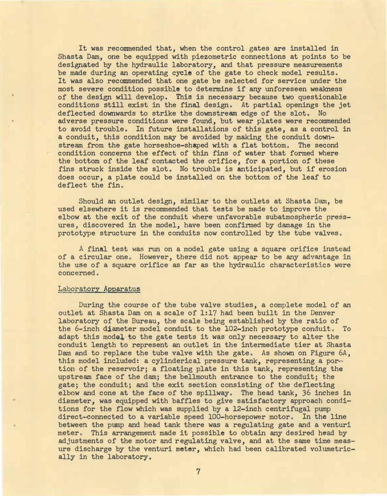
It was recommended that, when the control gates are installed in Shasta Dam, one be equipped with piezometric connections at points to be designated by the hydraulic laboratory, and that pressure measurements be made during an operating cycle of the gate to check model results. It was also recommended that one gate be selected for service under the most severe condition possible to determine if any unforeseen weakness of the design will develop. This is necessary because two questionable conditions still exist in the final design. At partial openings the jet deflected downwards to strike the downstream edge of the slot. No ad.verse pressure conditions were found, but wear plates were recommended to avoid trouble. In future installations of this gate, as a control in a conduit, this condition may be avoided by making the conduit do�nstream from the gate horseshoe-shaped with a flat bottom. The second condition concerns the effect of thin fins of water that formed where the bottom of the leaf contacted the orifice, for a portion of these fins struck inside the slot. No trouble is anticipated, but if erosion does occur, a plate could be installed on the bottom of the leaf to deflect the fin.
Should an outlet design, similar to the outlets at Shasta Dam, be used elsewhere it is recommended that tests be made to improve the elbow at the exit of the conduit where unfavorable subatmospheric pressures, discovered in the model, have been confirmed by damage in the prototype structure in the conduits now controlled by the tube valves.
A final test was run on a model gate using a square orifice instead of a circular one. However, there did not appear to be any advantage in the use of a square orifice as far as the hydraulic characteristics were concerned.
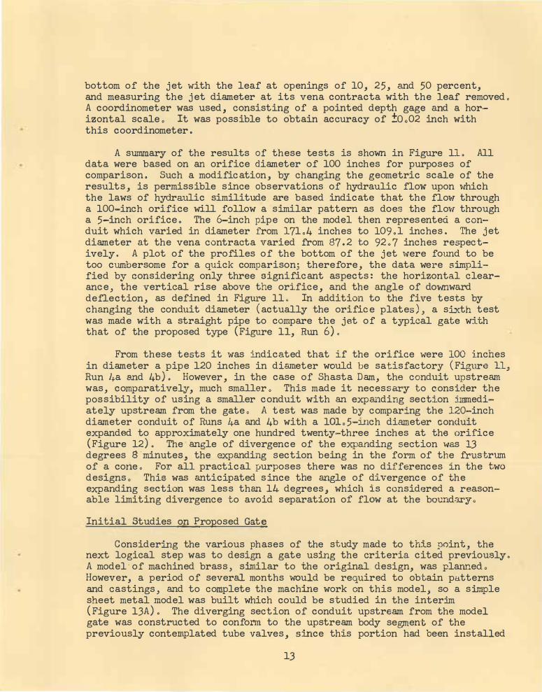
During the course of the tube valve studies, a complete model of an outlet at Shasta Dam on a scale of 1:17 had been built in the Denver laboratory of the Bureau, the scale being established by the ratio of the 6=inch dj.ameter model conduit to the 102-inch prototype conduito To adapt this model,·tc:> the gate tests it was only necessary to alter the conduit length to represent an outlet in the intermediate tier at Shasta Dam and to replace the tube valve with the gate. As shown on Figure 6A, this model included: a cyl:inderical pressure tank, representing a por�, tion of the reservoir; a floating plate in this tank, representing the upstream face of the dam; the bellrnouth entrance to the conduit; the gate; the conduit; and the exit ·section consisting of the deflecting elbow and cone at the face of the spillway. The bead tank, 36 inches in diameter, was equipped with baffles to give satisfactory approach conditions for the flow which was supplied by a 12-inch centrifugal pump direct-�onnected to a variable speed 100-horsepower motor. In the line between the pump and head tank there was a regulating gate and a venturi meter. This arrangement made it possible to obtain any desired head by ad,justments of the motor and regulating valve, and at the same time measure discharge by the venturi meter, which had been calibrated volumetrically in the laboratory.
7

The pressures within the model were recorded from piezometers installed at selected points in the gate and conduit. The piezometer openings, 1/16-inch in diameter or less, were drilled normal to the surface on which they were located. These holes led to copper or plastic tubes soldered or welded to the outside of the model, which were connected by rubber tubing to a manometer or differential gage. Positive pressures were measured by an open manometer, or a mercury differential gage, while negative (subatmospheric) pressures were measured by a water or mercury differential gage. All measurements were made according to accepted laboratory practice. When a positive pressure was recorded the line was bled in such a manner as to fill it with water and eliminate all air bubbles; on the other hand, whenever a negative pressure was recorded all water was blown out of the line. The air demand was obtained by placing sharp-edged orifices at the entrance of the air intake pipes.
Although the problem was concerned with the design of a gate in the intermediate and upper tiers with heads of 223 and 123 feet respectively, all tests were confined to a model of an outlet in the intermediate tier, since those in the upper tier were similar in all respects except shorter in length. Moreover, the tube valve studies had indicated that any control which proved satisfactory in the lower and intermediate tiers would be satisfactory in the upper tier by virtue of the reduced heado
The Original Design
The tests began with a 1:17 model of an 86-inch gate designed somewhat similar to conventional types, hereinafter referred to as the original design (Figure 6). As this gate was short compared with the tube valve, it was necessary to include two sections of conduit to extend its length to that provided for the valve. The upstream section was in.the form of a frustrum of a cone representing a reduction in the prototype conduit diameter f rom 102 to 86 inches. The downstre� section represented a pipe 100 inches in diameter and approximately 163 inches long to join the gate to the 102�inch con-
.duit downstream. This model was made of bronze except for the downstream conduit section and the sides of the frame which were of Plexiglass, a transparent plastic through which it was possible to observe the flow leaving the gate. 'I'he leaf had a projecting sealseat ring on its upstream face, and in the prototype a retractable seal would be located in the upstream frame which would contact the sealseat ring on the leaf; however, this seal was not included in the model since it was too delicate to construct. Air vents were connected to the downstream frame as shown in Figure 6B, the 1/2-inch pipes representing 9-inch prototype vents. Piezometers were located in the frame, leaf, conduit, and air vents, since the tests were to consist mainly of measurin� pressures and air demand for various openings •.
First, the 100 percent or full open position was considered� From the 86-inch orifice a smooth jet flowed clear of the gate slot and into the conduit downstream. A hydraulic jump filled the conduit near the
8

point where the 100-inch pipe joined the 102-inch conduit. The discharge capacity was 4,660 second-feet (prototype) under a 223-foot head, approximately 4 percent less than that of the tube valve; however, this smaller capacity was anticipated because the 86-inch orifice was designed to keep the jump in the conduit downstream from the gate slot, whereas the t,ube valve had been designed to cause the flow to fill the conduit below the valve. Pressures on the leaf, in the slot, and in the 100=inch pipe were slightly negative, creating a small air demand. Only one adverse condition was observedo Negative pressures existed downstream. from Line A (Figure 6D)where the conical upstream pipe joined a short cylindrical section forming the 86-inch orifice. This discontinuity in the flow boundary caused the negative pressures recorded at Piezometers 8 and 11 (Figure 7C). Similar conditions had been encountered before, and the obvious remedyjwas to eliminate the discontinuity by extending the conical section ,s-ownstream to the front edge of the slot. This change was never made since the design had unsatisfactory characteristics at partial openings.
A summary of pressures and air demand at various openings is sho\ffl on Figure 7. To simplify the presentation of the results, all dat� were based on a head of 100 feet, although the tests were made at heads between 35 and 50 feet. No tests were run at the model scale head, 13ol feet, because satisfactory pressure data was difficult to obtain at a head that low. This procedure of testing at any suitable head and transferring the results to a desired head was justified because the pressure at any point in a model of this type is theoretically proportional to the head and actually is so within reasonable limits. Moreover, it follows that the pressure curves on Figure 7 .apply directly to the prototype. It was necessary to adjust the air demand curves to the desired head by use of the relation Qa = C A/2flla, where Qa = the air discharge, C = 0.60 the coefficient of the sharp-edged orifices on t he air pipes, A= the area of the orifices, and Ha = the pressure drop in feet of air deter mined by the Piezometers below the prifices. To determine the prototype air demand a similar procedure would have to be used.
When the gate was partially open the jet appeared to be deflected downwards. As a result, pressures along the bottom of the conduit became positive while those at the top remained negative. The jet also appeared to expand sidewise, filling the gate slot and cutting off the a_ir supply. High-velocity and whirling currents were observ,d in the slot, evidently due to impingement of the jet on the downstream face of the slot. That the air supply was cut off is shown by a comparison of air demand and pressure curves in Figure 7F, In general_, -the pressure controls the air demand, but due to conditions in the slot the maximum air demand was at 70 percent gate opening while minimum pressure in the conduit was at 40 percent gate opening. It was concluded that flow at partial openings would not be satisfactory and that the air vents were improperly located o
Moreover, severe negative pressures were observed on Piezometers 4, 5·, 6, 23, 24, and 28 at partial openings. Piezometer 4 was located on the upstream frame above the seal-ring, while Piezometers 5 and 6 were nearby
9

on the seal-ring itself, where the retractableooal would have been located if. it had been included in the model. Piezometers 23, 24, and 28 were located on t he upstream face of the gate leaf Q A study of pressure curve� for various positions of the leaf (Figures 7B, C, and D) showed that the minimum pressure for any position occurred at point·s in the space between the gate frame and upstream face of the leaf where the portion of:the extended seaJ.-seat ring on the leaf was opposite the seaJ.-ring on the upstream frame. The gap between the leaf and the upstream frame might be considered as a passage through which water flowed. The extended seaJ.-seat ring formed a constriction reducing the area of this passage, thereby inducing low pressures in the same manner as does the throat of a venturi meter. This seal. design was definitely unsuitable /or a gate which would operate at partial. openings.
It was concluded that the original design could be made satisfactory for operation at the wide open position by minor alterations. The conical shape of the upstream pipe would have to be extended to eliminate the break at Line A (Figure 6D) . Also, the seal design would have to be altered to eliminate the possibility of .a vacuum extending the retractable seal while the gate is moving. However, no suggestions were made whereby it would be possible to operate this design at partial openings"
Desirable Characteristics of Remlating Gate
Before commencing further studies it was necessary to decide whether it would be expedient to develop a regulating gate or merely modify the original design for operation at the wide open position only. When the uncertainties of field requirements were considered, there was but one conclusion--the gate should have no restrictions on its operation.
Since gates hithertofore built by the Bureau of Reclamation could not be used for regulation of high-pressure outlets, such as those at Shasta Dam, exploratory work was necessary to ascertain a desirable type. A library search, limited to literature available in the Bureau library, offered no promising suggestions. However, sufficient information was available from experience with existing structures and from experience gained through model tests to formulate fundamental characteristics of a desirable gate. The following were considered important:
1. The leaf should be a simple rectangular box, mounted on wheels or rollers, similar to that of the original design. Such a leaf is small compared with that in the ringfollower-type gates as used at Grand Coulee Dam; however, the large follower sections to fill the slot at the wide open position offered nothing toward the possibility of regulation.
10

2. The leaf should seal at its upstream face. It was found that sealing in this manner would prevent large static pressures in the gate slot and permit the frame to be of lighter construction, especially that portion above the cond�it commonly called the bonnet. The possibility of a large dynamic downpull force on the leaf is also' eliminated. This downpull force would occur with seals at the downstream face of the leaf, for static pressures in the bonnet would act on top of the leaf with a resulting downward force, which could not be balanced when the gate was operating because the pressures on the bottom of the leaf would be reduced by movement of water through the conduit.
3. The upstre.µn face of the leaf should be machined to a smooth plane so the seal on the upstream side of the frame could seat against the leaf at any opening. Undesirable pressures .caused by flow past an extended sealseat ring, as found in the original design, would be completely eli1ninated.
4. An adequate air vent should be provided. The tube valve studies proved conclusively that air was needed when a valve or gate was used for regulation in a closed con= duit. The vent should be large enough to furnish sufficient air so that pressures in the conduit downstream will not drop below -15 feet of water. Also, the air velocity should not exceed some predetermin.ed value :in the interest of quiet operationo The minimum vent size may be determined by care.fully considered model tests, but where feasible it should be as large as practicable, considering structural restrictionso
5. The water should flow past the gate and into the conduit downstream without im.p:L.-iging against the slot in such a. manner as to fill it and prevent the air vent from functioning, nor should the flow strike any surface in such a manner as t o create a region of intense negative pressure. In the test program on the Shasta tube valve successful resu.lts were obtained by using a needle valve developed for free discharge. The smooth jet from the needle valve did not touch the sides of the conduit for some distance downstream, permitting a free flow of air around the jet below the valve. This appeared to be an ideal characteristic for a regulating controlo
As might be anticipated, the main problem resolved itself into a study of flow past the gate. The first three considerations were mechanical problems, which need not be discussed further, although the proposal
11

"that the upstream face of the gate leaf be machined to a smooth plane" was a departure from design practice. Consideration of the air-vent was necessarily postponed until the gate design was more definite.
Development of a Basic Design for a Regµlating Gate
To observe the character of flow past a gate leaf, the original design was operated with the conduit downstream removed . The jet was observed to be rough at partial openings (Figure 8) . As the jet passed under the leaf it appeared to be deflected downwards, and part of it struck the downstream side of the slot to be peeled off into the slot itself . It was apparent that the gate, by its thickness, concealed the basic nature of this flowing jet . To better observe the jet, a simple model was built which consisted of a piece of sheet metal closing over the end of a pipe (Figure 9). This model represented the essential elements of the gate in that the sheet metal plate, representing the upstream face of the leaf, closed over the conduit . The jet, now free of obstructions, took the form shown in Figures 9B and C . In addition to the do�mward deflection shown, the jet spread fan-shaped through an angle of approximately 90 degrees when viewed from above. This jet, characteristic of flow from a gate with a conventional leaf, was not satisfactory since it was desirable that the water flow past the gate without striking the slot.
The cause of this downward, fan-shaped deflection of the jet was the result of a downward component of velocity along the partially closed leaf. To explain it in another way, consider the moon-shaped opening under the gate as an unbalanced orifice having a sharp-edge at its top, along the edge of the leaf, which causes a contraction of the flow; but a suppressed edge at the bottom, along the portion formed by the pipe, with no contraction of the flow (Figure 9A) . The forces causing the contraction on top of the jet are not offset by similar forces underneath, and the resultant flow is downwards. It appeared that if a force could be applied underneath the jet to cause a contraction, which would offset or balance the contraction above, the flo.w would be improved . This was accomplished by placing a sharp-edged orifice or nozzle in the pipe upstream, adjacent to the leaf ( Figure 10) . A solid, comparatively level jet formed which did not spread sidewise. Fins occurred at the point where the leaf contacted the orifice , but they were thin, representing an insignificant quantity of water .
This use of an orifice or nozzle at the end of the pipe was considered worthy of further investigation. It was desirable to know how the jet would be affected by different ratios of conduit diameter to orifice diameter and by the shape of the orifice lip . Tests were made using five different orifice sizes with a 6-inch pipe. · Two types of orifices were used, one having a narrow 15-degree lip, and the other a 45-degree lip . A third type, having a flatter lip of 60 degrees, was considered but the jet, similar to that from a straight pipe, was not desirable . The test with each orifice consisted of measuring the profile along the
12
bottom of the jet with the leaf at openings of 10, 25, and 50 percent, and measuring the jet diameter at its vena contracta with the leaf removed . A coordinometer was used, consisting of a pointed depth gage and a hor·izontal scale o It was possible to obtain accuracy of !O o02 inch with this coordinometer.
A summary of the results of these tests is shown in Figure lL All data were based on an orifice diameter of 100 inches for purposes of comparison . Such a modification, by changing the geometric scale of the results , is permissible since observations of hydraulic flow upon which the laws· of hydraulic similitude are based indicate that the flow through a 100-inch orifice will follow a similar pattern as does the flow through a 5-inch orifice. The 6-inch pipe on the model then represented a conduit which varied in diameter from 171 . 4 inches to 109.1 inches. The jet diameter at the vena contracta varied from 87 . 2 to 92 . 7 inches respectively . A plot of the profiles of the bottom of the jet were found to be too cumbersome for a quick comparison; therefore, the data were simplified by considering only three significant aspects : the horizontal clearance, the vertical rise above the orifice, and the angle of do.-mward deflection, as defined in Figure 11 . In addition to the five tests by changing the conduit diameter ( actually the orifice plates ) , a sj_xth test was made with a straight pipe to compare the jet of a typical gate w:i.th that of the proposed type (Figure 11, Run 6) .
From these tests it was indicated that if the orifice were 100 inches in diameter a pipe 120 inches in diameter would be satisfactory (Figure ll, Run /+a and 4b} . However, in the case of Shasta Dam, the conduit upstream was, comparatively, much smaller o This made it necessary to consider the possibility of using a smaller conduit with an expanding section immediately upstream from the gate o A test was made by comparing the 120-inch diameter conduit of Runs 4a and 4b with a 10L5-inch diameter conduit expanded to approximately one hundred twenty-three inches at the orifice (Figure 12) . The angle of divergence of the expanding section was 13 degrees s · minutes, the expanding section being in the form of the frus t.rum. of a corie o For all practical purposes there was no differences in the two designs o This was anticipated since the angle of divergence of the expanding section was less than 14 degrees , which is considered a reasonable limiting divergence to avoid separation of flow at the boundary o
Initial Studies 9lll'.roposed Gat�
Considering the various phases of the study made to this point, the next logical step was to design a gate using the criteria cited previously o
A model · of machined brass , similar to the original. design, was planned o
However, a period of several months would be required to obtain patterns and castings , and to complete the machine work on this model, so a simple sheet metal model was built which could be studied in the interim (Figure 13A) . The diverging section of conduit upstream from the model gate was constructed to conform to the upstream body segment of the previously contemplated tube valves , sj_�ce this portion had been installed
13

in all of the outlets in Shasta Dam (Figure 3 ) . Thus, the passage expanded beLl-shaped from a 6-inch diameter conduit to 7o84 inches, representing 102 and 133 inches on the prototype. An orifice with a 45-degree lip reduced the· diameter f rom 7 084 inches to 5 o 53 inches . The 5 . 53-inch orifice, representing 94 inches prototype, was selected to give a jet diameter of approximately 86 inches (prototype), which was comparable with that of the original design . Since the jet would deflect downwards at partial openings, it appeared advantageous to place the center of the orifice 0 .118 inches (2 inches prototype) above the center of the conduit .
To observe the flow, the sides of the gate frame and the conduit section downstream were constructed of Plexiglass . This conduit was in the form of an inverted U, or horseshoe, at the gate, with a short transition to the circular pj.pe o The purpose of the horseshoe-shaped opening was to prevent the jet from striking inside the gate slot during operation at partial openings . An air duct was placed above the transition to represent a connection to the existing prototype vents, located a short distance downstream. The opening from the duct into the top of the conduit extended downstream 5 088 inches· (model) from the gate or about one pipe diameter o
The first test was made to observe the jet with the conduit removed (Figure 14) . With the gate wide open, wisps of water appeared to leave the body of the jet, evidently due to turbulence in the conduit upstream. This was not considered as unfavorable, for a similar condition exists when water is discharging from the end of a straight pipe o As the gate closed the jet became smoother, except for fins forming at the side where the leaf contacted the orifice . At an opening of 50 percent, these fins stuck inside the slot; however, no great quantity of water was involved for they were less than 1/16-inch thick . As the gate closed further, the fins did not touch the slot but fell below the jet as shown on Figures 14C and D .
A preliminary test with the conduit in place indicated that the opening from the air-vent in-to the top of the conduit could not be placed one pipe diameter downstream. When the gate was raised to its open position a hydraulic jump filled the conduit below and moved upstream past the air-vent opening, filling it with water . Wat,er rising to any height in the vent could not be tolerated because in the prototype a header, approximately forty feet above the conduit , joined all of the vents in the tier and it was feared that water reaching the header would interfere with proper aeration of the units. The opening of the air-vent in t he top of the model conduit was moved upstream within 1 inch of the gate (model) since the jump filling the pipe did not move that far upstream.
Piezometers were located in the model as shown in Figura lJA . Curves showing the relationship of pressure, air demand, and discharge to gate opening, based on a l00w,foot head, are on Figure 13D . In general, pressures inside the conduit were slightly negative
14

(subatmospheric), not exceeding 2 feet of water (Piezometers 1, 2, 3 , 4, and 5). Where the jet struck the conduit, pressures were positive (Piezometers 6 through 12) . The more severe negative pressures at Piezometers 13 and 14 were anticipated because they were located downstream from a step-like increase in pipe size. The step was formed where the proposed conduit section below the gate was 100 inches in diameter (prototype) and the main conduit was 102 inches, making an offset of 1 inch in the flow boundary. This . change of pipe size was undesirable but considered necessary for structural reasons .
The change of direction of the boundary at the end of the transition was of such a nature that negative pressures were anticipated at Piezometers S and 9 located dorm.stream from the transition. The presence of positive pressures recorded by the Piezometers could not be explained . Perhaps the pressure resulted from impact as the jet
. from the orifice contacted the pipe, or from the fact that there was no sharp break at the end of the model transition. No serious consideration was given to this condition for subsequent tests would involve changes of the design which would influence these pressures .
The general appearance of the flow in the · conduit was satisfactory except for two conditions . First, two waves, or layers of wat�r began at each side of the transition and circled over the top of the conduit. Secondly, at �he wide open position a part of the jet splashed into the air-vent. Apparently the latter condition was a result of placing the orifice centerline above the conduit centerline.
A second test was made by eliminating the transition and using only a circular section downstream from the gate and lowering the orifice to the conduit centerline (Figure lJB ) . The appearance of flow in the conduit downstream from the gate was improved, while pressures were not materially changed (Figure 13E) . However, at openings less than 50 percent the appearance of the jet in the gate slot was not as desirable as before . As the gate closed, deflecting the jet do'Wnwards, a point was reached where the jet began to strike the downstream face of the gate slot along the lower edge of the circular opening into the conduit, peeling off water into the slot to form a roller below the leaf. No large quantity of water was involved, and the severe turbulence observed in the original design did not exist . Nevertheless, it was recognized that, should the final design use a circular conduit, this condition should be investigated carefully.
A third test involved a design using a long transition as a means of improving the appearance of the jet both in the gate slot and in the conduit downstream (Figure lJC) . The flow with this transition was similar to that observed in the first test, except the waves which tended to circle the top of the transition were not pronounced and the tendency for water to be splashed in the air-vent was greatly reduced . As far as appearance was concerned, it was the most acceptable design. Again, pressures were, in general, slightly negative or positive, with
15
/

the exception of severe negative pressure at Piezometer g located downstream from the 5 .gg_ to 6-inch step in conduit size (Figure 13F). It was recommended that this abrupt change in conduit diameter be eliminated to prevent the unfavorable pressures downstream. Moreover, with this break in the boundary it was not possible to evaluate the effect on the long transition on the pressures in the conduit immediately downstream .
The model of machined brass, which was under construction while the tests described above were in progress, included a transition similar to that in Test 3. In this new model , the downstream section of conduit, including the transition, and the sides of the gate were of Plexiglass. Photographs of the gate are shown in Figures 15 and 16 . As may be seen in Figure 15B, a solid jet flows past the gate slot with no part striking the slot except the small fin originating at the point where the leaf contacts the seat. The entire slot, including the space surrounding the jet and under the leaf, and the conduit downstream were aerated by a single vent. This design was proposed for the outlets in Shasta Dam.
High Head.0
Tests
The pressure curves shown on Figure 13 were based on a 100-foot head, although the actual test heads did not exceed 60 feet . It was desirable to study the model under a greater head to verify the relationship that pressure was proportional to head since this study was not only concerned with the flow of water, but also with the flow of air into the vent at the gate and to the conduit downstream to relieve negative pressure. As stated previously, the phenomena associated with the air requirements of an outlet are not sufficiently known at present to predict precisely the prototype behavior . The factors of uncertainty include : the effect of expansion of air under subatmospheric pressure; the effect of insufflation of air into the water as velocities increase; and the exact nature of the mechanical action causing the air demand , which is partly by a shear action along the surface of the jet, partly by insufflation into the water, and partly by a pumping action where the jet fills the conduit, generally near the elbow at the outlet exit . It was believed , however, that if high head tests verified the results obtained in the laboratory, the relationship that pressure was proper= tional to head could be considered as reliable.
One of the needle-valve outlets at Boulder Dam had been extended by a 20-inch line for high head tests on a 1:5.1 model of the tube valve originally planned for all of the outlets at Shasta Dam. With an adapter flange to this 20-inch line, it was possible to study the 6-inch model of the proposed gate under heads up to 350 feet of water (Figure l?A). The model was altered to withstand the high pressure by replacing the Plexiglass transition with one of brass. At this time several minor revisions were made in the design and the model was testEd. before taking it to Boulder Dam. The length of the transition was
16

shortened and the pipe size at the end of the section was increased from 5 . 88 to 6 . 00 inches to eliminate the change in diameter where it joined the conduit ·aownstream . Twenty-seven piez-ometers were installed in the gate, transition, and conduit downstream to obtain pressures in this model (Figure l?B) .
The preliminary test in th.e Denver laboratory ·revealed negative pressures downstream from. the transition . This was not the case in the former test on the model shown on Figure 13A, where pressures downstream from the similar short transition were positive . Logically, the pressures downstream from the transition should be negative, and it was concluded that the former design, Figure 13A, was a special case, and that a transition such as that in the high head model might not be satisfactory. Therefore, a circular conduit downstream from the gate, similar to Figure lJB but 6 inches in diameter, was also considered as a probable final design and this alternate model was prepared for tests at Boulder Dam (Figure 17C ).
The tests at Boulder Dam consisted of pressure and . air demand measurements (Figures 17D and 17E) . The head varied from 320 feet, when the gate was wide open, to 349 feet when closed. This head was determined from the pressure at Piezometer A (Figure 17A). However, a correction was required to account for an excess length of pipe in the model, the correction being the difference in pressure between Piezometers B and 1 . The velocity heads in the 20-inch pipe at Piezometer A were not included in these computations since they were found to be negligible . The high pressures at Piezometers A, B, 1, and 2 were measured on a fluid pressure scale . Other pressures were measured by a mercury differential gage.
With the transition section (Figure l?B) pressures in the conduit above the jet were not more than 11 feet below atmospheric , but at the same time pressures 25 feet below atmospheric were observed at Piezometers 22, 23, 25, 26, and 27, all downstream from the transition • . In reading the pressures , it was noted that the mercury in the manometer would often drop to a certain value, pause , and then drop further. From past experience on similar models it was known that this was an indication that an air pocket formed at the piezometer opening when the tube was connected to the manometer, to persist for a few seconds, then disappear .
With the circular section instead of the transition, no pressure more than 9 feet below atmospheric was observed except at Piezometer 15 (Figure 17E) . This was unexpected, for Piezometer 15 was too far_ downstream to be critical. A later inspection revealed a burr at the edge of the opening to be the cause .
In observing the model at Boulder Dam, it was noted that a spray filled the gate slot, obscuring it from view . This was attributed ·to
17

the high head causing a leak between the frame and leaf at the seal . This does not infer that a prototype seal would leak, for the model seal was simplified .
When measuring air demand, the pressures recorded by the manometers were not steady, suggesting a fluctuation in air quantity. This condition was more noticable with the circular section than with the transition. It might be a source of vibration in the prototype, but in the model there was no undue vibration . The entire model vibrated under the high head at a fr��uency which could not be determined, probably at 15 or 20 cycles per second, slightly less than a sonic frequency. The air-vent tended to whistle, causing considerable noise during testing. In the light of available information, it is imP,ossible to predict the intensity of vibration which will occur in the prototype or the noise which will be produced in the vents. It is only possible to state that there will probably be a roar from the movement of air .
Comparison of Pressure.s at High and Low Heads
Upon returning to the Denver laboratory the pressure measurements were repeated to obtain comparative data at lower heads, about 50 feet of water . The tests at high and low heads were compared bf referring all pressures to a common head of 100 feet (Tables 1 and 2) . Table 1 concerns the pressures with the transition section downstream from the gate ( Figure l?B) while Table 2 is for the model with a circular section downstream (Figure 17C). In general, the comparison in this manner was sufficient to show that the pressure may be assumed to be proportional to the head, since the differences in most readings could be attributed to errors of observation . Large differences at some piezometers occurred because the pressures fluctuated, mald.ng accurate readings difficult . However, there was a tendency for the negative pressures to be more severe under the high heads o There were several reasons why this should be soo The jet trajectory at high heads was flatter at any point, reducing the boundary pressure under some circumstances . Also, the turbulence of flow was more intense. More important, however, there existed an unavoidable error in the measuring technique. In blowing water from the piezometer lines, preparatory to recording the negative pressure, there was a tendency for a bubble to persist at the piezometer opening, causing separation of flow at the boundary thereby relieving the negative pressure to some extent . Such bubbles tend to persist at low heads, while at high heads the turbulence of flow is usually sufficient to remove them . As aforementioned, this condition was observed in the tests at Boulder Dam .
A study was made to show that the unfavorable negative pressures recorded by Piezometer 15 in the second high-head test using the circular conduit did not indicate a true condition (Figures l?C and l?E) . Examination of the piezometer opening revealed a burr at its upstream edge which tended to confirm that the pressures recorded were too low .
18
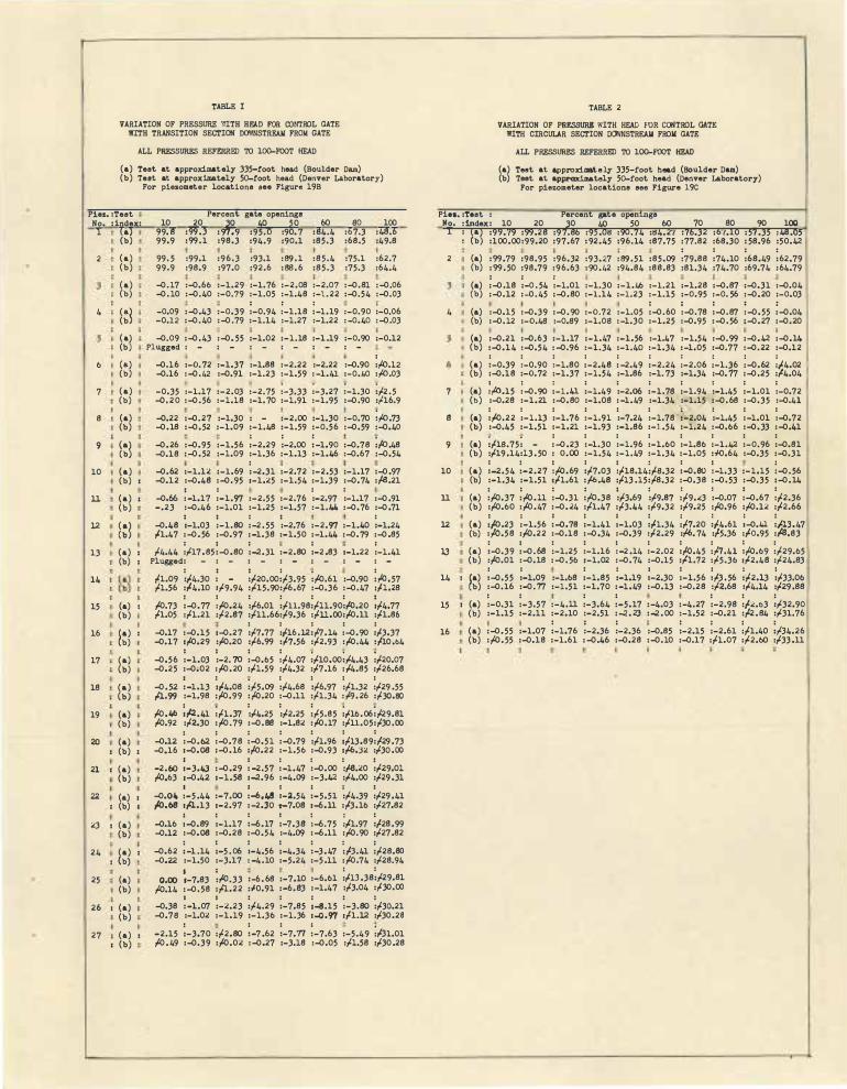
TABLE I
VARIATION OF PRESSURE ?/ITH HFJ.D FOR OONTROL GATE llITH TRANSITION SECTION DOWNSTREAII FROII GATE
ALL PRESSURE.S REFERRID TO 100-FOOT HEAD
(a) Test. at approximately 335-foot head (Boulder Dam) (b) Test. at approximately 50-foot head (Denver Laboratory)
For piezometer locations aee Figure 19B
Piez. :Test No. :index: l (a)
2
4
6
7
8
9
10
ll
12
13
14
15
16
17
18
19
20
(b)
(a) (b)
(a) (b)
(a) (b)
(al (b
(a) (b)
(a) (b)
(a) (b)
):l (a) (b) I
(a) ' (b)
[:l (a) I (b) I
(a) I (b)
(a) I (b)
i:l i:l (a) (b)
(a) I (b) 1
21 , (a) (b)
22 (a) , I (b) 1
.!J I (a) (b)
24 (a) I ' (b)
25 (a) (b)
26 I (a) (b)
27 (a) I ' (b)
Percent 10 20
� 99.8 :99.3 : 9�9 99.9 :99.1 :98.J
gate openings 40 50
:95.0 :90. 7 :94.9 :90.1
60 80 100 :84.4 :67.J :48.6 :85.J :68.5 :49,8
99, 5 :99.1 :96,J :93.1 :89.1 :85,4 :75,1 :62,7 99-9 :98.9 :97.0 :92.6 :88.6 :85,3 :75,J :64.4
-0.17 :-0.66 :-1.29 :-1. 76 :-2.08 :-2,07 :-0,81 :-0,06 -0,10 :-0.40 :-0.79 :-1.05 :-1.48 :-l.22 :-0.54 :-0.0J
. . . . . . -0.09 :-0.43 :-0.39 :-0.94 :-1.18 :-1.19 :-0.90 :-0,06 -0,12 :-0.40 :-0. 79 :-1.14 :-1.27 :-1.22 :-0,IIJ :-0.0J
-0.09 :-0,43 :-0. 55 :-1,02 :-1.18 :-1 .19 :-0,90 :-0,12 Plugged : - : - : - : - : - : -
: -0,16 :-0. 72 :-1.37 :-1.88 :-2.22 :-2.22 :-0.90 :,4).12 -0,16 :-0,42 :-0.91 :-1.23 :-1.59 : -1.41 :-0./IJ :,4),03
-0.35 :-1.17 :-2.0J :-2. 75 ;_3_33 ;_3.27 ;_1,30 ;,'2,5 -0.20 :-0,56 :-1.18 :-1. 70 :-1,91 :-1.95 :-0,90 :,'16,9
-0.22 :-0.27 :-1,JO : - :-2,00 :-1.30 :-0.70 ;,4).73 -0.18 :-0.52 :-1.09 :-1.48 :-1,59 :-0,56 :-0.59 :-0.40
-0.26 :-0.95 :-1.56 :-2.29 :-2.00 :-1.90 :-0.78 ;,io.48 -0.18 :-0.52 :-1.09 :-l.J6 :-1.13 :-1.46 :-0.67 :-0,54
: -0.62 :-1.12 :-l.69 :-2,31 :-2,72 :-2.53 :-1,17 :-0.97 -0,12 :-0,48 :-0,95 ,-1,25 :-1,54 :-1.39 :-0. 74 :,te.21
t : : : -0,66 :-1.17 :-1,97 :-2,55 :-2,76 :-2,97 :-1.17 :-0,91 -.23 :-0,46 :-1.01 :-1.25 :-1,57 :-1,44 :-0.76 :-0.71
t t : t : -0,48 ,-1.0J :-1.80 :-2 ,55 :-2.76 :-2.97 :-1./IJ ,-1.24 1-1.47 :-0,56 :-0.97 :-1,38 :-1.50 :-1,44 :-0,79 :-0,85
: t : ' : ,'4.44 :l-17,85:-0,80 :-2,Jl :-2.80 ,-2,83 ,-1.22 :-l.41
Plugged: - : - : - : - : - : - : -: t t : • :
f,l,09 :,'4,JO : - :,'20,00:,'J,95 :,'o,61 :-0.90 :f{),57 ,'l.56 :l-4,10 1,'9,94 :l-15.90:,'6,67 :-0,36 :-0,47 ,,tl,28
t I : : : : t ,'o.73 ,-0.77 :,'o.24 :,'6,01 :,'ll,98:,'ll.90:f{J,20 ,,'4,77 ,'1,05 :,'l.21 :,'2.87 :,'ll.66:,'9,36 :,'ll.OO:,'o,11 :,'1.86
: : : : : -0,17 :-0.15 ,-0.27 :,'7,77 :,'16.12:,'7.14 :-0,90 ,,tJ.37 -0,17 ,,'o.29 :,'o.20 :,'6.99 ::/-7,56 :,'2.93 :,'o,44 :,l,10,64
t I : : , , • -0,56 :-1.0J :-2. 70 :-0.65 :,'4,07 :,'10,00:l-4-43 :,'20.07 -0,25 :-0;02 :,'o.20 :,l,l,59 :,'4,32 :,'7 ,16 :,l,4.85 :,'26.68
I : • : : : : -0,52 ,-1.13 ,,t4.08 :,'5,09 :,'4.68 ,,'6.97 :,'1.32 :,'29 ,55 /:J.,99 :-1,98 :,'o,99 :f{),20 :-0.ll :,'l.34 :,l,9,26 :,'J0,80
: . : : : . . ,'o,46 ,,'a.41 :,'l,'57 :,l,4,25 :,'2,25 :,'5,85 :,116,06:,'29.Bl ,'o.92 :,'a.JO :,'o. 79 :-0,88 :-l,82 :,'o.17 :,'ll.05:,'JO,OO
: : : : : : : -0,12 :-0.62 :-0,78 :-0,51 :-0,79 :,'l,96 ,,'lJ,89:/29,73 -0.16 ,-o.08 ,-0.16 ,,to.22 :-1.56 :-0.93 ,,'6.J, :,'JO,oo
' l : : : : -2,60 ,-J.43 :-0.29 : -2,57 :-l.47 :-0.00 ,,is.20 :,'29,0l /-0,63 :-0,42 ,-l,58 ,-2.96 :-4.09 :-J.42 :l-4,00 :,'29.Jl
a , : : : : -0.01, :-5 ,44 :-7.00 :-6,48 1-2.54 :-5-51 :l-4-39 :,'29,41 /-0.t,8 ,,tl..13 ,-2.97 : -2.JO .-.7.08 ,-6.11 :l-3.16 :,'27.82
-o.16 :-o.89 :-1.17 :-6.11 ;_7,30 :-6.75 :1-1.97 :12a.99 -0.12 :-0.08 :-0,28 :-0,54 :-4,09 :-6,11 :/-0.90 :,'27 .82
-0.62 :-1 .14 :-5 .06 :-4,56 :-4,34 ;_J.47 ;1-3,41 :,'28.BO -0.22 :-1.50 :-J.17 : -4,10 :-5.24 :-5 ,ll :,'o,74 :,'28.94
I : : : 0,00 1-7,83 :,4).JJ i-6 .68 :-7,10 :-6.61 :/-13 .JB:,'29,Bl
/-0.14 :-0,58 :,'l.,22 :I0,91 :-6.83 :-1.47 :,'J,04 :/-J0,00 I I : : : : :
-0,JB :-1,07 :-2.23 :,'4,29 :-7,85 1-8.15 :-J,80 :,'JQ.21 -0,78 :-1.02 :-1.19 :-1,36 :-1.36 ,-0,97 ,1-1.12 :I-J0.28
-2.15 :-J. 70 :,'2.80 :-7 .62 :-7. 77 :-7 ,63 :-5 ,49 ;1-31.01 ,'o,49 :-0.39 :,'o,02 :-0,27 :-J.18 :-0.05 :,'l.58 :,'J0,28
TABLE 2
VARIATION OF PRESSURE WITH HEAD FUR CONTROL GATE WITH cmcULAR SECTION D(l'INSTREAII FROII GATE
ALL PRESSURE.S REFERRID TO 100-FOOT HEAD
(a) Toot at approxi ... tely 335-foot hoed (Boulder Dam) (b) Toot at appraxl..5tol7 50-foot hoad (Denver Laborator7)
For piezom.eter locations see Figure l9C
Pies. :Teat : Percent gate openings No. : index: 10 20 30 11J 50 60 70 80 90 100 1 : \&) :9y."(y :YY.28 :Y"/,86 :Y) .08 :W,"/4 :84.2'/ no.J� :o·,.10 :57.3) ,,..,.U)
: (b) :100.00:99.20 :97.67 : 92.45 :96.14 :87.75 :77.82 :68.JO : 58.96 :50,42
2
4
7
8
9
10
11
12
13
. . . . . . . . (a) :99.79 :98.95 :96.J2 :93,27 :89,51 :85.09 :79.88 :74.10 :68,49 :62.79 (b) :99,50 :98.79 :96,63 :90.42 :94,84 :BB.BJ :81,34 :74.70 :69.74 :64.79
. . . . . . (a) :-0,18 :-0 , 54 :-1.01 :-1.30 :-1.46 :-l.21 :-1.28 :-0,87 :-0.Jl :-0,04 (b) :-0,12 :-0.45 :-0,80 :-l.14 :-l.23 :-1.15 :-0,95 :-0, 56 :-0,20 :-0,0J
. . . . . . . . . . (a) :-0.15 :-0,39 :-0.90 :-0,72 :-1.05 :-0.60 :-0,78 :-0,87 :-0.55 :-0,04 (b) :-0,12 :-0.48 :-0.89 :-1.08 :-1.30 :-1.25 :-0.95 :-0,56 :-0,27 :-0.20
(a) :-0,21 :-0.63 :-1.17 :-1.47 :-1,56 :-1,47 :-1.54 :-0.99 :-0,42 :-0.14 (b) :-0.14 :-0.54 :-0,96 :-1.34 :-l.40 :-1.34 :-1,05 :-0.77 :-0.22 :-0,12
(al
:-0.39 :-0.90 :-1.80 :-2.48 :-2,49 :-2.24 :-2.06 :-1.3,6 :-o.62 :,'4.02 (b :-0,18 :-0, 72 :-1.37 :-1.54 :-1.86 :-1. 73 :-1.34 :-0. 77 :-0,25 :,'4.04
1 : : : : : : : : : (a) :,'0,15 :-0,90 :-l.41 :-1.49 :-2.06 :-1,78 :-1,94 :-1,45 :-1.01 :-0.72 (b) :-0.28 :-1.21 :-0,80 :-1.08 : -1.49 :-1,34 :-1.15 :-0.68 :-0,35 :-0,41
: : : : : : . : : : (a) :,'o,22 :-1.13 :-1,76 :-1,91 :-7.24 :-1,78. ,-2.04 :-1,45 :-l.01 :-0,72 (b) :-0.45 :-1.51 :-1,21 :-1.93 :-1.86 :-J..54 :-1.24 :-0.66 :-0.JJ :-0,41
: : : : : : : : (a) ;,t1s.75; - :-0.23 :-1.JO :-1.96 :-1.60 :-1.86 :-1,42 :-0.96 :-0.81 (b) :,'19,14:lJ.50 : o.oo :-1.54 :-1,49 :-1.34 :-1,05 :f-0,64 :-0.35 :-0,Jl
(a) :-2,54 :-2.27 :/-0,69 :,'7,0J :,'18.14:,'8.32 :-o.80 :-1,33 :-1,15 :-0.56 (b) :-1,34 :-1.51 ,1-1.61 :/-6.48 :,'1J .15:,'8.J2 :-0,38 :-0,53 :-0,35 ,-0.14
: : : : s : : : ' : (a) :/-0,37 :f{J,ll :-0,Jl :,'o.JB :I-J,69 :/-9,87 :,'9.�J :-0,07 :-0.67 :,'2,36 (b) :/-0.60 :,'o.47 :-0.24 :,'1.47 :,'J,44 :l-9,32 ,,'9.25 :f{),96 ,/-0.1" :,l,2.66
(a) ;/-0,23 :-1.56 :-o,7s :-1.41 :-1.03 :1-1.34 :1-1.20 :l-4,61 :-0,41 :M,47 (b) :/-0,58 :/-0.22 :-0,18 :-0,34 :-0,39 :,'2.29 :,'6, 74 :/-5.36 :/-0,95 :,ts.BJ
(a) :-0.39 :-o.68 :-1,25 :-1.16 :-2 .14 :-2.02 :f{),45 :h,41 :/-0.69 :,'29,65 (b) :,to.01 :-0.18 :-0.56 1-1.02 :-0.74 :-0,15 ,1-1.12 :l-5,36 ,1-2.48 :,'24.83
14 I (a) :-0.55 :-1.09 :-1.68 :-1,85 :-1,19 :-2.JO :-1,56 :/-J ,56 :,'2.lJ :I-JJ,06 (b) :-0.16 :-0.77 :-l.51 :-1.70 :-l.49 :-0.13 :-0.28 :,'a.68 •l-4,14 :,'29,88
15
16
: : : ' : : : , (a) :-0,31 :-3,57 :-4,11 :-3,64 :-5,17 :-4.0J :-4,27 :-2.98 :,':1,oJ •l-32,90
(b) :-1.15 :-2.ll :-2.10 :-2,51 :-2.23 :-2.00 :-1,52 :-0.21 :,l,2.84 :l-31.76
(a) :-0,55 :-1.07 :-1,76 :-2,36 :-2,36 :-0,85 :-2.15 :-2.61 :,'1./IJ :1-34,26 (b) :/-0.55 :-0,18 :-1.61 :-0.46 :-0,28 :-0,10 :-0,17 :,'l,07 :l-2,60 :,'JJ.11

By placing the pipe containing Piezometer · l5 in a continuous conduit and �•scertaining the normal pressure gradient, an error of 2 o 5 percent of the velocity head was found. This error disappeared when the burr was removed. Assuming a velocity head of 320 feet past Piezometer 15 , the error would be -8 feet , which would make the pressures on Piezometer 15 compare favorably with other pressures in the conduit .
Development of the Final Design
A gate with a -circular conduit downstream, similar to Figure 17C, was recommended as the final design for Shasta Dam. However, further tests were necessary to study certain details before a final design could be claimed o These studies included : (1) A final test to verify that a transition should not be used downstream from the gate; (2) Modifications of the design to increase the discharge capacity; (3) Observations to study the effect of the Jet striking the downstream side of the gate slot; (4) Observations to consider the effect of the fin originating at points where the leaf contacts the circular orifice; and (5) A survey of pressures in the proposed final design.
An opening at the downstream side of the gate slot in the form of ,,_ · an inverted U, or horseshoe, was desirable. When the gate closed, deflecting the jet downward, the jet would continue to flow dir,ectly into the conduit; whereas, with a circular opening, the bottom of the jet would strike the edge of the slot and some flow would peel off into the slot . However , with the horseshoe-shaped opening, a transition section was required to join it to the circular conduit downstream. Negative pressures below the model transition shown in Figure 17B made that design unsatisfactory. An air-vent between Piezometers 22 and 23 was suggested as a remedy, but it did not offer complete relief . Moreover, it was under pressure at the full open position . Undoubtedly, a satisfactory venting system could be designed, but a solution of this type would not be acceptable for the outlets in Shasta Dam because of structural difficulties o
A short transition, similar to that shown on Figure 13A, was tried, but i n contrast with the results of a former test (Figure 15D) negative pressures were found below the transitiono There were two important differences in the models. First , the orifice was above the centerline of the conduit in the former test , tending to make the jet contact the pipe further downstream; and secondly, in that test the change from the transition to the circular section was on a curve, whereas in the new design the change was a sharp break .
Although an acceptable transition could be designed through model tests, in the light of satisfactory pressure conditions with the more simple circular section (Figure l?C) further studies using a transition -were not justified. The disadvantage of a circular opening at the downstream side of the gate slot was not as critical as it seemed at first because the quantity of water striking the edge of the slot and
19

peeling off was not large . It was not until the capacity of the outlet was increased by enlarging the orifice that this flow into the slot was seriously considered .
When the gate was recommended for use at Shasta Dam, the discharge capacity was questioned. Measurements on the model indicated a discharge of 4, 540 second-feet under a head of 223 feet , compared with a discharge of 4,890 second-feet for the tube valve fonnerly proposed o This reduction of capacity was not acceptable and it was necessary to enlarge the orifice from 94 to 96 inches (prototype). The larger orifice increased the disch�ge to 4, 750 second-feet o A suggestion that the 96-inch orifice be increased further was not acted upon because the conduit filled completely when the gate was opened fully. Under this condition there was a hydraulic jump next to the gate and 1/2-inch air-vents (model) in the sides of the gate slot were required to keep the jump out of the slot itself . In fact with runs at heads higher than the scale head the jump filled the slot.
This enlargement of the orifice from 94 to 96 inches required that the floor of the slot be r ecessed next to the orifice to permit installing a larger seal in the prototype . A test with the floor of the model lowered 3/8 inch revealed that a recess on the floor next to the orifice woµJ.d not affect the flow and that a washing acticn in the recess by sJ�k water would prevent detritus from lodging :in it.
With this larger orifice the peeling off of the jet on the downstream side of the slot became pronounced, and high-velocity whirlpools formed, filling the portion of the slot under the leaf with an air-water mixture. Piezometric measurements revealed only slight negative pressure at the core of these whirlpools where they touched the sides of the frame. In terrninology of fluid mechanics, these whirls were r r forced vortices " with neb.ural pressure at the core and positive pressure outside . The negative pressures prevalent in the better known "free vortex" were absent. Therefore, it was believed that these whirlpools would not cause . material damage. The effect of these whirls could not be ascertained in the small model, so the following recommendations were made as a matter of caution:
1 . The dom1st.ream side of the gate slot, below the centerline of the pipe, be faced with wear plates which can be easily replaced . If such plates are not necessary they may be dispensed with in later designs.
2 . These plates be flush with the tracks, and all connecting bolts be countersunk and the holes filled .flush to the surface with lead , "Smooth on, " or a similar material . A projecting bolt or surface may induce local cavitation, which cannot be detected in the small model.
20

3. The corner where the 102-inch pipe connects to the wear plates in the slot be ground to a smooth edge.
4 . All unnecessary projections on the sides and bottom of the slot be eliminated o
It was found possible to �void much of the peeling off action of the jet by extending the bottom of the circular pipe upstream into the gate slot to catch the jet when it was deflected downwards , and to guide it into the conduit. It was proposed that a portion of the pipe bounded by a 60--degree arc (30 degrees each side of the vertical centerline) be extended into the slot. Although tests indicated that a design of this type would function in a satisfactory manner, it was not desirable as a special bottom shape on the gate leaf would be required .
C onsideration was given to the effect of the two fins originating at the points of contact of the gate with the circular orifice·. In the prototype, these fins or jets should be about one inch thick. i'}le effect of a jet of this size striking the sides of the gate slot under a 223-foot head was a matt.er of conjecture o As far as known, if water is free of silt no erosion should occur . From the theoretical pressure distribution of a jet striking a plate, it also follows that cavitation should not occur . However, if it be desirable to prevent fins from striking in the gate slot, a deflector might be used. In the model, the fins were deflected to a large extent by placing two vertical plates parallel to the direction of flow on the gate-leaf bottom. These plates were approximately 100 inches ( prototype) apart. The test indicated that the vertical height of the plates should be at least 8 inches to be effective o This would require a special chamber in the floor of the slot, thus a deflector was not considered as a solution at Shasta Dam.
The final design of the model (Figure 18) was that tested previously at Boulder Dam (Figure 15C ) except the orifice diameter had been increased from 5o53 to 5o65 inches representing a change in the prototype from 94 to 96 inches . Also, two 1/2-inch air vents representing 8-inch pipes were installed in the Plexiglass sides of the frame o Twenty-seven piezometers were installed to measure pressures o
A series of measurements of pressure, air demand, and discharge capacity was made at each 10-percent openingo A head of approximately 50 feet was used. Also, at 100-percent opening a head approximating the scale head of 13 ol feet was used to c onsider properly the effect of the siphon action in the elbow do�mstream, for the conduit below the gate was full at that opening. Regardless of the heads used in the tests , all data were referred to a head of 100 feet for convenience in making comparison at other heads ( Figure 18C ) .
The pressure at Piezometer 6 (Figure 18B ) was considered as the base pressure in the outlet at openings of 80 percent or less , because
I
21

this Piezometer was located in the conduit above the jet . The base pressures for various openings are enumerated on the graph of Figure 18C . From the indications of the high-head tests , the minimum pressure, - 1.34 feet per 100 feet of head, will probably be lower in a prototype structure, perhaps as much as -2 . 50 feet per 100 feet of head. As far as can be ascertained by the model, this base pressure should be virtually the minimwn in the outlet, except for the unfavorable conditions found in the outlet elbow at the exit . A subatmospheric pressure of 25 feet of water was measured on the bottom of this elbow; however, the outlet conduit and elbow were built at the t ime the tests to design the gate were in progress, and since pressure conditions in the elbow were independent of the gate design, they did not become part of this problem.
Appl:i£ation of Gate as a }'ree Discharge Valve
During tests to improve the shape of the jet (Figures 9 and 10) , it was suggested that the gate be considered as a freedischarge valve in future installations where it would be attached at the exit end of a conduit. Although the jet was rough compared with the circular synnnetrical jet of the more common needle valve, it nevertheless discharged water in a given direction, which is the essential requirement for a free discharge valve. Figure 14 shows the flow characteristics when a gate of this type discharges into the atmosphere . Discharge on a parabolic apron into a stilling pool was also demonstrated (Figures 19 and 20) . This apron and pool were profiled after that for the Friant-Madera Canal Outlet at Friant Dam, in California, but the model could represent any similar structure. It will be noted that the gate has the unique feature of placing the jet of the floor at small openings (Figure 19) . In contrast, the jet of a needle valve at small openings is above the floor and remains so at the design head for some distance downstream. When a reservoir elevation is near low storage level often it is necessary to operate the control gate or valve at its wide-open position to maintain the canal discharge e The high fins or waves shown on Figure 20B are characteristic of any type of control . discharging on the apron at low -heads. These waves may be eliminated by the use of undercut piers similar to those shown in Figure 21 . From these tests it was recorrunended that this type of gate be considered as a free discharge valve and that a design be developed through future tests .
Since the model shown on Figure 14 was available and it was desirable to establish an initial design for a future test program, several tests were conducted . The model was revised by reducing the upstream conduit diameter to the same diameter as the orifice, for in the practical case it was believed that the conduit diameter should be as small as possible and that the matching of the orifice and conduit was the practical limitation . This was done by moulding a wax liner inside the 6-inch model conduit shown on Figure 13C. At a point one diameter upstream from the gate, the conduit diameter began to expand at a ratio of l: l o 20, similar to the expanding section shown in Figure 12 0 In other words , if the model represented a gate attached to a 100-inch diameter conduit, the orifice diameter
22

/
would be 100 inches, the length of the expanding section 100 inches , and the diameter of conduit at the gate 120 inches . Two piezometers were placed in the expanding s ection to ascertain pressures', one near the beginning, and one at the center.
The shape and appearance of the jet was nearly identichl to that for the Shasta model (Figure 14) . Pressures in the expanding section were· positive, the pressure near the beginning being somewhat less than that further downstream. Measurements of discharge indicated a coefficient of discharge of approximately 0 . 80, based upon the relationship
C = � , where C - the coefficient, Q = the discharge, A = the area A H ·
of the conduit, and H = the total head one diruneter upstream from the valve . In this case, however, the expanding section had to be considered as pa.rt of the valve ( control) and the piezometer to measure static head in the conduit was located one diameter upstream from that section . These characteristics should be checked on a more carefully built model and more elaborate tests made if this type of control is to be used as a free· discharge valve in future installations . It should be noted that this discharge capacity compares favorably with other valves studied in the laboratory, as shown in Table J . It must be recognized that such a comparison is not completely fair because other considerations enter into the selection of the valve. Nevertheless, the discharge coefficient has been an important criterion in the development and improvement of valves for high-pressure outlets .
23

Table 3 DISCHARGE COEFFICIENTS OF VALVES STUDIED IN THE HYDRAULIC LABORATORY
� Coefficient
Howell-Bunger Valve4 0 . 74 Y, ,./
Hollow Jet Valve5 0. 70
Needle VaJ.ve6
( old style )-i� 0 . 50 (Friant type) 0.59
Tube Valve (Shasta)*? 0 . 72 (Friant type) 6 0.52
Proposed Control Gate 0 . 80, approximately
* These types unsatisfactory for free discharge
Flow Through Gate Having Square Orifice
As a final test it was suggested that there might be some advantage in the use of a gate having a square orifice . Therefore, the model shown in Figure 12 was revised by placing it in an orifice 5 inches square with corners cut on a 3/4-inch radius. The jet from this gate, shown in Figure 22, was not as smooth as anticipated; nevertheless, such a design should work satisfactorily . It was concluded that this square orifice did not possess any advantages over a circular type and was therefore not to be recommended unless there existed definite structural or mechanical advantages.
1J See Laboratory Report HYD 168, "Investigations of the Hydraulic Properties of the Revised Howell-Bunger Valve," April 24, by Fred Locher. Also, HYD 156, "Laboratory Study of 6-inch Howell Bunger Valve, 11
October 14, 1944, by Fred Locher and J . N. Bradley.
2,/ See Laboratory Report HYD 148, ''Model Studies for Development of Hollow Jet Valve, " September 12, 1944, by Fred Locher .
Y See Laboratory Report HYD 133, "Hydraulic Model Studies on Needle and Tube Valves for Friant Dam and Celebration of Sluice Outlets at Bartlett Dam, " July 15, 1943, by F. C. Lowe .
1/ See Laboratory Report 180, "Hydraulic Studies for the Design of the Tube Valves in the Outlets in Shasta Dam, " August 7, 1945 , by D. J . Hebert.

.-Gale service and ereclian plat form
- · · 125 - Ton gonfry crone Top of dom _ El 10115�
0'"
un,/ pens tock o,r ;n/ets,- ____ _ ____ Ele,olor /ow,r-----
Crone siding recess··· ', ,, : : I• '', '\�
-,�l;�t{J:;t;,,,_ . -i.li;}}h,::.\t·. '�.:.::._\ ·\···
Conloct between concrete '\(\ dom and backfill '� 1
--- -...) .... \ ,.., ' ' I
Rock f1fr "I.., \ , , '--l,,\ \ \ I I \ I
Line af excovol1an - -\7
_ 1.. _ J. - ..J __ .,L _ .J - - L - J far concrete dam..
Portal of diversion and .-temporary ra,Jrood funnel··· ··
Power plant·:
·Mox. W.5. -£1. 1065
fl. 9ll 19--. - -'L f [I_ 942.00------- .J
.
_
Outlet works . lroshrack . . . -··
. Crest - El 103700 . . r. . im' gate gallery .. ! . Aif if/let
� --��· Oullef gate, wheel lype
·- 102· Dia. ouflet conduit
Mox WS. --�- 1065··,
Outtel works lroshrack .
.-110', 28' Drum gate \ .>:··Crest - fl. 1031.00
�- -Orum gate gallery
· ·Air iii/el
TT ff
V V
D O WNSTREAM EL E VA TION PRO.JECTED
l�i _. if - , .... �:>·J02· Dio. oullel conduits
Axis of dam •. . . - ·
L ine of �>
�-
{ Upstream • �-f oundotion gallery .. .-
-.. -.:-:_
_ l . _ .. �_- 1 . - 1 - [; _ I ··control coble gqlfery.
- I I _ _,j., -: � )-12:I-·.
SPIL L WA Y SECTION- STA. 2 3 + 29
BLOCK 42
···Drainage gallery
5,1 to El 580.0-., El, 54-9. 50· ·· :·2:f
BLOCI< JS
THE 102-INCH OUTLETS IN SHASTA DAM
··- - -L ine of t'xcoval,on
- ·Hoisl lower
I I I 35
10
?, .TT7 .l=·· ·Transverse galleries
I
'--rj I-'·
� (1)
I-'

,3711 1P: C;;Ht'l-t,Hi1H+I 1667/ �
ri' 1"1' ... , ===.. . .:l. . ·11· );�:·�.�����::t�;i�;·f\o· . "
C > 11• !.,
11 Sicti' of b Rckouf··
\-
" _'. u;. _ -1-· . ir1. 10ZQO··� ., ·-�:·
c i ror;,,::k�i1 f:;.'��;;���:tY
I-� i
Dwq. 222·0· 1991 ·· ·· ··
6" L1qhf mefcl pipe. Jl'· O· .
··-.. � .• 102" Rinq seal · · 9afrs
't 6'·6"•/r· 6· Gale 901/uy Trcnsfr,r track
r
-,--.
I -1
f,e/1 wilded ·• joints
.,·fl. /03667
· · ·· · 50"·0"· .
.. Block ·c (hiqh)
SECTION B-B
-·-1- ·
l' l. N· -�; · ll'·Jf'- .Qt
)
,;,;,_· �· . ,:,.�·j ·'.� S ECTION O-D
Showing blocXouls for qo fe frame and !rocks
TroshrocXs not shown
1 ,,
(-) [onfrocfton \····· Joint
·· SO'· O� Block 'D" (/ow)
.. ... ·l90.I6' to oxis
SEC.-K-K
NOTES Crone and trolley beams ore removable
and ore lo be msfolfed in one qole chamber only.
Jkro,es ior terminal boxes and electrical equipment not shown.
REFERENCE DRAWINGS BOLT S(r1/NG PLAN f'OR GATC fRAIA£ ANO TRACKS ••• ••• lll•O•i?SOl BOLT S(TTING PLAIJ rOR TROLLEV 8tAt.15. ................. ..lll·D·JOti4 101" 6AT£ PIPING• �rNERAL ARRAN(,CMCNT. ............. 222-D•ll/6
1O2-INCH OUTLETS IN GRAND COULEE DAM
r-··· ;<···7'·9· ·· >:
:, �-,\,I: ·\��1, 1 ,,., ·--- __ , , '-��/ v .. .. ,: · . .
· � �-
· SECTION G-G
SECTI ON H-H
--For de fails of conduit openinq dtflecfor see Dwq. 21Z·D·JB6J.
OICPART"4/l.HT o, TH£ IHTIUIIIOR lrURICAIJ OF RICCUUIIATJON
COLUMBIA BASIN PRO,JE.CT• WASH!NGTOH
GRAND COULEE DAM OUTLET WORKS
PLAN, ELEVATION AHO SECTIONS E L E V A T I O N /050

A r· f • - -
l
I. I
/� I (
Ir" J ···· · ·· ·· · ··· · ·· ·
1· · i � .
I � \ I _, I 1· ii , r
' ... I I
dl' t- -- - - - -- � - - - _J_ � ij\y _ ·- - 1.'!':!�0i·::::__··· · · · · · ······· · ···· · ·� .,lJt1
_ _ _ _ _Jj
Figure 3
� � :>
;::i E--< <:t: E--< CJ) <:t: ITT ril
·� ::r:: /; E--<

20' Air inlet
I
. ,. I -------- 3 -4"B" -------- 1
. ,/_ .
<l .
"" _ · 1 : . r . . · r
rJ - 1. · . . . • I .· •
. • .
· 1. · · ' ,fil' .
·
T :
.., _, .,,
• l\··-__ .-?i',
v ..
. /7
- · . . L· . . . · .
{7
1-'.a.--'-'-�-'-'-'if-'����
: : \ I I I \ /
I 1 l ' -... ,.,. ,,,..
I 1 1
I I I I .., �t:
I 1 1-.... _ _ /' I
I I I , 1 1 I I I I 1 1 1 1 1 · I I I ) I :
· · O " . /? .
. · . ·-;,· . . . . o·
, · , .
. . . _ J4,�ff · r . .J e i f i �'!!.�_- :!�(:=---_-_ :-_-_--!'-6f------ �--::t. +�·:t :t:-;;:�;:::-_-_-_-:::�·�- �:·::,-:::::-_-_:':':"_-::- - �:- _: __ :::J
,.;9· To 11,;, of dom { El >�QQ),;........ ..... . .. ,·-,£···· ..... . ,.:·-ij'"• : z5·-o· T0Ax1s ofdam(El.842-00) - :c?3 · . �-6" Drain ------- - - - - - - - - - -----linr-------- -.- - -- - - - - -----lf}--"/
I
:
__ _ _ _ _ _ _ _ _ :__ - - - -'ill'--- -.:..- -.,-- - '- - - - - - - - - -'!l}-- - : ··--6" Pressure supply
LONGI TUDINAL SECTION
36' Air inlet
------------1--�--------------- -- - -- -----
l j
.. J J #f 1 l ------+------------------! f
------r--------------- -
: : i ' ' '
i ! i ' ' '
1 j i
�
"<c
' ' '
- -- -- - -- - - - ---- --++------ - - -: :
I :
_, .,, ' ' '
"c, _,
I · o. ·_ i ·
__ j _____ _
·, .
. :i. · . . . -j-· · O . . < ,,,._ -f_ :---·, -�t� ·:--c-+. . . \ . . . / .
. · -'>--· . . �: . -_ . .
_.--4"Drain
H A L F SEC TI ON A - A
I .
(I : / I /
: ( / • I // 0 : V
. , . . ,.
···· · · · . ··. - ·< fr
Figure 4
. ----�=== : · : =�--·-- _f. :: ,. ,· : :.-.-.-�-:.:.-.-.---�:.
·- � . - r .- . · - . 1 · .
. 0 . . · 1 .· . 17 · I
. 1 · ·a . . , · . , · a I· <7 _ · .1 ·
I I I ·_v · 1 • . 1 • . .
(. · · · · I· . 1 ·
.·.
: (7 .
'·
- -- -�-��1��-�� ----------. , .
. . , · . Jo-�·_:_
-�-��J .. . . .
. 1 . . . 0
(7 . fJ • L . · , ·, . I I .
0. . ;J 17 · I
o .
��·�" hi 0�. ��(}�. ��· v�.-'----rTv · -'j--';.
or'-;, ..
7TTT77. "T,···h··· ·�
HALF SEC TION B - 8
U N I TE D S TA TE S DEPA RTMENT O F THE INTERIOR
BUREAU OF RECL A M A TION CENTRAL VALLEY PROJEC T-' CALIFORNIA
KENNETT DIVISION
SHA S TA D A M R I V Eft O U T I. E Tl!I
96• OUTLET GA TE - WHEEL TYPE I NSTA L L A T I ON A SSEMBLY
TRACED . . �:"."·.�· .-: !°':':·.'-:· . . . . 1'EC0MMEND� CHECKEO. r.�;. . , Al"l"llfOVEO . . -�1,�
01£NVI£"', COl..0/ltAOO,. trEa. Ill, SHIEET I 01" 10
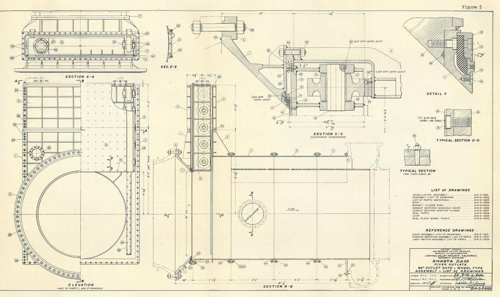
r-==,t I . . ' ,=':·· :�
S E C T I O N A - A -< 8
+
+
+
+
+
+
+
+
+
+
+
-c B
E L E VA TI O N
+
+
+
+
+
+
+
+
+
+
+ +
+ +
+ +
+ +
+ +
+ +
+ +
+ +
+ +
+
+
HALF OF PARTS J. AND � REMOVED
·· } :
""
+
+ +
+ +
+ +
+ +
,---------
S EC. E- E
20" 3• - - - - - - - - - - - -- - --- - - - - --- r------- - - -- - - - - -- - -- -- --- - - -- 194 ------- - -- - - - - - --- - -- - - - - -�
with center punch
Figure 5
32
-Lock with center punch
15
-- - - - - - - - - - ---!
:: :: ,s· +o"
·r::_-_-_-_-:::::-_-_-_-::::::::::::::::2:;. :i/ :::::::::::::::_-_-_-_:::::::: -o·
S E C T I O N C - C (CLEA RANCE D I M ENSIONS)
l, r · - - - - r
� ) \ ' I
- � ), : / !,
l=,'--c.iz:
"'zz_=_'"_=_=_ .. _=_=_ .. _=_=_ .. _=_=_"*""'_=_"'_=_=_,._=_s:,_=_=_=_,._=_.,_=_=_.::lzz:z_u_=_=_ .. _=_:z_=_=_:z_=_"_JJ,i
=
.bz=====!.--r
- j
E
FLOW
I r l
I I '.
���pz_=_=-i�4491"=
=��=====��""""'=====
�•====�===
=4r-Jr ��
,---._� I i ;: �-- - - - - - - - - - - -
30 34 30
. . . . ,· ,r .·.·••••-·• . ·••...,·.·.· •••· · • ' ':•. ����i�,l� •i ' '. ,., ,.,.- " �;z�:i,}
I I
D E TA I L X
T YPICAL SECTION D - D
TYPIC A L SEC TION THRU TAPER DOWEL U .
LIST OF DRA WINGS
INSTA L L A TION ASSEMBLY . . ASSEMBLY - LIST OF DRA WINGS. . . LIST OF PARTS - MATERIALS . . BODY . . BONNE T - FLANGE RING.
. . . . . . .. 2/4 - D· /162/
. . . . 214cD- ll622 . . . . 2/4-0-11623 . . . . 2/4 - 0 - 1 1624
. . . . 2/4-0-,1625 CONDUIT SECTIONS - MANHOLE COVER . . . . . . . . . . . 2/4-0-1/626 CONDUIT SECTION-ADAPTER FLANGE. . . . . 2/4-0- 11627 SEAL PARTS. . . 2/4-D- 1/62B LEAF . . SEAL PLATE- WHEEL - TRACK . .
. : . 2/4- D - 1 1629 . 2/4-0- 11630
R EFERENCE DRA W I NGS
HOIST-ASSEMBLY- L I S T OF DRA WINGS. . . . 214·0- /1631
POSITION INDICATOR-ASSEMBLY- LIST OF PARTS . . 214- D- //637 LIM I T SWITCH-ASSEMBLY- US T OF PARTS. . . 2/4-D- //639
U I ATES
DEPARTMENT OF THE INTERIOR BUREA U OF RECLAMATION
CENTRAL VALLEY PROJECT- CAlJFORN/A KENNETT DIVISION
S HASTA
DRAWN . . l>Y,J-!,!'( :- . l, .. L_.q.,
::;:::�
L
:.;;;� APPROVED . .

-- -Baff le
Supply 36" L D. Steel head tonk
Upstream face of dam-- - - - - - - -
Flow spreader- --
PYRA L I N S I D E/
DOWNSTREAM FRAME·. ,-A I R VE NTS f PIPE·., OR IFICE
-9.91"- -+4.74"l. - - - - 17. 06"
�--- 12. 00"- - -4<---------. 56. 44" -- - - - - - --+--- - --- 20. 1 3"
-----� i :
A PROF I L E OF MODEL INTERMEDIATE T I E R
OF I O Z. � OUTLETS
' ' ' ·
0 0 'o,
0 � � ' ' ' ' ' ' ' ' '
I
I --124 .f
PIEZOM E T E R LOCATIONS
5° 15' 30;· I : 26-17
_ _ i_tJ _____ J!I f:::=,p:=:=:::ll+i!�U!�.=.J�=�=-i.."'f-' --.�;;,- - - ---i i i-' J. I
- �� !".k- *" -, , '-41 -,--
UPSTREAM FRAME---. ,,,
,DOWNSTREAM CONDUIT UPSTREAM CONDUIT,, ,' PYAALIN
r--,-..�·,b,,-�
�,-� 00 ,;� �a. ' "' : 9
' ' ' L_
' '
"' · . a. 0 >, oo Q")e "' a. o. ,ri W ' a, I 0.2
- - ----- 5. 10 6"- -- � - -L _
Base - - -' ' ' :.C- . ------- ------- - -- ----------------- 17.06" - - - - ---- - -- - ------ - - - - - - ----- -- ----�
8 SECT ION OF GATE ASSEMBLY
SECTION AT i G ATE LEAF
·L I NE 1#:
I ' ' t<------------ ----------- --- 7
SECTION AT i i DOWNSTREAM FACE
D UPSTRE AM FRAME
' ' ,---i. ' ' :
: 9" : 9" ; rc- i6 -- ra -�
F IGURE . 6
------ - 2 .f - - - -- - - -,
' � ---- - ---- - - - - - - - - - -- ---- ---- - 7.000"
' I • : I ;�,.,..C"'-----=•.--,--'
1 "'-/N ' Q '
I ., : ' ' ' ' ' ' I
: 0. 147." "'' I
\0.5074':. -"-- --
' '
I I
0.124"
·-t!!·
17
I _1 _ _ _ 1 , I :..C- --- - - - --- - -- - - - - -- - -- - - -- - 7"- - �.717 �J
16
t UPST REAM FACE SECTION AT l E DOWNSTREAM F R A M E
C E N T R A L VA LLEY P R O J E C T - C A L I F O R N I A
S H A ST A D A M
G BASE
I • ' :...--------2¼ - - - - - --- -� F PYRA L I N SIDE
CONT R O L GATE FOR 102- INCH OUTLETS 1: 17 MODEL OF 86-I NCH GATE - OR IG INAL D E S I G N

N OT E S I . A l l data based o n 1 0 0 foot reservo i r head.
2. Pressure a nd a i r demand cu rves o re a ppro x i mate b e c a u se o f f l uctuat i o ns.
3. A i r d e m a n d based on the relation Q • C.A � Where C • 0.6, A • a rea c t 0.656"+ Or if i c e ,
a n d H . • H e a d of a i r • 1000 H., . Where H w is dete r m i n e d by P i ezometers 5 6 or 57, 58 or 59,
4. For pressures at h e a d s other than 100 feet assume pressure is proportional to the head.
- + -- _: + > P I EZOMETER LOCATIONS
= = = + )
For model details a n d piezometer Ice at ions see Figure 6 .
··-- -- -r;, , o ' a,
- · ·- -- -.,-� : o " <D
---f� , ., - --- ···r�
B. S E C T I O N A-A S H O W I N G P O S I T I O N OF S E A L R I N u a P I E Z OM E T E R S ON G A T E
A T V A R I O U S G A T E O P E N I N G S
->l ;<· o.656", Orif i ce
9 �pposit:=ii �posite . LJ 57 o s i d e e ll-Jl 59 o�i d e
. ., 0 0
.A. S E CT I O N OF M O D E L
: o ' "'
••
100
9 0
8 0
7 0
6 0
0: � 50 <{ ;:
� 4 0
t-w w "- 30
".' � 20 ::,
<I)
<I)
w 1 0 0: a.
0
- 1 0
- 30
1-----r-------... I
- I •,
' \ ' ' ,\\ \ ,\ \
\ ,,--h C,2 "" 0\ "
� � '-'
� � -------. T -1 1 --
_,2------�
, "' -------------" ,_ ' ------- "\ ';I,< ,)\ � "-.,_
------------L/ ----._� - � 6
I
\ 1M i nimum pressure - 32'--
I I I __ ---:.-r
"- __L_ -------'-
'- 0 1/ � -� -� ;----- �
\ I < ? ,�;f-- 7 -6
\ \ I 7 �
\ 'f--____ 7 5 -· I - -\- -� - ---- -- - - ---/ \ I I
\/ I
0 1 0 2 0 3 0 4 0 5 0 6 0 1, 70 8 0 9 0 / 100
0: w t-<{
9 0
80
70
60
50
;< 4 0 "-0
� 30 w "-
� 20 w 0: ::, <I) 1 0 <I)
w 0:
0
- 1 0
-30
- ----
I I
j
�� s�
H-
/ " J
5 \ \ L. b-
/)1 \ //' \
,./ I I ;'" \ I \ :?"':" 3"-'-,..---- " "-\----- I •<K\ ... - .......___ "'-1-.. �., =-4 2 '\ ,XlZ � � " .._, � """ �\ _ -;.?J-14-
�4
/ 15 --
-- - ---'- - -
\ I X \ ,l \ \ I
� \ 7�\ �
� ' �� v H--------1. I
\ I V
----
'O 1 0 2 0 3 0 - 4 0 5 0 6 0 70 80 9 0 G A T E O P E N I N G I N P E R C E N T
-- -
1 00
E. PRE S S U R E S ON D O W N ST R E AM F RA ME, BASE, A N D PYRALI N S I D E P I EZOM ETERS ( 1 3- 19, 34- 42) G A T E O P E N I N G \I N P E R c/E � T /
C. P R E S S U R E S O N u PS.I�fa'A M \F R A }.4 £--, , ;Relative pressure curves
/ , . r-- .: for hea.ds less than 100'
0:
P l E Z OM E T E R S ( 1 - 1 2 1 \...., \ /
',_j 100 r-,------=------,.=---------------,�------,--,"'-----,----- -- �--�- -�-��
�� "- .-- 2 0 _ ,
,,.--2 6 '-.
9
01
-
--+-
-
---------I'---... �n--- 1 -h--
-
-+----f I � \ - 27"
0o f-------1--+---------+�-�
\
q......_
/
---1-\---
\
..:::,.,J......\�
70 r----t---+-----lr--7+- -+--\-1-+ - -+!+--+1
1r--1----l---1
\) \ \ 6 0 1------- +---+--+---+-+---t- --------,f--------+--+----+-+--+--+- -4
� 50 1-------t-----r-----t----t-+-- -t---------,,----+--+-+-++-+--4 <{ ;: -r---..... 6 4 0 f------l--'""'--¾----- -+----++--------,---1---+--+-+-+++- -----<
; �� \ \ : 30 1----
,
-1----+--..µ....
\
_ f---+---i----1----+--+-+-----l\++-----I
� 2 0 1--------i\--- +-- +--''s+-t-- -t- --------,l-,:;-_/"
-�r--------..- "<+ -+--��--+---�
::, \ ""-_,_ _ ___,-21 -- \
; I O f-----l-�.-+---l---- ---/--l---l-r/L._�'--
f--�22
�--=i--::::�-'"4-�,l;;:=:::j:+�::,,_ _ _j � \ ,,,-------- 1L20 _
____ /� ::-- �
0 1-------:k---''t----r+--+-h+-+7==!=�::\E��"'.:'.=""�
- , o 1-----p�._.,-2•
.,::,�
"""� (��-t--=--J-t-----7"1b--/�F--_/:�r-�-/-Al+l-'/'""-l--l-;f-J
- 2 0 I "-���r\2
:. JY���v1 ll/ I
30 r------,-----,---,---,------,---�--�--� -- �--� 3.0
0: � I O 1----- -- +-----¥---+"s;;-;;,''--f----t--,I-----J- ----::::=l-....,"J:.a�""";:\-,4rl� <{ ;:: "-0 t-w w "- 0
w 0: ::, <I)
<I)
� - 10 1-------+- - ----r-tsc'"-:-+...o,,,s:--+---7'f'---f---,C7"J'Al,-;.4.�4--- -+--..j
Q.
44
- 30 1-----�- --1---+--+----+---+---- l---l---+---+---I
0 1 0 2 0 3 0 4 0 5 0 6 0 7 0 8 0 9 0 100 G A T E OP E N I N G I N P E R CENT
F IGURE 7
0: <{
>-M-p-,;-!m-ss--'-uu_":
_e ___
32'-\�-\�I! � °'-1/;v V
-30
_ I
-- - - - -• --\�
- --2t- -/----..:.::
- /4-j
Relat,ve pressure curves 0----:-.......... J.... /<------- _::.:�#" for heads less than too'
F. PRESSURES O N DOWNST R E A M CON D U I T, I N A I R VENTS a A I R D E MA N D C U RVES P I EZOM E T E RS (43
-
59)
0 1 0 ,"2.o', 3 0 1 4 0 s o s o 1 0 / \ G A T E OP E N I N G I N P E R C E NT
I \ I \ I I '-'D. P R E S S U R E S O N GATE
P l E Z O M E T ERS (20-33 )
8 0
9
0 100 C E N T R A L V A LL E Y PR O J E CT - C A L I F O R N I A
S H A S T A D A M
CONTRO L GATE FOR 1 0 2 - INCH OUTL E T S P R E S S U R E S a A I R D E M A N D FO R 1 : 1 7 MODEL O F OR IG I NA L D ES IGN

A. Gate approximately 50� open
B . Gate approximately 2 5� open
C . Gat e approximately 10% open
CONTROL GATE FOR SHASTA DAM
JET PROFILE OF 1 : 17 MODEL OF THE ORIGINAL DESIGN
Figure 8

,e- _.L_::_::,,,,_S l t I/ ' II 0 II I I
Gate Le of-,11 1 1 ,:"'-H- II
r = == = = = = = = = = = = = = 4
I
I
\ \ \
\ \
\ \ I / Unobstructed path
of Jet -
, - Contraction of J et ': a t Gate
F low
I ' I
'=- - -- - = = = �'-::: ::--
� ---=--=---fl � (..---No contract ion of Jet
at Pipe
A . Flow through a gate
B. Gate a ppr oximately 50% open . ¼hen vi ewed f rom above this j et s p reads th rough an arc of approximat ely 90 degrees .
C . Gate approximately 2 5% open
CONTROL GATE FOR SHASTA DAM
SHAPE OF JET OF COMMON GATE DESIGN
Figure 9

Gate
" I I
p-= === ===== === ==� NOTE: I n phot o g r a p h s be low Pipe D ia . 5 " I I I
O r i f ice D i a . 416" I I I '
\ I I
Unobsr ructed Pot h I of Jet-.
I I I
' ' ' I ' 0
i5 ., -� 0
I I I
I ' · 0
Flow
I --i--;r I ----- ',;
L � = = ---------------,
I
D ., 0..
Q._ i I I I I --
L e af
A . Modification of common gate design - Orifice and larger condu it u pst ream
B . Gat e approximately 50% open . Jet does not spread sidewise .
C . Gate approximately 2 5% open
CONTROL GATE FOR SHASTA DAM
IMPROVED JET WITH LARGER CONDUIT UPSTREAM AND ORIFICE AT GATE
F'igure 10

r a
l b
y--· �------�-
a: "' >-"' :i; " 0 >-3 0 z 0
' '
b 0
a: "' >-UJ � 0 UJ u u: ii: 0
t POSITION OF GATE 5 0 ¾ OPEN
l 2 5 ¾ OPEN
r , : ' 1 0 % OPEN
a: "' >-"' :i; " 0 >"'
i
F IGURE 1 1
, 1,
j ,---JET HORIZONTAL WITH GATE 1 0 0 ¾ OPEN JET DEFLECTED DOWNWARD
-I - -r --- ----------' -- AS GATE CLOSES ·_.,:
J _ _ .. . ----7r- t__VERTICAL RISE i: / 3':!=========ct=��=� (·ANGLE OF DOWNWARD -�-HORIZONTAL CLEARANCE---� DEFLECTION
4 5 ° O N 2f.1;-tTc\
4 5 °
ANGLE OF ORI FICE LIP--···
SUMMARY OF M EASUREMENTS OF PROFI L E OF BOTTOM OF J E T FOR VARI OUS APPROACH CONDUITS AND GATE OPENINGS
ALL DATA BA SED ON 1 0 0 - INCH OUT.LET DIA M ETER
J E T G ATE 5 0 % OPEN GATE 25 ¾ OPE N GATE 1 0 ¾ OPEN DIAMETER HORIZONTAL! VERTICAL ANGLE OF HORIZONTAL VERTICAL ANGLE OF HORIZONTAi
CLEARANCE! R I SE DEFLECTION CLEARANCE RISE DEFLECTION CLEARANCI
1 7 1 . 4" s1 .2" I 68" I 3. 5 " I 4° 3 5 • 2 6 " I 1 . 9 " I 6 ° 35' I 1 0 " SMOOTH JET WITH GATE 100% OPEN - LIGHT F INS AT SIDE OF JET AS GATE C L O S E S
1 7 1 . 4" 8 8 .0" 5 1 " 2 . 8 " 6 ° 4 0' 2 2" 1 . 0 " 8 ° 1 O ' 6 "
VERTICAL ANGLE OF R I S E DEFLECTION
0. 5 " I O 0 5 5 '
0 . 3 " 1 0 ° 5 5 ' 1-----+-- --+ - ---+- --+---- 1- -- � ---- --1------1-----1----+----+-- --+- --
2 a I 5° 1 5 0. 0" 8 5 .0 " 8 9 " 3 . 811 4° 3 5 ' 4
3 11
2 b 4 5° 1 50 . 0" 88 .0 " 5 0 " 2 . 6 " 6° 1 5 ' 2 2 11
3 a I 5 ° 1 3 3 . 3" 86.9" 6 7 " 3 . 6 " 5° 05 ' 3 3 "
3 b 4 5 ° 1 3 3 . 3 " 8 9. 6" 4 3 11 2. 4 " 5 ° 5 0' 2 1 "
* 4 a 1 5 ° 1 20 " 88.8" 4 9 11 3 . 0 " 6 ° 4 5' I 7 "
* 4 b 4 5 ° 1 2 0 " 9 1 . 6 " 3 3 " 2 . 0 " 7° 5 0' I 5 "
5 a I 5 ° 1 09. 1 " 9 2. 7 " 3 O " 2 . 0" 7 ° 1 5 ' ROUGH JET WITH GATE I 00 % OPE N
1 7 "
5 b 4 5 ° 1 0 9 1 " 92. 1 " I 2 s " I 1 7'' I s0 3 5' I 1 7 ,, ROUGH JET W I T H GATE 1 0 0 % OPEN
6
2 . 7 " 7 °2 0'
I. 3 11 8 ° 40'
2 . 0 " 6 °35 '
1 . 2 " 8 ° 1 O'
1 . 0 " 8 ° 30'
1 . 0 " 9 ° 1 5 '
1 . 2 " 9 ° 5 0'
1 . 0 " 1 0° 0'
1 4 "
7 "
1 2 "
6 "
6 "
6 "
1 . 0 " 7 ° O '
0 . 3 " 1 0 ° 3 0'
0 . 7 " 7 ° 3 0'
0 . 2 " 1 0 ° I 5 '
0 . 3 " 9 ° 3 0 '
0 . 2 " 1 1 ° 5 5 '
O R I F I C E 1 0 0 " 1 00 " I O " I O " _J 1 6 ° 4 5' 1 0" O" 2 1 ° 3 5 ' R E MOVED - STRAIGHT CONDUIT - ROUGH JET WITH GATE 1 00% OPEN-HEAVY F INS AT S IDES OF JET AS GATE CLOSES
* R ecommended for design
N O T E Measurements based o n model o n 6 - inct. 1 . D. pipe Accuracy of measurement s : Hor i zonta l c l earanc e ! 1 " Vert i ca l r ise! o. 2 " A n gle of def lect ion :t 0° 30 '
C E N T R A L VA LL E Y P R O J E C T - C A L I F O R N I A
S H A S T A D A M
CONTROL GATE FOR 102 - I N CH OUTLETS
JET SHAPES FOR VARIOUS GATE D E S I G N S

I I '
' • R r
· · - - -- -- ---- 100 DIVE GING SECTION - - - -- - - - - - - - - · ·;
: - - - - - - - - - .,_ --t
-T-- - -r--.... _______ _ I r
"' "' >< 0 a: a. a. <l
w 0 z w "' a: w > ci ... 0
a: w >-w 2, <l ci w 0 ;;: ii: 0
·o �
POSITION OF GATE
� s_o ¾ OPEN
� 2 5 ¾ OPEN
'
' a: w >w 2, <l ci >w 7 '
FIGURE 12
-I • , : � _ 1 0 ¾ OPEN '
'L : i
a: V ' w @J
1 1 UJ ! �JET HORIZONTAL WITH GATE 100% OPEN : i to ' �d:::====-....... -!:---·--t ·-===----==-----==-=----=-- ' __ y___�r-::--r -- --=�-=r����---b=====k============,.;;;;;:;����>;aa;��--,Jz.i '···VERTICAL RISE : ,
---- - -� - "".,;� / ANGLE OF DEFLECTI ON'
ANGLE OF ORIFICE LIP ·--_ _.--' i<-- HORIZONTAL CLEARANCE-� ', JETS DEFLECTED DOWNWARD
SUMMARY OF M EASUREMENTS OF PR OFI L E OF BOT T O M OF J E T
FOR STRAIGHT AND DIVERGING APPROACH CONDUITS
ALL DATA BASED ON 10 0- INCH OUTLET DIAM ETER
GATE 5 0 ¾ OPEN GATE 2 5 ¾ OPEN
AS GATE CLOSES
GATE 1 0 ¾ OPEN APPROACH ANGLE OF CONDUIT JET
HORIZONTAL VERTICAL ANGLE OF 1-tORIZONTAL VERTICAL ANGLE OF HORIZONTAL VERTICAL ANGLE OF CONDUIT
* STRAIGHT
t DIVERGING
STRAIGHT
DIVERGING
ORIFICE LIP DIAMETER DIAMETER CLEARANCE R I SE DEFLECTIOli CLEARANCE R I S E OEFLECTION CLEARANCE R I S E Dl':FLECTION
5 • I 2 0 " 8 8 . 8 " 4 9 " 3 . 0 " 6°4 5 ' I 7 " 1 . 0 " 8°3 0 ' 6 . 0 . 3 " 9°30 '
5 0 1 0 1 . 5 " 8 9 . 5 " 4 4 " 2. 4 " 6 °4 o · 2 o " . o " 8°3 5 ' 6 " 0 . 2 " 9°3 0 '
4 5 ° I 2 0 " 9 1 . 6 " 3 3 " 2 . 0 · 7°5 0 ' I 5 " . o · 9° I 5 ' 6 " 0 . 2 " 1 1 °5 5 '
4 5 ° 1 0 1 . 5 " 9 I . 5 " 4 I " 2 . 1 " 7°0 5 ' I 8 " 1 . 3 " I 0 °0 5 ' 8 " 0 . 3 " 1 1 °4 5 '
* Doto for straight conduit from 6" 1. D. mode l - see f i g u r e 5 t Doto for d iverg ing conduit from 4 .06 " I .D. model
CENTRAL VA LLEY PROJ E C T - CALI F OR N I A
S H A S TA D A M
CONTROL GATE FOR 1O2 - INCH OUTLETS
COM PARISON OF JET WITH STRAIGHT AND DIVERGING CONDUIT UPSTREAM

Piezometer Locotions
. ci
= a.. 0= Q N <D Q
t cS E
-� � _o a.. o= - --
� Q
'"' .:::
00
__L - "' <X>• u d�
0
0 c;l
C,
;.. 2°0Dia Orif_,.;
9" D ia. Plate ./ =� , r %'%'§"')
�
- r
..
\\\\
\\\\
\\\\�
Air demand piezometer · ··· · · ···· ·' ·
L
_.··· Existing Transition
1 " - - - - - - - - 5 .;: - - - - - - - - - :-1
-7A:
· This section odded after - - - pre liminory run- - - - · - ""i
5.88 " Trans it ion I 100·· · p��t;t-ype· · - ->i
NOT E: This edge is roundei!.
I
"' . a. C >-
� � = 0 00 '-00 a.. ,r,= , o
.J. i g I I
' ' ' , ., : � ·� . :E c , o
C :a"::
I 1 1 · I
12 14 1 5 �
· - - - - -- 4''. _ _ _ _ _ _ _ J
' ,, 2 � -
5 6
In 00 0
. � C >-Q Q
-----=----U -- t------00 � 00 a.. lf> ·o
Q
8 10 i I I 12t
;--f'>-L.c 1" ·>-< - 2'' -:"!,JC 7 3 · · - -- -· . 3" - --�
B. DESIGN 2 C I RCULAR , .. 3 ,. I 1 -<70
/'•
-?==============""f==��======="re,j ·-+ 2 .
'. 8. :�
' ' ' !-<-- - - - - - --- - - - - - - - - - af - - - - - - - - - - - - -- - - - - - -� HALF S EC. A-A
. HALF END V I E W
=., ---- --- - --·--· - ·-----·- -- - - --· oo -------�1+---- +t--t-UIII-N ------
��
I
_Jo : s - 3" · · · · - · +·
1 0 I ii LONG TRANS I T ION HALF SEC. D - 0 HALF END V I E W
40
30 a: w I-<t ;;:: u.. 0 20 I-w w u..
� w 10 a: ::, (/) (/) w a: a.
0
-10
40
30 a: w
<t ;;:: u.. 0 20 I-w w u..
� w 10 a: ::, (/) (/) w a: a.
0
ui ...:
l----+--- --JL.---+--�_+-�--,,!-c.__-- -t-- --i----t----;,V--f--j 5 u
0 10 20
10 20
�---�--- - -- -J 30 40 50 60
GATE OPE N I NG IN PERCENT 70
D. D E S I G N S H O R T T R A N S I T I O N
30 40 50 60
GATE OPENI NS IN PERCENT 70
E. D E S I G N 2 C I RCU LAR (No Tronsitionl
0
80 90 100
5
0
80 90 100
w "' a: <t :x: u (/) 0
ui ...: u w "' a: <t :x: u (/) 0
40 .....----.....-----,,---
- --,-- --,-----.--- -.---,-----,--- -- -,-----,
30 a: w
<t ;;:: u.. 0 20 I-w w u..
� w 10 a: ::, (/) (/) w a: a.
0
NOTE
All pressure-discharge curves based on 100 ft. head.
3
IQ ..
1 2 ··
-1
10 20 30 40 GATE OPENING
F. D E S I G N 3 LON G T R A N S I T I O N P R E S S U R E - D I SCHARGE CURVES
C E N T R AL VALLEY P R O J E C T - CALIFORNIA
SHASTA DAM CONTROL GATE F O R 1 0 2 - I N C H OUTLETS
90
P R E S S U R E, D I SCHA RGE A N D A I R D E MAND CURVES F O R TRANSI T IONS AND C I R CULAR SECT I O N S DOWNSTREAM FROM GAT E
ui ...: u
5 w "' a: <t :x: u (/) 0
0
100
FIGURE 13

Pigu r e 14
A . Gate 100% open
B . Gate a pp roximately 50� open
C . Ga t e app roximately 2 5% open
D . Gate approximately 10% open
CONTROL GATE FOR SHASTA DAM
JET PROFILE FROM 1 : 17 MODEL OF PROPOSED DESIGN

A . The model
B . Discharge with gate 50� open
1 : 17 MODEL OF CONTROL GATE
P ROPOSED FOR OUTLETS IN SHASTA DAM
Figure 15

A . Discha rge with gate 100% open
B . Discharge with gate 10% open
DISCHARGE THROU GH MODEL OF CONT ROL GATE
P ROPOSED FOR OUTLETS IN SHASTA DAM
rigure 16

•
, ,
-J
\ 20" Conduit -- -
�;
·Adoplor flange
96"
A
>;-< -- - 17.06" : : ' - ·>-f<· ---8B.5t'----- +- -·- · I0.56't •. > /
�To simulate : / i middle tier . ->;
,:,
& ,,�· I I /
Head ' pressure on A -(press;re en 8 - pressure on I ) since velocity head 1 n 20" conduit may be neglected . r 4�:'.?�-/
�-- -- --
' · �
�\I �o:� �:�
;Q
6"- !- -- - --
·, :., . i,' '
t-- -
, � ;E
�!it �� �,
,:002
-!mi _y ___ -
- 1 .412'' - r
-- :- 6" Dia
--: -
--0�1i1;�-����
--�:
-<- 1 91411 D � IS 0D20 FT. 2 i ' i :
�' ti
�
y
11. Air demand p1ezometer _,' '
,, �: � > ,
-· _ _ _ _ _ _ __ _. _ _ _ - - - ,a -r ----· · · - - -- - --l- - - --- elk" Transition
: 32
-------:.-··-· .
- 16 -
17 15 I
-- - 1¾"- - ->+<· - -- 2"--- - -1- - - -2"
--IN "
_ '(
PROPOSEO GATE -: --. -f' -� J EXISTING PROTOTYPE CONDUIT i ··... . -1: . ½. : �olo'srn TRANSITION SECTION i EXISTING PROTOTYPE CONDUIT
-- - -- - - --------• - - -- - ------------ ---- ----?T<- - .'3... -- -- --· >k- ------- ---------------- ---------------- --- --------- -------->t<--- --- ---------- - - - ----- --- -
I
}t,
e. T E S T e - 1 · T R A N S ITION D·o w N s T R E A M FROM GAT E
3 �- --
6
: X. � � ci �
o� -+----- -c -- -+---1---+l- o _ _ __ _
:;;_:;:: ;:; · --- - �
(Q �
Air Vent --··O.,.
C. T E S T B - 2 CON D U I T DOW N S T R E A M F RO M GAT E
A. PROFI L E OF MODE L >/' NOTE
--q]3--- -� _· Piezometer Locations
�---- ----------- , ---- --------------� HALF SEC. A-A HALF END V IEW
<
u. 0 ,-.
u.
;,: w a: ::,
a:
u
. w
;,: w a: U)
U) w a: a.
150
100
50
0 '10
0
-10
-•o
100
50
0
+10
, 9
0 16,14• ' 12
,o -10
40 ,o 60 70 GATE OPENING IN PERCENT
D_ TEST B - 1 T R AN S I T I O N
See curves above for Air Demond, Head, ond piezometers I a 2 .
----- 1, ----
80 90
.,.....A-- This pietometer woa __ .,,.. found defective.
F IGURE 17
U) .: 0
< w 0
100
Approx. error"' -0.02,fo, -20 o'c-- ----,1Lo---�,"'o�--·-=',o 40 ,0 60 70 80 90 100
GATE OPENING IN PERCENT
E. T E S T B - 2 C I R CULAR CON D U I T
P R E S S U R E - A I R D EM A N D CURVES
CEN TRAL VA LLEY PROJ E C T - CA L I FORNIA
S HASTA DAM
CONTROL GATE FOR 1 O 2 - I NCH OUTLETS
PRESS U R E AND A I R DEMA ND C URVES FOR H I GH HEAD TESTS
1 : 1 7 MODELS OF PROPOSED GATE

0
� · ---· � r \ -+l+---+-ll--l+H-t-
g >--- -- -----< -� 1
!;; -9.91 ''. .,_;.4_74;.;.. . - - - - 17. 06" - - - - - --- - - - 88.57'' · · · · • . .
, , ' ' ' ',
f.,- - - - - - 6"- - - - - -�
i<.- - - - - - -- - -
-
- - - · · -- a" Dia. --- - - - - - - - - - - · - :,,...
Orifice area , : : :g ·>-: 1.914 D ia . :-c - 0.0200 ft' : : 0 ! i : IY,f'@P,?'��� (/////,17/(A
T° : Air demand p,ezometer .: :
• .L" A ir vent on each s ,de , • 2 Orifice area , 0 0033 ft
1 ¾" - + - - 2f - · · '1 5
<:-:; . . A i r v e n t - - ·"
- · ·1
· 11)
-
- - -.- - - - 1 oi"- - - - - - - - - - - - - - - - - - - - , a. . �
0 -
- -- - 0 �-___t_ ' 0 "' a:: ;iote , Pi�zometers 16, 17, 18, 19,
and 20 shown for side in this view, near s ide i n other views
I- ' z , W , > , er ' <( ' <!> ' z ,
� : x , W ,
2 1 2 2 " " " . " � 1 ¾ - -+ - - 2" - - -+- -- 2" - - - -+- - 1 r - -+ 1" + - - 2" - -+ - 3" -,J
EX IST I N G PROTO T Y P E CON D U I T , PROPOSED GATE AN D CON D U I T : EX I ST I N G P.ROTOTY P E C O N D U I T
. • • • • • - • • • • • • - • • • • • • • - • • - • •.
• - ->,<- - - •
-
• • • -.
- - - - - - - - -;j � - - - - - - . . - - . - . . - - . - - . - - - - -- - - - - ->;<- . - - . .
. - - - . - - - . - .
.. .
E L E V AT I O N
B. D E T A I L S O F G A T E
A. P R O F I L E
N O T E
--=IP- + Piezometer Locations
:.- -To st imulote middle t ier
O F M O D E L
H A L F S EC. A - A H A L F E N D V I E W
' ·Jc-
Gone ·· ,,., . <,·
• <:,' "-"' ., ..
Note s •
90 1-----\�--l--- ----+-
' DISCHARGE
F I GURE 18
80 - --+ - - - --+ 0 0.8
70
---j 60 Cl'. w f-
u. 0 50 f-w w u. z w 40 Cl'. ::, A I R D E M A N D O F <11 <11 w Cl'. a. 30
0 "' "' z 0 " "' a, 0 "' :! a, 0 ? T ----- _; 0 ' -· I I
Base pressure i n gote, piezometet·6' ··· - , 0 0 10 20 30 40 50 60 70 GI\TE OPE N I N G I N PERCENT
C. P R E SS U R E - DI SC H A R G E C U R V E S
( I ) A l I pressure - d i schorge curves based on 100 ft. head (2 ) Model heads approximately 50 ft. except at 100% open (3) At 100% open mode head 16.9 ft. ( Scale head ' 13.1 f t ) ( 4) The coefficient of d ischarge "c" is based on the rela-
tion C , __g__ where O ' d ischarge , A , the area of A\/'2g'H
the condu i t , and H , the reservoir head o bove the valve 't.
C E N T R A L V A L LEY P R O J E CT - CALIFORNIA
S H A STA DAM
� 6 '
80
CONTROL GATE FOR 1 0 2 - INCH OUTLETS PRES S U RE, D I S CHARGE AND A I R DEMAND CURVES
1 : 1 7 M O D E L OF T H E FINAL DESIGN
.,. ... 6 0 ' '
·--Piez.• 4 .f
0.7
6 0.6 D
w <( Cl :; 0: w " D I
5 0: (.)
O .S <J> <( 0 D u. z 0 <( >-z
4 w 0.4 w
2
0
Cl -� 0: <( u. I u. (.) w <11 0 0 (.)
0. 3
0.2
0. 1
0 3, 4,5, 7, 8 ,9,
1 1, 13 , 14
90 100

" .. �
A . Gate 10% open B. Gate 2 5% open
PROPOSED CONTROL GATE DISCHARGING INTO A STILLING POOL
AT GATE OPENINGS OF 10 and 25 PERCENT "'l f-" °" C: .., en I-' '°

"' . •
A. Gate 50% open B. Gate 100% open . Note waves on sidewalls because of low head
PROPOSED CONTROL GATE DISCHARGING INTO A STILLING POOL
AT GATE OPENINGS OF 50 and 100 PERCENT "'l ,_.. Oil C: '1 (1)
N 0

'> •
A . Gate 50% open B. Gate 100% open
PROPOSED CONTROL GATE DISCHARGING INTO A STILLING POOL
WAVES ON SIDEWALLS ELIMINATED BY UNDERCUT PIERS
..
..,,, ..... (7Q i:; '"1 Cl)
N I-'

Figure 22
A . Gate 100� open
B. Gate 2 5� open
PROPOSED CONTROL GATE USING SQUARE-TYPE ORIFICE


![Catalogue Needle Valve[1]](https://img.pdfslide.net/doc/110x75/577cd8241a28ab9e78a0818f/catalogue-needle-valve1.jpg)