Embed Size (px)
Citation preview
14th ANNUAL THERMAL & FLUIDS
ANALYSIS WORKSHOP
August 21, 2003Vince Rausch757-864-3736
The Hyper-X Program
2
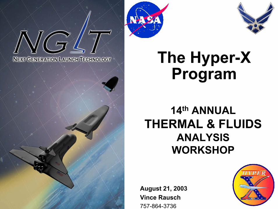
Enabling Technologies for Hypersonic SystemsEnabling Technologies for Hypersonic Systems
Mach<4 Mach 4-12
High Speed missile
Rocket Boost
H/C “axi”missile
Rocket BoostWaverider or Lifting BodySupersonic
Cruise Missile
Long Range Weapon-Strike -Intercept
Mid Range Weapon-Strike
ReusableReusable
Mach 0-7 Mach 0-15
Hydrocarbon fueled
Combined Cycle
Long Range Strike
Hydrogen-fueledCombined Cycle
Responsive Space Access
Enabling Technologies•Long Life, High
Temperature Materials
•High Speed Aero/thermo-
dynamics
•Thermal Protection
•High-Speed Turbine
•Hydrogen Scramjet
•Hydrocarbon Scramjet
•Combined Cycles (RBCC/TBCC)
Capabilities
Demonstrations
Flight Regimes
Rocket Boost
H2 “axi”missile
Mid Range Weapon-Strike -Intercept
ExpendableExpendable
THERMAL & FLUIDS ANALYSIS REQUIRED FOR ALL!
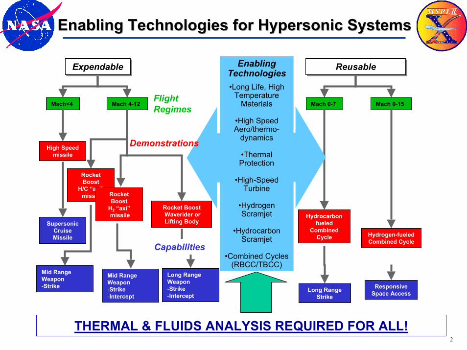
XXX---43A43A43A
4
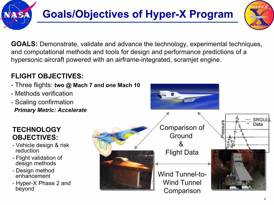
Goals/Objectives of Hyper-X Program
Wind Tunnel-to-Wind TunnelComparison
Comparison ofGround
& Flight Data
GOALS: Demonstrate, validate and advance the technology, experimental techniques, and computational methods and tools for design and performance predictions of a hypersonic aircraft powered with an airframe-integrated, scramjet engine.
FLIGHT OBJECTIVES:- Three flights: two @ Mach 7 and one Mach 10- Methods verification- Scaling confirmationPrimary Metric: Accelerate
TECHNOLOGYOBJECTIVES:- Vehicle design & riskreduction
- Flight validation ofdesign methods
- Design methodenhancement
- Hyper-X Phase 2 and beyond
5
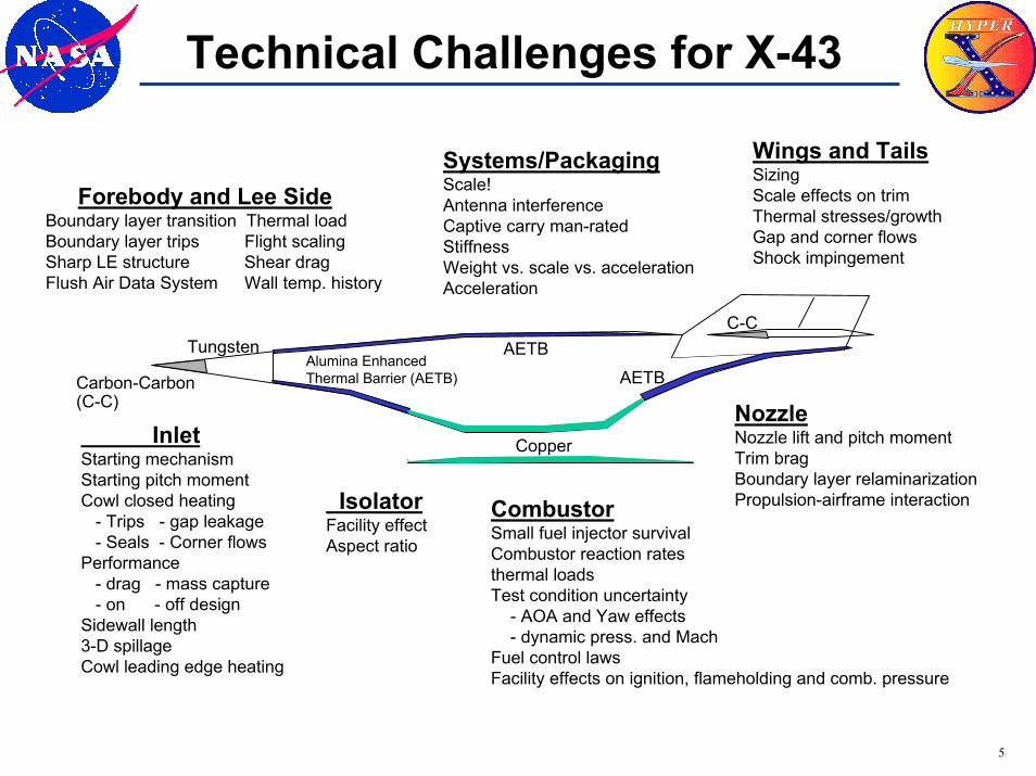
Technical Challenges for X-43
Wings and TailsSizingScale effects on trimThermal stresses/growthGap and corner flowsShock impingement
Inlet Starting mechanismStarting pitch momentCowl closed heating
- Trips - gap leakage- Seals - Corner flows
Performance- drag - mass capture- on - off design
Sidewall length3-D spillageCowl leading edge heating
CombustorSmall fuel injector survivalCombustor reaction ratesthermal loadsTest condition uncertainty
- AOA and Yaw effects- dynamic press. and Mach
Fuel control lawsFacility effects on ignition, flameholding and comb. pressure
NozzleNozzle lift and pitch momentTrim bragBoundary layer relaminarizationPropulsion-airframe interaction
Tungsten
Copper
AETBAlumina Enhanced Thermal Barrier (AETB) AETBCarbon-Carbon
(C-C)
C-C
Isolator Facility effectAspect ratio
Systems/PackagingScale!Antenna interferenceCaptive carry man-ratedStiffnessWeight vs. scale vs. accelerationAcceleration
Forebody and Lee SideBoundary layer transition Thermal loadBoundary layer trips Flight scalingSharp LE structure Shear dragFlush Air Data System Wall temp. history
6
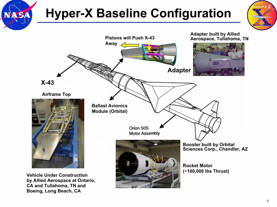
Hyper-X Baseline Configuration
X-43A
Adapter
Booster built by Orbital Sciences Corp., Chandler, AZ
Rocket Motor (~100,000 lbs Thrust)
Ballast Avionics Module (Orbital)
X-43
Pistons will Push X-43 Away
Airframe Top
Adapter built by Allied Aerospace, Tullahoma, TN
Vehicle Under Construction by Allied Aerospace at Ontario, CA and Tullahoma, TN and Boeing, Long Beach, CA
7
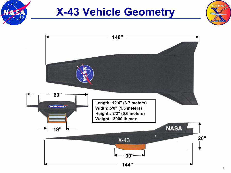
X-43 Vehicle Geometry
148"
30"
19"26"
60"Length: 12'4" (3.7 meters)Width: 5'0" (1.5 meters)Height:: 2'2" (0.6 meters)Weight: 3000 lb max
144"
8
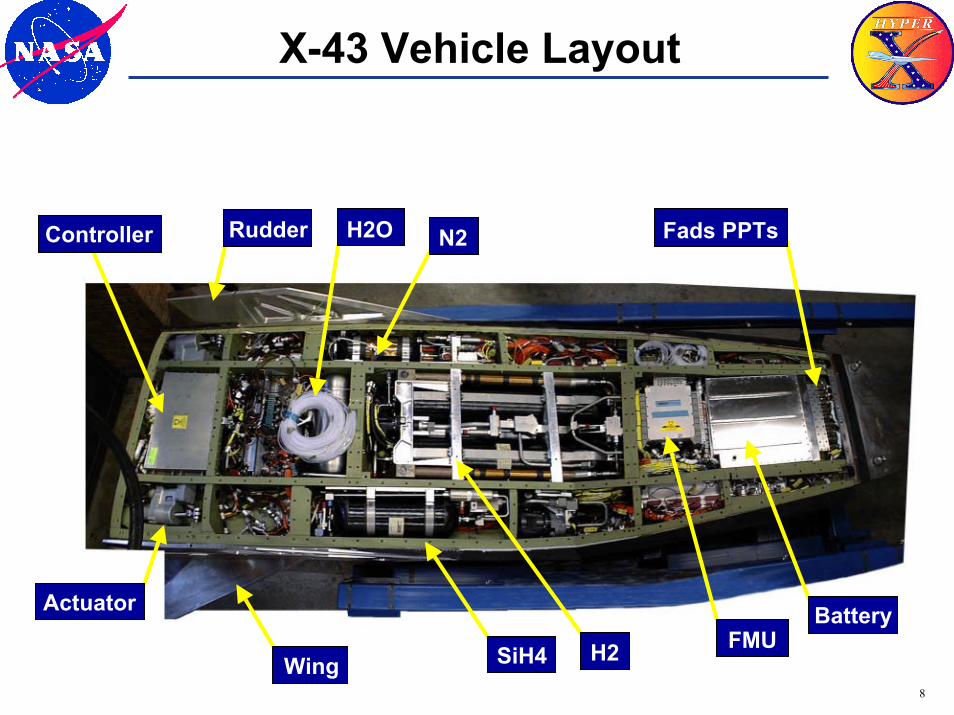
X-43 Vehicle Layout
Rudder N2 Controller Fads PPTs H2O
Wing H2Battery
FMU Actuator
SiH4
9
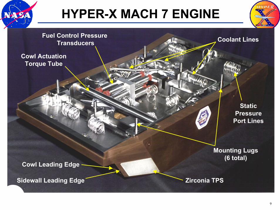
HYPER-X MACH 7 ENGINE
Cowl ActuationTorque Tube
Fuel Control Pressure Transducers Coolant Lines
Mounting Lugs(6 total)
Static Pressure
Port Lines
Cowl Leading Edge
Sidewall Leading Edge Zirconia TPS
10
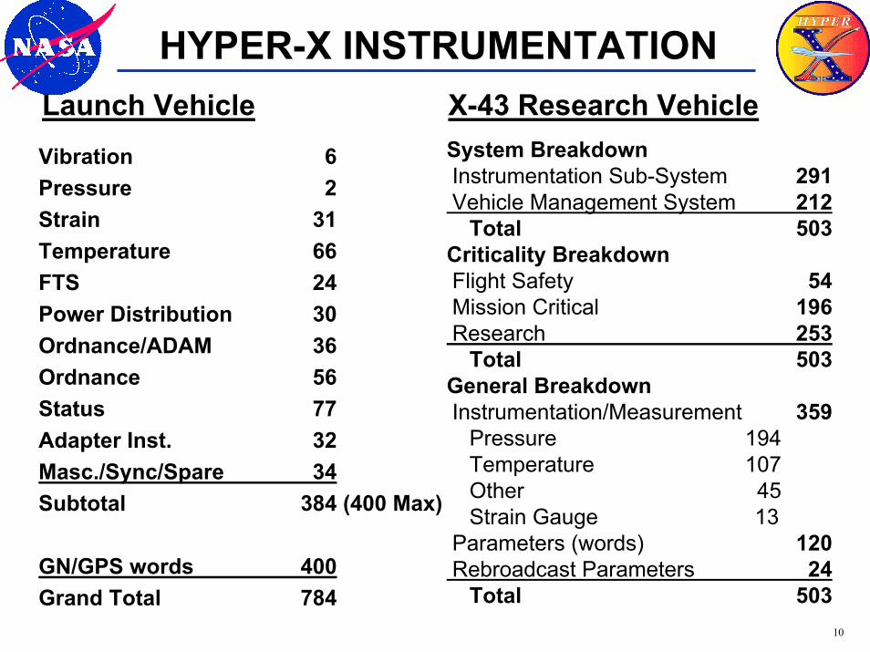
HYPER-X INSTRUMENTATIONLaunch Vehicle X-43 Research Vehicle
System BreakdownInstrumentation Sub-System 291Vehicle Management System 212
Total 503Criticality BreakdownFlight Safety 54Mission Critical 196Research 253
Total 503General BreakdownInstrumentation/Measurement 359
Pressure 194Temperature 107Other 45Strain Gauge 13
Parameters (words) 120Rebroadcast Parameters 24
Total 503
Vibration 6Pressure 2Strain 31Temperature 66FTS 24Power Distribution 30Ordnance/ADAM 36Ordnance 56Status 77Adapter Inst. 32Masc./Sync/Spare 34Subtotal 384 (400 Max)
GN/GPS words 400 Grand Total 784
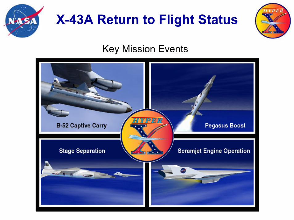
X-43A Return to Flight Status
Key Mission Events
12
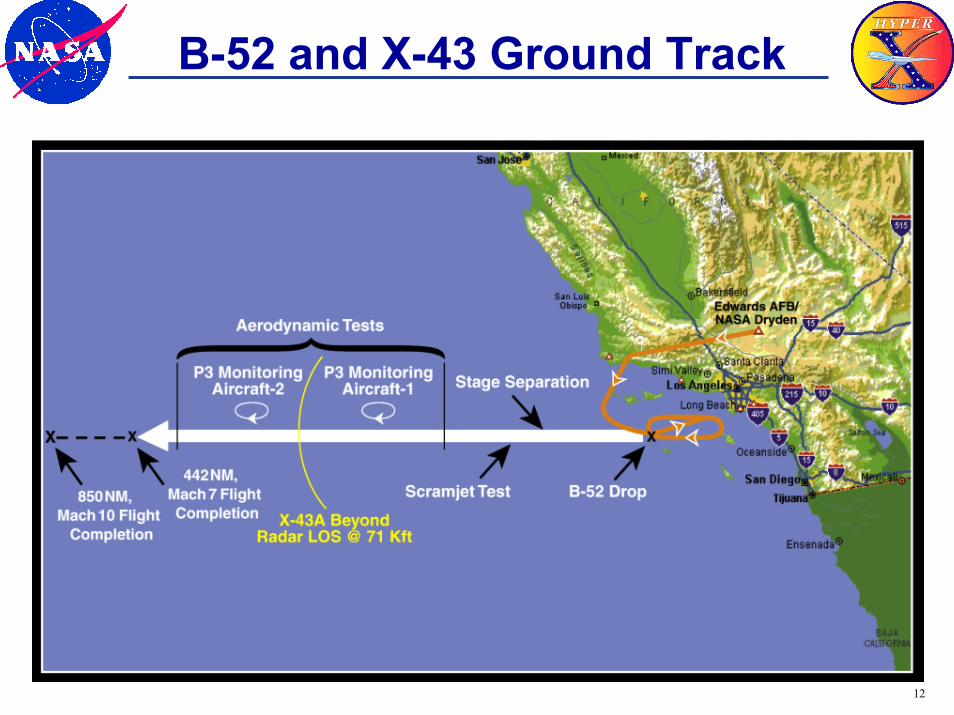
B-52 and X-43 Ground Track
13
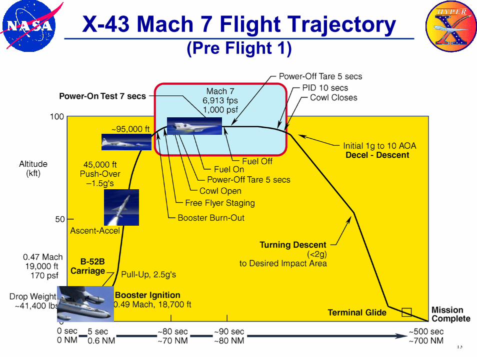
X-43 Mach 7 Flight Trajectory(Pre Flight 1)
14
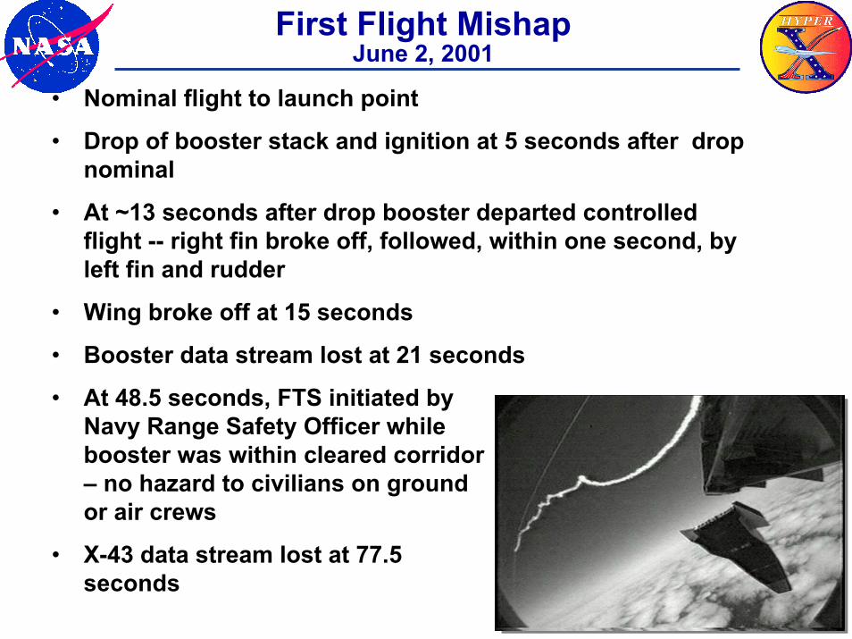
First Flight MishapJune 2, 2001
• Nominal flight to launch point
• Drop of booster stack and ignition at 5 seconds after drop nominal
• At ~13 seconds after drop booster departed controlled flight -- right fin broke off, followed, within one second, by left fin and rudder
• Wing broke off at 15 seconds
• Booster data stream lost at 21 seconds
• At 48.5 seconds, FTS initiated by Navy Range Safety Officer while booster was within cleared corridor – no hazard to civilians on ground or air crews
• X-43 data stream lost at 77.5 seconds
15
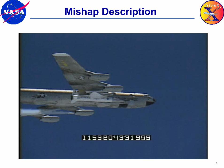
Mishap Description
16
X-43A Return to Flight
• X-43A Mishap Investigation Board (MIB) was convened on June 5, 2001 and submitted its draft report March 8, 2002
• Report released July 23, 2003• Return to Flight (RTF) commenced in March
2002 with development of:– Corrective Action Plan in response to the MIB
findings/recommendations– Overall approach/roadmap for Return to Flight
17
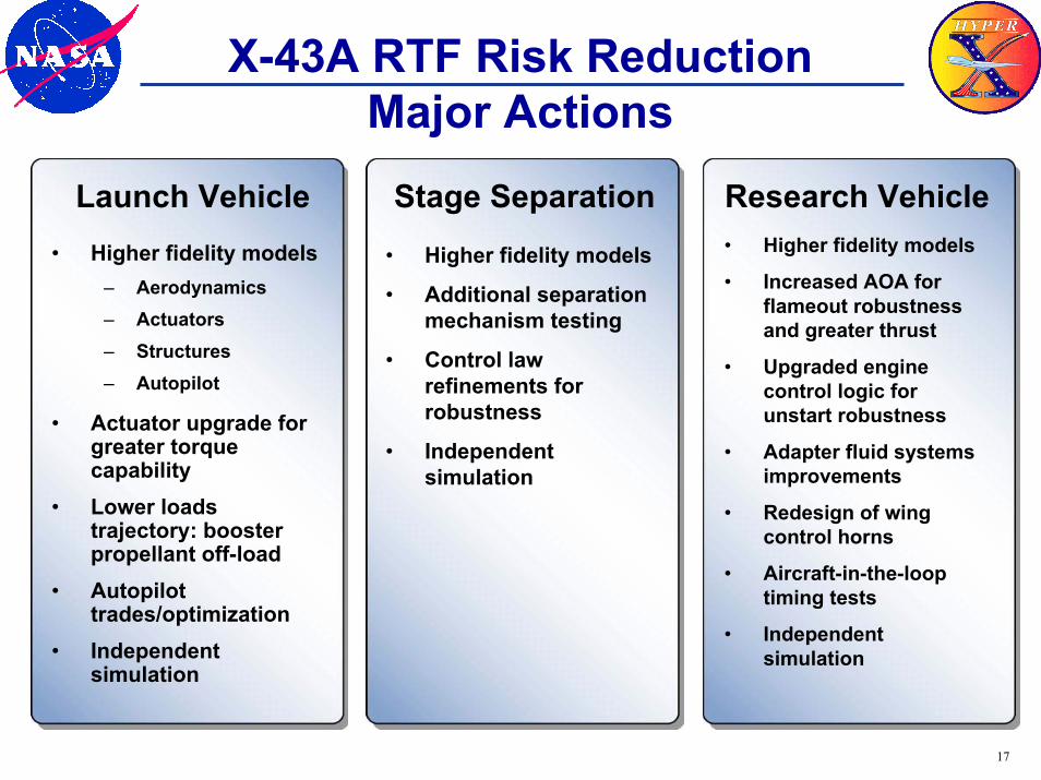
X-43A RTF Risk ReductionMajor Actions
• Higher fidelity models– Aerodynamics– Actuators– Structures– Autopilot
• Actuator upgrade for greater torque capability
• Lower loads trajectory: booster propellant off-load
• Autopilot trades/optimization
• Independent simulation
• Higher fidelity models
• Additional separation mechanism testing
• Control law refinements for robustness
• Independent simulation
• Higher fidelity models
• Increased AOA for flameout robustness and greater thrust
• Upgraded engine control logic for unstart robustness
• Adapter fluid systems improvements
• Redesign of wing control horns
• Aircraft-in-the-loop timing tests
• Independent simulation
Launch Vehicle Stage Separation Research Vehicle
18
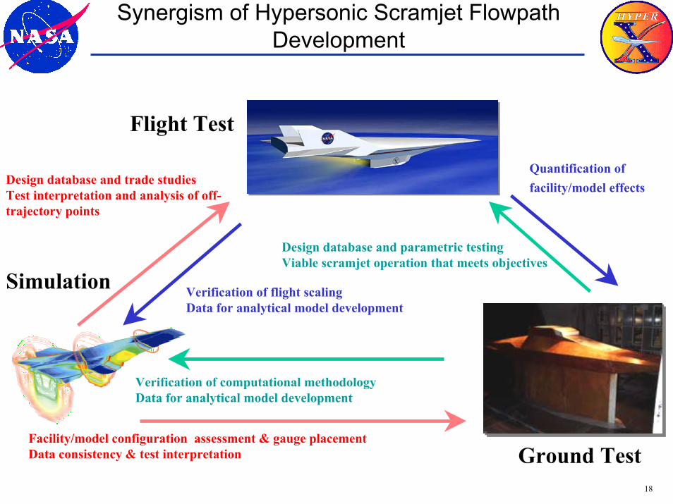
Synergism of Hypersonic Scramjet FlowpathDevelopment
Simulation Verification of flight scalingData for analytical model development
Design database and trade studiesTest interpretation and analysis of off-trajectory points
Quantification of facility/model effects
Verification of computational methodologyData for analytical model development
Design database and parametric testingViable scramjet operation that meets objectives
Flight Test
Facility/model configuration assessment & gauge placementData consistency & test interpretation Ground Test
19
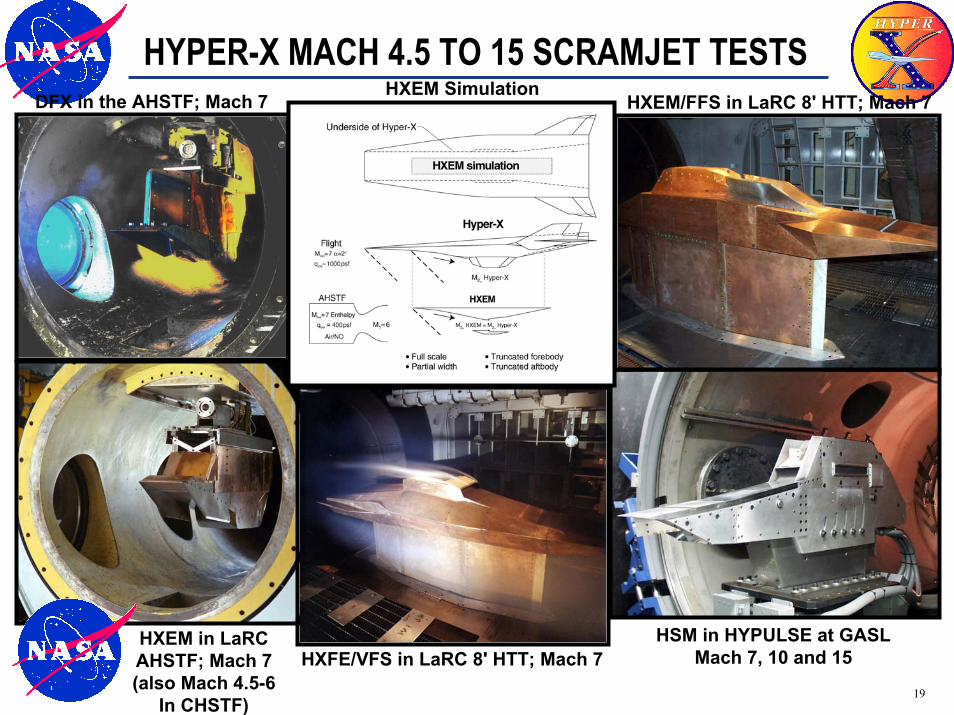
HYPER-X MACH 4.5 TO 15 SCRAMJET TESTS
HXEM in LaRCAHSTF; Mach 7(also Mach 4.5-6
In CHSTF)
HXEM SimulationDFX in the AHSTF; Mach 7 HXEM/FFS in LaRC 8' HTT; Mach 7
HSM in HYPULSE at GASLMach 7, 10 and 15HXFE/VFS in LaRC 8' HTT; Mach 7
20
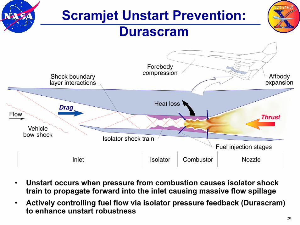
Scramjet Unstart Prevention:Durascram
• Unstart occurs when pressure from combustion causes isolator shock train to propagate forward into the inlet causing massive flow spillage
• Actively controlling fuel flow via isolator pressure feedback (Durascram) to enhance unstart robustness
21
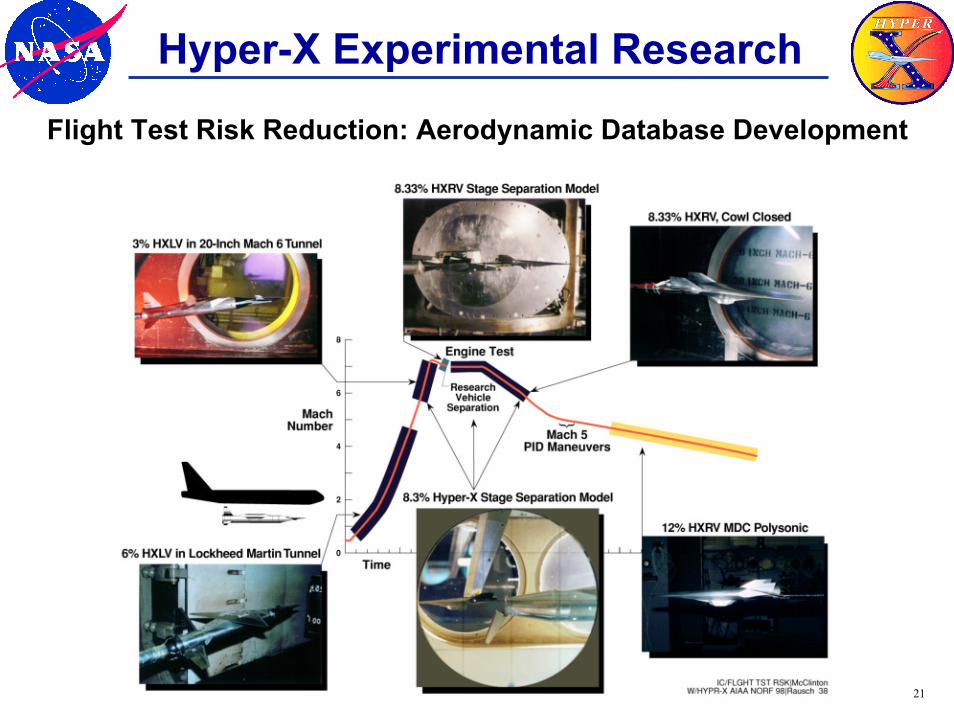
Hyper-X Experimental ResearchFlight Test Risk Reduction: Aerodynamic Database Development
22
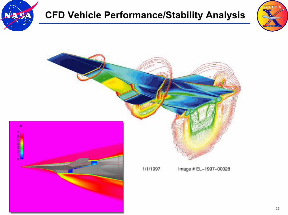
CFD Vehicle Performance/Stability Analysis
23
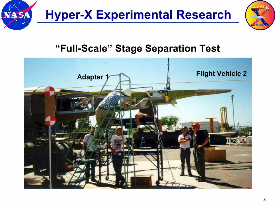
Hyper-X Experimental Research
“Full-Scale” Stage Separation Test
Flight Vehicle 2Adapter 1
24
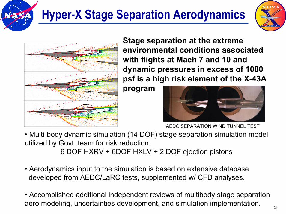
Hyper-X Stage Separation Aerodynamics
• Multi-body dynamic simulation (14 DOF) stage separation simulation model utilized by Govt. team for risk reduction:
6 DOF HXRV + 6DOF HXLV + 2 DOF ejection pistons
• Aerodynamics input to the simulation is based on extensive databasedeveloped from AEDC/LaRC tests, supplemented w/ CFD analyses.
• Accomplished additional independent reviews of multibody stage separation aero modeling, uncertainties development, and simulation implementation.
Stage separation at the extreme environmental conditions associated with flights at Mach 7 and 10 and dynamic pressures in excess of 1000psf is a high risk element of the X-43A program
AEDC SEPARATION WIND TUNNEL TEST
25
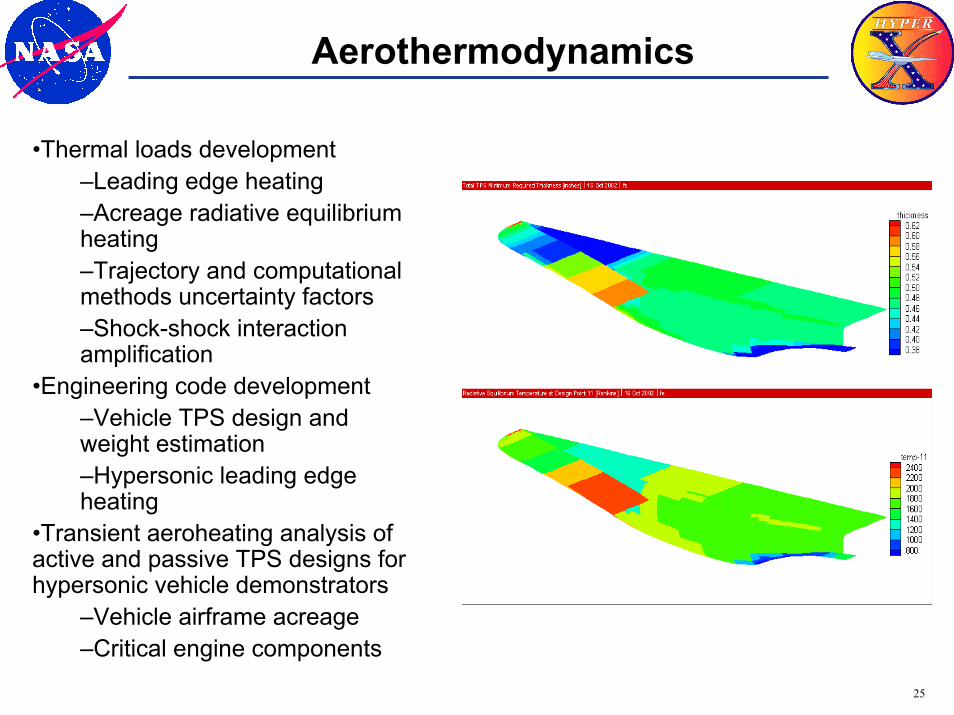
Aerothermodynamics
•Thermal loads development–Leading edge heating–Acreage radiative equilibrium heating–Trajectory and computational methods uncertainty factors–Shock-shock interaction amplification
•Engineering code development–Vehicle TPS design and weight estimation–Hypersonic leading edge heating
•Transient aeroheating analysis of active and passive TPS designs for hypersonic vehicle demonstrators
–Vehicle airframe acreage–Critical engine components
26
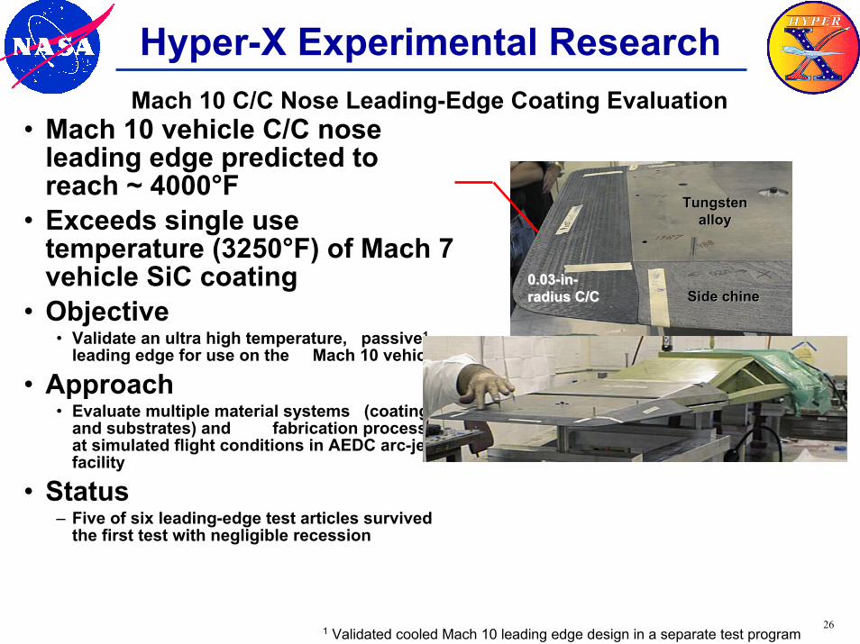
Hyper-X Experimental Research
• Mach 10 vehicle C/C nose leading edge predicted to reach ~ 4000°F
• Exceeds single use temperature (3250°F) of Mach 7 vehicle SiC coating
• Objective• Validate an ultra high temperature, passive1,
leading edge for use on the Mach 10 vehicle
• Approach• Evaluate multiple material systems (coatings
and substrates) and fabrication processes at simulated flight conditions in AEDC arc-jet facility
• Status– Five of six leading-edge test articles survived
the first test with negligible recession
Side chineSide chine
TungstenTungstenalloyalloy
0.030.03--inin--radius C/Cradius C/C
Mach 10 C/C Nose Leading-Edge Coating Evaluation
1 Validated cooled Mach 10 leading edge design in a separate test program
27
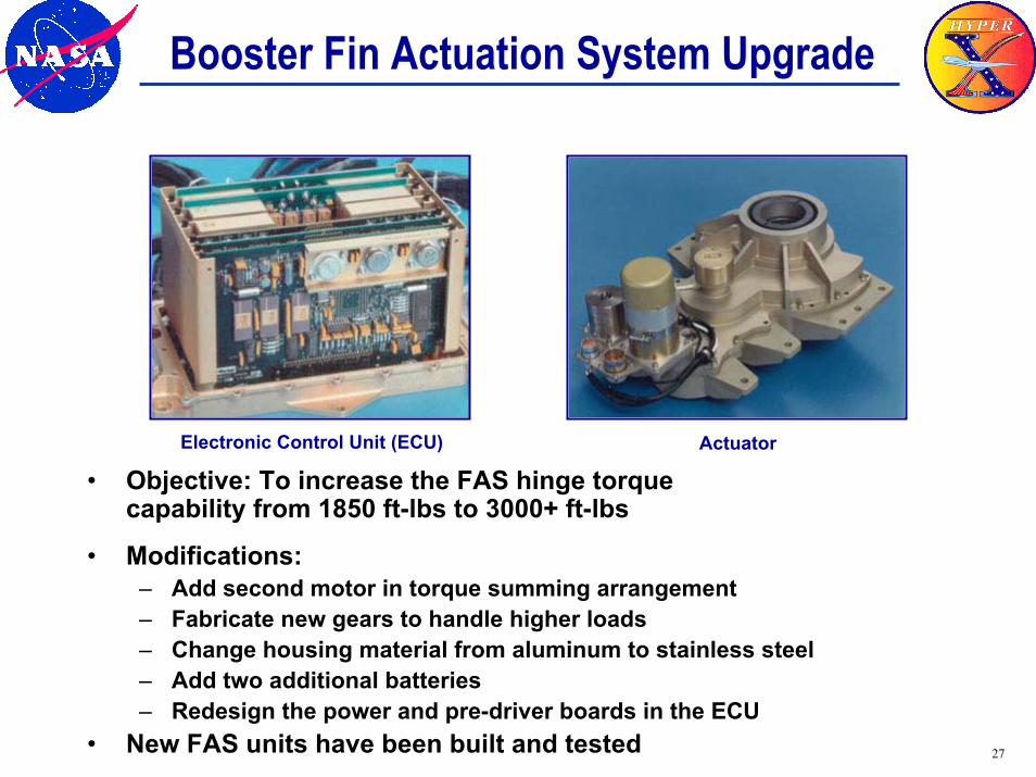
Booster Fin Actuation System Upgrade
Electronic Control Unit (ECU) Actuator
• Objective: To increase the FAS hinge torque capability from 1850 ft-lbs to 3000+ ft-lbs
• Modifications:– Add second motor in torque summing arrangement– Fabricate new gears to handle higher loads– Change housing material from aluminum to stainless steel– Add two additional batteries– Redesign the power and pre-driver boards in the ECU
• New FAS units have been built and tested
28
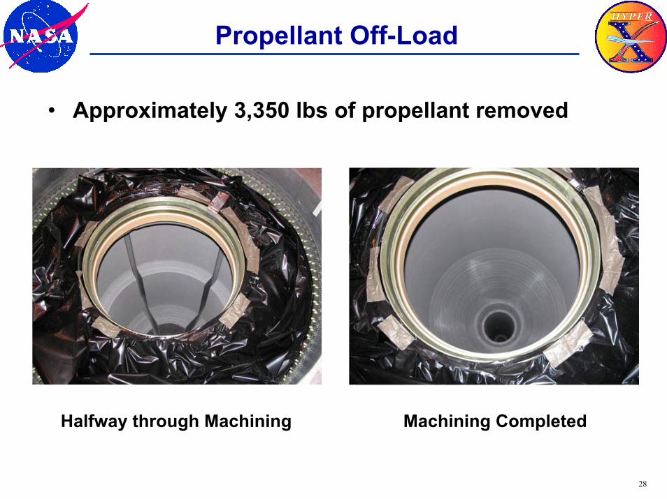
Propellant Off-Load
• Approximately 3,350 lbs of propellant removed
Halfway through Machining Machining Completed
29
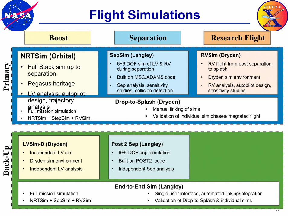
Flight Simulations
NRTSim (Orbital)• Full Stack sim up to
separation• Pegasus heritage• LV analysis, autopilot
design, trajectory analysis
Boost Separation Research Flight
SepSim (Langley)• 6+6 DOF sim of LV & RV
during separation• Built on MSC/ADAMS code• Sep analysis, sensitivity
studies, collision detection
RVSim (Dryden)• RV flight from post separation
to splash• Dryden sim environment• RV analysis, autopilot design,
sensitivity studies
• Full mission simulation• NRTSim + StepSim + RVSim
• Manual linking of sims• Validation of individual sim phases/integrated flight
Drop-to-Splash (Dryden)
LVSim-D (Dryden)• Independent LV sim• Dryden sim environment• Independent LV analysis
Post 2 Sep (Langley)• 6+6 DOF sep simulation• Built on POST2 code• Independent Sep analysis
• Full mission simulation• NRTSim + SepSim + RVSim
• Single user interface, automated linking/integration• Validation of Drop-to-Splash & individual sims
End-to-End Sim (Langley)
Prim
ary
Bac
k-U
p
30
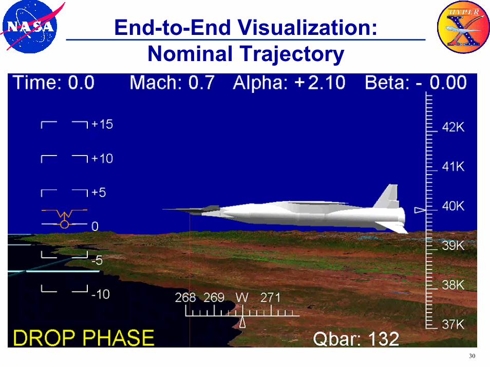
End-to-End Visualization:Nominal Trajectory
31
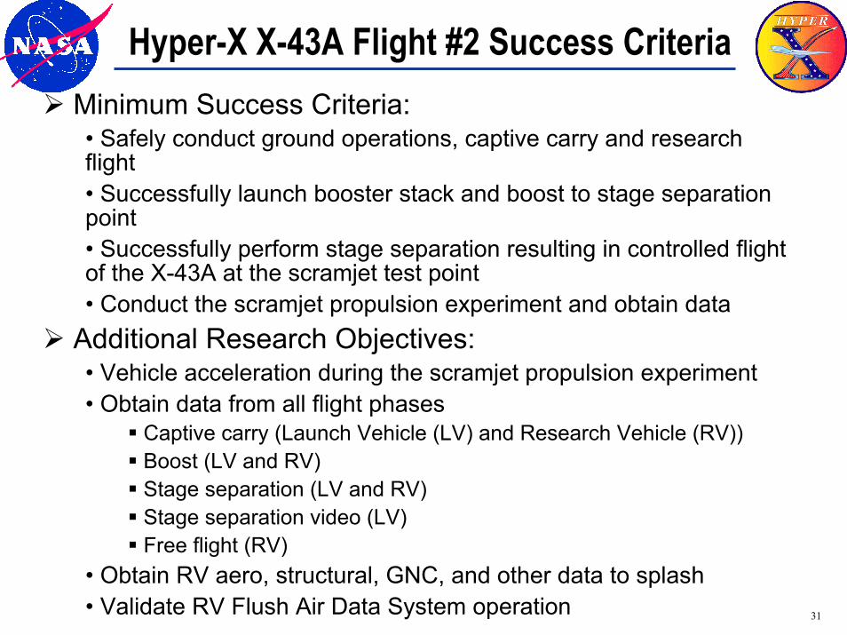
Hyper-X X-43A Flight #2 Success CriteriaMinimum Success Criteria:• Safely conduct ground operations, captive carry and research flight• Successfully launch booster stack and boost to stage separationpoint• Successfully perform stage separation resulting in controlled flight of the X-43A at the scramjet test point• Conduct the scramjet propulsion experiment and obtain data
Additional Research Objectives:• Vehicle acceleration during the scramjet propulsion experiment• Obtain data from all flight phases
Captive carry (Launch Vehicle (LV) and Research Vehicle (RV))Boost (LV and RV) Stage separation (LV and RV) Stage separation video (LV)Free flight (RV)
• Obtain RV aero, structural, GNC, and other data to splash• Validate RV Flush Air Data System operation
32
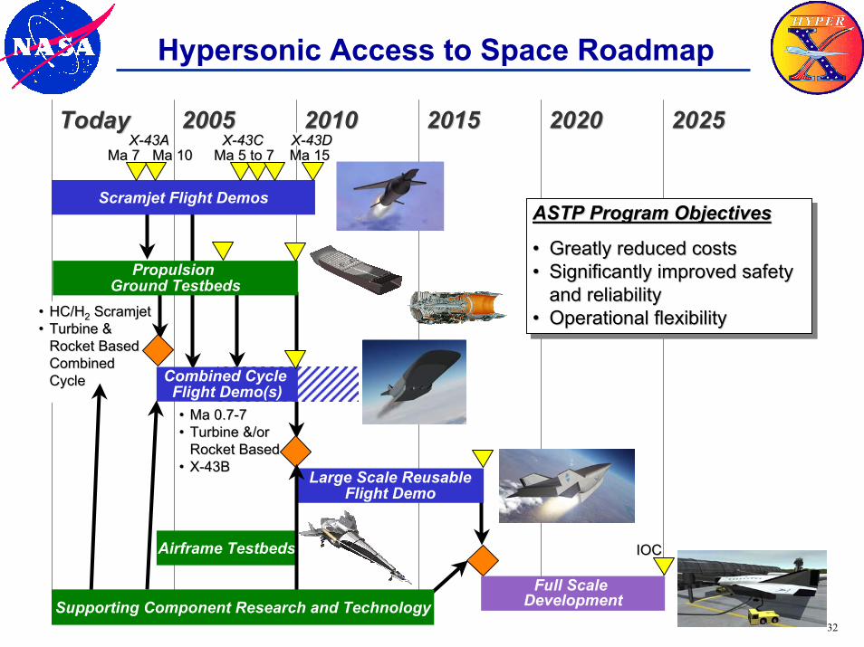
Hypersonic Access to Space Roadmap
TodayToday 20052005 20102010 20152015 20202020 20252025
Propulsion Ground Testbeds
Combined Cycle Flight Demo(s)
Scramjet Flight Demos
Ma 7Ma 7
•• Ma 0.7Ma 0.7--77•• Turbine &/or Turbine &/or
Rocket BasedRocket Based•• XX--43B43B
Large Scale ReusableFlight Demo
Full Scale Development
Ma 5 to 7Ma 5 to 7 Ma 15Ma 15
Airframe Testbeds
Supporting Component Research and Technology
ASTP Program ObjectivesASTP Program Objectives
•• Greatly reduced costsGreatly reduced costs•• Significantly improved safety Significantly improved safety
and reliabilityand reliability•• Operational flexibilityOperational flexibility
IOCIOC
Ma 10Ma 10XX--43A43A XX--43C43C XX--43D43D
•• HC/HHC/H22 ScramjetScramjet•• Turbine & Turbine &
Rocket BasedRocket BasedCombinedCombinedCycleCycle
33
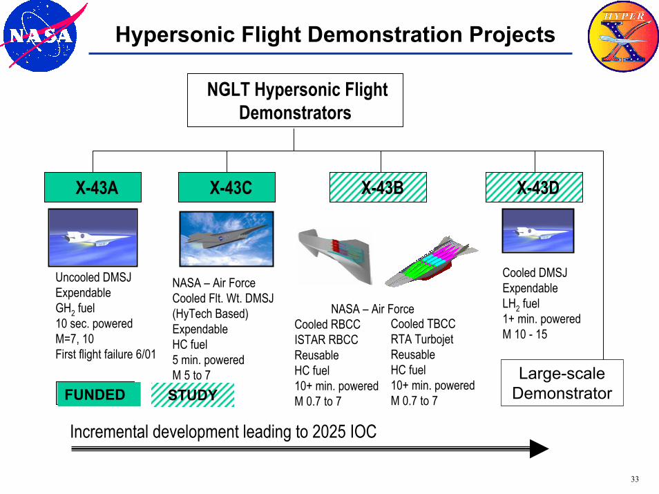
Hypersonic Flight Demonstration Projects
Cooled RBCCISTAR RBCCReusableHC fuel10+ min. poweredM 0.7 to 7
Cooled TBCCRTA TurbojetReusableHC fuel10+ min. poweredM 0.7 to 7FUNDED STUDY
NASA – Air Force
NGLT Hypersonic FlightDemonstrators
Incremental development leading to 2025 IOC
X-43A X-43C X-43B X-43D
Cooled DMSJExpendableLH2 fuel1+ min. poweredM 10 - 15
Uncooled DMSJExpendable GH2 fuel10 sec. poweredM=7, 10First flight failure 6/01
NASA – Air ForceCooled Flt. Wt. DMSJ(HyTech Based)Expendable HC fuel5 min. poweredM 5 to 7 Large-scale
Demonstrator
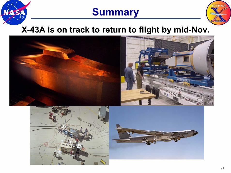
34
SummaryX-43A is on track to return to flight by mid-Nov.