Embed Size (px)
Citation preview

ISABE-2017-MANUSCRIPT NUMBER 1
ISABE 2017
The Impact of Clean Sky Technology on
Future 3500 lb Single Engine Light
Rotorcraft
J. Enconniere, J. Ortiz-Carretero, I. Goulos and V. Pachidis
Cranfield University
Centre for Propulsion Engineering, School of Aerospace, Transport and Manufacturing
Cranfield
Bedfordshire
C. Smith
Leonardo Helicopters
UK
J. Stevens
Netherlands Aerospace Centre, NLR
The Netherlands
R. d’Ippolito
NOESIS Solutions N.V.
Belgium
L. Thevenot
Airbus Helicopters
France
ABSTRACT This manuscript describes a collaborative research effort between members of the Clean Sky Joint Technology
Initiative (JTI), within the broader area of novel rotorcraft engine technology and rotorcraft operations. The
Clean Sky JTI was created as a public/private partnership between the European Commission and the
aeronautical industry. The paper assesses the impact of innovative engine technologies to be integrated into the
next generation of rotorcraft and evaluates their potential towards meeting the ACARE 2020 goals. The focus is
on the lower segment of the light helicopter class with a particular interest in the performance of two innovative
powerplants: an advanced turboshaft with Lean Premixed Prevaporised (LPP) combustor design and a
supercharged diesel cycle engine. In order to evaluate their benefits alongside other Clean Sky technologies, a
multi-disciplinary rotorcraft performance analysis framework (PhoeniX) is employed. Two variants of the same
light helicopter platform with year 2020 technology plus Clean Sky innovations are modelled, named hereafter
as Single Engine Light (SEL) Y2020 and High Compression Engine (HCE) Y2020, respectively. A turboshaft
engine-powered helicopter, representative of year 2000 technology (SEL Y2000) is also modelled and used as
reference. Payload-Range diagrams (PR) of the three vehicles were generated. The HCE Y2020 reached a
maximum range 83% greater than the SEL counterparts. The gaseous emissions of the helicopters were also
evaluated over three notional scenarios representative of light helicopter activities. The HCE Y2020 emitted
60% less carbon dioxide (CO2) and 63% less nitrogen oxides (NOx) than the SEL Y2000. The SEL Y2020
emitted on average 19% and 49% less CO2 and NOx, respectively, compared with the SEL Y2000. It was also
observed that the NOx production rate of the LPP technology integrated in the SEL Y2020 combustor depends
strongly on engine power setting. At certain power settings, the SEL Y2020 emitted less NOx than the HCE
Y2020 even though the HCE Y2020 emitted less NOx over the complete mission. The direct comparison
between SEL Y2020 and HCE Y2020 highlighted the superior performance of the HCE engine over the gas
turbine for the mission types and rotorcraft class simulated.
Keywords: Clean Sky; piston engine; performance; emissions; combustion

2 ISABE 2017
NOMENCLATURE ACARE Advisory Council for Aeronautics Research in Europe
CO2 Carbon dioxide
EHOC European Helicopter Operator Committee
EUROPA European Rotorcraft Performance Analysis code
EW Empty Weight (kg)
GRC Green Rotorcraft
HCE High Compression Engine
HELENA Helicopter Environmental Noise Analysis
HOGE Hover Out of Ground Effect
ISA International Standard Atmosphere
ITD Integrated Technology Demonstrator
LPP Lean Premixed Prevaporised
MTOW Maximum Take-Off Weight (kg)
JTI Joint Technology Initiative
NOx Nitrogen oxides
PhoeniX Platform Hosting Operational & Environmental Investigations for Rotorcraft
PR Payload-Range
RMEM Rotorcraft Mission Energy Management model
SAGE Sustainable and Green Engine
SL Sea Level
SEL Single Engine Light
SFC Specific Fuel Consumption (µg/J)
SHE Safran Helicopter Engines
TE Technology Evaluator
Vr Maximum Range speed (m/s)
1.0 INTRODUCTION Rotorcraft are versatile vehicles involved in a plethora of activities, ranging from heavy duty cargo to
emergency medical services. They are a quick and safe alternative for daily transportation of passengers and
goods in isolated areas as well as densely populated ones. Global aviation traffic is expected to rise sharply in
the near future following the current commercial aviation trend [1]. One particular activity forecasted to expand
is the passenger transport/air taxi with a two to three-fold increase in the 2015-2020 period [2]. In this context,
there is a growing concern over the environmental impact of such activities. Currently, the aviation industry is a
relatively small contributor to the global man-made carbon dioxide (CO2) footprint with 2% of the worldwide
share [3]. The emission of this greenhouse effect gas is directly related to fuel consumption, thus fuel efficiency
is one of the top concerns in the aerospace industry. Aircraft not only emit CO2 but also nitrogen oxides (NOx)
which have negative effects on health. Ground noise impact is also seen as a concern. Indeed aircraft noise is the
most significant cause of adverse community reaction related to the operation and expansion of airports [4].
The rising green philosophy is reflected in the environmental goals set by the Advisory Council for
Aeronautics Research in Europe (ACARE) to be met by civil aviation to provide a sustainable aviation growth.
These targets are summarised in the “Vision 2020” under the Strategic Research and Innovation Agenda and
include reductions in CO2 and NOx emissions by 50% and 80% by 2020, respectively, relative to the year 2000
technology [2]. These targets were extended in the “Flightpath 2050” agenda, with a 75% reduction of CO2 and
90% of NOx emissions by 2050 relative to the year 2000 [5]. In order to meet these goals, the Clean Sky Joint
Technology Initiative (JTI) was created as a public/private partnership between the European Commission and
the aeronautical industry. Clean Sky aims to generate high-quality research within Europe with the ultimate goal
of developing innovative environmentally friendly technologies.
Clean Sky is composed of several Integrated Technology Demonstrators (ITDs), each one developing a
different technology at engine or vehicle level to satisfy the aforementioned ACARE goals. With respect to
rotorcraft technology, the contributing ITDs are the Green Rotorcraft (GRC) and the Sustainable and Green
Engine (SAGE), alongside the Technology Evaluator (TE). The TE is the central body within Clean Sky
responsible for the assessment of the innovative technologies developed by the ITDs, GRC and SAGE in the
context of rotorcraft. The GRC ITD has set specific environmental performance objectives as illustrated in
Figure 1. These targets are designated specifically for the Single Engine Light (SEL) helicopter category.

ENCONNIERE ET AL. MANUSCRIPT NUMBER 3
Figure 1 Expected GRC contribution for the light helicopter class [2]
In response to the aforementioned requirements, the GRC ITD took the lead on six distinct projects,
representative of technical areas where improvements are envisioned. As shown in Figure 2, the GRC ITD
research fields span from the development of innovative rotors to rotorcraft airframe ecological design,
including the integration of a High Compression Engine (HCE). The HCE is a supercharged diesel cycle engine
developed for light helicopter propulsion purposes. Despite its higher weight compared with conventional
turboshaft engines, piston engines present a lower Specific Fuel Consumption (SFC), reducing the CO2
emissions. Moreover, supercharging allows the design of an engine with constant power rating through the
entire operational envelope as opposed to gas turbine engines, which require an oversized powerplant to operate
under hot & high conditions. The potential benefits of piston-engine-powered light helicopters are explored in
the present work as a part of the Clean Sky TE activity.
Figure 2 GRC technologies integration scheme
Since their invention, rotorcraft have been powered by fossil fuel-based powerplants. Reciprocating engines
were initially employed until the advent of the gas turbine [6]. Due to their high specific power output,
turboshaft engines are the preferred powerplant for most rotorcraft, whilst reciprocating engines are uniquely
used to power small lightweight helicopters.
In order to bridge the gap between gas turbines and piston engines, Castor et al. [7] studied compound cycle
engines more commonly known as turbocharged diesel engines. Three Brayton/diesel engine arrangements were
investigated with three diesel engine designs. SFCs and engine weights were evaluated and their performances
assessed over a nominal mission. The compound engine cycles were designed to conserve their power rating
under hot and high conditions thanks to an increase of the trapped equivalence ratio and an increase of the gas
generator speed to conserve the peak firing pressure of the piston cylinder. This process results in an increase of
the engine SFC and more importantly in a flat-rated power. In comparison, a gas turbine engine must be
oversized to alleviate altitude and temperature effects. This oversizing resulted in a 40% increase of the power
rating at SL/ISA. The best compound cycle engine was then compared to the aforementioned gas turbine engine
4 ISABE 2017
over a nominal mission. Reductions of 31% in fuel consumption and 16% in engine plus fuel and fuel tank
weight were observed for the compound engine cycle in comparison with the gas turbine engine. Although the
study did not assess the environmental impact of such technology, it highlighted the need to evaluate the
powerplants at mission level.
As for turboshaft engines, SFC reductions can be achieved through efficiency improvement of individual
turbomachinery components. Innovative engine cycles have the potential to further increase the overall engine
efficiency. Recuperated gas turbines [8], regenerative powerplants [9], or reheat with interstage turbine burners
[10] are currently considered for future engine designs.
Considerable NOx emissions reductions are targeted along the fuel consumption savings. The NOx formation
is a result of high combustion temperatures produced by the formation of local “hot spots” where combustion
takes place at nearly stochiometric conditions. Therefore, one of the mechanisms to reduce the NOx production
is a more homogeneous temperature distribution within the combustor. Lefebvre & Ballal [11] present several
combustor concepts to effectively realise combustion out of stoichiometric conditions. Tacina et al. [12] also
demonstrated the capabilities of low NOx lean direct injection for turbofan engines, achieving large reductions
in NOx emissions when compared to conventional combustor designs.
Advanced gas turbines and diesel engines provide two solutions to comply with the stringent aforementioned
ACARE goals; however, no thorough assessment of such technologies has been carried out. Therefore, Clean
Sky JTI investigates the potential benefits of diesel piston engines and lean combustion turboshaft engines, for
small helicopter applications. This paper elaborates on the comparison between these two technologies.
Performance and environmental impact are assessed for both powerplants. Three Single Engine Light (SEL)
rotorcraft are modelled: a turboshaft engine powered configuration with year 2000 technology (SEL Y2000), a
conceptual configuration corresponding to a turboshaft engine powered vehicle with projected technologies up
until the year 2020 with Clean Sky innovations (SEL Y2020), and a HCE derivate from the conceptual SEL
(HCE Y2020) and powered by a supercharged diesel cycle engine.
The associated Payload-Range (PR) diagrams were generated for each vehicle and employed to assess the
relative performance of each rotorcraft. The environmental impact assessment was carried out over three distinct
missions, representative of typical lightweight helicopter applications i.e. passenger transport, police/law
enforcement, and training. The gaseous emissions produced by each helicopter are computed herein and
discussed.
2.0 METHODOLOGY
In order to effectively evaluate the environmental impact of the technologies developed by the GRC ITD, a
method capable of estimating fuel burn, gaseous emissions, and ground noise impact for any designated
rotorcraft mission is required. An integrated multi-disciplinary rotorcraft performance framework, named
PhoeniX (Platform Hosting Operational & ENvironmental Investigations for Rotorcraft) was deployed [13].
PhoeniX is composed of a rotorcraft flight mechanics code (EUROPA), an engine performance simulation and
gas emissions calculation code (Safran Helicopter Engines deck), a rotorcraft environmental noise analysis tool
(HELENA), and a rotorcraft mission energy management module (RMEM). These individual tools were linked
together using a simulation framework toolkit called OPTIMUS [14]. A brief description of the code is provided
below.
2.1 European Rotorcraft Performance Analysis code (EUROPA)
EUROPA [15] was developed to determine helicopter steady state (trim) and dynamic (manoeuvre)
performance. Steady-state linear blade element momentum theory is utilised to model the rotor as an infinitely
thin disk. Elastic phenomena are not accounted for, blades are considered rigid instead. The validation of the
code was completed using flight test data for trim performance and dynamic response in [16]. For the purpose of
the present work, the helicopter is handled dynamically during take-off and landing phases whilst it is assumed
to be operating in trim during cruise and climb/descent segments.
2.2 Safran Helicopter Engines Deck
The Safran Helicopter Engines (SHE) deck is able to evaluate the performance of gas turbine engines in steady-
state and transient conditions. It is built on a zero-dimensional component analysis based on discrete maps

ENCONNIERE ET AL. MANUSCRIPT NUMBER 5
modelling the thermodynamic processes occurring within the different engine components. For the concern of
this work, the SHE deck was employed to calculate the engines steady-state off-design performance to evaluate
the fuel burn, CO2 and NOx emissions.
2.3 Helicopter Environmental Noise Analysis (HELENA)
The HELENA [17] platform is able to compute helicopter noise footprints from experimental and numerical
helicopter noise databases [18]. HELENA evaluates the noise perceived in terms of Sound Exposure Level,
which is the parameter commonly used for cumulative exposure. Further discussion over helicopter noise
emissions can be found in [19]. However, noise emissions analysis is out of the scope of the paper, therefore
further elaborations shall be omitted.
2.4 Rotorcraft Mission Energy Management Model (RMEM)
With the developments in avionics, helicopters are getting more and more electric, and secondary systems are
playing a greater part in the vehicle performance. The RMEM [20] simulates the rotorcraft subsystems requiring
engine shaft-power and bleed off-takes. The RMEM comprises a series of analytical methods representing the
actuation, electrical, fuel, and environment control systems. The operation of these helicopter subsystems results
in time-dependent shaft-power and engine bleed air off-takes along the mission [20]. For the vehicles of interest,
no bleed air off-take was considered.
2.5 PhoeniX Platform
Phoenix, as represented in Figure 3, integrates the above individual tools into a common simulation
environment. In order to simulate complete helicopter missions, the mission profile is truncated into discrete
segments based on user-defined time steps. Different time steps can be set for manoeuvres or dynamic task, and
trimmed flight conditions. To start the calculation process, the on-board fuel supply is guessed to set the initial
All-Up-Mass (AUM) of the vehicle. For each time step, EUROPA calculates the power required and updates the
position of the rotorcraft following the flight path defined by the user. The SHE deck retrieves this information
and calculates the engine off-design operating point taking into account the shaft-power off-take estimated by
RMEM. The engine fuel flow and the emission indices for the segment are then evaluated. The AUM is
subsequently updated, deducting the fuel burn on the segment in order to simulate the gradual weight reduction
of the vehicle along the mission. Once the mission is completed, the overall fuel burn estimate is compared to
the initial guess. If the discrepancy between the two values is above a certain margin, the numerical process
reiterates with a new initial AUM. As soon as convergence is reached, the gaseous emissions are compiled. The
trajectory data are also transferred to HELENA in order to determine the noise footprints for the given flight
conditions.
Figure 3 PhoeniX architecture overview
6 ISABE 2017
2.6 Rotorcraft configurations
The focus in this paper is on the lower segment of the light helicopter class, representing helicopters with a
Maximum Take-Off Weight (MTOW) below 4000 lb (1800 kg). Three rotorcraft configurations are modelled
for the present analysis. The ACARE goals are relative to year 2000 technology, therefore a reference turboshaft
powered light helicopter representing year 2000 technology is modelled. This platform is referred to as Single
Engine Light Year 2000 (SEL Y2000). A single engine light helicopter with year 2020 technology including the
GRC ITD technologies is also modelled. It includes two variants, one denoted as SEL Y2020 and powered by a
turboshaft engine and the other named HCE Y2020 and powered by a supercharged diesel engine.
The SEL Y2000 must be representative of the year 2000 technology level. The most typical vehicles
representative of such technology are the Bell 206 (B III Jet Ranger and L3 Long Ranger), the Airbus Helicopter
AS350 BA and the Hughes 500D. They account for most of the annual flight hours of helicopters with the
technology level of interest. The SEL Y2000 model characteristics were therefore defined to be representative
of the technology implemented in these vehicles. The Y2020 platforms (SEL and HCE) incorporate the
innovative technologies developed within the GRC ITD [2] as listed below:
Passive Optimised Blades
Active devices/vortex generator on blunt fuselage, improved landing skids, hub cab and dynamic air
intake
Integration of innovative electrical systems
Structural weight saving
The implementation of these technologies results in a lighter and slender vehicle platform than the SEL Y2000.
The engine model integrated into the SEL Y2020 intends to drastically reduce the NOx emissions with a Lean
Premixed Prevaporised (LPP) combustor design. The combustion is completed in a lean environment with a
uniform mixture to avoid locally stoichiometric zones of high temperature. The technology is widely used for
ground-power application but not for aircraft. This is due to the higher pressures and temperatures and the wide
range of duty cycle associated with aero-engines that may result in risks of auto-ignition and flow reversal in the
premix zone [12]. However, the low rating power required for the SEL Y2020 (see Table 1) greatly lessens
these risks. In order to avoid weak extinction in case of spontaneous reduction of engine power, the LPP system
also integrates a pilot stage. The SHE deck takes into account the behaviour of the two injection systems (LPP
and pilot stage) and the distribution of fuel injection between pilot and LPP stages [19].
As for the HCE Y2020, the vehicle platform is shared with the SEL Y2020, but the installed powerplant
becomes a supercharged piston engine. Although it is a diesel cycle (constant pressure combustion), the fuel
remains kerosene-type Jet-A. The model of the HCE follows the testing of a demonstrator engine flown on an
Airbus Helicopter EC120. The engine model is provided by Siemens PLM Software and is integrated into
Phoenix in a similar fashion as the SHE deck. Although the HCE is 28% heavier than the SEL Y2020
powerplant, HCE Y2020 and SEL Y2020 have the same MTOW. The fuel capacity of the HCE Y2020 is thus
reduced by 21% in comparison to the SEL Y2020 in order to maintain the maximum payload capability. As
previously mentioned, the power of the HCE can be maintained under higher/hotter conditions thanks to
supercharging. Therefore, the engine can be sized to the main gearbox torque limitation. This design approach
results in a 7.5% reduction of the HCE Y2020 take-off power at ISA/SL when compared to the SEL Y2020.
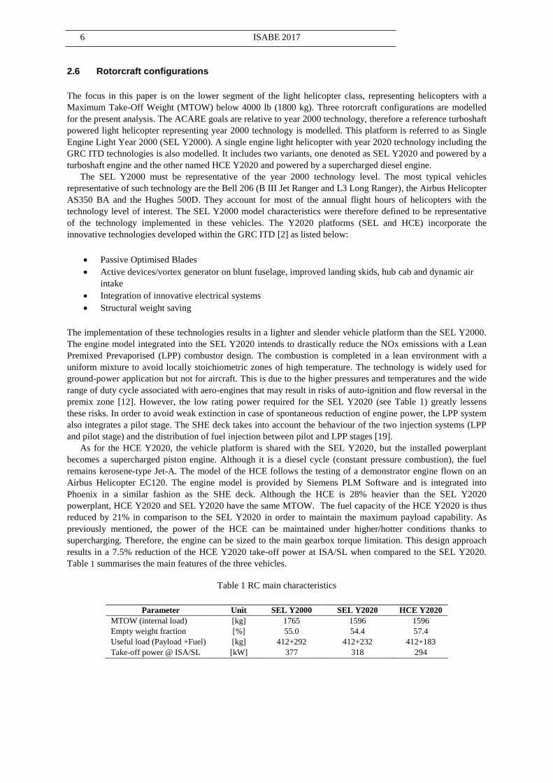
Table 1 summarises the main features of the three vehicles.
Table 1 RC main characteristics
Parameter Unit SEL Y2000 SEL Y2020 HCE Y2020
MTOW (internal load) [kg] 1765 1596 1596
Empty weight fraction [%] 55.0 54.4 57.4
Useful load (Payload +Fuel) [kg] 412+292 412+232 412+183
Take-off power @ ISA/SL [kW] 377 318 294

ENCONNIERE ET AL. MANUSCRIPT NUMBER 7
3.0 RESULTS
In this section, the payload-range capabilities of the three light helicopters are first compared in order to
appreciate the merits and drawbacks of the Clean Sky helicopter concepts. Then, in order to complete the
analysis, the environmental impact of each rotorcraft is analytically assessed at mission level. CO2 and NOx
emissions are evaluated and statistically compared.
3.1 Payload-Range comparison
The Payload-Range (PR) diagrams built for the three helicopters are defined by three points: maximum useful
load (A), maximum range at maximum payload (B), and maximum range without payload (C). The point A is
directly taken from the useful load of each vehicle given in
Table 1. Points B and C require the definition of a mission procedure for each vehicle in order to establish the
maximum range reachable with their respective fuel allowance. Thus, every mission is run following the same
routine for take-off, climb, descent and landing. These segments are defined by GRC5. The mission is a single
leg with a cruise altitude of 2500 ft. The reserve is defined as the fuel needed to realise a 60kts loiter for 20
minutes at 2000 ft. The cruise speed is set as the best range speed (Vr), defined as the speed that minimises the
ratio engine fuel flow over airspeed and so, maximises the range attainable. Max Range point and Vr are
graphically defined in Figure 4.
Figure 4 Definition of the best range speed
The engine fuel flows of the three vehicles are plotted versus airspeed for AUM equals MTOW and Empty
Weight (EW) in Figure 5. It is observed that Vr tends to decrease with a reduction of the AUM. However, the
effect of the AUM on Vr differs for each helicopter platform; whilst AUM has a relatively low effect for the SEL
Y2020, it has a large impact for the HCE Y2020. Note also that the SEL Y2020 has the highest V r out of the
three vehicles. The missions simulated to generate the PR were run at constant cruise speed. This speed was
defined as the Vr for the average AUM during the cruise segment. Once the maximum range is mathematically
evaluated, a mission file is created to be run by PhoeniX. An iterative process over the mission range follows to
adjust the maximum range evaluation to take into account all the mission segments and the gradual weight
reduction of the vehicle. The same method is employed for the three vehicles.
Figure 5 Engine fuel flow vs airspeed for the three helicopters

8 ISABE 2017
The SEL Y2020 was flown at the same speed for the two points of the diagram: B and C. The best range speed
of the SEL Y2020 was 7% and 19% faster than the average Vr of the SEL Y2000 and the HCE Y2020,
respectively. 3% and 10% differences were found between the Vr at maximum payload and no payload of the
SEL Y2000 and the HCE Y2020, respectively. Finally, the PR diagrams of the three vehicles are shown in
Figure 6.
Figure 6 Lightweight helicopters Payload-Range comparison
The PR diagrams of the two turboshaft-powered vehicles are similar. This highlights the method deployed in the
design of the SEL Y2020 where the benefits of the GRC ITD technologies were translated into reduced fuel
consumption rather than increased performance. It results in a 20% reduction of the fuel capacity of SEL Y2020
compared to the SEL Y2000. Due to its higher empty weight, the HCE Y2020 has a theoretical 15% and 14%
reduction in useful load compared to SEL Y2000 and SEL Y2020, respectively. However, the diesel engine
powered helicopter presents greater ranges than the turboshaft-powered vehicles and depending on the real use
of the helicopter, the payload penalty may never be seen. A 73% and 83% increase in range was found for
points B and C, respectively, compared with the turboshaft powered SEL.
3.2 Mission analysis
As previously mentioned, the environmental impact assessment is carried out at mission level over three distinct
missions representative of typical lightweight helicopter applications: passenger transport, police/law
enforcement, and training. The profiles of these missions were designed following European Helicopter
Operator Committee (EHOC) and Clean Sky partners’ advice with regard to flight procedures. As shown in
Figures 7-8, the passenger mission is a succession of four pick-up & drop-off segments. The helicopter takes off
from the helipad to pick-up the designated passenger(s) from a secondary location and transfers them to a drop-
off point. This procedure is repeated four times before the vehicle returns to the initial helipad. The hypothetical
law enforcement scenario in Figures 9-10 represents a high altitude surveillance role over five adjacent areas.
The scenario of the training mission is a combination of hover, climb, and level flight at various speeds and
altitudes as illustrated in Figures 11-12. The different scenarios considered in the mission analysis cover the
range of roles light helicopters perform.
Figure 7 Passenger mission altitude and airspeed
profiles
Figure 8 Passenger mission trajectory

ENCONNIERE ET AL. MANUSCRIPT NUMBER 9
Figure 9 Police mission altitude and airspeed profiles
Figure 10 Police mission geographical trajectory
Figure 11 Training mission altitude and airspeed profiles
Figure 12 Training mission geographical trajectory
The overall emissions results for each helicopter platform are summarised in Table 2 to Table 4, where CO2 and
NOx emissions are compared and then statistically analysed. The NOx rate emission vs Power are also evaluated
at SL/ISA conditions. The delta in CO2 emissions between the turboshaft-powered helicopters is consistent over
the three scenarios, with 20% reduction achieved by the SEL Y2020 compared with the SEL Y2000. This is not
the case for the NOx emissions, where the standard deviation is high (14%). An average 49% reduction in NOx
emission is achieved by SEL Y2020. With regards to the HCE Y2020 gaseous emissions, CO2 and NOx
emissions are 63% lower than the SEL Y2000 ones. The HCE Y2020 CO2 emissions are on average 53% lower
than the SEL Y2020. The NOx emissions are once again largely dependent on the mission scenario with a
standard deviation of 18%. On average, the HCE Y2020 emits 23% less NOx than the SEL Y2020 counterpart.
Table 2 CO2 and NOx emissions comparison at Passenger mission
Passenger
SEL Y2020 vs
SEL Y2000
[%Δ]
HCE Y2020 vs
SEL Y2000
[%Δ]
HCE Y2020 vs
SEL Y2020
[%Δ]
CO2 [kg] -21.5 -60.5 -49.8
NOx [kg] -61.7 -65.3 -9.3
Table 3 CO2 and NOx emissions comparison at Police mission
Police
SEL Y2020 vs
SEL Y2000
[%Δ]
HCE Y2020 vs
SEL Y2000
[%Δ]
HCE Y2020 vs
SEL Y2020
[%Δ]
CO2 [kg] -18.5 -63.5 -55.3
NOX [kg] -33.9 -62.6 -43.5

10 ISABE 2017
Table 4 CO2 and NOx emissions comparison at Training mission
Training
SEL Y2020 vs
SEL Y2000
%Δ
HCE Y2020 vs
SEL Y2000
%Δ
HCE Y2020 vs
SEL Y2020
%Δ
CO2 [kg] -18.0 -64.0 -56.1
NOX [kg] -52.1 -61.1 -18.8
Figure 13 and Figure 14 show the CO2 and NOx production rates respectively for the police scenario. As
expected, the HCE Y2020 presents the minimum CO2 production rate in all the flight segments. The regions
observed with higher CO2 emission rates correspond to the flight legs where the helicopter transits between
surveillance areas at high speed and altitude. As for the NOx emissions, the HCE Y2020 produces clearly less
NOx at low power settings. However, during the transition segments, the SEL Y2020 NOx production rates are
lower than during the surveillance segments. NOx emissions of the Y2020 vehicles cannot be put apart in the
transition segments.
Figure 13 CO2 production rate comparison at Police
mission Figure 14 NOx production rate comparison at Police
mission
Figure 15 represents the NOx production rate of each vehicle over the first leg of the passenger mission. It shows
that the SEL Y2020 presents a lower NOx production rate than the HCE Y2020 at cruise but the opposite is
observed on the idle, take-off, and landing segments. Therefore, as 9 take-off and landing manoeuvres are
performed during the passenger mission, the production rates at take-off and landing prevail over the cruise ones
and, as a result, the NOx emissions for the SELY2020 are 9.3% higher compared to the HCE Y2020 at mission
level. It demonstrates the dominant impact of the take-off and landing segments on the NOx emissions. The
engines NOx production rates versus shaft power are plotted in Figure 16 to explain the aforementioned result.
In this graph, it is noticeable that, whilst SEL Y2000 and HCE Y2020 NOx rates are essentially proportional to
shaft power, the SEL Y2020 NOx production oscillates. These fluctuations are a direct cause of the presence of a
pilot stage along the LPP ones (for low power rating) and the gradual distribution of the airflow to a number of
stages when the power rating increases. The SEL Y2020 combustor is, therefore, more effective at certain power
settings from the NOx production rate point of view. In particular, it is observed that for certain range of engine
shaft power, the NOx rate of the HCE Y2020 is higher than the SEL Y2020 one. This fact explains that at cruise
conditions, where the engine power demand is relatively high, the HCE Y2020 produces more NOx than the
SEL Y2020 operating at same conditions.

ENCONNIERE ET AL. MANUSCRIPT NUMBER 11
Figure 15 NOx production rate comparison at passenger
mission 1st leg
Figure 16 NOx production rate vs. Power at ISA/SL
4.0 CONCLUSIONS
An analytical method was presented to assess the benefits linked with the integration of the GRC ITD
technologies in terms of rotorcraft performance and environmental impact. This methodology was employed to
evaluate the environmental benefits of the integration of advanced powerplant into light helicopters. Three
vehicles were modelled: a turboshaft engine powered configuration with year 2000 technology, a conceptual
configuration corresponding to a turboshaft-engine-powered vehicle with projected technologies up until the
year 2020 with Clean Sky benefits, and a supercharged diesel cycle engine powered helicopter derivate from the
conceptual SEL.
The PR diagrams of the two turboshaft-powered helicopters demonstrate the method followed to design and
integrate the Clean Sky technologies into the SEL Y2020 model, as the performances of these two vehicles are
similar. As previously mentioned, the HCE Y2020 platform is based on the SEL Y2020 one, adapted to
integrate the diesel engine. It signifies an increase in vehicle empty weight at a cost of a lower fuel available in
order to maintain the MTOW. Despite the lower fuel available, the HCE Y2020 demonstrates a maximum range
83% greater than the turboshaft-powered models.
The gaseous emissions of the vehicles were evaluated over three scenarios representative of the activities of
light helicopters. On these missions, the HCE Y2020 surpasses the goals set by GRC, achieving over 60%
reduction in both NOx and CO2 emissions when compared to the SEL Y2000. The SEL Y2020, on the other
side, just reaches the designated goals with emissions cut by 19% and 49% for CO2 and NOx, respectively, when
compared to SEL Y2000. However, the SEL Y2020 performs greater over shorter scenarios when compared to
SEL Y2000 as seen in reference [20]. The direct effect of the LPP technology implemented in the SEL Y2020
was also discussed. The NOx production rate is fluctuating with the engine shaft power, resulting in regions
where the LPP turboshaft emits less NOx than the HCE. Finally, the direct comparison between SEL Y2020 and
HCE Y2020 highlighted the superior performance of HCE engine over the conventional gas turbine for the
simulated missions.
ACKNOWLEDGMENTS The authors would like to thank all the GRC leaders/participants for their valuable contributions as well as the
Clean Sky JTI for funding this research activity. Special thanks to Safran Helicopter Engines for their helpful
comments.
REFERENCES
[1] “Air Transport Action (ATAG),” [Online]. Available: http://atag.org. [Accessed June 2016].
[2] “Clean Sky innovation takes off,” Clean Sky, [Online]. Available: http://cleansky.eu. [Accessed June
2016].
[3] Royal Comission on Environmental Pollution, [Online]. Available: http://www.rcep.org/uk/reports/sr-
2002-aircraft/documents/aivation-report.pdf. [Accessed June 2016].

12 ISABE 2017
[4] J. Clarke, “The role of advanced air traffic management in reducing the impact of aircraft noise and
enabling aviation growth,” Journal of Air Transport Management, vol. 9, no. 3, pp. 161-165, 2003.
[5] European Commission, “Flightpath 2050 Europe's Vision for Aviation,” 2011. [Online]. Available:
ec.europa.eu/transport/sites/transport/files/modes/air/doc/flightpath2050.pdf. [Accessed November 2016].
[6] K. M. Rosen, “A Prospective: The Importance of Propulsion Technology to the Development of Helicopter
Systems With a Vision for the Future The 27th Alexander A. Nikolsky Lecture,” Journal of American
Helicopter Society, vol. 53, no. 4, pp. 307-337, 2008.
[7] J. Castor, J. Martin, and C Bradley, “Coumpound Cycle Engine for Helicopter Application,” NASA,
NAS3-24346, 1987.
[8] C. F. McDonald, A. F. Massardo, C. Rodgers, A. Stone, “Recuperated gas turbine aeroengines. Part III:
engine concepts for reduced emissions, lower fuel consumption, and noise abatement,” Aircraft
Engineering and Aerospace Technology, vol. 80, no. 4, pp. 408-426, 2008.
[9] F. Ali, K. Tzanidakis, I. Goulos, V. Pachidis, R. d'Ippolito, “Multi-Objectie Optimization of Conceptual
Rotorcraft Powerplants: Trade-Off Between Rotorcraft Efficiency and Environmental Impact,” Journal of
Engineering for Gas Turbines and Power , vol. 137, no. 7, p. 071201, 2015.
[10] Q. Li, W. Fan, “Parametric Cycle Analysis of Dual-Spool Mixed-Exhaust Turbofan with Interstage Turbine
Burner,” 45th AIAA Aerospace Sciences Meeting and Exhibit, Reno, Nevada, January 2007.
[11] D. R. Lefebvre, & A. H. Ballal , “Polutants Reduction by Control of Flame Temperature,” in Gas Turbine
Combustion- Alternative Fuels and Emissions, CRC press, 2010, pp. 391-428.
[12] R. Tacina, C. Wey, P. Laing, A. Mansour, “A Low NOx Lean-Direct Injection, Multi Integrated Module
Combustor Concept for Advanced Aircraft Gas Turbines - NASA/TM-2002-211347,” Conference on
Technologies and Combustion for a Clean Environment, 2001.
[13] I. Goulos, V. Pachidis, R. d’Ippolito, J. Stevens, and C. Smith, “An Integrated Approach for the
Multidisciplinary Design of Optimum Rotorcraft Operation,” Journal of Engineering for Gas Turbines and
Power, vol. 134, no. 9, pp. 091701-091701-10, 2012.
[14] “NOESIS-OPTIMUS, the Industry-Leading PIDO Software Platform,” Noesis Solution, [Online].
Available: http://www.noesissolutions.com/our-products/optimus. [Accessed June 2016].
[15] C. Serr, J. Hamm, F. Toulmay, G. Polz, H.J. Langer, M. Simoni, M. Bonetti, A. Russo, C. Young, J.
Stevens, A. Desopper, D Papillier, “Improved Methodology for Take-Off and Landing Operational
Procedures, the RESPECT programme,” in 25th European Rotorcraft Forum, Rome, 1999.
[16] C. Serr, G. Polz, J. Hamm, J. Hughes, M. Simoni, A. Ragazzi, A. Desopper, A. Taghizad, H. Langer, C.
Young, A. Russo, A. Vozella and J. Stevens, “ Rotorcraft Efficient and Safe Procedures for Critical
Trajectories,” Air Space Eur., vol. 3, no. 3, pp. 266-270, 2001.
[17] FRIENDCOPER consortium, “Final Report - FRIENDCOPTER (Integration of technologies in support of
a passenger and environmentally friendly helicopter),” 2009.
[18] M. Gervais, V. Gareton, A. Dummel, R. Heger, “Validation of EC130 and EC135 Environmental Impact
Assessment using HELENA,” in American Helicopter Society 66th Annual Forum, Phoenix, 2010.
[19] C. Smith, V. Pachidis, A. Castillo Pardo, E. Gires, J. Stevens, L. Thevenot, R. d'Ippolito, “Achieving
Rotorcraft Noise and Emissions Reduction for "Clean Sky" - The Measurement of Success,” Challenges in
European Aerospace, 5th CEAS Air & Space Conference, 2015.
[20] J. Ortiz-Carretero, J. Enconniere, V. Pachidis, J. Stevens, C. Smith, L. Thevenot, and R. Ippolito, “Clean
Sky Technology Evaluator Green Rotorcraft Mission Environmental Performance Analysis,” in AEGATS
2016, Paris, 2016.


![2014 ram 2500/3500 · 2014. 2. 28. · New 2014 Ram 3500 Heavy Duty: B est combination of torque, towing, payload and load-levelling capability. [2] max payload 3,320 kg (7,320 lb)](https://img.pdfslide.net/doc/110x75/5fc8c3803741807a3a7a5411/2014-ram-25003500-2014-2-28-new-2014-ram-3500-heavy-duty-b-est-combination.jpg)