Embed Size (px)
Citation preview
The Impact of
Higher Data Rate
Requirements on MIPI CSI℠ and MIPI
DSI℠ Designs
Brian Daellenbach - Northwest Logic
Ashraf Takla - Mixel
Overview
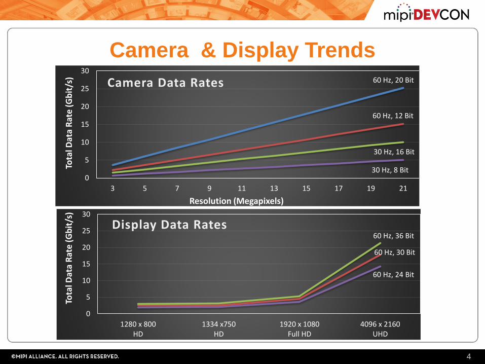
• The trend towards higher resolution, pixel depth and
frame rate cameras and displays is driving the need for
higher data rate interfaces.
• The MIPI Alliance Camera Serial Interface (CSI) and
Display Serial Interface (DSI) standards are evolving to
meet these needs.
• This presentation provides an overview of these trends,
the evolving standards, and the corresponding impact
on CSI and DSI designs.
2
Speaker Introduction
• Brian Daellenbach
• President of Northwest Logic
• Located in Beaverton, Oregon
• Controller IP Provider – MIPI, PCIe, DDR/HBM
• Ashraf Takla
• President of Mixel
• Located in San Jose, California
• MIPI PHY Provider – D-PHY, C-PHY, M-PHY
• Together Northwest Logic and Mixel provide a complete, silicon-
proven, high-performance, low-power MIPI solution
3
60 Hz, 30 Bit
60 Hz, 36 Bit
0
5
10
15
20
25
30
1280 x 800HD
1334 x750HD
1920 x 1080Full HD
4096 x 2160UHD
Tota
l Dat
a R
ate
(G
bit
/s)
Display Data Rates
Camera & Display Trends
4
60 Hz, 20 Bit
60 Hz, 12 Bit
30 Hz, 16 Bit
30 Hz, 8 Bit0
5
10
15
20
25
30
3 5 7 9 11 13 15 17 19 21
Tota
l Dat
a R
ate
(G
bit
/s)
Camera Data Rates
Resolution (Megapixels)
60 Hz, 24 Bit
MIPI Standards Background
• MIPI Alliance was formed in 2003 to “to benefit the mobile
industry by establishing specifications for standard hardware
and software interfaces in mobile devices”
• Camera Serial Interface (CSI)
• Provides a packet-based protocol for interfacing to mobile cameras
• Widely used
• Display Serial Interface (DSI)
• Provides a packet-based protocol for interfacing to mobile displays
• Widely used
• Widespread adoption of these standards in the high-volume
mobile market has resulted in low-cost cameras and
displays which are being used in other markets also
5
MIPI PHY Standards
• D-PHY• N data lanes and 1 clock lane (2 pins per lane)
• Source synchronous (clock provided separately from the data)
• Typically 1-4 data lanes are used. 8 infrequently used.
• Switches between Low Power (LP) and High Speed (HS) modes• LP: LVCMOS, HS: Sub-LVDS
• Widely used in the Camera and Display markets
• C-PHY• N data lanes (3 pins per lane – also known as trios)
• Uses 3 phase symbol encoding (2.28 bits/symbol).
• Clock embedded in each data lane.
• Typically 1-3 lanes are used to be pin count compatible with D-PHY. More lanes may be used in the future.
• LP and HS modes
• Starting to be used in the Camera market
• M-PHY• SERDES-based standard
• Not being adopted in the Camera and Display markets yet due to higher cost
6
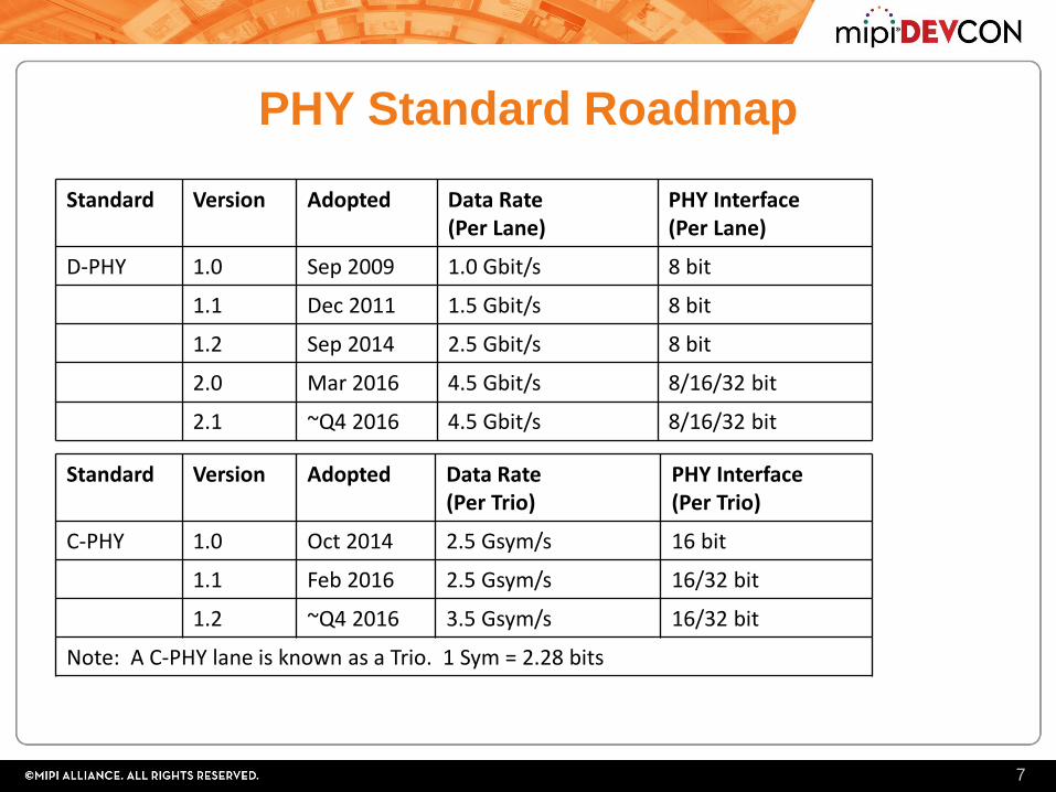
PHY Standard Roadmap
7
Standard Version Adopted Data Rate(Per Lane)
PHY Interface(Per Lane)
D-PHY 1.0 Sep 2009 1.0 Gbit/s 8 bit
1.1 Dec 2011 1.5 Gbit/s 8 bit
1.2 Sep 2014 2.5 Gbit/s 8 bit
2.0 Mar 2016 4.5 Gbit/s 8/16/32 bit
2.1 ~Q4 2016 4.5 Gbit/s 8/16/32 bit
Standard Version Adopted Data Rate(Per Trio)
PHY Interface(Per Trio)
C-PHY 1.0 Oct 2014 2.5 Gsym/s 16 bit
1.1 Feb 2016 2.5 Gsym/s 16/32 bit
1.2 ~Q4 2016 3.5 Gsym/s 16/32 bit
Note: A C-PHY lane is known as a Trio. 1 Sym = 2.28 bits
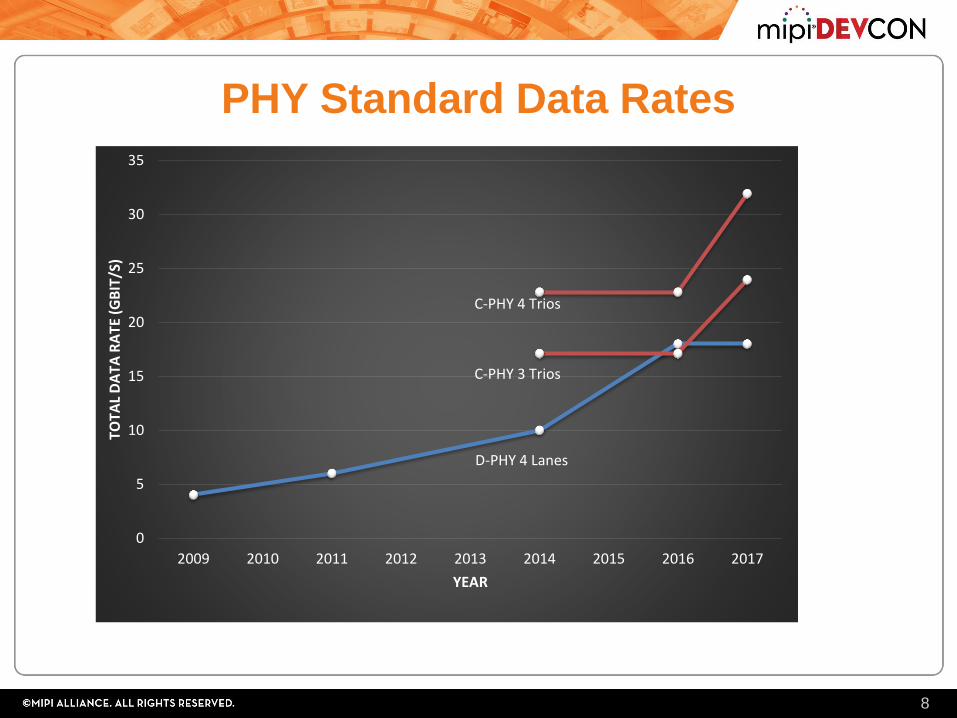
PHY Standard Data Rates
8
0
1
2
3
4
5
6
7
8
9
10
2009 2010 2011 2012 2013 2014 2015 2016 2017 2018
Chart Title
D-PHY C-PHY
D-PHY 4 Lanes
C-PHY 3 Trios
C-PHY 4 Trios
0
5
10
15
20
25
30
35
2009 2010 2011 2012 2013 2014 2015 2016 2017
TOTA
L D
ATA
RA
TE (
GB
IT/S
)
YEAR
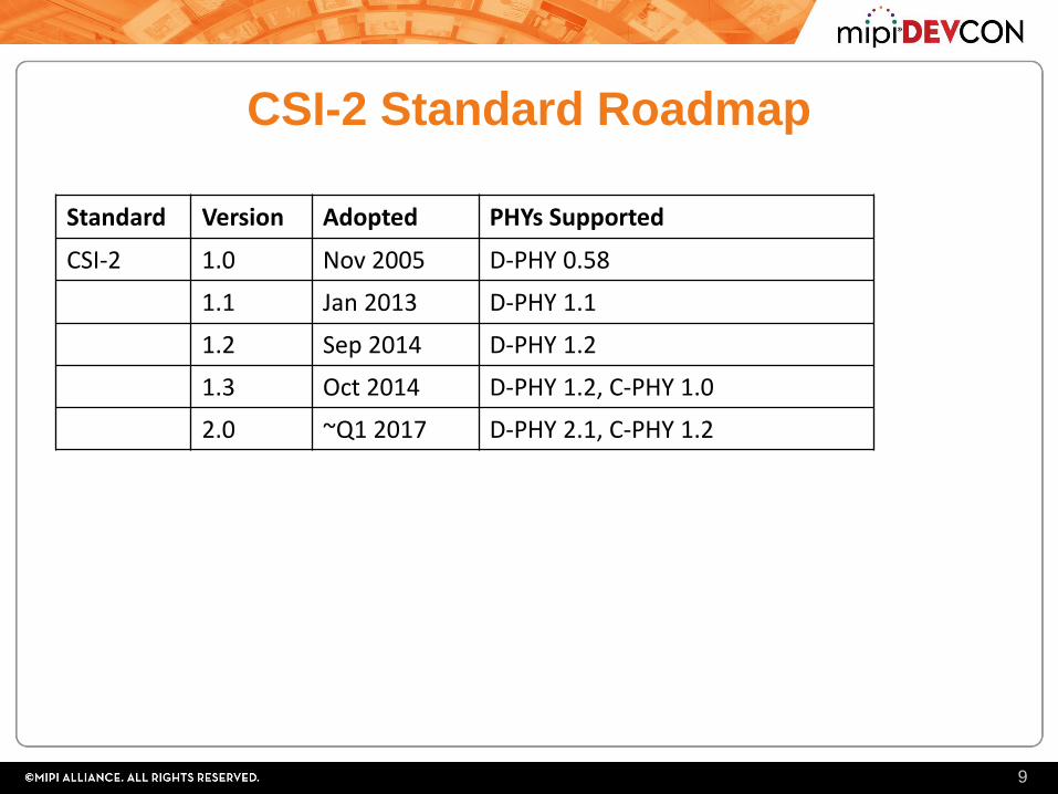
CSI-2 Standard Roadmap
9
Standard Version Adopted PHYs Supported
CSI-2 1.0 Nov 2005 D-PHY 0.58
1.1 Jan 2013 D-PHY 1.1
1.2 Sep 2014 D-PHY 1.2
1.3 Oct 2014 D-PHY 1.2, C-PHY 1.0
2.0 ~Q1 2017 D-PHY 2.1, C-PHY 1.2
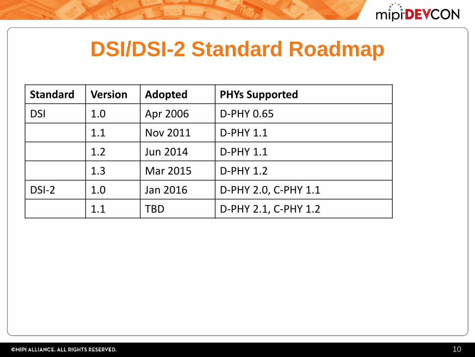
DSI/DSI-2 Standard Roadmap
10
Standard Version Adopted PHYs Supported
DSI 1.0 Apr 2006 D-PHY 0.65
1.1 Nov 2011 D-PHY 1.1
1.2 Jun 2014 D-PHY 1.1
1.3 Mar 2015 D-PHY 1.2
DSI-2 1.0 Jan 2016 D-PHY 2.0, C-PHY 1.1
1.1 TBD D-PHY 2.1, C-PHY 1.2
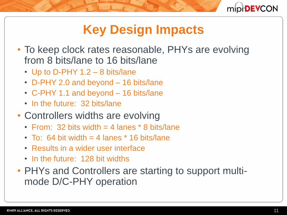
Key Design Impacts
• To keep clock rates reasonable, PHYs are evolving from 8 bits/lane to 16 bits/lane• Up to D-PHY 1.2 – 8 bits/lane
• D-PHY 2.0 and beyond – 16 bits/lane
• C-PHY 1.1 and beyond – 16 bits/lane
• In the future: 32 bits/lane
• Controllers widths are evolving• From: 32 bits width = 4 lanes * 8 bits/lane
• To: 64 bit width = 4 lanes * 16 bits/lane
• Results in a wider user interface
• In the future: 128 bit widths
• PHYs and Controllers are starting to support multi-mode D/C-PHY operation
11
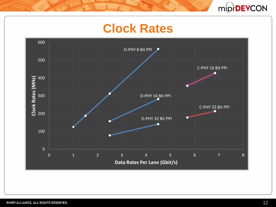
Clock Rates
12
D-PHY 8 Bit PPI
D-PHY 16 Bit PPI
D-PHY 32 Bit PPI
C-PHY 16 Bit PPI
C-PHY 32 Bit PPI
0
100
200
300
400
500
600
0 1 2 3 4 5 6 7 8
Clo
ck R
ate
s (M
Hz)
Data Rates Per Lane (Gbit/s)
Mixel PHYs
• Tracking the standards with several generations of
silicon-proven D-PHYs
• 1.0 Gbps -> 1.5 Gbps -> 2.5 Gbps -> D+C-PHY support
• Support range of PHY configurations
• D-PHY only, D/C-PHY, C-PHY only, M-PHY
• Broad process support
• 180nm down to 16nm
• Broad foundry support
• 7 different foundries including TSMC, UMC, GF, SMIC, and others
• Full featured & differentiated solution
• Low power, small area, high performance, mature, silicon proven
13
Northwest Logic Controllers
• First Generation
• CSI-2 and DSI Controller Cores are 32 bits wide
• Second Generation
• CSI-2 and DSI-2 Controller Cores support both 32 and 64 bit width
• 32 bit: minimize size and power for lower data rates
• 64 bit: minimize clock rate for high data rates
• Full featured, high-performance, low power, easy to
use
• Delivered as a complete solution integrated and verified
with the Mixel PHY
14
Conclusion
• The trend towards higher resolution, pixel depth and
frame rate cameras and displays is driving the need for
higher data rate interfaces.
• The MIPI Alliance Camera Serial Interface (CSI) and
Display Serial Interface (DSI) standards are evolving to
meet these needs.
• These trends will impact MIPI designs in several ways:
• Higher I/O and clock rates, wider interfaces, use of multi-mode
PHYs, use of data compression, etc.
• MIPI designers should consider these trends as they
create their product roadmaps and associated designs.
15
For More Information
• Visit our exhibit in the Grand Hall during the
conference.
• Contact Northwest Logic at:
• Brian Daellenbach
• www.nwlogic.com
• Contact Mixel at:
• Ashraf Takla
• www.mixel.com
16
![MIPI CSI-2 Video Output Board [SVO-03-MIPI] Hardware ... · SVO-03-MIPI Hardware Specification 1.0 1 1. Outline This document is a hardware specification of the board "SVO-03-MIPI"](https://img.pdfslide.net/doc/110x75/5f0b75457e708231d4309ddc/mipi-csi-2-video-output-board-svo-03-mipi-hardware-svo-03-mipi-hardware-specification.jpg)