Embed Size (px)
Citation preview

iv
SCHOOL OF SCIENCE AND ENGINEERING
THE IMPROVEMENT OF A DOUBLE GLAZING STORAGE
SOLAR WATER HEATER
Capstone Design
Spring 2015
By: Mariyem Touzalt
Supervisor: Dr. Darhmaoui Hassane

v
To the memory of my beloved Father May God bless his soul,
My Mother and
My brother…

vi
vii
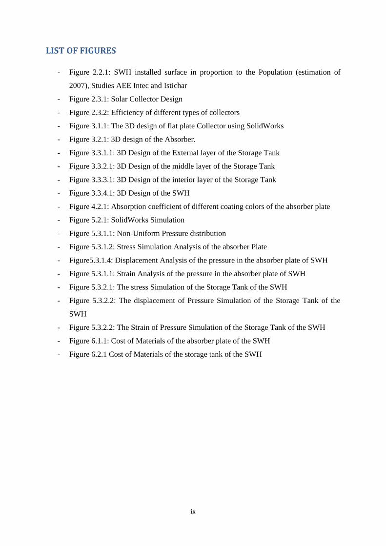
Table of Contents
LIST OF FIGURES ................................................................................................................................................ ix
LIST OF TABLES ................................................................................................................................................... x
ABSTRACT ........................................................................................................................................................... xi
RESUME .............................................................................................................................................................. xii
GLOSSARY ......................................................................................................................................................... xiii
1. INTRODUCTION ............................................................................................................................................ 1
1.1 CONTEXT ..................................................................................................................................................... 1
1.2 PREVIOUS WORK ....................................................................................................................................... 1
1.3 PROJECT OBJECTIVES .............................................................................................................................. 1
1.4 STEEPLE ANALYSIS .................................................................................................................................. 2
2. LITERATURE REVIEW ................................................................................................................................. 4
2.1 HISTORY OF SOLAR HEATING IN THE WORLD .................................................................................. 4
2.2 SOLAR WATER HEATERS IN MOROCCO .............................................................................................. 4
2.3 GENERAL DESIGN OF SOLAR WATER HEATERS ........................................................................ 6
2.4 SOLAR WATER HEATERS WITH INTEGRATED TANK ....................................................................... 8
3. THE DOUBLE GLAZING BUILT-IN STORAGE WATER SYSTEM DESIGN ....................................... 10
3.1 COLLECTOR OF THE DOUBLE GLAZING STORAGE WATER HEATER SYSTEM ........................ 10
3.2 ABSORBER OF THE DOUBLE GLAZING BUILT-IN SOLAR WATER SYSTEM .............................. 11
3.3 STORAGE TANK OF THE DOUBLE GLAZING BUILT-IN SOLAR WATER SYSTEM ..................... 13
3.3.1 EXTERNAL LAYER OS THE STORAGE TANK OF THE SWH ..................................................... 13
3.3.2 MIDDLE LAYER OS THE STORAGE TANK OF THE SWH .......................................................... 14
3.3.3 INTERNAL LAYER OS THE STORAGE TANK OF THE SWH ...................................................... 15
3.3.4 DESIGN OF SWH SYSTEM ................................................................................................................ 17
4. THE DOUBLE GLAZING BUILT-IN STORAGE WATER SYSTEM MATERIALS: MECHANICAL
PROPERTIES ........................................................................................................................................................ 18
4.1 DEFINITIONS: ............................................................................................................................................ 18
4.2 PROPERTIES OF POTENTIAL MATERIALS FOR THE ABSROBER PLATE ..................................... 19
4.3 PROPERTIES OF POTENTIAL MATERIALS FOR THE STORAGE TANK ......................................... 21
5. SOLIDWORKS SIMULATION OF THE DOUBLE GLAZING BUILT-IN STORAGE WATER SYSTEM
22
5.1 SOLIDWORKS COMPUTER-AIDED DESIGN ........................................................................................ 22
5.2 SOLIDWORKS SIMULATION .................................................................................................................. 22
.5.3 SIMULATION ANALYSIS OF THE DOUBLE GLAZING BUILT-IN STORAGE WATER SYSTEM:
............................................................................................................................................................................ 24
5.3.1 SIMULATION ANALYSIS OF THE ABSORBER PLATE ............................................................... 24
5.3.2 SIMULATION ANALYSIS OF THE INTERIOR LAYER OF THE STORAGE TANK ................... 30
6. ECONOMIC ANALYSIS OF THE DOUBLE GLAZING SOLAR WATER HEATER .............................. 36
6.1 COSTS ANALYSIS OF THE POTENTIAL MATERIALS OF THE ABSORBER PLATE OF THE SWH
............................................................................................................................................................................ 36
6.2 COSTS ANALYSIS OF THE POTENTIAL MATERIALS OF THE STORAGE TANK OF THE SWH . 37
6.3 CONCLUSION AND DISCUSSION .......................................................................................................... 38

viii
7. CONCLUSION .................................................................................................................................................. 39
BIBLIOGRAPHY .................................................................................................................................................. 40
APPENDIX A: SIMULATION MODEL CALCULATIONS .............................................................................. 42
ix
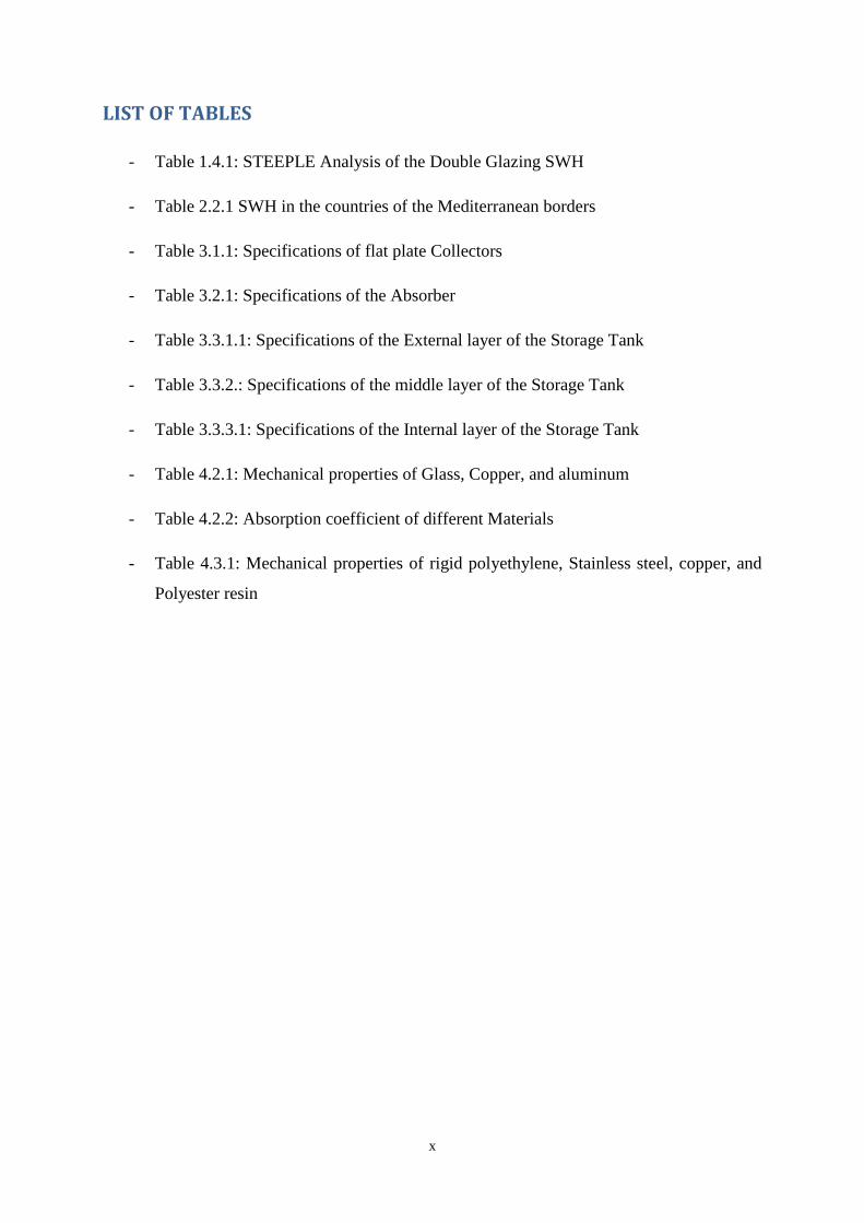
LIST OF FIGURES
- Figure 2.2.1: SWH installed surface in proportion to the Population (estimation of
2007), Studies AEE Intec and Istichar
- Figure 2.3.1: Solar Collector Design
- Figure 2.3.2: Efficiency of different types of collectors
- Figure 3.1.1: The 3D design of flat plate Collector using SolidWorks
- Figure 3.2.1: 3D design of the Absorber.
- Figure 3.3.1.1: 3D Design of the External layer of the Storage Tank
- Figure 3.3.2.1: 3D Design of the middle layer of the Storage Tank
- Figure 3.3.3.1: 3D Design of the interior layer of the Storage Tank
- Figure 3.3.4.1: 3D Design of the SWH
- Figure 4.2.1: Absorption coefficient of different coating colors of the absorber plate
- Figure 5.2.1: SolidWorks Simulation
- Figure 5.3.1.1: Non-Uniform Pressure distribution
- Figure 5.3.1.2: Stress Simulation Analysis of the absorber Plate
- Figure5.3.1.4: Displacement Analysis of the pressure in the absorber plate of SWH
- Figure 5.3.1.1: Strain Analysis of the pressure in the absorber plate of SWH
- Figure 5.3.2.1: The stress Simulation of the Storage Tank of the SWH
- Figure 5.3.2.2: The displacement of Pressure Simulation of the Storage Tank of the
SWH
- Figure 5.3.2.2: The Strain of Pressure Simulation of the Storage Tank of the SWH
- Figure 6.1.1: Cost of Materials of the absorber plate of the SWH
- Figure 6.2.1 Cost of Materials of the storage tank of the SWH
x
LIST OF TABLES
- Table 1.4.1: STEEPLE Analysis of the Double Glazing SWH
- Table 2.2.1 SWH in the countries of the Mediterranean borders
- Table 3.1.1: Specifications of flat plate Collectors
- Table 3.2.1: Specifications of the Absorber
- Table 3.3.1.1: Specifications of the External layer of the Storage Tank
- Table 3.3.2.: Specifications of the middle layer of the Storage Tank
- Table 3.3.3.1: Specifications of the Internal layer of the Storage Tank
- Table 4.2.1: Mechanical properties of Glass, Copper, and aluminum
- Table 4.2.2: Absorption coefficient of different Materials
- Table 4.3.1: Mechanical properties of rigid polyethylene, Stainless steel, copper, and
Polyester resin
xi
ABSTRACT
This capstone project study the performance of Double Glazing Built-in Storage water,
a system that consists of a solar water heater. Unlike the Thermosyphon systems, where the
collector panels and the storage tank are separated, Double Glazing Built-in Storage water
system has a storage tank integrated within the collector. The system proposed is composed of
an absorber plate where the upper surface will be the insulator and the lower surface will be in
direct contact with water.
This project will be an analysis of the properties of the Double Glazing Built-In-
Storage Solar Water system, the most important properties that will be discussed are
mechanical and thermal properties such as static, fatigue, drop tests, stress, yield strength,
young’s modulus, hardness, elongation to failure, strain, thermal conductivity, corrosion
resistance, oxidation resistance, and others. The mechanical properties of each part of the
system will be represented in a 3D design approach using solid modeling with a software
called “SolidWorks”, this software is used to optimize the performance and produce efficient
3D designs with accuracy and precision. The license of this software is available in the
university and it is legal and is ethical to use it.
This project has been done in three months, the first steps consist of finding the
different possible materials that could be used in the Double Glazing Built-in Storage water
system then study the mechanical and thermal properties of each part of the system using
SolidWorks that will give a clear idea of what the system looks like in a 3D perspective and
its performance.
xii
RESUME
Ce projet de fin d'étude a pour but d’évaluer, concevoir et analyser la performance du
système d'un chauffe-eau solaire à double vitrage avec réservoir intégré. Contrairement aux
systèmes thermosiphon, où les panneaux de collecteur et le réservoir de stockage sont séparés,
chauffe-eau solaire à double vitrage dispose d'un réservoir de stockage intégré dans le
collecteur.
Le système proposé est composé d'une plaque d'absorbeur où la surface supérieure sera
l'isolant et la surface inférieure seront en contact direct avec l'eau.
Ce projet sera une analyse des propriétés du chauffe-eau solaire à double vitrage, les
propriétés les plus importants qui seront abordés sont propriétés mécaniques et thermiques tels
que statique, fatigue, essais de chute, le stress, la limite d'élasticité, module d l’élasticité, la
dureté, allongement à la rupture, la déformation, la conductivité thermique, la résistance à la
corrosion, résistance à l'oxydation, et d'autres. Les propriétés mécaniques de chaque partie du
système seront représentés dans une approche de conception 3D utilisant la modélisation
solide avec un logiciel appelé "SolidWorks", ce logiciel est utilisé pour optimiser les
performances et de produire d’efficaces conceptions 3D avec exactitude et précision. La
licence de ce logiciel est disponible dans l'université et il est légal et éthique de l'utiliser.
Ce projet a été réalisé en trois mois, les premières étapes consistent à trouver les
différents matériaux qui pourraient être utilisés dans le système du chauffe-eau solaire à
double vitrage,, puis étudier les propriétés mécaniques et thermiques de chaque partie du
système en utilisant SolidWorks que va donner une idée claire de ce que le système ressemble
dans une perspective 3D et ses performances.

xiii
GLOSSARY
SWH Solar water heater
BIS Built-in Storage
CAD Computer-Aided Design
DCRE Development Centre of Renewable Energies
1
1. INTRODUCTION
1.1 CONTEXT
Despite the technology development, the question of energy is emerging as one of
our major concerns. Some of the sources are depleted, others pollute our environment. Our
needs are increasing every day, what should we use? We should lean toward renewable
energies that are almost inexhaustible like wind and sun. For solar energy, it is used for many
purposes like solar water heaters for home usage. This project will be a study of an innovative
double glazing solar water heater with an integrated tank. The main goal of this project is to
emphasize the performance of the system and simulate the behavior and mechanical
properties of solar water heater using the available and efficient materials.
1.2 PREVIOUS WORK
The present work is going to be a follow up on the work of a previous master Thesis of
student “Tarik Nabih”, in this thesis the student has focused on the design of the double
glazing solar water heater system and he used a tank with a volume of 120 liters. The work
done so far is a 3D design of the system and a flow simulation of the system using
“SolidWorks”, also some literature review on the different types of solar water heaters and
especially the one with an integrated tank with a rectangular shape. Additionally, the previous
study consists of comparing the theoretical results and experimental results done in
collaboration with the company IntellCap. The data found has been analyzed, and using the
software SolidWorks he found the 3D flow simulation of the double glazing solar water heater
system. But the student did not cover the mechanical and thermal properties of the system.
1.3 PROJECT OBJECTIVES
As previously mentioned, the general objective of this study is to evaluate the
mechanical performance, the thermal effectiveness, and the design of Double Glazing Built-in
Storage water system. In terms of thermal effectiveness and mechanical properties, the
specific objectives of the study are as follows:
2
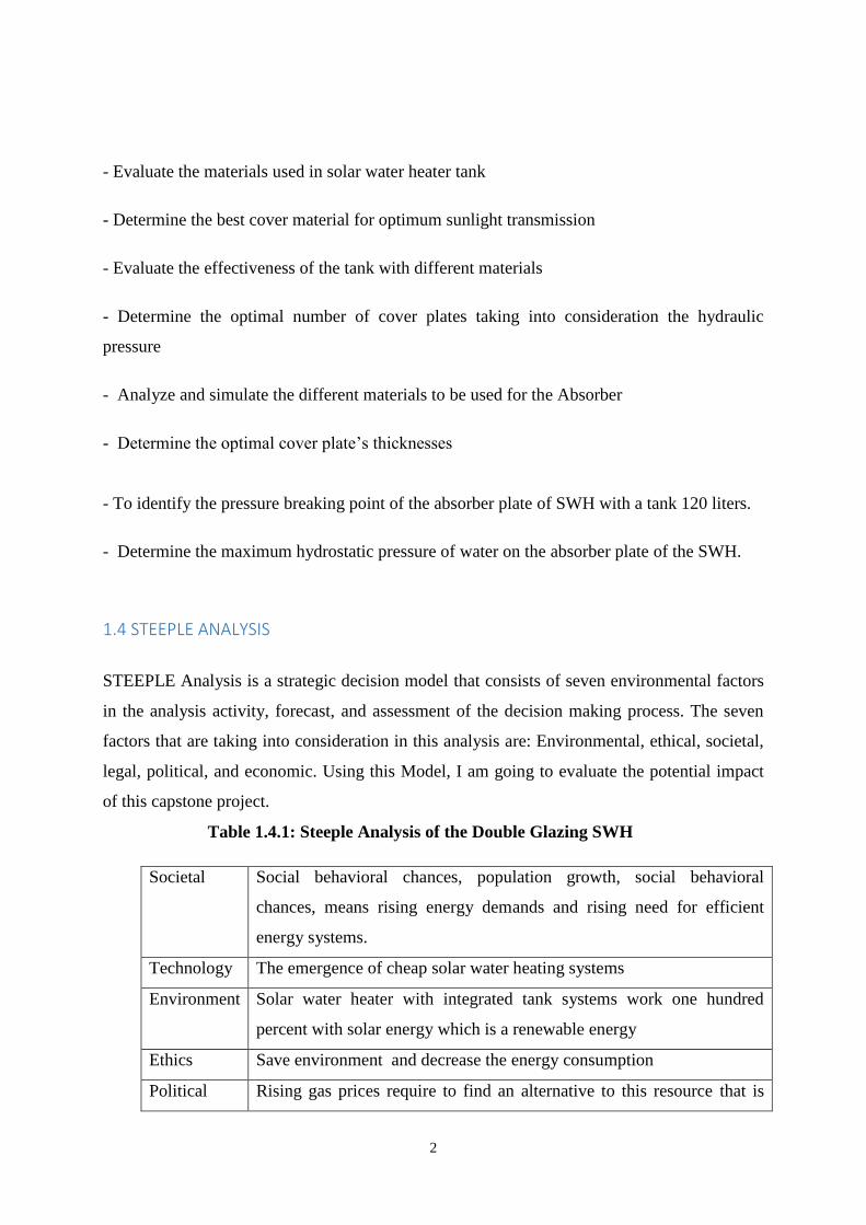
- Evaluate the materials used in solar water heater tank
- Determine the best cover material for optimum sunlight transmission
- Evaluate the effectiveness of the tank with different materials
- Determine the optimal number of cover plates taking into consideration the hydraulic
pressure
- Analyze and simulate the different materials to be used for the Absorber
- Determine the optimal cover plate’s thicknesses
- To identify the pressure breaking point of the absorber plate of SWH with a tank 120 liters.
- Determine the maximum hydrostatic pressure of water on the absorber plate of the SWH.
1.4 STEEPLE ANALYSIS
STEEPLE Analysis is a strategic decision model that consists of seven environmental factors
in the analysis activity, forecast, and assessment of the decision making process. The seven
factors that are taking into consideration in this analysis are: Environmental, ethical, societal,
legal, political, and economic. Using this Model, I am going to evaluate the potential impact
of this capstone project.
Table 1.4.1: Steeple Analysis of the Double Glazing SWH
Societal Social behavioral chances, population growth, social behavioral
chances, means rising energy demands and rising need for efficient
energy systems.
Technology The emergence of cheap solar water heating systems
Environment Solar water heater with integrated tank systems work one hundred
percent with solar energy which is a renewable energy
Ethics Save environment and decrease the energy consumption
Political Rising gas prices require to find an alternative to this resource that is

3
less costly
Legal Everybody has the right to use solar energy
Economic Solar water heating system enable less costly and more efficient and
reasonable energy consumption
4
2. LITERATURE REVIEW
2.1 HISTORY OF SOLAR HEATING IN THE WORLD
The use of solar energy (thermal and photovoltaic) started in several countries all over
the world: Australia, Canada, China, Germany, India, Israel, Japan, Portugal, Romania, Spain,
the United Kingdom and the United States.
The archives for solar collectors in the United States history are back to before 1900,
including a painted black tank mounted on a roof. In 1896, an American seal a tank in a
wooden box, creating "batch water heater" as they are called today. Although plate collectors
for solar water heating were used Florida and Southern California in the 1920s there was a
renewed interest in solar heating in North America after 1959, but especially after the 1974 oil
crisis [ 6 ].
According to what Jean Cariou said in his article titled “Solar Water Heater “, Solar
water heaters have become very popular in China, where basic models start at around 200
euros, much cheaper than in Western countries (about 80% less for a given size of the
collector). It is said that at least 30 million Chinese households now have a solar heating
system at home, and that popularity is due to the highly efficient evacuated tubes that allow
the heaters to operate even under gray skies and temperatures well below zero. [ 6 ]
2.2 SOLAR WATER HEATERS IN MOROCCO
In the late 70s, we witnessed the first solar water heaters installed in luxury residences,
knowing the prices were still very high and only some affluent of ecological fiber could afford
to buy them. Unfortunately, many of these facilities did not last long, due to poor quality of
solar water heaters imported and lack of qualified installers. This led to the end of the 90s, a
rejection and a lack of confidence to this type of product by the final consumer.
Because of all this wasted time, Morocco is ranked, within 8 square meters of solar collectors
per thousand capita, very bad ranking for the country among the other Mediterranean
countries including, in the list, Cyprus (788 m²/ 1 000 inhabitant.) and Greece (318 m²/ 1 000
inhabitant.) [ 14 ]. several industrial production of solar water heater was made in Morocco: in
most cases, they were doomed to failure.
5
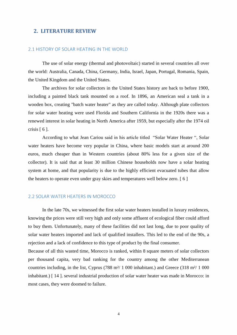
Table 2.2.1 SWH in the countries of the Mediterranean borders [ 14 ]
Figure 2.2.1: SWH Surface installed in proportion to the Population
(estimation of 2007), Studies AEE Intec and Istichar [ 14 ]
The Figure and table 2.2.1 show that morocco is still lagging behind in terms of renewable
energies especially in solar energy and this is mainly due to the weak demand and strong
competition from imported products (often in their country of origin, or were subsidized in
41%
31%
14%
6%
3%
1%
1% 1%
1%
1%
0% SWH Surface installed in proportion to the
population
China
Palestine /Israel
Greece
Turkey
Malta
Spain
France
Countries in the
Mediterranean borders
Number of m² of SWH Surface
per million habitant
China 651
Palestine /Israel 499
Greece 225
Turkey 94
Malta 50
Spain 19
France 16
Tunisia 15
Italy 12
Albania 11
Morocco 7
6
one way or another, which allows them to be now sold at very interesting prices). Although at
present, the days are gone when you had to prove to the purchaser that the solar water heater
is much more economical than electrical power, the commercialization of solar water heater is
still in dribs and drabs. This is caused by the high investment price (despite a return on
investment after 3 to 5 years), and the lack of pre-installations in buildings for public use.[ 14]
2.3 GENERAL DESIGN OF SOLAR WATER HEATERS
During the previous two centuries, different technologies and solar water heater models were
designed before converging the past 30 years towards homogenization systems [ 4 ]. The
principle of solar water heater is based in most cases on four main components:
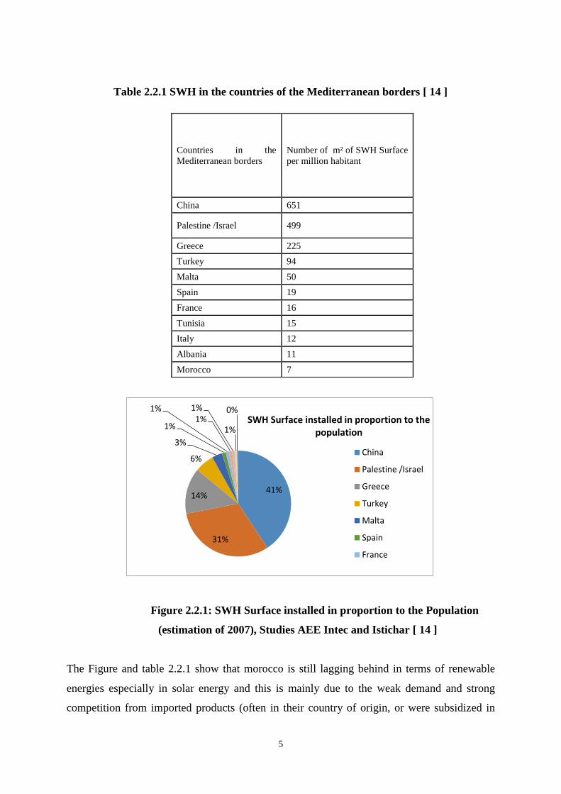
- The solar collector (flat collector or vacuum sensor) transforming solar energy into
thermal energy;
Figure 2.3.1: Solar Collector Design [ 5 ]
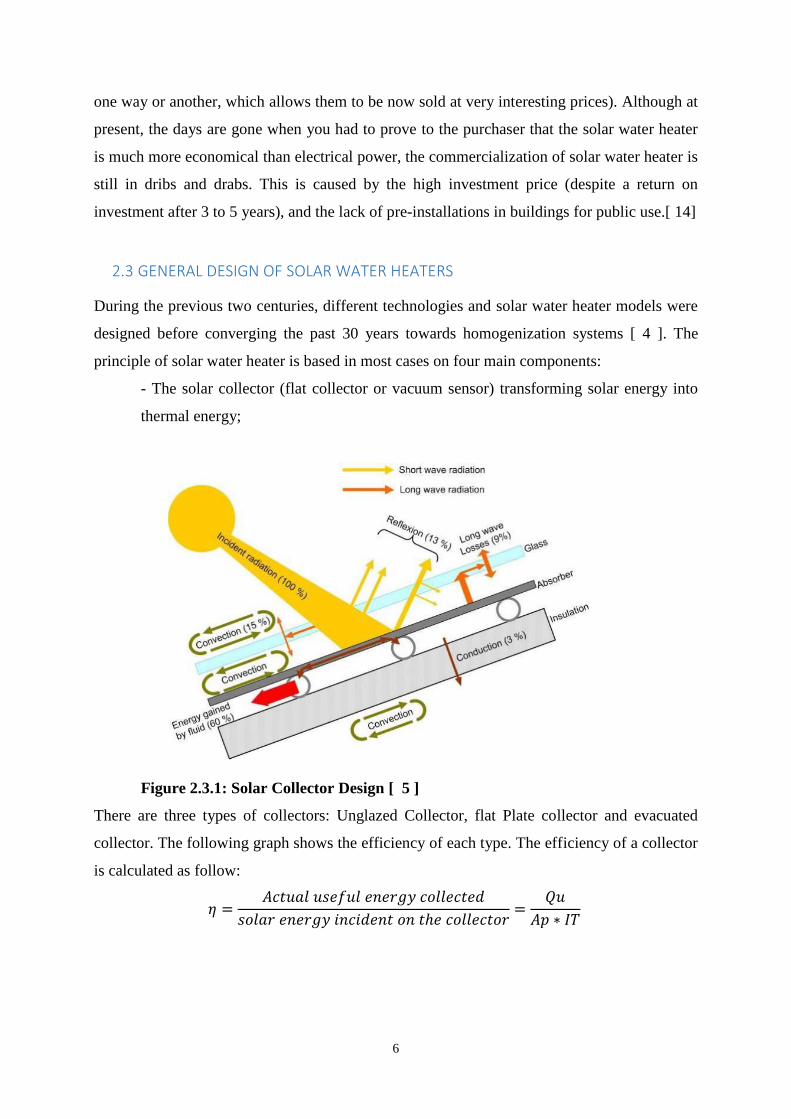
There are three types of collectors: Unglazed Collector, flat Plate collector and evacuated
collector. The following graph shows the efficiency of each type. The efficiency of a collector
is calculated as follow:
7
Figure 2.3.2: Efficiency of different types of collectors [ 5 ]
In addition to the collector a solar water heater is also composed of other
elements that are:
- The energy storage tank (generally storing domestic hot water);
- The heat exchangers that are used in the storage tank;
- Regulating materials, allowing a management of all the system to get the most
energy heat produced by the captures.
There are three types of solar water heater :
1. The Thermosyphon solar water heaters: in this type of solar water heater the regulation
and energy transfer are naturally done by the gravitation of hot water. For this type, the
storage tank must be necessarily above solar collectors;
2. Electrically forced circulation water heater: the circulation of the heat transfer fluid is
forced by an electric pump controlled by a wide system controller manager (for large
facilities demand hot water and the communal buildings).
3. Solar water heaters with integrated tank: this type of solar water heaters are composed
of a tank integrated within the collector and the absorber.
The sensor is part of the primordial solar water heater for converting solar energy into thermal
energy, it would be appropriate to give a brief description of the two sensor types that are
most used all over the world: the flat plate collector and vacuum sensor. The sensor plane is
8
designed on its front face with a window glass letting the sun's rays while imprisoning the
heat created by the absorber (greenhouse effect). The absorber, just a few centimeter below
the glass pane, is a thin sheet of copper or aluminum coated with a layer of black or dark blue
(Selective layer), for transforming the energy solar energy into heat and to transmit this heat
to the heat transfer fluid.
Finally, a thermal plate thermal insulation fiberglass or polyurethane is placed at the rear and
on the side walls of the sensor in order not to let the heat escape to the air. The vacuum sensor
consists of a closed tube, placed entirely under vacuum, or two coaxial tubes (Of different
diameters) between each vacuum.
That lets the sunlight goes to the absorber. The larger the void, the greater are the small
thermal losses. By its high efficiency, the sensor vacuum is increasingly a prominent sensor in
installations providing high temperatures (medium health, hospital and industrial) or those to
be done in limited areas. Architects and customers caring Building aesthetics advocate such as
sensor because it can be installed horizontally (And not 35 ° as the plane sensor) while
preserving the daily maximum absorption of solar energy. As for the control of quality
standards and performance, there are several international organizations and test
Certification sensors that make it available, through In Morocco, the Development Centre of
Renewable Energies DCER also delivers a quality certificate for any water heater solar
Thermosyphon.[ 5 ]
2.4 SOLAR WATER HEATERS WITH INTEGRATED TANK
The production of hot water using solar water heater is one of the largest applications
in solar energy. Solar water heaters that provide between 100 and 200 liters per day of hot
water for about a temperature range of 40-70 ° C have integrated storage tank and collectors.
Plate collectors, concentrators parabolic with and without storing water used in these systems.
Integrated storage system is a simple construction, installation and manipulation. It is
compact, less bulky and aesthetically better than the elements separated, but it is less used
than the latter because the storage tank of hot water presents significant heat loss during the
night and periods of low sunlight. This happens because the total protection of the storage
tank is difficult as it is also the absorptive surface of the solar radiation unlike the system
elements or separate storage tank is completely thermally insulated. New designs aim to
reduce losses before integrating mechanisms to reduce losses not only in the illuminated face
9
but also inside cavities of the headers or on the storage tank surfaces of the water heater with
integrated storage.
Pachern Jansa, tried a SWH with an integrated tank to the collector [ 11 ]. This kind of
SWH is known as a built-in storage (BIS) solar water heater. A simulation model for
evaluating the thermal performance has been done based on the energy balance on the three
primary segments: storage tank, absorber plate and collector channel. The developed BIS
solar water heater involves a sun powered absorber plate of 2.01-m² area which is integrated
into a rectangular stockpiling tank of 213 liter capacity. The rectangular tank is made of
stainless steel sheets. A layered absorber plate is made of a copper sheet which is painted with
dark black matte. It is settled over the tank and afterward secured by a 3-mm glass sheet. An
air gap of 30 mm is left between the glass sheet and the absorber plate. The sides and base of
the tank is thermally protected with 50-mm thick glass-fiber sheets.
T. Muneer led a study that aimed to compare and analyze the performance of stainless
steel and aluminum built-in-storage solar water heaters. He composed and tested a two built-
in-storage solar water heaters, with a capacity of 80 liters, indistinguishable in outline
however with distinctive materials in the storage. The top surface of the two storage tanks
were painted in dark black so that it plays the role of thermal collector and absorb incident
solar radiation. [ 6 ]
The storage water tanks consisted of 1mm thick sheet of base material and had
measurements of 1mx1m, with a depth of 0.08 m. the inlet of Water and outlet valves were
given at the base and top of the two opposite sides of the tanks, separately. And to secure
against heat loss through convection, storage water tanks were covered with 50mm of glass
wool protection on all sides and base and housed in an external metallic box made of 0.5mm
thick zinc iron sheet. The two SWHs have precisely the same design and size, the only
distinction is in the material of the storage tank. The experimental work attempted as a
component of this task included design and improvement of the two solar water heaters and in
addition their operation and data collections over a time of two months.
The investigated data demonstrated that for residential applications, comparing against
gas operated systems, aluminum and stainless steel solar water heaters have separately
demonstrated a payback time of 9.6 and 3.4 years. For industrial applications, where for water
heating, solar energy intends to dislodge furnace oil delivered energy, the fiscal payback
period for the stainless steel and aluminum warmers has been discovered to be proportionate
separately to 3.9 years and 1.4 years.
10
3. THE DOUBLE GLAZING BUILT-IN STORAGE WATER SYSTEM DESIGN
The Double Glazing Built-in Storage water system is a particular system different from
the typical solar water heaters that usually have collector panels and a separated storage tank
mounted on it, this system has a storage integrate within the collector. The absorber plate is in
direct contact with water in the tank. This decision has been made in order to consistently
reduce the cost of construction of the SWH. Solar radiation will go through the first and the
second cover plate. The lower layer of the second cover plate will be in contact with a thin
absorbing film or a selective black coating thermally treated that will absorb solar radiation in
direct contact with water in the tank. This section will represent the design of each part of the
system: The storage water tank, the absorber plate and finally the cover plate.
3.1 COLLECTOR OF THE DOUBLE GLAZING STORAGE WATER HEATER SYSTEM
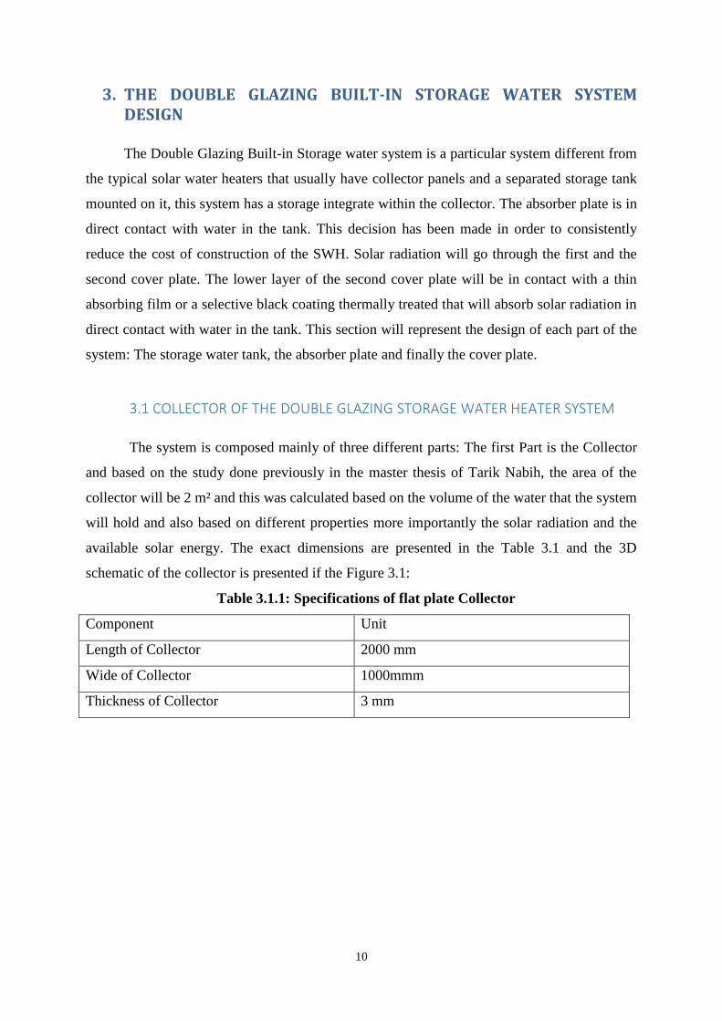
The system is composed mainly of three different parts: The first Part is the Collector
and based on the study done previously in the master thesis of Tarik Nabih, the area of the
collector will be 2 m² and this was calculated based on the volume of the water that the system
will hold and also based on different properties more importantly the solar radiation and the
available solar energy. The exact dimensions are presented in the Table 3.1 and the 3D
schematic of the collector is presented if the Figure 3.1:
Table 3.1.1: Specifications of flat plate Collector
Component Unit
Length of Collector 2000 mm
Wide of Collector 1000mmm
Thickness of Collector 3 mm
11
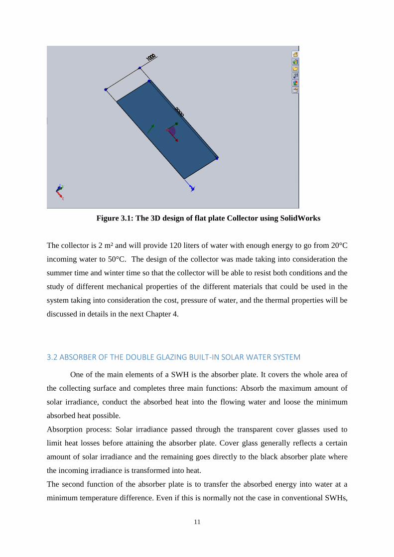
Figure 3.1: The 3D design of flat plate Collector using SolidWorks
The collector is 2 m² and will provide 120 liters of water with enough energy to go from 20°C
incoming water to 50°C. The design of the collector was made taking into consideration the
summer time and winter time so that the collector will be able to resist both conditions and the
study of different mechanical properties of the different materials that could be used in the
system taking into consideration the cost, pressure of water, and the thermal properties will be
discussed in details in the next Chapter 4.
3.2 ABSORBER OF THE DOUBLE GLAZING BUILT-IN SOLAR WATER SYSTEM
One of the main elements of a SWH is the absorber plate. It covers the whole area of
the collecting surface and completes three main functions: Absorb the maximum amount of
solar irradiance, conduct the absorbed heat into the flowing water and loose the minimum
absorbed heat possible.
Absorption process: Solar irradiance passed through the transparent cover glasses used to
limit heat losses before attaining the absorber plate. Cover glass generally reflects a certain
amount of solar irradiance and the remaining goes directly to the black absorber plate where
the incoming irradiance is transformed into heat.
The second function of the absorber plate is to transfer the absorbed energy into water at a
minimum temperature difference. Even if this is normally not the case in conventional SWHs,
12
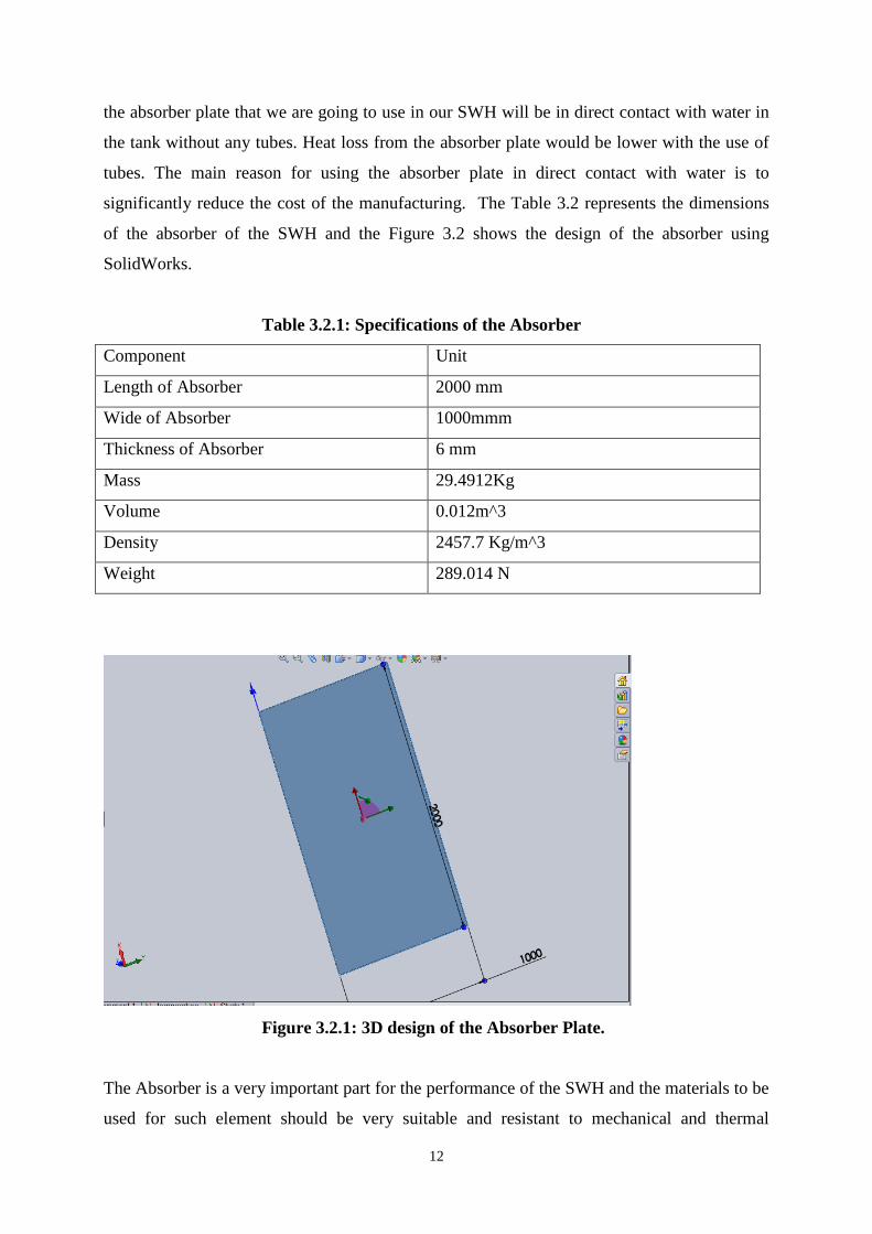
the absorber plate that we are going to use in our SWH will be in direct contact with water in
the tank without any tubes. Heat loss from the absorber plate would be lower with the use of
tubes. The main reason for using the absorber plate in direct contact with water is to
significantly reduce the cost of the manufacturing. The Table 3.2 represents the dimensions
of the absorber of the SWH and the Figure 3.2 shows the design of the absorber using
SolidWorks.
Table 3.2.1: Specifications of the Absorber
Component Unit
Length of Absorber 2000 mm
Wide of Absorber 1000mmm
Thickness of Absorber 6 mm
Mass 29.4912Kg
Volume 0.012m^3
Density 2457.7 Kg/m^3
Weight 289.014 N
Figure 3.2.1: 3D design of the Absorber Plate.
The Absorber is a very important part for the performance of the SWH and the materials to be
used for such element should be very suitable and resistant to mechanical and thermal
13
properties. In general the most used materials for absorber are: Aluminum, Stainless Steel,
Glass, and Copper. Also the Absorber will be covered by a surface of coating that is thermally
treated or with a very thin absorber sheet made of a material with high thermal conductivity.
The next chapter will give more details about the mechanical properties of each material along
with its performance in real situation.
3.3 STORAGE TANK OF THE DOUBLE GLAZING BUILT-IN SOLAR WATER SYSTEM
The Storage tank of the SWH is where water enter at a certain velocity from an inlet
and then is heated in the tank and goes out when needed from an outlet at a certain velocity,
the tank is composed of three layers: external layer, middle layer, and internal layer.
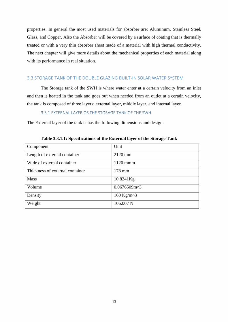
3.3.1 EXTERNAL LAYER OS THE STORAGE TANK OF THE SWH
The External layer of the tank is has the following dimensions and design:
Table 3.3.1.1: Specifications of the External layer of the Storage Tank
Component Unit
Length of external container 2120 mm
Wide of external container 1120 mmm
Thickness of external container 178 mm
Mass 10.8241Kg
Volume 0.0676509m^3
Density 160 Kg/m^3
Weight 106.007 N
14
Figure 3.3.1.1: 3D Design of the External layer of the Storage Tank
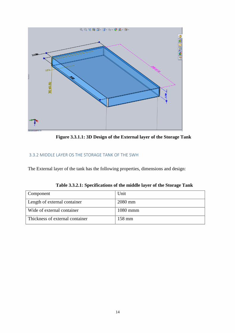
3.3.2 MIDDLE LAYER OS THE STORAGE TANK OF THE SWH
The External layer of the tank has the following properties, dimensions and design:
Table 3.3.2.1: Specifications of the middle layer of the Storage Tank
Component Unit
Length of external container 2080 mm
Wide of external container 1080 mmm
Thickness of external container 158 mm
15
Figure 3.3.2.1: 3D Design of the middle layer of the Storage Tank
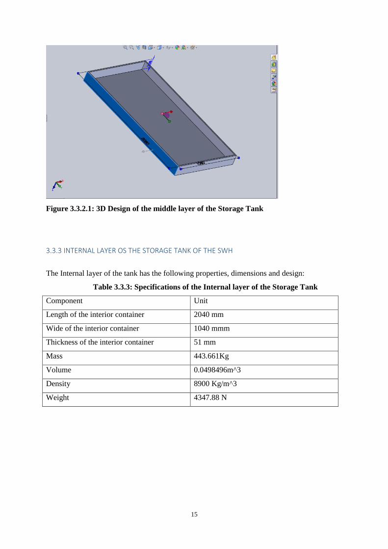
3.3.3 INTERNAL LAYER OS THE STORAGE TANK OF THE SWH
The Internal layer of the tank has the following properties, dimensions and design:
Table 3.3.3: Specifications of the Internal layer of the Storage Tank
Component Unit
Length of the interior container 2040 mm
Wide of the interior container 1040 mmm
Thickness of the interior container 51 mm
Mass 443.661Kg
Volume 0.0498496m^3
Density 8900 Kg/m^3
Weight 4347.88 N
16
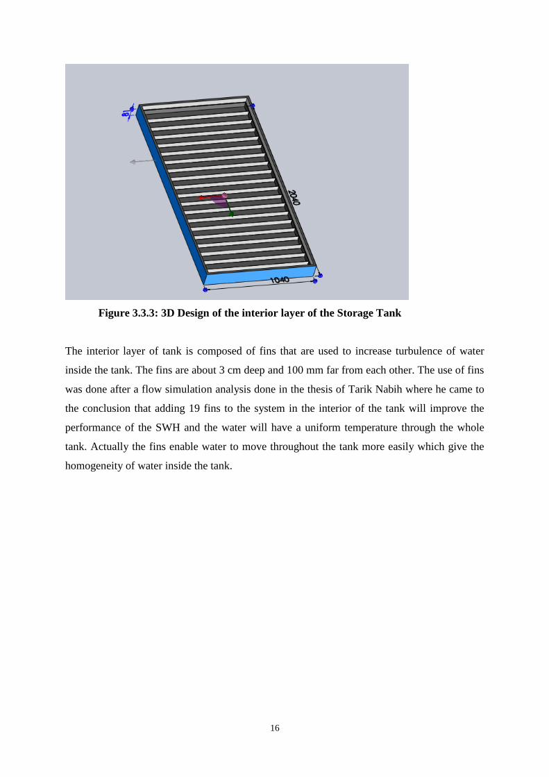
Figure 3.3.3: 3D Design of the interior layer of the Storage Tank
The interior layer of tank is composed of fins that are used to increase turbulence of water
inside the tank. The fins are about 3 cm deep and 100 mm far from each other. The use of fins
was done after a flow simulation analysis done in the thesis of Tarik Nabih where he came to
the conclusion that adding 19 fins to the system in the interior of the tank will improve the
performance of the SWH and the water will have a uniform temperature through the whole
tank. Actually the fins enable water to move throughout the tank more easily which give the
homogeneity of water inside the tank.
17
3.3.4 DESIGN OF SWH SYSTEM
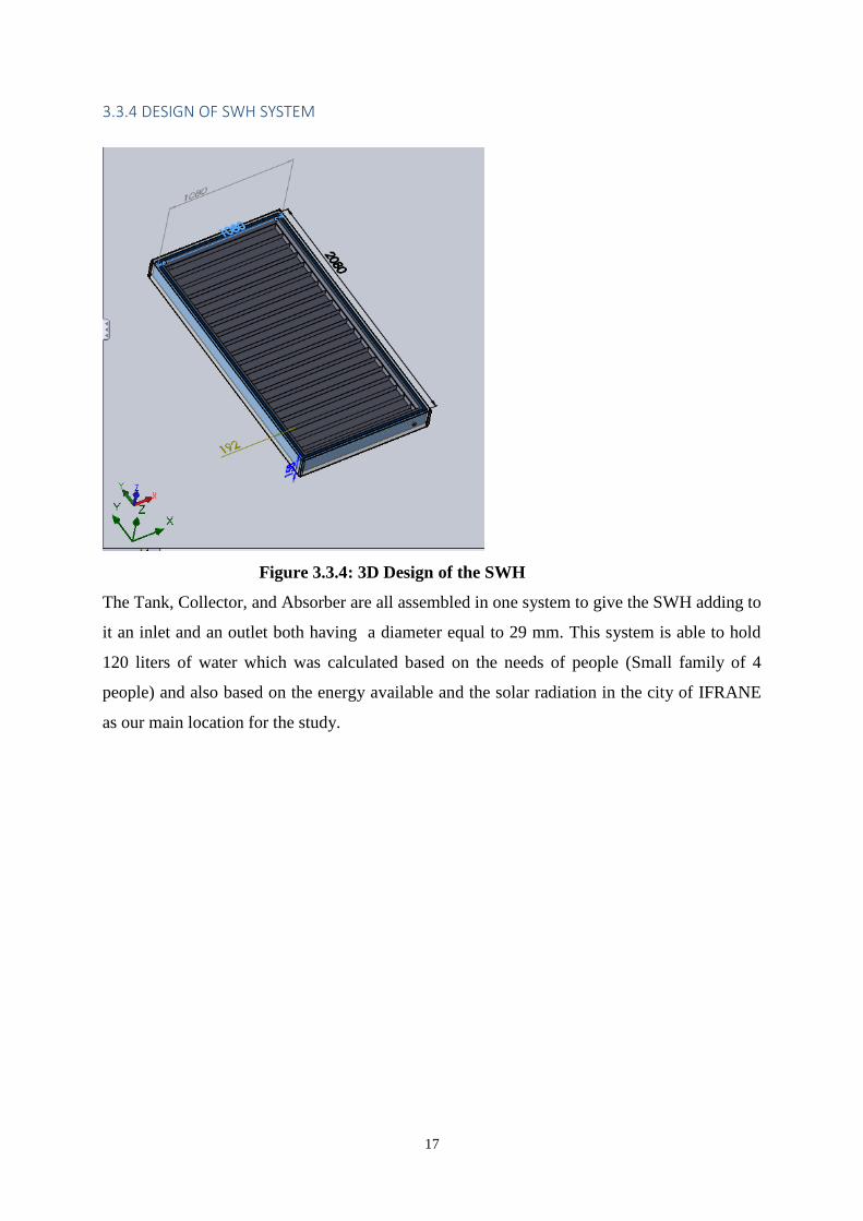
Figure 3.3.4: 3D Design of the SWH
The Tank, Collector, and Absorber are all assembled in one system to give the SWH adding to
it an inlet and an outlet both having a diameter equal to 29 mm. This system is able to hold
120 liters of water which was calculated based on the needs of people (Small family of 4
people) and also based on the energy available and the solar radiation in the city of IFRANE
as our main location for the study.
18
4. THE DOUBLE GLAZING BUILT-IN STORAGE WATER SYSTEM MATERIALS: MECHANICAL PROPERTIES
This section will be an analysis of the mechanical properties of the SWH, the study will
focus on the hydraulic pressure as a load applied to the surface of each part of the system that
is in contact with water. The aim of this study is to choose the best materials that should be
used in our system in order to have the best performance with less costs. First the study
consists of choosing different materials that could be used for each part, find their mechanical
properties: elastic modulus, safety factor, shear modulus, thermal expansion coefficient, and
poison’s ratio in order to generate a stress, displacement and strain analysis on the system.
4.1 DEFINITIONS:
The study will focus mainly on the following mechanical properties, before stating the
mechanical properties of the materials that we will discuss in this project, I will first start by
giving some brief definitions of the most important mechanical properties that I will focus on
in my study: :
Stress: The ratio of applied load to the cross sectional area of a component in tension
and is communicated kilograms/mm
Strain: The measure of the deformation of the material and it has no unit
Modulus of elasticity:
Ultimate Strength (tensile):
The maximum stress a material withstands when subjected to an applied load.
Elastic limit: The point on the stress strain beyond which the material permanently
deforms after removing the load.
Yield strength: The point at which materials exceed the elastic limit and will return to
its origin shape or length if the stress is removed.
19
Poisson ratio:
Safety Factor: is a function of stress and yield strength. It is equal to the division of
the yield strength over the maximum stress in the design.
4.2 PROPERTIES OF POTENTIAL MATERIALS FOR THE ABSROBER PLATE
One of the main elements of a SWH is the absorber plate. It covers the whole area of
the collecting surface and completes three main functions: Absorb the maximum amount of
solar irradiance, conduct the absorbed heat into the flowing water and loose the minimum
absorbed heat possible. In general the most used materials for absorber are: Aluminum, Glass,
and Copper. Also the Absorber will be covered by a surface coating thermally treated or a
very thin absorber sheet made of a material with high thermal conductivity.
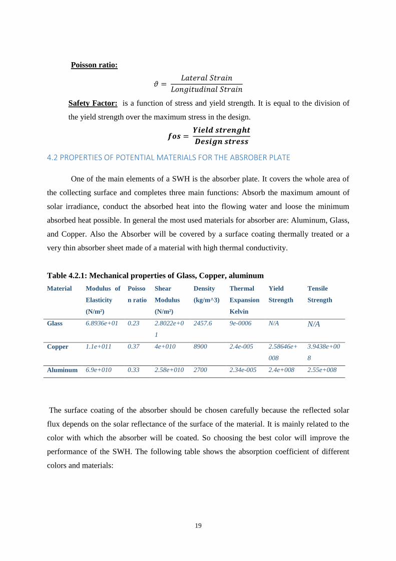
Table 4.2.1: Mechanical properties of Glass, Copper, aluminum
Material Modulus of
Elasticity
(N/m²)
Poisso
n ratio
Shear
Modulus
(N/m²)
Density
(kg/m^3)
Thermal
Expansion
Kelvin
Yield
Strength
Tensile
Strength
Glass 6.8936e+01 0.23 2.8022e+0
1
2457.6 9e-0006 N/A N/A
Copper 1.1e+011 0.37 4e+010 8900 2.4e-005 2.58646e+
008
3.9438e+00
8
Aluminum 6.9e+010 0.33 2.58e+010 2700 2.34e-005 2.4e+008 2.55e+008
The surface coating of the absorber should be chosen carefully because the reflected solar
flux depends on the solar reflectance of the surface of the material. It is mainly related to the
color with which the absorber will be coated. So choosing the best color will improve the
performance of the SWH. The following table shows the absorption coefficient of different
colors and materials:
20
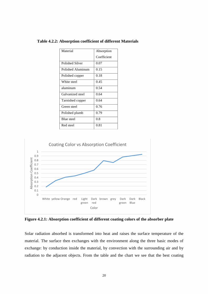
Table 4.2.2: Absorption coefficient of different Materials
Figure 4.2.1: Absorption coefficient of different coating colors of the absorber plate
Solar radiation absorbed is transformed into heat and raises the surface temperature of the
material. The surface then exchanges with the environment along the three basic modes of
exchange: by conduction inside the material, by convection with the surrounding air and by
radiation to the adjacent objects. From the table and the chart we see that the best coating
0
0.1
0.2
0.3
0.4
0.5
0.6
0.7
0.8
0.9
1
White yellow Orange red Lightgreen
Darkred
brown grey Darkgreen
DarkBlue
Black
Ab
sorp
tio
n C
oef
fici
ent
Color
Coating Color vs Absorption Coefficient
Material Absorption
Coefficient
Polished Silver 0.07
Polished Aluminum 0.15
Polished copper 0.18
White steel 0.45
aluminum 0.54
Galvanized steel 0.64
Tarnished copper 0.64
Green steel 0.76
Polished plumb 0.79
Blue steel 0.8
Red steel 0.81
21
layer should be black steel coating because it has the highest absorption coefficient equal to
0.94 which will not allow a high heat loss between the absorber and the water tank
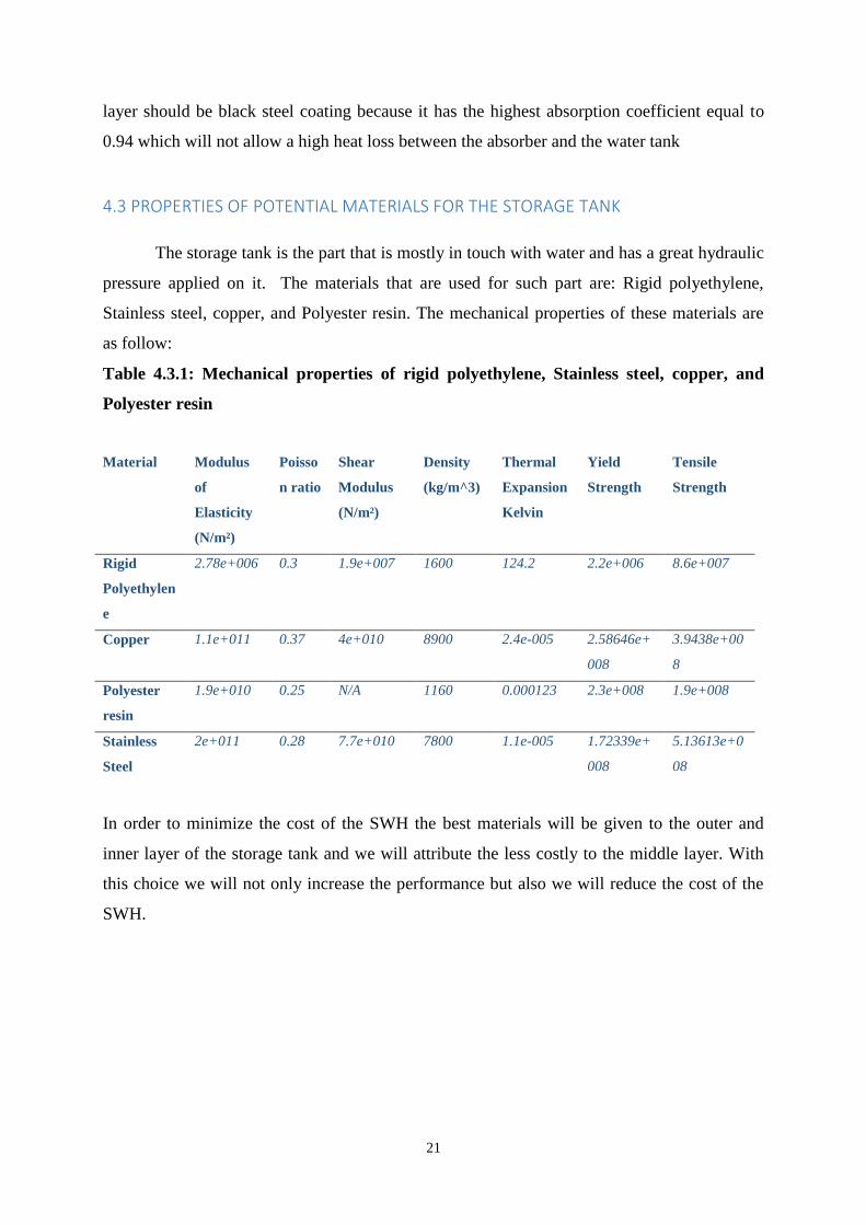
4.3 PROPERTIES OF POTENTIAL MATERIALS FOR THE STORAGE TANK
The storage tank is the part that is mostly in touch with water and has a great hydraulic
pressure applied on it. The materials that are used for such part are: Rigid polyethylene,
Stainless steel, copper, and Polyester resin. The mechanical properties of these materials are
as follow:
Table 4.3.1: Mechanical properties of rigid polyethylene, Stainless steel, copper, and
Polyester resin
Material Modulus
of
Elasticity
(N/m²)
Poisso
n ratio
Shear
Modulus
(N/m²)
Density
(kg/m^3)
Thermal
Expansion
Kelvin
Yield
Strength
Tensile
Strength
Rigid
Polyethylen
e
2.78e+006 0.3 1.9e+007 1600 124.2 2.2e+006 8.6e+007
Copper 1.1e+011 0.37 4e+010 8900 2.4e-005 2.58646e+
008
3.9438e+00
8
Polyester
resin
1.9e+010 0.25 N/A 1160 0.000123 2.3e+008 1.9e+008
Stainless
Steel
2e+011 0.28 7.7e+010 7800 1.1e-005 1.72339e+
008
5.13613e+0
08
In order to minimize the cost of the SWH the best materials will be given to the outer and
inner layer of the storage tank and we will attribute the less costly to the middle layer. With
this choice we will not only increase the performance but also we will reduce the cost of the
SWH.
22
5. SOLIDWORKS SIMULATION OF THE DOUBLE GLAZING BUILT-IN STORAGE WATER SYSTEM
5.1 SOLIDWORKS COMPUTER-AIDED DESIGN
SolidWorks is a 3D modeler that use a parametric design. Created in 1993 by the
eponymous American publisher, SolidWorks was purchased June 24, 1997 by Dassault
systems 2. Among the largest organizations using SolidWorks, Michelin include, AREVA, ,
Mega Bloks, Axiom, ME2C, MMC Packaging Equipment, SACMO, Leboulch, Patek
Philippe ,Robert Renaud and the French Ministry of Education. It generates three types of
files related to three basic concepts: the part, assembly and drawing. These files are related.
Any change on any level whatsoever is passed to all relevant files. A comprehensive file
containing all relating to the same system is a digital model. Many software complete the
SolidWorks editor. Business-oriented utilities (sheet metal, wood, construction ...), but also
mechanical simulation applications or computer graphics work from the elements of the
virtual model. [ 2 ]
5.2 SOLIDWORKS SIMULATION
SolidWorks offers a set of simulation solutions that allow engineers to define a
virtual environment with real conditions to test product designs before manufacturing phase.
Also the Simulation in SolidWorks perform tests that take into account a wide range of
settings throughout the design process, such as resistance, static and dynamic response, the
movement of the assembly, heat transfer and fluid dynamics, to evaluate product performance
and make decisions to improve the quality and safety of the product. Simulation reduces costs
and speeds time to market by reducing the number of physical prototypes needed before the
start of production. SolidWorks Simulation helps engineers and designers to innovate, test and
develop new concepts based on a maximum of relevant information.
23
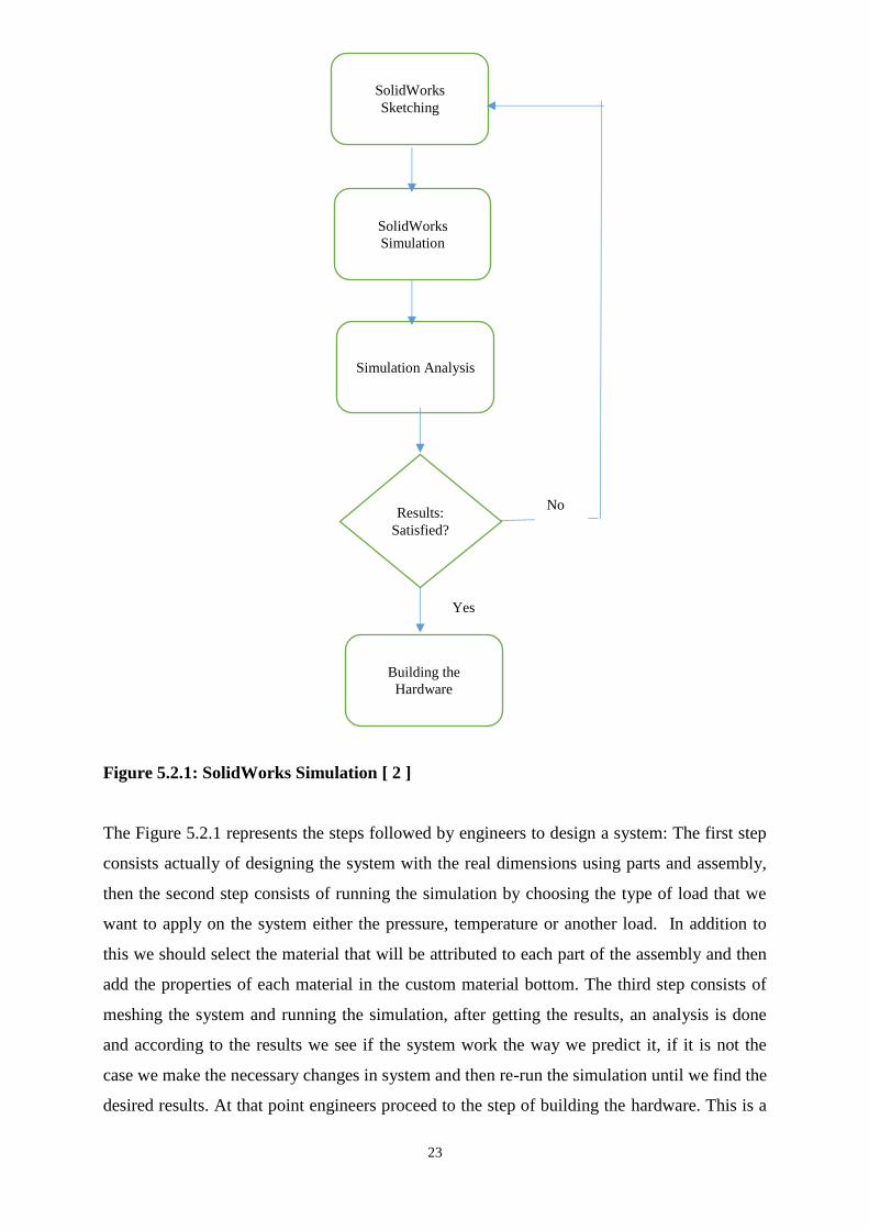
Figure 5.2.1: SolidWorks Simulation [ 2 ]
The Figure 5.2.1 represents the steps followed by engineers to design a system: The first step
consists actually of designing the system with the real dimensions using parts and assembly,
then the second step consists of running the simulation by choosing the type of load that we
want to apply on the system either the pressure, temperature or another load. In addition to
this we should select the material that will be attributed to each part of the assembly and then
add the properties of each material in the custom material bottom. The third step consists of
meshing the system and running the simulation, after getting the results, an analysis is done
and according to the results we see if the system work the way we predict it, if it is not the
case we make the necessary changes in system and then re-run the simulation until we find the
desired results. At that point engineers proceed to the step of building the hardware. This is a
SolidWorks
Sketching
SolidWorks
Simulation
Simulation Analysis
Results:
Satisfied?
Building the
Hardware
Yes
No
24
very efficient method to avoid all the additional cost of prototypes and waste time in
designing each time a prototype.
.5.3 SIMULATION ANALYSIS OF THE DOUBLE GLAZING BUILT-IN STORAGE WATER
SYSTEM:
A simulation analysis is done on the system of double glazing built-in solar water
heater measuring the hydraulic pressure under specified boundary conditions in order to
examine the impact of the water on the absorber. A finite element analysis is done to compare
the stress, displacement and strain of the investigated SWH’s materials.
Since, we are investigating different materials we need to run different simulations depending
on the specified material. How does the pressure impact the different types of the system? A
comparison of these scenarios is illustrated below.
The resulting plots will illustrate the different parts of the system’s stress, strain and
displacement. First we start by measuring the strength of a part of the system at which it will
fail. Therefore, in order to determine if a part will fail or not, we must choose a failure theory.
SolidWorks simulation uses the von‐Mises or maximum‐distortion‐energy theory to predict
the structure failure. In this analysis, the von‐Mises equivalent stress was solved by the
software and it is presented in figures below for each part of the system. This later can be
compared to the material’s yield strength to foresee yielding of the structure.
5.3.1 SIMULATION ANALYSIS OF THE ABSORBER PLATE
Since, we are investigating three materials which include glass, aluminum, and copper,
we need to run three simulations depending on the specified material. How does the pressure
impact the different types of the absorber? A comparison of these scenarios is illustrated
below.
25
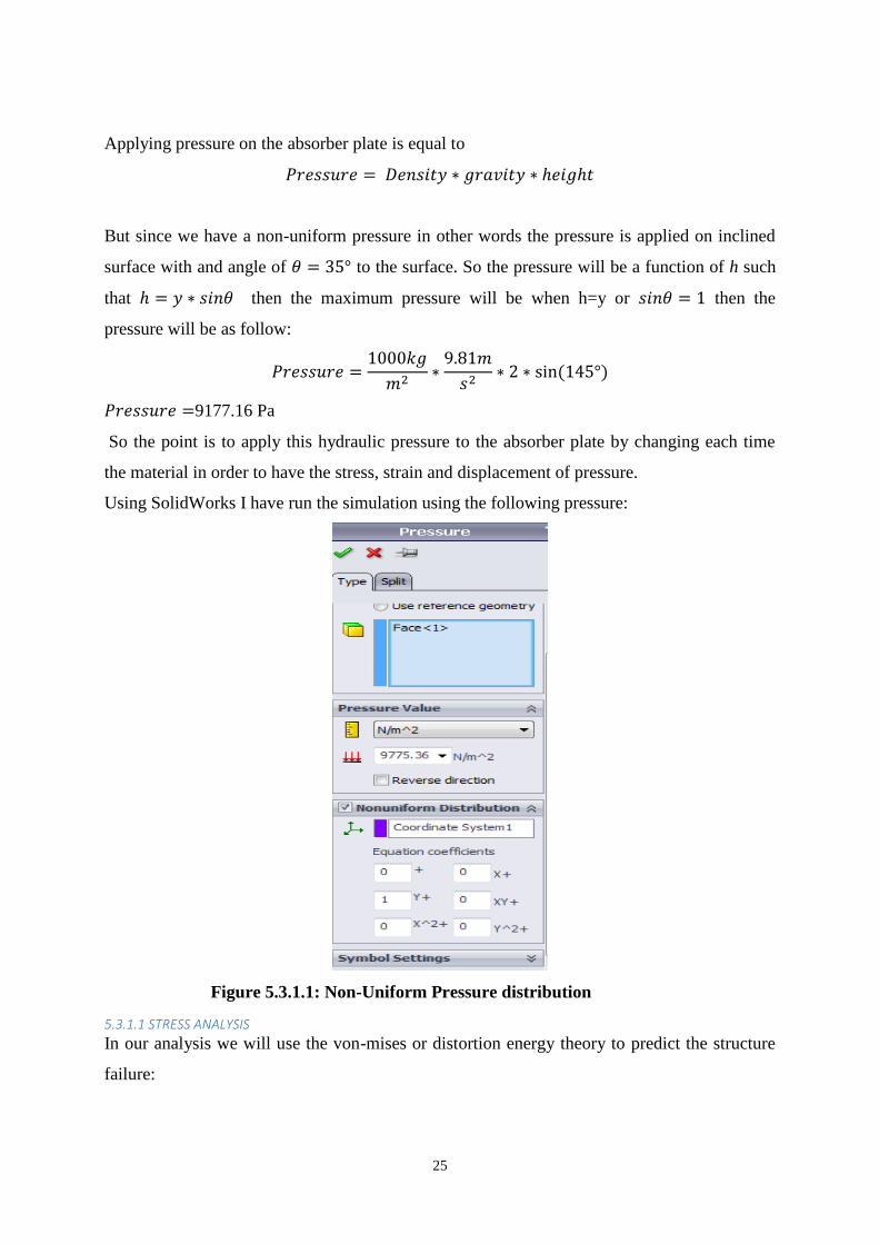
Applying pressure on the absorber plate is equal to
But since we have a non-uniform pressure in other words the pressure is applied on inclined
surface with and angle of to the surface. So the pressure will be a function of h such
that then the maximum pressure will be when h=y or then the
pressure will be as follow:
9177.16 Pa
So the point is to apply this hydraulic pressure to the absorber plate by changing each time
the material in order to have the stress, strain and displacement of pressure.
Using SolidWorks I have run the simulation using the following pressure:
Figure 5.3.1.1: Non-Uniform Pressure distribution
5.3.1.1 STRESS ANALYSIS
In our analysis we will use the von-mises or distortion energy theory to predict the structure
failure:
26
According to the von-mises’s theory, a ductile solid will yield or deform when the distortion
energy density reaches a critical value for that material.
The distortion density is:
√
√
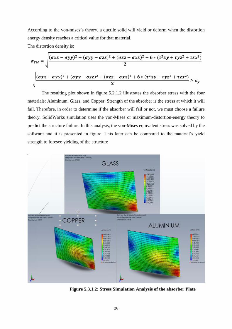
The resulting plot shown in figure 5.2.1.2 illustrates the absorber stress with the four
materials: Aluminum, Glass, and Copper. Strength of the absorber is the stress at which it will
fail. Therefore, in order to determine if the absorber will fail or not, we must choose a failure
theory. SolidWorks simulation uses the von‐Mises or maximum‐distortion‐energy theory to
predict the structure failure. In this analysis, the von‐Mises equivalent stress was solved by the
software and it is presented in figure. This later can be compared to the material’s yield
strength to foresee yielding of the structure
Figure 5.3.1.2: Stress Simulation Analysis of the absorber Plate
27
The figure 5.3.1.2 shows the stress of the absorber with different materials, from the figure we
can see that the glass is the best material to be used for the absorber in terms of stress because
it resists pressure more than aluminum and copper do. Also we see that the one that can
deform more easily is Copper.
In the case of Aluminum absorber, the maximum von‐Mises stress is about 1.6091e+008
N/m². The material’s yield strength is 2.58646e+008N/m². In order to know if the material
will fail or not we need to calculate the safety factor and compare it to the common and stable
safety factor that equals 10.
‐
Since we found that the safety factor is less than 10, it means that Aluminum Absorber will
fail and will not be able to resist the pressure of water. So we discard this material.
In the case of copper absorber, the maximum von‐Mises stress is about 1.36942e+008 N/m²
The material’s yield strength is 2.58646e+008 N/m². Same thing we will calculate the safety
factor:
Like Aluminum absorber, the copper absorber will also fail to the hydraulic pressure. So we
discard also this material.
In the case of glass absorber, the maximum von‐Mises stress is about 1.6091e+008 N/m²
The material’s yield strength is 3.5 e+009 N/m². Same thing we will calculate the safety
factor:
21.75
Since the factor of safety of Glass is greater than 10 then glass will be the best material to use
in the absorber in order to have the maximum efficiency without any pressure failure.
After the stress simulation analysis I have run a displacement analysis to see how the
hydraulic pressure propagates inside the absorber and the figure 5.2.1.3 summarizes the
results obtained for the four materials (Glass, Copper, and Aluminum)
28
Table 5.3.1.2: Simulation Analysis of the absorber Plate
Material Safety Factor
Aluminum 1.4915
Copper 1.89
Glass 21.75
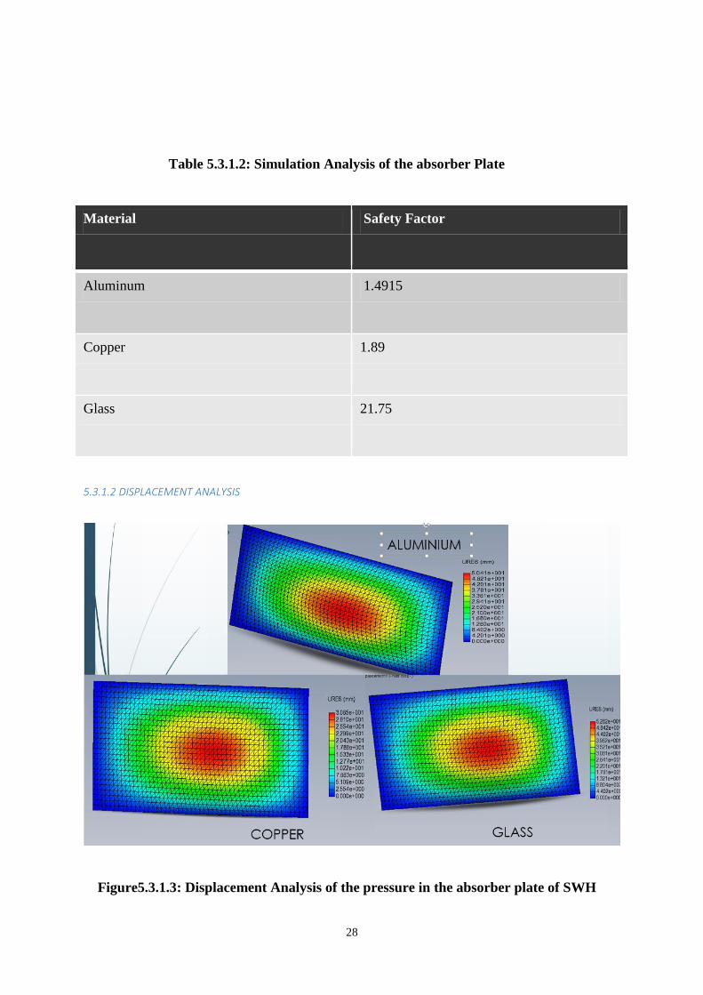
5.3.1.2 DISPLACEMENT ANALYSIS
Figure5.3.1.3: Displacement Analysis of the pressure in the absorber plate of SWH
29
Displacement analysis is presented in Figure 5.2.1.4. Glass has the lowest displacement ratio
followed by copper, and Aluminum. They seem to have the same displacement but actually
the maximum displacement occurs in the absorber made of and it is equal to 5.282e+001N/m².
Hence, the pressure load has more impact on aluminum absorber.
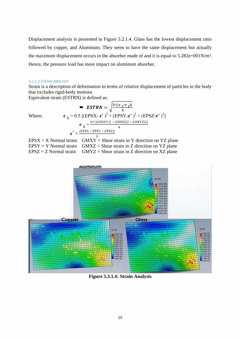
5.2.1.3 STRAIN ANALYSIS
Strain is a description of deformation in terms of relative displacement of particles in the body
that excludes rigid-body motions
Equivalent strain (ESTRN) is defined as:
√
Where: . S -
S -
S -
=
.
* =
S S S
EPSX = X Normal strain GMXY = Shear strain in Y direction on YZ plane
EPSY = Y Normal strain GMXZ = Shear strain in Z direction on YZ plane
EPSZ = Z Normal strain GMYZ = Shear strain in Z direction on XZ plane
Figure 5.3.1.4: Strain Analysis
30
The most important requirement for the absorber application is the ability to resist high
pressure. Hence, Glass should be more commonly used. However, high strength copper that
pre-stressed and reinforced can also be applied.
5.2.1.4 RESULTS AND DISCUSSION
After running the simulation of the hydraulic pressure on the absorber plate we
obtained the stress, strain and displacement of each material and we have seen that all the
three materials: Aluminum and copper fail to resist the pressure while the glass did not and it
was actually the best one to resist the pressure and the one with the least displacement and
Strain. Then in order for the absorber to be efficient and reduce the heat losses, we should use
as a material for this part Glass with a black coating.
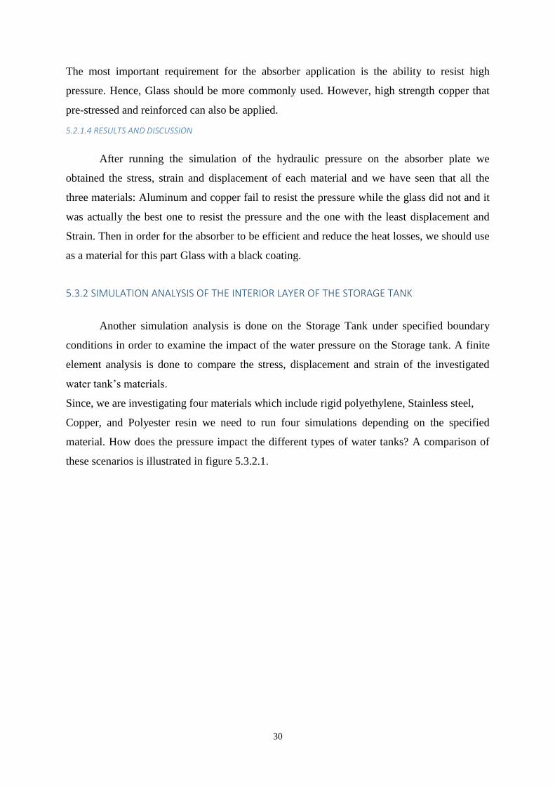
5.3.2 SIMULATION ANALYSIS OF THE INTERIOR LAYER OF THE STORAGE TANK
Another simulation analysis is done on the Storage Tank under specified boundary
conditions in order to examine the impact of the water pressure on the Storage tank. A finite
element analysis is done to compare the stress, displacement and strain of the investigated
water tank’s materials.
Since, we are investigating four materials which include rigid polyethylene, Stainless steel,
Copper, and Polyester resin we need to run four simulations depending on the specified
material. How does the pressure impact the different types of water tanks? A comparison of
these scenarios is illustrated in figure 5.3.2.1.
31
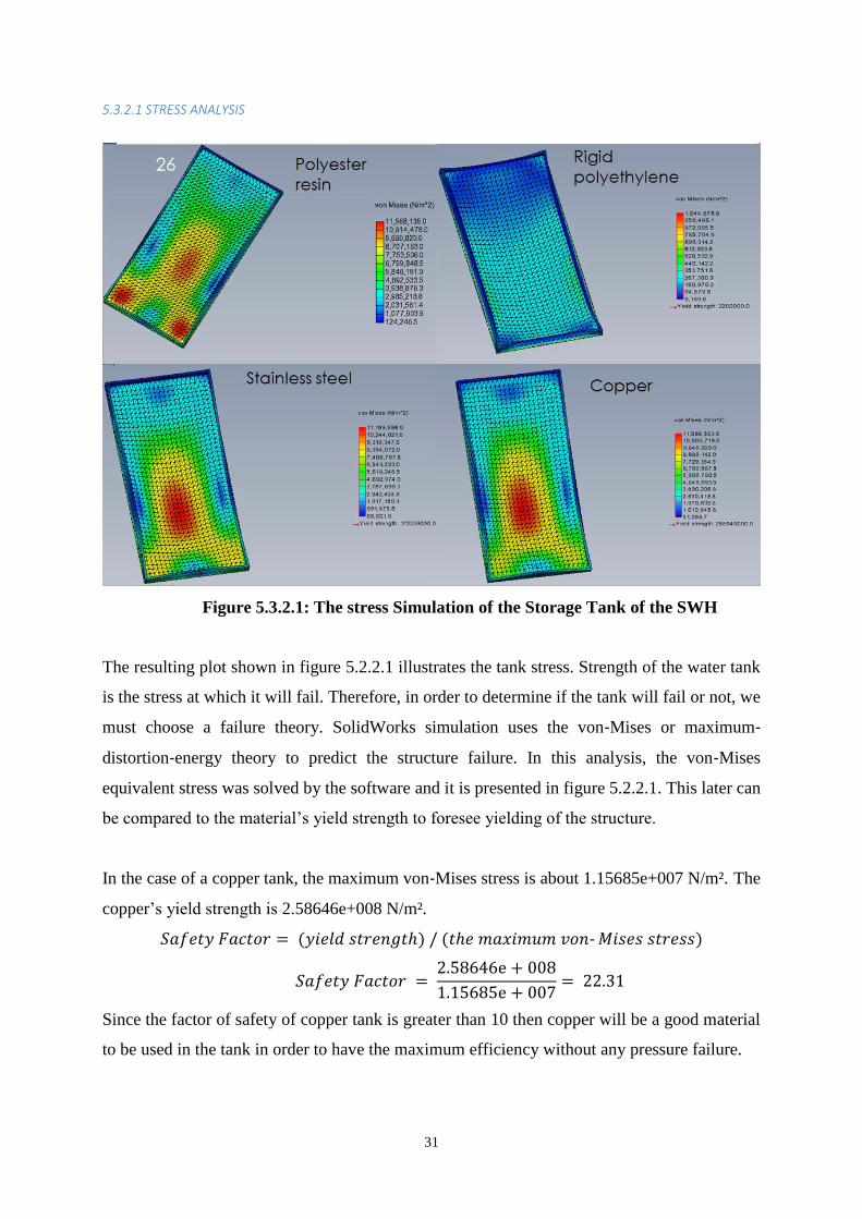
5.3.2.1 STRESS ANALYSIS
Figure 5.3.2.1: The stress Simulation of the Storage Tank of the SWH
The resulting plot shown in figure 5.2.2.1 illustrates the tank stress. Strength of the water tank
is the stress at which it will fail. Therefore, in order to determine if the tank will fail or not, we
must choose a failure theory. SolidWorks simulation uses the von‐Mises or maximum‐
distortion‐energy theory to predict the structure failure. In this analysis, the von‐Mises
equivalent stress was solved by the software and it is presented in figure 5.2.2.1. This later can
be compared to the material’s yield strength to foresee yielding of the structure.
In the case of a copper tank, the maximum von‐Mises stress is about 1.15685e+007 N/m². The
copper’s yield strength is 2.58646e+008 N/m².
‐
Since the factor of safety of copper tank is greater than 10 then copper will be a good material
to be used in the tank in order to have the maximum efficiency without any pressure failure.
32
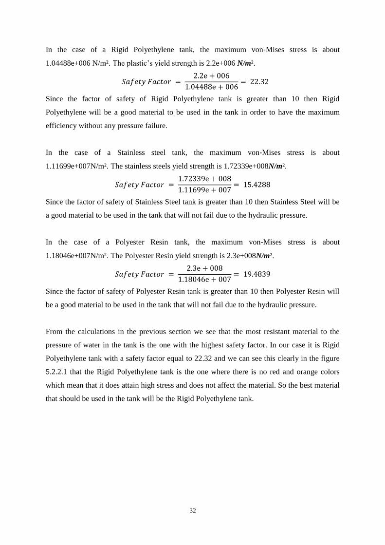
In the case of a Rigid Polyethylene tank, the maximum von‐Mises stress is about
1.04488e+006 N/m². The plastic’s yield strength is 2.2e+006 N/m².
Since the factor of safety of Rigid Polyethylene tank is greater than 10 then Rigid
Polyethylene will be a good material to be used in the tank in order to have the maximum
efficiency without any pressure failure.
In the case of a Stainless steel tank, the maximum von‐Mises stress is about
1.11699e+007N/m². The stainless steels yield strength is 1.72339e+008N/m².
Since the factor of safety of Stainless Steel tank is greater than 10 then Stainless Steel will be
a good material to be used in the tank that will not fail due to the hydraulic pressure.
In the case of a Polyester Resin tank, the maximum von‐Mises stress is about
1.18046e+007N/m². The Polyester Resin yield strength is 2.3e+008N/m².
Since the factor of safety of Polyester Resin tank is greater than 10 then Polyester Resin will
be a good material to be used in the tank that will not fail due to the hydraulic pressure.
From the calculations in the previous section we see that the most resistant material to the
pressure of water in the tank is the one with the highest safety factor. In our case it is Rigid
Polyethylene tank with a safety factor equal to 22.32 and we can see this clearly in the figure
5.2.2.1 that the Rigid Polyethylene tank is the one where there is no red and orange colors
which mean that it does attain high stress and does not affect the material. So the best material
that should be used in the tank will be the Rigid Polyethylene tank.
33
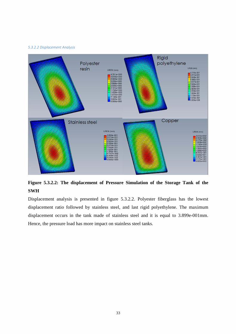
5.3.2.2 Displacement Analysis
Figure 5.3.2.2: The displacement of Pressure Simulation of the Storage Tank of the
SWH
Displacement analysis is presented in figure 5.3.2.2. Polyester fiberglass has the lowest
displacement ratio followed by stainless steel, and last rigid polyethylene. The maximum
displacement occurs in the tank made of stainless steel and it is equal to 3.899e-001mm.
Hence, the pressure load has more impact on stainless steel tanks.
34
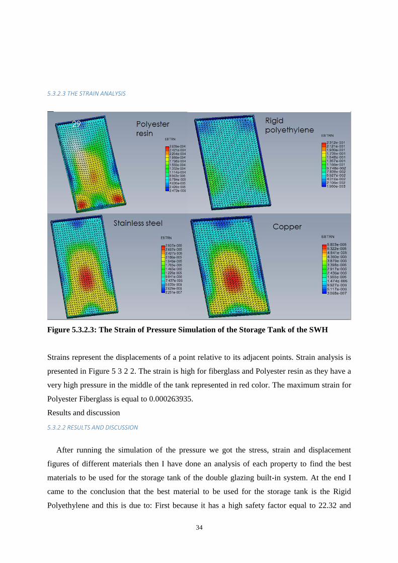
5.3.2.3 THE STRAIN ANALYSIS
Figure 5.3.2.3: The Strain of Pressure Simulation of the Storage Tank of the SWH
Strains represent the displacements of a point relative to its adjacent points. Strain analysis is
presented in Figure 5 3 2 2. The strain is high for fiberglass and Polyester resin as they have a
very high pressure in the middle of the tank represented in red color. The maximum strain for
Polyester Fiberglass is equal to 0.000263935.
Results and discussion
5.3.2.2 RESULTS AND DISCUSSION
After running the simulation of the pressure we got the stress, strain and displacement
figures of different materials then I have done an analysis of each property to find the best
materials to be used for the storage tank of the double glazing built-in system. At the end I
came to the conclusion that the best material to be used for the storage tank is the Rigid
Polyethylene and this is due to: First because it has a high safety factor equal to 22.32 and

35
second because it has the least displacement of all the other three materials: stainless steel,
fiberglass and Polyester resin which means that the pressure load has less impact on the rigid
polyethylene storage tank than it has on other studied materials. The last point is about the
strain analysis, after analyzing the simulation we see that the best out of the four materials is
the Rigid Polyethylene so for a better performance and good efficiency the best material to be
used in the inner layer of the storage tank should be Rigid Polyethylene.
36
6. ECONOMIC ANALYSIS OF THE DOUBLE GLAZING SOLAR WATER HEATER
A SWH system is known for its long life that goes up to 20 years. Contrary to the idea that
people might think, SWH does not require huge investment but in the opposite this system
start to be rentable after only few years and it is the best alternative to the electric water heater
that require an enormous expenses in the electrical bills.
In this section I will do a comparison of the cost of the SWH materials that could be used in
such a system
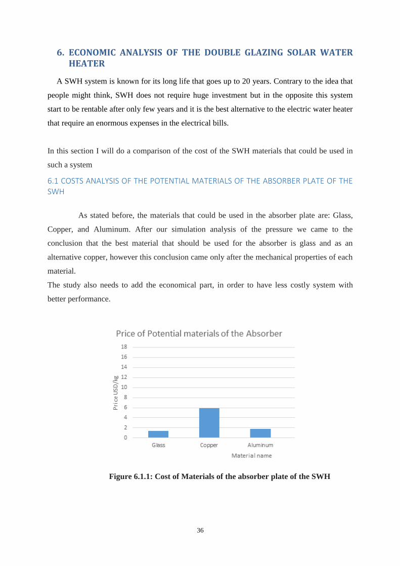
6.1 COSTS ANALYSIS OF THE POTENTIAL MATERIALS OF THE ABSORBER PLATE OF THE SWH
As stated before, the materials that could be used in the absorber plate are: Glass,
Copper, and Aluminum. After our simulation analysis of the pressure we came to the
conclusion that the best material that should be used for the absorber is glass and as an
alternative copper, however this conclusion came only after the mechanical properties of each
material.
The study also needs to add the economical part, in order to have less costly system with
better performance.
Figure 6.1.1: Cost of Materials of the absorber plate of the SWH
37
From the Graph 6.1 we see that the least costly material is glass. So in addition to its good
mechanical properties, Glass is the less costly which will allow us to make the final choice
about the material to be used in the absorber plate
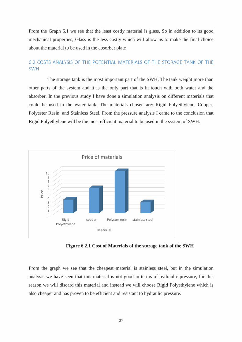
6.2 COSTS ANALYSIS OF THE POTENTIAL MATERIALS OF THE STORAGE TANK OF THE SWH
The storage tank is the most important part of the SWH. The tank weight more than
other parts of the system and it is the only part that is in touch with both water and the
absorber. In the previous study I have done a simulation analysis on different materials that
could be used in the water tank. The materials chosen are: Rigid Polyethylene, Copper,
Polyester Resin, and Stainless Steel. From the pressure analysis I came to the conclusion that
Rigid Polyethylene will be the most efficient material to be used in the system of SWH.
Figure 6.2.1 Cost of Materials of the storage tank of the SWH
From the graph we see that the cheapest material is stainless steel, but in the simulation
analysis we have seen that this material is not good in terms of hydraulic pressure, for this
reason we will discard this material and instead we will choose Rigid Polyethylene which is
also cheaper and has proven to be efficient and resistant to hydraulic pressure.
0123456789
10
RigidPolyethylene
copper Polyster resin stainless steel
Pri
ce
Material
Price of materials
38
6.3 CONCLUSION AND DISCUSSION
From the economic analysis, I have compared between the costs of different materials.
The first comparison was made between potential materials that could be used in the absorber
plate, the materials discussed are: Glass, Copper, and Aluminum. The most expensive
material is copper and the cheapest is glass. So the best choice for our system would be glass.
For the comparison of the potential materials that could be used in storage water tank we had:
Rigid Polyethylene, Copper, Polyester Resin, and Stainless Steel. I have found that the
cheaper material is stainless steel so automatically our choice should be stainless steel, but
since in the pressure analysis still did not perform well I will choose rigid polyethylene which
is not very expensive in comparison to Copper and Polyester Resin.
39
7. CONCLUSION
Despite the technology development, the question of energy is emerging as one of our
major concerns. Some of the sources are depleted, others pollute our environment. Our energy
needs are increasing every day. For this reason humanity should lean toward renewable
energies that are almost inexhaustible like wind and sun. One major energy that could be used
easily is the solar energy and nowadays it is used for many purposes: Solar water heating,
solar air hating...etc. This capstone project consists of finding a solution to improve the
performance of an innovative double glazing solar water heaters for home usage with a
capacity of usage of four people maximum.
The main goal of this project is to emphasize the performance of the system and
simulate the behavior and mechanical properties of solar water heater using the available and
efficient materials.
Using SolidWorks (Section5) I have been able to study the mechanical performance of
different materials especially for the absorber and the storage tank. After getting the stress,
strain and displacement plots and tables, I analyzed the results and I came to the conclusion
that the best materials to be used for the system would be: Glass for the absorber and Rigid
Polyethylene for the storage tank. But conducting only a mechanical simulation analysis was
not enough to decide which materials to be used because after all our main goal is to
maximize the performance and minimize the costs. I have conducted also an economic
analysis of the materials in order to compare and choose the best out of them. For the potential
materials of the absorber plate I found that the cheapest material was glass and it is in
accordance with our simulation study since the glass performed well under pressure
conditions so the choice was to choose glass as our main material for the absorber and coat it
with a black coating that has absorption coefficient equal to 0.94. Last for the comparison of
potential materials that could be used for the storage tank I have found that the cheapest
material is stainless steel but since it did not perform well under pressure conditions the
choice was to choose Rigid Polyethylene since is not expensive and it has demonstrated a
good resistance to hydraulic pressure.
40
BIBLIOGRAPHY
[ 1 ] Ahasanul Haque Chowdhury, Design and Animation of Automated Alternative Solar
Water Heater System at the BRAC University Roof Top by Using SolidWorks and Implement
the Controller Using GAL Technology , May, 2012 Retrieved from:
http://dspace.bracu.ac.bd/bitstream/handle/10361/1914/Design%20and%20animation%20of%
20automation.pdf?sequence=1
[ 2 ] An Introduction to Engineering Design With SolidWorks®, SolidWorks Corporation
1995-2008, Retrieved from :
http://edweb.tusd.k12.az.us/mcalhoun/Solidworks%20Activities.pdf
[ 3 ] BILLY ANAK SUP, EFFECT OF ABSORBER PLATE MATERIAL ON FLAT PLATE
COLLECTOR EFFICIENCY, DECEMBER 2010 retrieved from :
http://umpir.ump.edu.my/2868/1/CD5897.pdf
[ 4 ] Christopher A. Homola, PE, Solar Domestic Hot Water Heating Systems Design,
Installation and Maintenance retrieved from:
http://www.solarthermalworld.org/sites/gstec/files/story/2015-03-
14/noh_solarwtrhtg_pres.pdf
[ 5 ] Hottel HC, Woertz BB. The performance of flat-plate solar heat collectors.. 1942, Trans
ASME, Vol. 64, pp. 94-102.
[ 6 ] Jean Cariou: Solar Water Heater , August 2010, Supervised and edited by Peter Meisen
President, Global Energy Network Institute retrieved from:
http://www.geni.org/globalenergy/research/solar-water-heaters/solar-water-heater.pdf
[ 7 ] Jurgen Fechter, Solar water heaters- Ferritic Solution, 2006 retrieved from:
http://www.outokumpu.com/SiteCollectionDocuments/Solarwaterheaters-Ferritic-Solution-
ISSF.pdf
[ 8 ] Kothari, D.P., Singal, K. C. and Ranjan, Rakesh. Renewable Energy Sources and
Emerging Technologies.
[ 9 ] Mechanical properties of Materials, 1999 http://ocw.mit.edu/courses/materials-science-
and-engineering/3-11-mechanics-of-materials-fall-1999/modules/props.pdf
[ 10 ] Mukherje, D. Fundamentals of Renewable Energy Systems. s.l. : New Age
International, 2007. 9788122415407.
41
[ 11 ] Pachern Jansa,. A Simulation Model for Predicting the Performance of a Built-in-
Storage Solar Water Heater. 4, October-December 2004, Thammasat International Journal of
Science and Technology, Vol. 9.
[ 12 ] Performance of a Built-in-Storage Solar Water Heater Comparison of aluminum and
stainless steel built-in-storage solar water heater. Asif, M, Currie, J and Muneer, T. 4, 2007,
Building services engineering research & technology, Vol. 28, pp. 337-346. 0143-6244.
[ 13 ] Solar Water Heating: Domestic and Industrial Applications (Energy Engineering)
retrieved from : http://what-when-how.com/energy-engineering/solar-water-heating-domestic-
and-industrial-applications-energy-engineering/
[ 14 ] ZOHRA ETTAIK. SOLAR WATER HEATERS IN MOROCCO, 8 June 2012.
Retrieved from: http://www.shamci.net/wpcontent/uploads/2013/09/Morocco_ArSol_country-
report.pdf
42
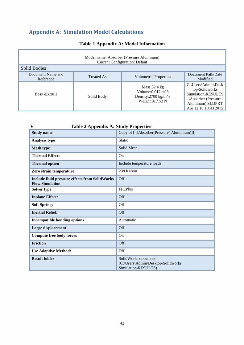
Appendix A: Simulation Model Calculations
Table 1 Appendix A: Model Information
V Table 2 Appendix A: Study Properties
Study name Copy of [ [[Absorber(Pressure( Aluminium)]]]
Analysis type Static
Mesh type Solid Mesh
Thermal Effect: On
Thermal option Include temperature loads
Zero strain temperature 298 Kelvin
Include fluid pressure effects from SolidWorks
Flow Simulation
Off
Solver type FFEPlus
Inplane Effect: Off
Soft Spring: Off
Inertial Relief: Off
Incompatible bonding options Automatic
Large displacement Off
Compute free body forces On
Friction Off
Use Adaptive Method: Off
Result folder SolidWorks document
(C:\Users\Admin\Desktop\Solidworks
Simulation\RESULTS)
Model name: Absorber (Pressure Aluminum)
Current Configuration: Défaut
Solid Bodies
Document Name and
Reference Treated As Volumetric Properties
Document Path/Date
Modified
Boss.-Extru.1
Solid Body
Mass:32.4 kg
Volume:0.012 m^3
Density:2700 kg/m^3
Weight:317.52 N
C:\Users\Admin\Desk
top\Solidworks
Simulation\RESULTS
\Absorber (Pressure
Aluminum).SLDPRT
Apr 12 10:18:43 2015
43
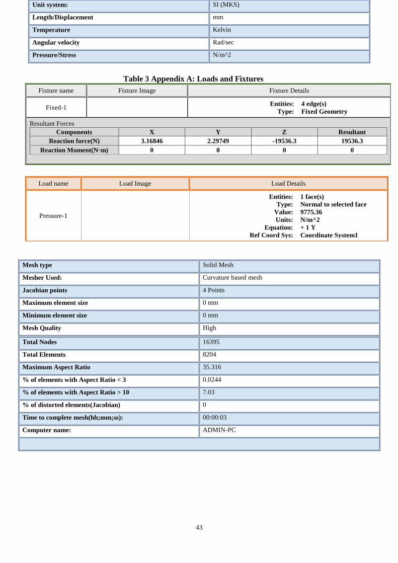
Unit system: SI (MKS)
Length/Displacement mm
Temperature Kelvin
Angular velocity Rad/sec
Pressure/Stress N/m^2
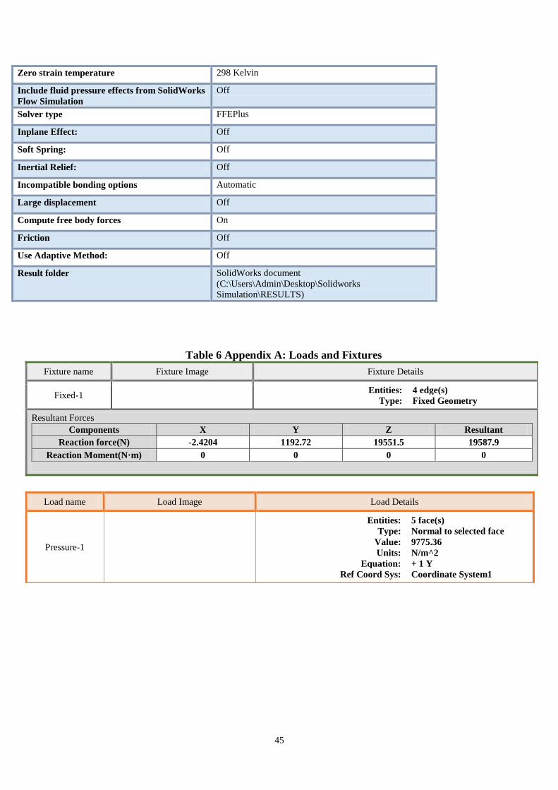
Table 3 Appendix A: Loads and Fixtures
Fixture name Fixture Image Fixture Details
Fixed-1 Entities: 4 edge(s)
Type: Fixed Geometry
Resultant Forces
Components X Y Z Resultant
Reaction force(N) 3.16846 2.29749 -19536.3 19536.3
Reaction Moment(N·m) 0 0 0 0
Load name Load Image Load Details
Pressure-1
Entities: 1 face(s)
Type: Normal to selected face
Value: 9775.36
Units: N/m^2
Equation: + 1 Y
Ref Coord Sys: Coordinate System1
Mesh type Solid Mesh
Mesher Used: Curvature based mesh
Jacobian points 4 Points
Maximum element size 0 mm
Minimum element size 0 mm
Mesh Quality High
Total Nodes 16395
Total Elements 8204
Maximum Aspect Ratio 35.316
% of elements with Aspect Ratio < 3 0.0244
% of elements with Aspect Ratio > 10 7.03
% of distorted elements(Jacobian) 0
Time to complete mesh(hh;mm;ss): 00:00:03
Computer name: ADMIN-PC
44
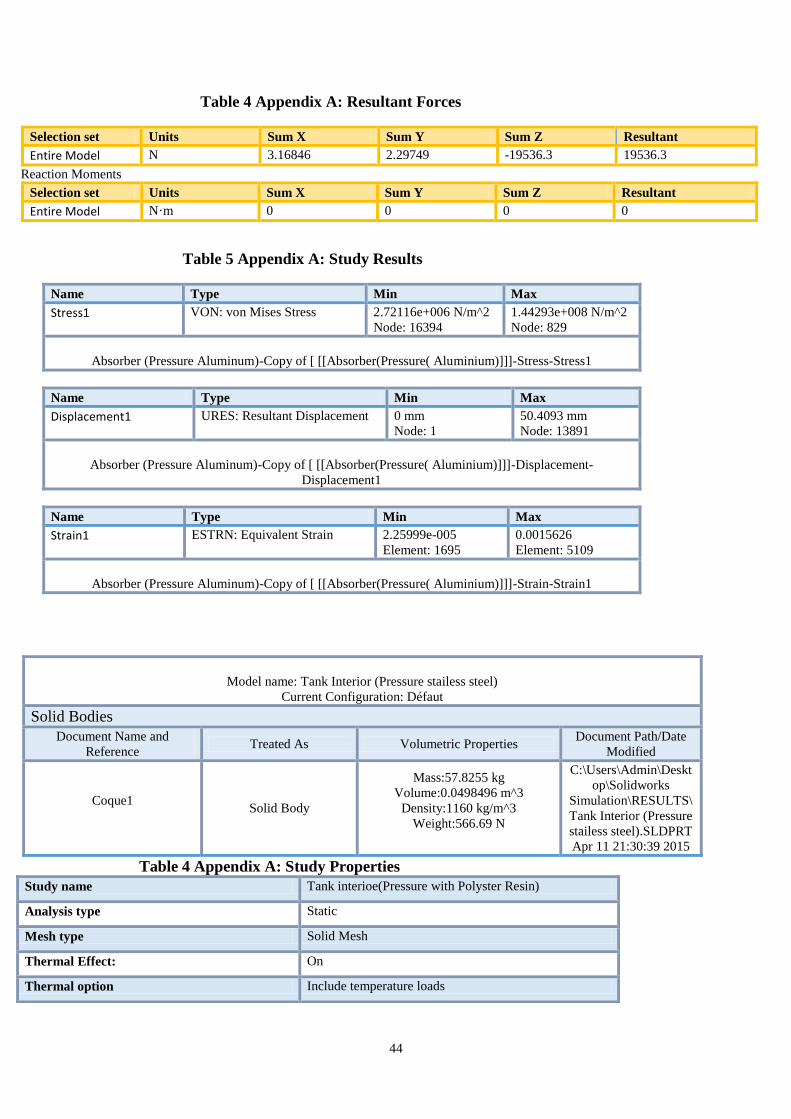
Table 4 Appendix A: Resultant Forces
Selection set Units Sum X Sum Y Sum Z Resultant
Entire Model N 3.16846 2.29749 -19536.3 19536.3
Reaction Moments
Selection set Units Sum X Sum Y Sum Z Resultant
Entire Model N·m 0 0 0 0
Table 4 Appendix A: Study Properties
Study name Tank interioe(Pressure with Polyster Resin)
Analysis type Static
Mesh type Solid Mesh
Thermal Effect: On
Thermal option Include temperature loads
Table 5 Appendix A: Study Results
Name Type Min Max
Stress1 VON: von Mises Stress 2.72116e+006 N/m^2
Node: 16394
1.44293e+008 N/m^2
Node: 829
Absorber (Pressure Aluminum)-Copy of [ [[Absorber(Pressure( Aluminium)]]]-Stress-Stress1
Name Type Min Max
Displacement1 URES: Resultant Displacement 0 mm
Node: 1
50.4093 mm
Node: 13891
Absorber (Pressure Aluminum)-Copy of [ [[Absorber(Pressure( Aluminium)]]]-Displacement-
Displacement1
Name Type Min Max
Strain1 ESTRN: Equivalent Strain 2.25999e-005
Element: 1695
0.0015626
Element: 5109
Absorber (Pressure Aluminum)-Copy of [ [[Absorber(Pressure( Aluminium)]]]-Strain-Strain1
Model name: Tank Interior (Pressure stailess steel)
Current Configuration: Défaut
Solid Bodies
Document Name and
Reference Treated As Volumetric Properties
Document Path/Date
Modified
Coque1
Solid Body
Mass:57.8255 kg
Volume:0.0498496 m^3
Density:1160 kg/m^3
Weight:566.69 N
C:\Users\Admin\Deskt
op\Solidworks
Simulation\RESULTS\
Tank Interior (Pressure
stailess steel).SLDPRT
Apr 11 21:30:39 2015
45
Zero strain temperature 298 Kelvin
Include fluid pressure effects from SolidWorks
Flow Simulation
Off
Solver type FFEPlus
Inplane Effect: Off
Soft Spring: Off
Inertial Relief: Off
Incompatible bonding options Automatic
Large displacement Off
Compute free body forces On
Friction Off
Use Adaptive Method: Off
Result folder SolidWorks document
(C:\Users\Admin\Desktop\Solidworks
Simulation\RESULTS)
Table 6 Appendix A: Loads and Fixtures
Fixture name Fixture Image Fixture Details
Fixed-1 Entities: 4 edge(s)
Type: Fixed Geometry
Resultant Forces
Components X Y Z Resultant
Reaction force(N) -2.4204 1192.72 19551.5 19587.9
Reaction Moment(N·m) 0 0 0 0
Load name Load Image Load Details
Pressure-1
Entities: 5 face(s)
Type: Normal to selected face
Value: 9775.36
Units: N/m^2
Equation: + 1 Y
Ref Coord Sys: Coordinate System1
46
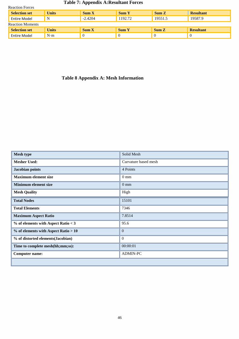
Table 7: Appendix A:Resultant Forces Reaction Forces
Selection set Units Sum X Sum Y Sum Z Resultant
Entire Model N -2.4204 1192.72 19551.5 19587.9
Reaction Moments
Selection set Units Sum X Sum Y Sum Z Resultant
Entire Model N·m 0 0 0 0
Table 8 Appendix A: Mesh Information
Mesh type Solid Mesh
Mesher Used: Curvature based mesh
Jacobian points 4 Points
Maximum element size 0 mm
Minimum element size 0 mm
Mesh Quality High
Total Nodes 15101
Total Elements 7346
Maximum Aspect Ratio 7.8514
% of elements with Aspect Ratio < 3 95.6
% of elements with Aspect Ratio > 10 0
% of distorted elements(Jacobian) 0
Time to complete mesh(hh;mm;ss): 00:00:01
Computer name: ADMIN-PC
47
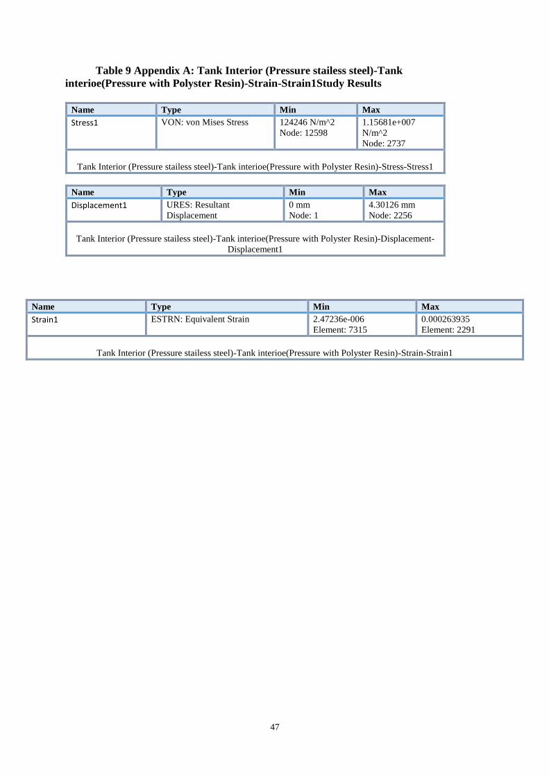
Table 9 Appendix A: Tank Interior (Pressure stailess steel)-Tank
interioe(Pressure with Polyster Resin)-Strain-Strain1Study Results
Name Type Min Max
Stress1 VON: von Mises Stress 124246 N/m^2
Node: 12598
1.15681e+007
N/m^2
Node: 2737
Tank Interior (Pressure stailess steel)-Tank interioe(Pressure with Polyster Resin)-Stress-Stress1
Name Type Min Max
Displacement1 URES: Resultant
Displacement
0 mm
Node: 1
4.30126 mm
Node: 2256
Tank Interior (Pressure stailess steel)-Tank interioe(Pressure with Polyster Resin)-Displacement-
Displacement1
Name Type Min Max
Strain1 ESTRN: Equivalent Strain 2.47236e-006
Element: 7315
0.000263935
Element: 2291
Tank Interior (Pressure stailess steel)-Tank interioe(Pressure with Polyster Resin)-Strain-Strain1