Embed Size (px)
Citation preview
The influence of fibre length, diameter and concentration on the impact
performance of long glass-fibre reinforced Polyamide 6,6.
J. L. Thomason
University of Strathclyde, Department of Mechanical Engineering, 75 Montrose Street,
Glasgow G1 1XJ, United Kingdom.
Keywords: A Polymer-matrix composites (PMCs), B Mechanical properties, B Impact
behaviour, E Injection moulding
Abstract
Results of an investigation of the mechanical performance of injection moulded long
glass-fibre reinforced polyamide 6,6 composites are presented. The glass-fibre content
in these composites was varied over the range of 10-50% by weight using fibres with
average diameters of 10, 14 and 17 μm. Impact testing was carried out at -40, 23 and
80°C on dry-as-moulded and boiling water conditioned samples. The results from these
long fibre composites are compared with standard extrusion compounded short glass-
fibre materials. Data on the influence of fibre diameter, fibre concentration, residual
fibre length, hydrothermal conditioning and testing temperature on the composite
performance in notched and unnotched pendulum impact tests and multiaxial
instrumented impact tests are presented and discussed. All of the above parameters are
shown to have significant influence on impact performance. However, the level of these
effects is shown to depend on which type of impact test is being considered.
1
Introduction
In recent years there has been strong growth in the use of long-glass-fibre thermoplastic
composite systems in semi-structural and engineering applications. These thermoplastic
matrix composite systems combine ease of processing with property advantages such as
enhanced toughness and an unlimited shelf life. Furthermore, their intrinsic recyclability
is rapidly being recognised as a strong driving force for their further application. Their
potential for high-volume processing combined with high levels of end use performance
and associated lower manufacturing costs has spurred the current expansion of research
and development activities on thermoplastic matrix composites. Glass-fibre reinforced
polyamides are excellent composite materials in terms of their high levels of mechanical
performance and temperature resistance. The mechanical performance of these
composites results from a combination of the fibre and matrix properties and the ability
to transfer stresses across the fibre-matrix interface. Variables such as the fibre content,
diameter, orientation and the interfacial strength are of prime importance to the final
balance of properties exhibited by these injection moulded thermoplastic composites [1-
7].
Short fibre reinforced thermoplastics have been used in the automotive industry for
many years and there has recently been a strong growth in the use of polyamide based
materials in under-the-hood applications [8]. More recently, there has been an
increasing growth in the use of long fibre thermoplastic composite systems in semi-
structural and engineering applications. It is interesting to note that the growth rates for
polypropylene based long fibre compounds has far exceeded that of other long fibre
thermoplastic systems over the last decade. This has occurred despite the fact that many
of the early developments and long fibre thermoplastic products were based on
polyamide polymers [9-12]. It may well be that part of the background to this
2
phenomenon lies in the excellent levels of profitability, processibility and performance
of these materials. Achieving the correct balance of these �3P�s� is critical to the
success of any product in its appropriate market. Notwithstanding these facts there has
been considerable discussion recently that the next major long fibre development may
be in thermoplastic systems based on higher performance resins than polypropylene.
Glass-fibre reinforced polyamides are excellent composite materials, however, the
mechanical properties of polyamide based composites decrease markedly upon the
absorption of water and other polar fluids [13-15]. There also exist a number of well
documented differences in the structure-performance relationships of short fibre
reinforced polyamide and polypropylene composites and it can be expected that there
will also be differences when comparing these resins reinforced with long fibres.
In this report data are presented on the mechanical performance of long fibre reinforced
polyamide 6,6 which may be relevant to the above discussion. Injection moulded long
fibre reinforced polyamide 6,6 samples have been prepared with a range of fibre
contents (0-50 % weight) and a sizing chemistry optimized for polyamide reinforcement.
These long fibre compounds have been produced with glass fibres having average fibre
diameters of 10, 14 and 17 μm. Mechanical performance has been determined for both
the �dry-as-moulded� state (DaM) and after hydrolytic and temperature conditioning and
compared with reference short fibre composites based on 10 μm diameter fibre in the
same polymer matrix. Data on the influence of the above variables on the residual fibre
length and fibre orientation distribution in the moulded composites and the composite
modulus and strength have been presented previously [16,17]. In this paper data on the
influence of the above conditioning environments and micromechanical parameters on
the composite notched and unnotched impact performance are presented and discussed.
3

Experimental
The glass samples used for the production of the long glass-fibre pellets were continuous
Advantex® glass (boron free E-glass) Type 30
® packages produced on a single
production bushing. The glass was coated with sizing formulation R43S, which is a
polyamide compatible sizing optimized for continuous glass products. Samples (LF10,
LF14, LF17) were produced with a range of fibre contents using nominal fibre diameters
of 10, 14, 17 μm and linear density (tex) of 1200, 2400, 3500 g/km as previously
described [16,17]. Reference short fibre compounds (SF10) were produced using
DS1123 a nominal 10 μm fibre diameter chopped glass product coated with polyamide
sizing optimized for chopped glass production. The polyamide 6,6 (PA6,6) used for
composite production was DuPont Zytel 101. Reference samples of the unreinforced
resin were also included. Given that the matrix in the fibre reinforced materials
experiences an extra heat cycle, reference resin samples were moulded from resin which
had been run one time through the extruder with the same temperature profile as applied
during the composite pellet production step.
Long fibre reinforced pellets were produced using a standard pultrusion type process [16]
where the continuous glass was fed into an impregnation unit consisting of a heated
oblong box containing a number of spreader bars and a circular exit die of fixed diameter.
The impregnation unit was attached to, and fed by, a single screw extruder which
delivered polymer melt to the unit at a rate appropriate to the pulling speed of the glass
(30 m/min) and the desired final glass:resin ratio of the pellets. The temperature of the
molten resin was maintained between 300-310°C in the impregnation unit. After exiting
the die the resin impregnated glass was cooled in a water bath before passing through a
pulling and chopping operation. Nominal pellet chop length was 12.5 mm. For the short
fibre compound, the chopped glass bundles and pre-dried PA6,6 pellets were dry blended
4
by weight to the appropriate glass content and compounded on a single screw extruder
(2.5 inch, 3.75:1, 24:1 L/D screw). Set point temperatures were 288-293°C for
compounding. The compounds were moulded into test bars on a 200-ton Cincinnati
Milacron moulding machine. Set point temperatures were 293-299°C for moulding, at a
mould temperature of 93°C.
Izod and Charpy impact properties were measured on 10 specimens in accordance with
the procedures in ASTM D-256 and ASTM D-4812. Instrumented impact testing was
conducted using the procedures described in ASTM D3763 including a tup diameter of
12.7 mm (0.5 in.) and a supporting diameter of 38 mm (1.5 in.). Test samples were
moulded discs of 51 mm (2 in.) diameter and 3.2 mm (0.125 in.) thickness. Tests were
performed at a speed of 2.23 m/s (7.33 ft/s) with a drop weight of 15.9 kg (35 lbs) using
an Instron Dynatup 9250HV instrumented impact tester. Unless otherwise stated, all
mechanical property testing was performed at 23°C and at a relative humidity of 50%.
Fibre length, diameter, and orientation distributions were determined by image analysis
and optical microscopy as previously described [16].
Results
The results for the weight average residual fibre length in the moulded composites are
presented in Figure 1, where the error bars indicate the 95% confidence limits on the
averages. It is clear that pultruded �long fibre� (LF) compounds deliver significantly
longer fibres to the moulded composite in comparison to the extruded short fibre (SF)
compound. It is also clear that there exist significant trends for fibre length versus fibre
content in Figure 1. The residual fibre length decreases strongly with increasing fibre
content. As indicated in Figure 1 the data are reasonably well fit by a linear relationship
with the slope of the line for the LF compounds being considerably greater than that
5

observed for SF PA6,6 based compounds [13]. The data in Figure 1 also indicate that
the absolute level of retained fibre length is dependent on the average fibre diameter in
the composites with thinner fibres ending up shorter in the composite for any fixed
value of fibre content. The dependence of the composite modulus and stiffness on the
above parameters have been presented and discussed in previous papers. In summary
there was no modulus dependence found on fibre length or diameter with a strong linear
dependence of modulus on fibre volume fraction [16]. In contrast the strength and
elongation to failure of these composites was shown to be significantly dependent on the
residual fibre length, fibre diameter and fibre concentration [17].
The trends observed in notched impact for Izod and Charpy tests are shown in Figures 2
and 3. Composite notched impact is highly dependent on fibre content and exhibited a
strong linear increase over the 10-30% fibre content range. Above 30% fibre content the
notched impact continued to increase, however, there is some indication that the rate of
increase is lower in the high fibre content region. Extrapolation of the data in Figure 2
and 3 towards zero fibre content does not intercept the value for the unreinforced resin
but is much closer to a value of zero. Interestingly there are also significant differences
in the PA6,6 resin value of notched impact depending on the thermal history. The value
for the polymer sample which has been extruded prior to moulding, and therefore has a
thermal history more comparable with the composite matrix, appears to be more in line
with the composite data. There also appears to be little significant effect of fibre
diameter on the notched impact of these LFPA composites, although there is some
indication that the LF10 performance is slightly lower than the other samples. A highly
significant observation is that the use of LF compounds gives an approximately 50%
higher level of notched impact performance over the SF reference. This �long fibre�
effect is already well known to give some its greatest benefits to notched impact in PP
6
based compounds where the LF/SF ratio is often in the 2-3x range [18,19], significantly
greater than observed here with LFPA.
The data for notched Charpy impact at �40°C in Figure 4 reveals no drop in
performance of the LFPA samples in comparison to the room temperature results,
whereas the PA6,6 resin and the SFPA reference sample both give significantly lower
notched impact performance at �40°C. The results for notched Charpy impact measured
at 80°C in Figure 5 show trends similar, in terms of fibre content, to those observed in at
-40°C and 23°C. The results the PA6,6 matrix polymer alone have increased
significantly due to testing above the glass transition temperature of the polymer which
is in the range of 50-75°C depending on the measurement technique and the moisture
content [20]. There is also some difference to be observed in the results in Figure 6 due
to the fibre diameter. Both LF17 and LF14 notched impact have increased by a similar
amount at the higher testing temperature and show clear indication of a leveling off in
performance above 40% fibre content. The LF10 samples showed little change in
notched impact performance at the higher testing temperature and consequently fall
significantly below LF14 and LF17 in Figure 5.
The data for unnotched Izod and Charpy impact are shown in Figures 6 and 7. As has
been previously observed with SFPA [13-15], the trends in unnotched impact are quite
different from those in notched impact. Addition of even very small amount of
reinforcement drastically reduces the unnotched performance of the PA6,6 polymer
which gave �no breaks� in both unnotched tests. In SFPA a minimum has been observed
to occur in the 2-4% wt range [13], all of the composites in this study have significantly
higher glass contents. Consequently only increasing unnotched impact with increasing
glass content is observed in the fibre content range of this study. In the case of
7
unnotched Izod there is a fairly linear increase in performance, in the case of unnotched
Charpy this is also the case for the LF14 and LF17 samples, however, for LF10 there is
some evidence of a step increase at around 25-30% fibre content. It is also clear in
Figures 6 and 7 that the fibre diameter has a significant influence on the composite
unnotched impact performance, with finer fibres delivering higher unnotched impact at
any fixed fibre content, across the whole range of the study. Finally it is also very
interesting to note that the performance level of the SF10 reference sample in unnotched
impact is not significantly different to its LF10 equivalent. Thus the effect of fibre
length on PA6,6 based composite impact properties is principally an improvement in
notched impact and not unnotched impact.
The data for the Charpy unnotched impact strength after boiling water conditioning
presented in Figure 8 also shows dramatically different trends than the DaM data in
Figure 7. The data for the LF samples all exhibit an apparently constant Charpy
unnotched value of 85±5 kJ/m2 with only one exception (LF10 lowest glass content
sample). This level is significantly above the DaM results in Figure 7 with the greatest
differences at lower fibre contents. Furthermore the SF10 reference samples show a
significantly higher level of unnotched impact after conditioning than the LF10
equivalent.
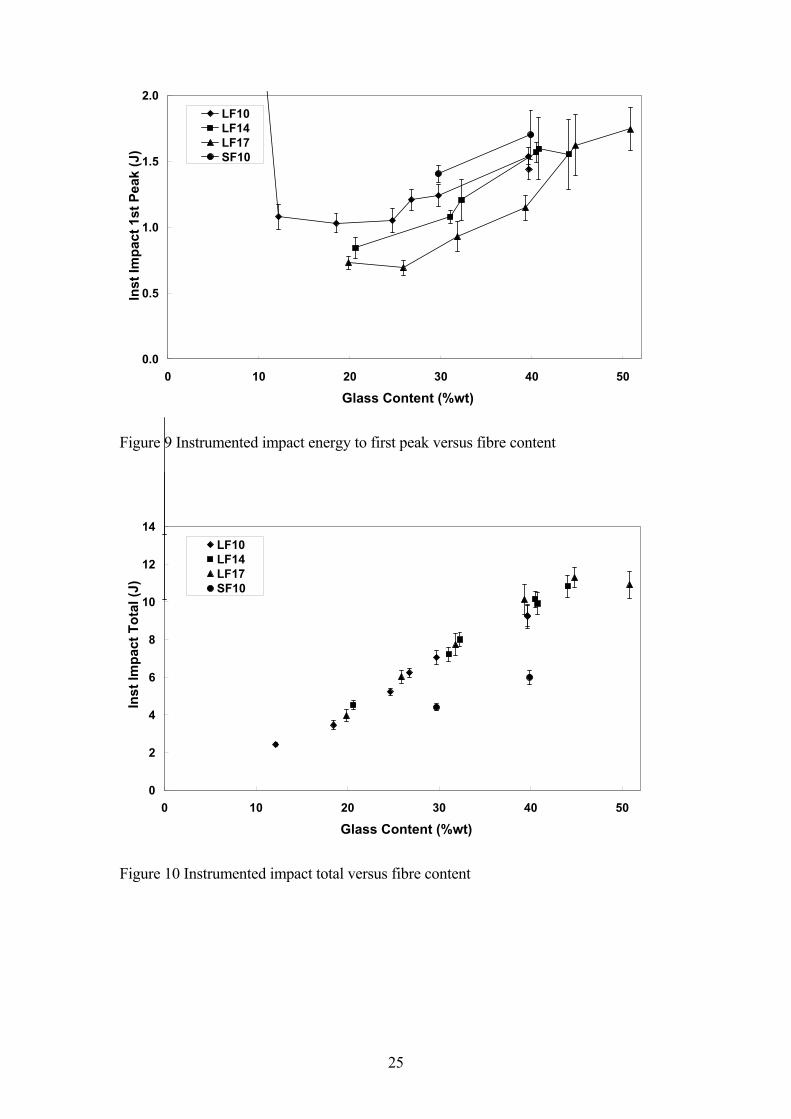
The results of the instrumented impact testing are summarised in Figures 9 and 10.
Figure 9 shows the energy absorbed up to the first peak in the force-time (displacement)
curve, which is equivalent to the energy required to generate a critical flaw in the
material. Figure 10 shows the total energy absorbed by the samples during the complete
test. It is interesting to note the differences in the trends observed in Figures 9 and 10.
The data for the total energy absorbed by the LFPA samples all fall approximately on a
8
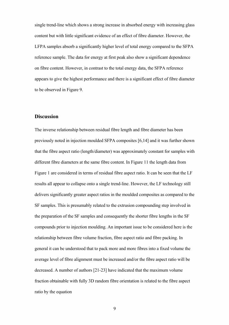
single trend-line which shows a strong increase in absorbed energy with increasing glass
content but with little significant evidence of an effect of fibre diameter. However, the
LFPA samples absorb a significantly higher level of total energy compared to the SFPA
reference sample. The data for energy at first peak also show a significant dependence
on fibre content. However, in contrast to the total energy data, the SFPA reference
appears to give the highest performance and there is a significant effect of fibre diameter
to be observed in Figure 9.
Discussion
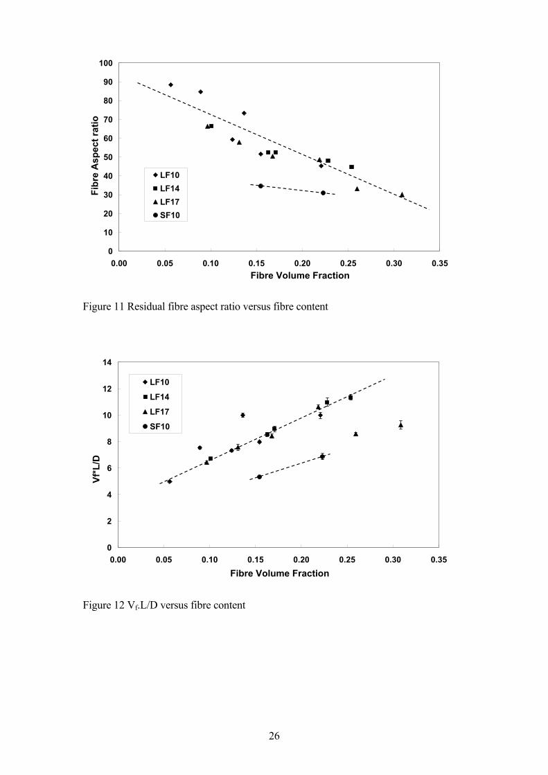
The inverse relationship between residual fibre length and fibre diameter has been
previously noted in injection moulded SFPA composites [6,14] and it was further shown
that the fibre aspect ratio (length/diameter) was approximately constant for samples with
different fibre diameters at the same fibre content. In Figure 11 the length data from
Figure 1 are considered in terms of residual fibre aspect ratio. It can be seen that the LF
results all appear to collapse onto a single trend-line. However, the LF technology still
delivers significantly greater aspect ratios in the moulded composites as compared to the
SF samples. This is presumably related to the extrusion compounding step involved in
the preparation of the SF samples and consequently the shorter fibre lengths in the SF
compounds prior to injection moulding. An important issue to be considered here is the
relationship between fibre volume fraction, fibre aspect ratio and fibre packing. In
general it can be understood that to pack more and more fibres into a fixed volume the
average level of fibre alignment must be increased and/or the fibre aspect ratio will be
decreased. A number of authors [21-23] have indicated that the maximum volume
fraction obtainable with fully 3D random fibre orientation is related to the fibre aspect
ratio by the equation
9
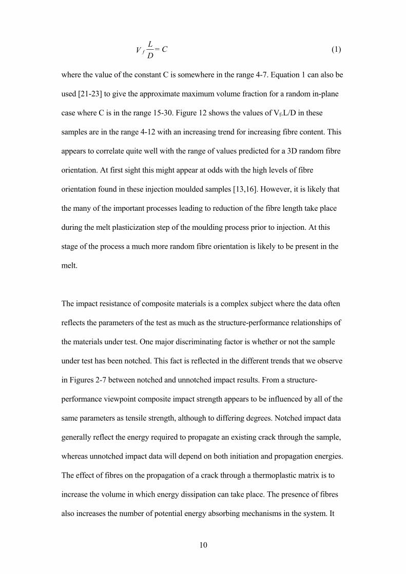
C = D
LV f (1)
where the value of the constant C is somewhere in the range 4-7. Equation 1 can also be
used [21-23] to give the approximate maximum volume fraction for a random in-plane
case where C is in the range 15-30. Figure 12 shows the values of Vf.L/D in these
samples are in the range 4-12 with an increasing trend for increasing fibre content. This
appears to correlate quite well with the range of values predicted for a 3D random fibre
orientation. At first sight this might appear at odds with the high levels of fibre
orientation found in these injection moulded samples [13,16]. However, it is likely that
the many of the important processes leading to reduction of the fibre length take place
during the melt plasticization step of the moulding process prior to injection. At this
stage of the process a much more random fibre orientation is likely to be present in the
melt.
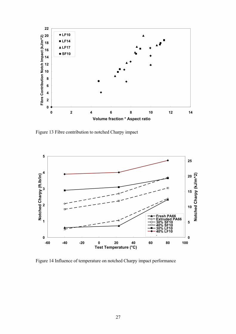
The impact resistance of composite materials is a complex subject where the data often
reflects the parameters of the test as much as the structure-performance relationships of
the materials under test. One major discriminating factor is whether or not the sample
under test has been notched. This fact is reflected in the different trends that we observe
in Figures 2-7 between notched and unnotched impact results. From a structure-
performance viewpoint composite impact strength appears to be influenced by all of the
same parameters as tensile strength, although to differing degrees. Notched impact data
generally reflect the energy required to propagate an existing crack through the sample,
whereas unnotched impact data will depend on both initiation and propagation energies.
The effect of fibres on the propagation of a crack through a thermoplastic matrix is to
increase the volume in which energy dissipation can take place. The presence of fibres
also increases the number of potential energy absorbing mechanisms in the system. It
10
has been proposed that various energy dissipating mechanisms may operate when a
discontinuous fibre reinforced composite fractures from an existing notch [18].
Deformation and fracture of the matrix takes place in an area in front of the crack tip. At
the same time the applied load, transferred by shear to the fibres, may exceed the
strength of the fibre-matrix interface and debonding may occur. Transfer of stress may
still be possible to a debonded fibre via frictional forces along the interface. Fibres may
fracture if the fibre stress level exceeds the local fibre strength. Fibres that have
fractured away from the crack interface will be pulled out of the matrix, which may also
involve energy dissipation. There is still some debate over which, if any, of these
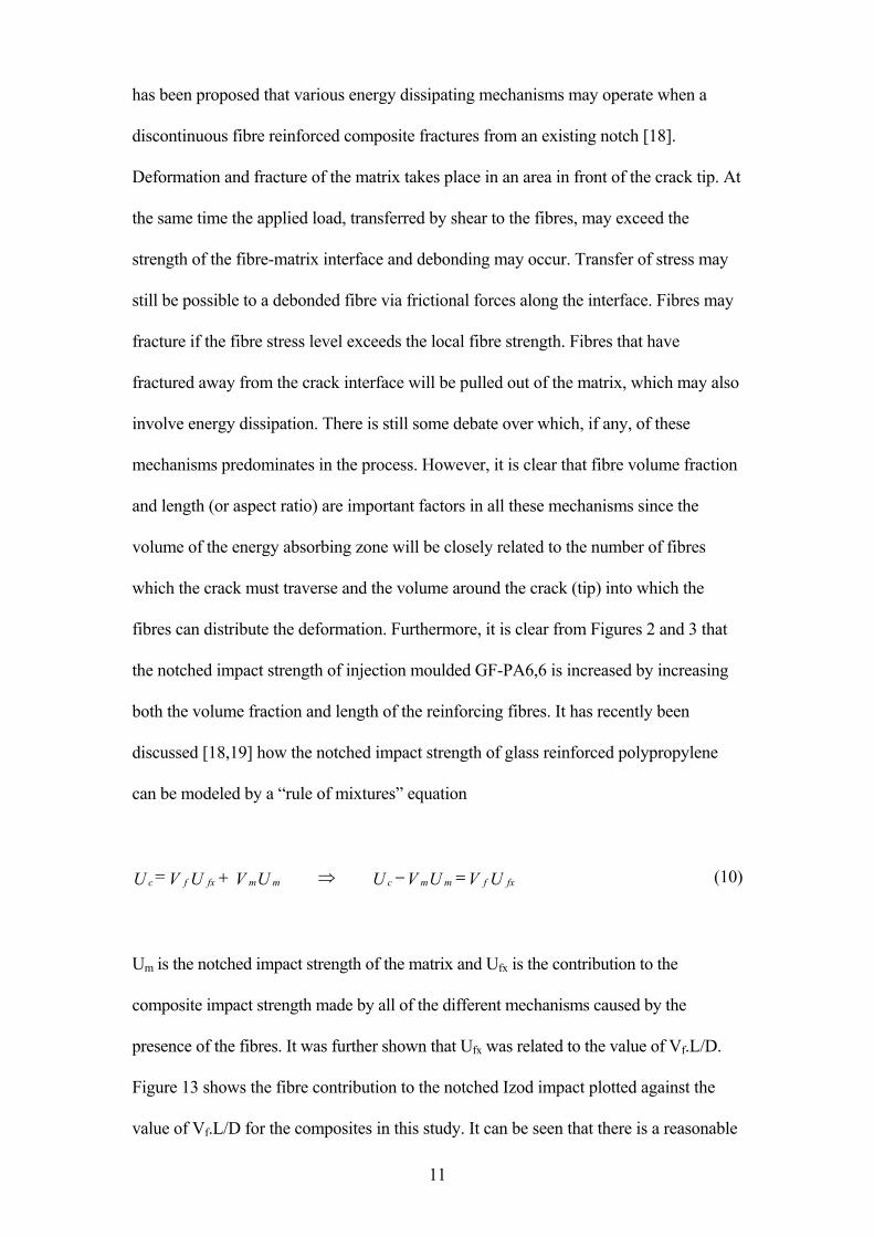
mechanisms predominates in the process. However, it is clear that fibre volume fraction
and length (or aspect ratio) are important factors in all these mechanisms since the
volume of the energy absorbing zone will be closely related to the number of fibres
which the crack must traverse and the volume around the crack (tip) into which the
fibres can distribute the deformation. Furthermore, it is clear from Figures 2 and 3 that
the notched impact strength of injection moulded GF-PA6,6 is increased by increasing
both the volume fraction and length of the reinforcing fibres. It has recently been
discussed [18,19] how the notched impact strength of glass reinforced polypropylene
can be modeled by a �rule of mixtures� equation
UVUV UUV UV = U fxfmmcmmfxfc =−⇒+ (10)
Um is the notched impact strength of the matrix and Ufx is the contribution to the
composite impact strength made by all of the different mechanisms caused by the
presence of the fibres. It was further shown that Ufx was related to the value of Vf.L/D.
Figure 13 shows the fibre contribution to the notched Izod impact plotted against the
value of Vf.L/D for the composites in this study. It can be seen that there is a reasonable
11
level of correlation in Figure 13 and that the results for the LF and SF samples now
appear to fall on the same line. It should be noted that using the notched Charpy results
produces a very similar relationship. Given the outcome of the above discussion on the
likely inverse relationship between L/D and Vf and the maximum value of their product
obtainable depending on the average fibre orientation this suggests that there may exist
an upper boundary on the fibre contribution to the composite notched impact
performance in injection moulded composites.
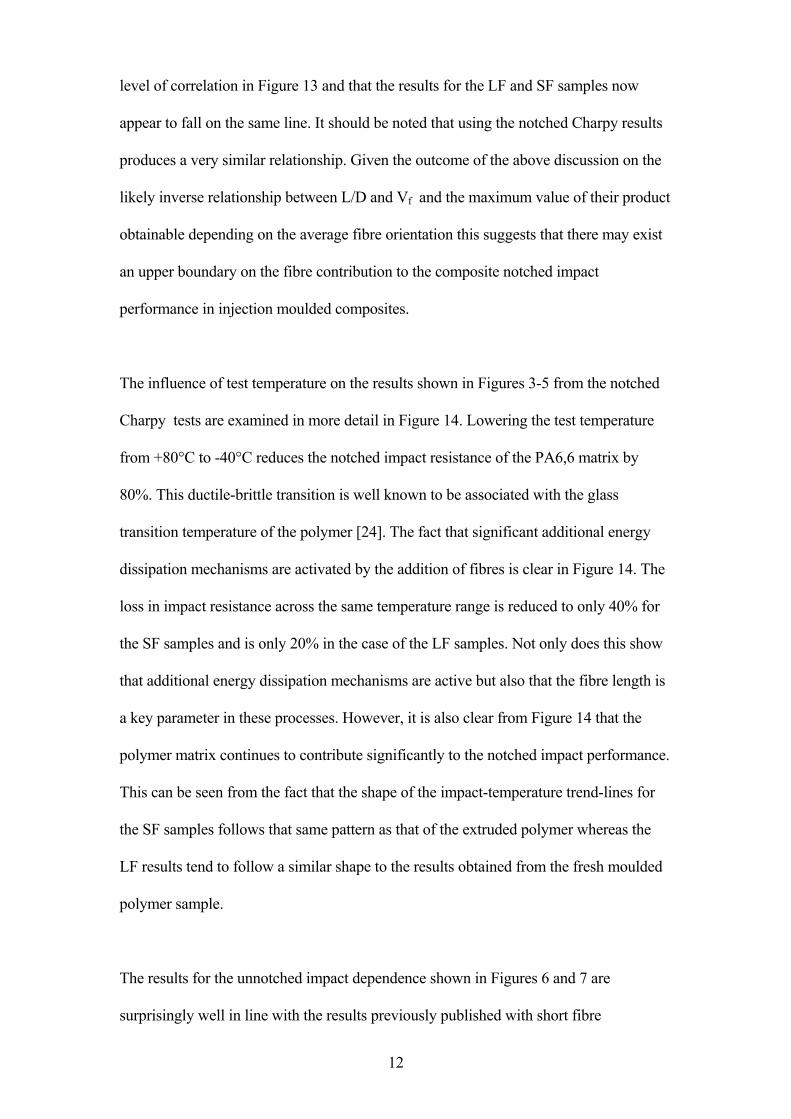
The influence of test temperature on the results shown in Figures 3-5 from the notched
Charpy tests are examined in more detail in Figure 14. Lowering the test temperature
from +80°C to -40°C reduces the notched impact resistance of the PA6,6 matrix by
80%. This ductile-brittle transition is well known to be associated with the glass
transition temperature of the polymer [24]. The fact that significant additional energy
dissipation mechanisms are activated by the addition of fibres is clear in Figure 14. The
loss in impact resistance across the same temperature range is reduced to only 40% for
the SF samples and is only 20% in the case of the LF samples. Not only does this show
that additional energy dissipation mechanisms are active but also that the fibre length is
a key parameter in these processes. However, it is also clear from Figure 14 that the
polymer matrix continues to contribute significantly to the notched impact performance.
This can be seen from the fact that the shape of the impact-temperature trend-lines for
the SF samples follows that same pattern as that of the extruded polymer whereas the
LF results tend to follow a similar shape to the results obtained from the fresh moulded
polymer sample.
The results for the unnotched impact dependence shown in Figures 6 and 7 are
surprisingly well in line with the results previously published with short fibre
12

reinforcement [11-13]. The unnotched impact strength of many thermoplastic polymers
is more than an order of magnitude greater than their notched impact strength. In
general this ratio is significantly reduced by the addition of fillers or fibres. Such
reinforcements can severely reduce the energy required to initiate a critical flaw in the
system while concurrently the presence of fibres can significantly increase the resistance
to crack propagation (as discussed above). It has been shown that fibre-matrix
debonding at the fibre tips can occur well before the failure of a composite under load
[1,2]. These debonded regions can act singly, or at higher strain levels through multiple
interactions, as critical flaws where the size of the flaws can be proportional to the
average fibre diameter. Increasing addition of fibres can also lead to an increase in
unnotched impact by increasing the composite stiffness and therefore the energy
required to achieve the strain levels for such debonding to occur. This notching effect of
fibres already reaches its maximum influence at very low fibre contents of the order of
magnitude of 2-4% wt. [13] Consequently, in the normal range of fibre contents found
in these composites, the resin properties have only a limited influence on the unnotched
impact strength and the composite performance in this type of test is dominated by fibre
and interface effects. Despite the fact that the average fibre length is significantly
greater in these LF composites there are still a very large number of short fibres and
glass particles present in the system due to the significant amount of fibre breakage that
occurs during the injection moulding process. It may well be that the level of short
fibres and particulates (which may become completely debonded at low strain levels) is
still of a sufficiently high level to generate the critical flaw in a LF sample unnotched
impact test at a similar level as obtained in a SF sample.
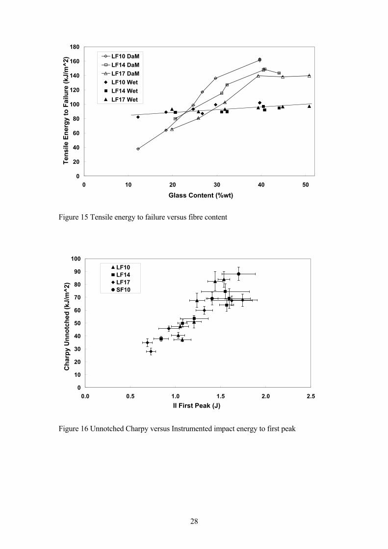
The above discussion relates only to these materials in the dry state. The data in Figure
8 show that boiling water conditioning results in a very different pattern of unnotched
13
impact response. The disappearance of the fibre and interface influence on the
unnotched impact has previously been noted [14,15] in data from similar experiments
on injection moulded SFPA after hydrothermal conditioning in ethylene glycol solution.
The boiling water conditioning has already been shown to significantly reduce the
Young�s modulus, tensile strength and interfacial strength of these composites [16,17].
At the same time increases in the tensile elongation to failure are noted. It is also well
known that the accompanying water absorption lower the glass transition temperature of
the PA6,6 matrix from approximately 70°C in the dry state to well below room
temperature in the conditioned state [24]. For unreinforced PA6,6 this results in a
transition from brittle to ductile failure and a significant increase in the energy
dissipated in impact testing. Although this may not translate directly into composite
performance it is possible that Figure 8 is showing more evidence of a matrix dominated
failure with the reduction in glass transition temperature coupled with the lowering of
the stress transfer capability of the interface. As discussed above the unnotched Charpy
impact performance of these composites is dominated by the energy required to produce
the first critical flaw. Failure of a Charpy specimen is usually initiated through tensile
failure on the back side of the bending specimen. Although pendulum impact testing is
carried out at much higher rates than tensile testing, it is possible to obtain an estimate
of the energy required to break a specimen in a tensile test from a combination of the
tensile strength and elongation to failure. Figure 15 shows data from such an analysis
plotted versus fibre content for both DaM and boiling water conditioned samples. It can
be seen that this analysis reproduces the trends shown in Figures 7 and 8 quite
accurately. The DaM samples show a strong dependence on fibre content and fibre
diameter, whereas the conditioned samples show little dependence on either parameter
and an approximately constant value in the middle of the DaM range.
It was previously noted that there appeared to be similarities between trends observed in
the instrumented impact results and those obtained in the pendulum impact tests. These
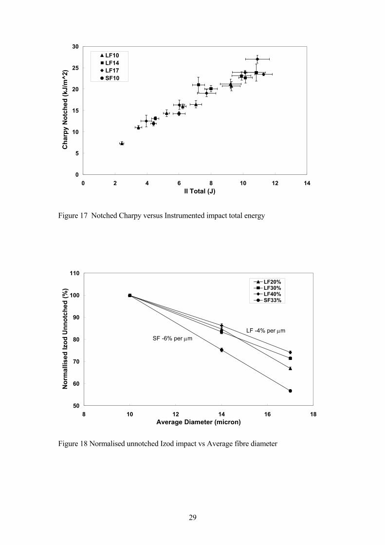
similarities are further examined in Figures 16 and 17. Figure 16 compares the results
for unnotched Charpy with the instrumented impact energy to peak load. Whereas
Figure 17 compares the notched Charpy results with the instrumented impact total
energy. It can be seen that a significant correlation is observed in both the Figures. This
14
observation further supports the hypothesis that the unnotched pendulum impact
performance of glass-fibre reinforced polyamide is related mainly to the generation of
the first critical flaw in the system. In a previous study [12] of the influence of fibre
diameter on the mechanical performance of injection moulded short fibre reinforced
PA6,6 a loss of unnotched impact of approximately -6% per 1 μm increase in average
fibre diameter in the range of 10-17 μm was reported. In Figure 18 the data from these
LF samples are examined in a similar manner. The figure shows the diameter
dependence of the unnotched Izod impact performance from the LF samples at three
fixed fibre contents normalised to the performance level for the 10 μm diameter
samples. The data is compared with a previously published study of injection moulded
SFPA at 33% fibre content. It is clear from this figure that the LF samples exhibit a very
similar unnotched impact inverse dependence on average fibre diameter as previously
observed with SF samples although the increased fibre length has mitigated the
sensitivity on fibre diameter to some extent with an average slope in Figure 18 of -4%
per 1 μm increase in fibre diameter.
Conclusions
This study of injection moulded long glass-fibre reinforced polyamide 6,6 composites
has revealed that the average residual fibre length of all LFPA samples exhibited an
inverse dependence on fibre content at fixed fibre diameter and a strong dependence on
the average fibre diameter at fixed fibre content. These dependencies resulted in an
invariable residual fibre aspect ratio for long fibre samples prepared with the same fibre
content and different fibre diameters. The product of the residual fibre aspect ratio and
the fibre volume fraction fell in the range of 4-12 indicative of the fibre aspect ratio
being limited by a maximum packing fraction of fibres with a 3D random fibre
15
orientation at some point during the melt processing. The fibre length and content did
have a significant effect on composite notched impact but fibre diameter did not. Fibre
diameter and content did have a significant effect on composite unnotched impact but
fibre length did not. In instrumented multiaxial impact testing the total energy value
followed similar trends to notched impact, the energy to first peak followed the same
trends as unnotched impact. Unnotched impact performance of these composites lost all
dependence of fibre content, length and diameter after boiling water conditioning.
Analysis of the notched impact data provided more evidence that fibre packing
considerations in injection moulded thermoplastics results in an upper limit to the value
of the product of the fibre volume fraction and aspect ratio, resulting in some kind of
upper boundary on the fibre contribution to the composite notched impact performance.
The LFPA samples exhibited a very similar unnotched impact dependence on average
fibre diameter as previously observed with SFPA samples.
Acknowledgement
The author gratefully acknowledges the support of Owens Corning Science and
Technology with the preparation and testing of the materials used in this study.
16
References
1. Sato N, Kurauchi T, Sato S, and Kamigaito O. Mechanism of fracture of short glass
fibre-reinforced polyamide thermoplastic. J. Mater. Sci. 1984:19;1145-1152
2. Sato N, Kurauchi T, Sato S, and Kamigaito O. Reinforcing mechanism by small
diameter fiber in short fiber composites. J. Compos. Mater. 1998:22;850-873
3. Horst JJ, and Spoormaker JL. Fatigue fracture mechanisms and fractography of
short-glass fibre-reinforced polyamide 6. J. Mater. Sci. 1997:32;3641-3651.
4. Akay M, Barkley D. Fibre orientation and mechanical behaviour in reinforced
thermoplastic injection mouldings. J.Mater. Sci. 1991;26:2731-42
5. Laura DM, Keskkula H, Barlow JW, Paul DR. Effect of glass fiber surface
chemistry on the properties of glass fiber reinforced, rubber-toughened nylon 6.
Polymer 2002:43;4673-4687
6. Thomason JL. The influence of fibre properties of the performance of glass-fibre-
reinforced polyamide 6,6. Comp. Sci. Tech. 1999;59:2315-2328.
7. Hassan A, Yahya R, Yahaya AH, Tahir ARM, Hornsby PR. Tensile, Impact and
Fiber Length Properties of Injection-molded Short and Long Glass Fiber-reinforced
Polyamide 6,6 Composites. J.Reinforced Plastics and Composites 2004;23:969-986.
8. Carlson E, Nelson K. Nylon under the hood: history of innovation. Automotive
Engineering 1996;104:84-89.
9. Guyot H. VERTON in Long Fibres. Plast. Mod. Elastom. 1985;37(5):44-45.
10. Toll S, Aronsson C-G. Notched Strength of Long- and Short-Fibre Reinforced
Polyamide. Comp. Sci. Tech. 1992;46:43-54.
11. Belbin GR, Staniland PA. Advanced Thermoplastics and their Composites.
Philosophical Transactions of the Royal Society of London. Series A, Mathematical
and Physical Sciences. 1987;322:451-464.
17

12. Bailey RS, Davies M, Moore DR. Processing property characteristics for long glass
fibre reinforced polyamide. Composites 1989;20:453-460.
13. Thomason JL. Structure-property relationships in glass reinforced polyamide: 1)
The effect of fibre content. Polym.Composites 2006;27:552-562.
14. Thomason JL. Structure-property relationships in glass reinforced polyamide: 2)
The effects of average fibre diameter and diameter distribution. Polym.Composites
2007;27:331-343.
15. Thomason JL. Structure-property relationships in glass reinforced polyamide: 3)
Effects of hydrolysis ageing on the dimensional stability and performance of short
glass-fibre reinforced Polyamide 66. Polym.Composites 2007;27:344-354.
16. Thomason JL. The influence of fibre length, diameter and concentration on the
modulus of glass-fibre reinforced polyamide 6,6. Compos A 2008;39:1732-1738.
17. Thomason JL. The influence of fibre length, diameter and concentration on the
strength and strain to failure of glass-fibre reinforced polyamide 6,6. Compos A
2008;39:1618-1624.
18. Thomason JL and Vlug MA. The influence of fibre length and concentration on the
properties of glass fibre reinforced polypropylene: 4) Impact Properties. Composites
1996;28A:277-288.
19. Thomason J.L. The influence of fibre length and concentration on the properties of
glass fibre reinforced polypropylene: 5) Injection moulded long and short fibre PP�,
Compos A 2002;33:1641-1652.
20. Williams JCL, Watson SJ and Boydell P. Factors affecting the properties of Nylons.
In: Kohan MI, editor. Nylon Plastics Handbook. Munich: Hanser, 1995. p.294.
21. Gibson AG and Payne DJ. Flexural and impact strength improvement in injected
moulded SMC. Composites 1989;20:151-158.
18

22. Evans KE and Gibson AG. Prediction of the maximum packing fraction achievable
in randomly oriented short-fibre composites. Compos.Sci.Technol. 1986;25:149-
162.
23. Toll S, Ericson A, Zuber A. and Manson JE. Packing of discontinuous fibres.
Proceedings of ICCM-9, Vol III, 391-397, Woodhead Publishing Limited,
Cambridge, UK 1993,
24. Keskkula H and Paul DR. Toughened Nylons In: Kohan MI, editor. Nylon Plastics
Handbook. Munich: Hanser, 1995. p.414-430.
19
List of Figures
Figure 1 Residual weight average fibre length versus fibre content
Figure 2 Notched Izod impact versus fibre content
Figure 3 Notched Charpy impact versus fibre content
Figure 4 -40°C Notched Charpy impact versus fibre content
Figure 5 +80°C Notched Charpy impact versus fibre content
Figure 6 Unnotched Izod impact versus fibre content
Figure 7 Unnotched Charpy impact versus fibre content
Figure 8 Unnotched Charpy impact after 24 hour boil versus fibre content
Figure 9 Instrumented impact energy to first peak versus fibre content
Figure 10 Instrumented impact total versus fibre content
Figure 11 Residual fibre aspect ratio versus fibre content
Figure 12 Vf.L/D versus fibre content
Figure 13 Fibre contribution to notched Charpy impact
Figure 14 Influence of temperature on notched Charpy impact performance
Figure 15 Tensile energy to failure versus fibre content
Figure 16 Unnotched Charpy versus Instrumented impact energy to first peak
Figure 17 Notched Charpy versus Instrumented impact total energy
Figure 18 Normalised unnotched Izod impact vs Average fibre diameter
20
y = -0.02x + 1.11
R2 = 0.83
y = -0.02x + 1.50
R2 = 0.95
0.2
0.4
0.6
0.8
1.0
1.2
0 10 20 30 40 50
Glass Content (%wt)
Wt
Av
era
ge F
ibre
Le
ng
th (
mm
)
LF10
LF14
LF17
SF10
Figure 1 Residual weight average fibre length versus fibre content
0
1
2
3
4
5
0 10 20 30 40 50
Glass Content (%wt)
Izo
d N
otc
he
d (
ft.l
b/i
n)
0
5
10
15
20
25
Izo
d N
otc
hed
(kJ/m
^2)
LF10LF14LF17SF10.
fresh
extruded
Figure 2 Notched Izod impact versus fibre content
21
0
1
2
3
4
5
6
0 10 20 30 40 50
Glass Content (%wt)
Ch
arp
y n
otc
hed
(ft
.lb
/in
)
0
5
10
15
20
25
30
Ch
arp
y n
otc
hed
(kJ
/m^
2)
LF10LF14LF17SF10.
extruded
fresh
Figure 3 Notched Charpy impact versus fibre content
0
1
2
3
4
5
6
0 10 20 30 40 50
Glass Content (%wt)
-40
°C C
harp
y N
otc
he
d (
ft.lb
/in
)
0
5
10
15
20
25
30
-40°C
Ch
arp
y N
otc
he
d (
kJ/m
^2)
LF10LF14LF17SF10.
Figure 4 -40°C Notched Charpy impact versus fibre content
22
0
1
2
3
4
5
6
0 10 20 30 40 50
Glass Content (%wt)
80°C
Ch
arp
y N
otc
hed
(ft
.lb
/in
)
0
5
10
15
20
25
30
80
°C C
harp
y N
otc
hed
(kJ
/m^
2)
LF10LF14LF17SF10
Figure 5 +80°C Notched Charpy impact versus fibre content
0
5
10
15
20
25
30
35
0 10 20 30 40 50
Glass Content (%wt)
Izo
d U
nn
otc
hed
(ft
.lb
/in
)
0
25
50
75
100
125
Izo
d U
nn
otc
he
d (
kJ/m
^2)
LF10LF14LF17SF10.
Figure 6 Unnotched Izod impact versus fibre content
23

0
5
10
15
20
25
0 10 20 30 40 50
Glass Content (%wt)
Ch
arp
y U
nn
otc
he
d (
ft.lb
/in
)
0
20
40
60
80
100
Ch
arp
y U
nn
otc
he
d (
kJ/m
^2)
LF10LF14LF17SF10.
Figure 7 Unnotched Charpy impact versus fibre content
0
5
10
15
20
25
30
0 10 20 30 40 50
Glass Content (%wt)
Ch
arp
y U
nn
otc
hed
(ft
.lb
/in
)
0
20
40
60
80
100
120
Ch
arp
y U
nn
otc
hed
(k
J/m
^2
)
LF10LF14LF17SF10
Figure 8 Unnotched Charpy impact after 24 hour boil versus fibre content
24
0.0
0.5
1.0
1.5
2.0
0 10 20 30 40 50
Glass Content (%wt)
Inst
Imp
act
1st
Peak
(J)
LF10
LF14
LF17
SF10
Figure 9 Instrumented impact energy to first peak versus fibre content
0
2
4
6
8
10
12
14
0 10 20 30 40 50
Glass Content (%wt)
Inst
Imp
act
To
tal (J
)
LF10
LF14
LF17
SF10
Figure 10 Instrumented impact total versus fibre content
25
0
10
20
30
40
50
60
70
80
90
100
0.00 0.05 0.10 0.15 0.20 0.25 0.30 0.35
Fibre Volume Fraction
Fib
re A
sp
ect
rati
o
LF10
LF14
LF17
SF10
Figure 11 Residual fibre aspect ratio versus fibre content
0
2
4
6
8
10
12
14
0.00 0.05 0.10 0.15 0.20 0.25 0.30 0.35
Fibre Volume Fraction
Vf*
L/D
LF10
LF14
LF17
SF10
Figure 12 Vf.L/D versus fibre content
26
0
2
4
6
8
10
12
14
16
18
20
22
0 2 4 6 8 10 12 14
Volume fraction * Aspect ratio
Fib
re C
on
trib
uti
on
No
tch
Im
pact
(kJ/m
^2) LF10
LF14
LF17
SF10
Figure 13 Fibre contribution to notched Charpy impact
0
1
2
3
4
5
-60 -40 -20 0 20 40 60 80 100
Test Temperature (°C)
No
tch
ed
Ch
arp
y (
ft.lb
/in
)
0
5
10
15
20
25
No
tch
ed
Ch
arp
y (
kJ/m
^2)
Fresh PA66Extruded PA6630% SF1040% SF1030% LF1040% LF10.
Figure 14 Influence of temperature on notched Charpy impact performance
27
0
20
40
60
80
100
120
140
160
180
0 10 20 30 40 50
Glass Content (%wt)
Te
nsile
En
erg
y t
o F
ailu
re (
kJ/m
^2) LF10 DaM
LF14 DaM
LF17 DaM
LF10 Wet
LF14 Wet
LF17 Wet
Figure 15 Tensile energy to failure versus fibre content
0
10
20
30
40
50
60
70
80
90
100
0.0 0.5 1.0 1.5 2.0 2.5
II First Peak (J)
Ch
arp
y U
nn
otc
hed
(kJ
/m^
2)
LF10
LF14
LF17
SF10
Figure 16 Unnotched Charpy versus Instrumented impact energy to first peak
28
0
5
10
15
20
25
30
0 2 4 6 8 10 12 14
II Total (J)
Ch
arp
y N
otc
he
d (
kJ/m
^2)
LF10
LF14
LF17
SF10
Figure 17 Notched Charpy versus Instrumented impact total energy
50
60
70
80
90
100
110
8 10 12 14 16 1
Average Diameter (micron)
No
rmall
ised
Izo
d U
nn
otc
hed
(%
)
8
LF20%LF30%LF40%SF33%
SF -6% per μm
LF -4% per μm
Figure 18 Normalised unnotched Izod impact vs Average fibre diameter
29