Embed Size (px)
Citation preview
To
La
b
a
ARR2AA
KMFEA
1
lfdt(sTvaencce
tqa
S2
u(
0d
Journal of Materials Processing Technology 212 (2012) 1169–1176
Contents lists available at SciVerse ScienceDirect
Journal of Materials Processing Technology
journa l homepage: www.e lsev ier .com/ locate / jmatprotec
he influence of the processing parameters on the formation of iron thin filmsn alumina balls by mechanical coating technique
iang Haoa, Yun Lub,∗, Hiroshi Asanumab, Jie Guoa
Graduate school, Chiba University, 1-33, Yayoi-cho, Inage-ku, Chiba, 263-8522, JapanGraduate School & Faculty of Engineering, Chiba University, 1-33, Yayoi-cho, Inage-ku, Chiba, 263-8522, Japan
r t i c l e i n f o
rticle history:eceived 30 May 2011eceived in revised form3 December 2011ccepted 1 January 2012
a b s t r a c t
Mechanical coating technique (MCT) was used to fabricate Fe thin films on alumina balls. The influence ofthe processing parameters including the milling atmosphere and the rotation speed of planetary ball millon the formation of the thin films was investigated. The results of SEM and EDS showed that Fe particlesreacted with oxygen in the air atmosphere and the formed ferroferric oxide hindered the formation of thethin films. Rotation speed also had great influence. Continuous Fe thin films with an average thickness of
vailable online 11 January 2012eywords:echanical coating technique
e thin filmvolution model
about 10 �m were formed during the milling operation at 300 rpm. However, they could not be formed at200 and 400 rpm. Furthermore, the evolution of the thin films was also studied and analyzed. An evolutionmodel was proposed to describe it. According to the model, the evolution fell into nucleation, growth ofnuclei, formation of thin films and exfoliation. It was considered that mechanical interlocking played animportant role in the formation of the thin films.
dhesion
. Introduction
Over the recent years, energy shortage and environmental pol-ution are becoming increasingly severe. The investigation on theabrication and functional characteristics of TiO2 thin films hasrawn special attention due to their potential applications in pho-ocatalysis by Maria et al. (2011) and by Onoda and Yoshikawa2008), solar cells by Zheng et al. (2011) and Singh et al. (2004), sen-ors by Mohammadi and Fray (2007) and by György et al. (2005).ill now, a variety of techniques including sol–gel method, chemicalapor deposition, electrodeposition, molecular beam epitaxy anderosol pyrolysis have been used to prepare TiO2 thin films (Senthilt al., 2010). However, there are some drawbacks in these tech-iques, such as expensive equipments, complicated processes, highost, and low performance, among others. To overcome these short-omings, a novel technique to prepare TiO2 thin films is urgentlyxpected.
The mechanical alloying (MA), developed in 1966, can be used
o fabricate a variety of advanced materials including amorphous,uasicrystals, nanocrystalline materials and composite materialss well as the materials which are difficult or impossible to be∗ Corresponding author at: Department of Mechanical and Engineering, Graduatechool & Faculty of Engineering, Chiba University, 1-33, Yayoi-cho, Inage-ku, Chiba63-8522, Japan. Tel.: +81 43 290 3514; fax: +81 43 290 3039.
E-mail addresses: [email protected] (L. Hao), [email protected] (Y. Lu), [email protected] (H. Asanuma), [email protected]. Guo).
924-0136/$ – see front matter © 2012 Elsevier B.V. All rights reserved.oi:10.1016/j.jmatprotec.2012.01.001
© 2012 Elsevier B.V. All rights reserved.
obtained by conventional melting and casting technique summa-rized by Suryanarayana (2001). Despite many advantages, someinevitable problems such as the contamination of powder fromgrinding medium or the contamination of grinding medium frompowder are still irresolvable. In many cases, it is found that con-tamination is difficult to be eliminated.
Ball milling, which is well known for mechanical alloying, hasbeen found its application for mechanical coating. Mechanicalcoating technique (MCT) has been successfully used to fabricateTiO2/metal composite photocatalyst films in the previous study ofLu et al. (2005). In their early study, it was found that the direct coat-ing of TiO2 powder on Al2O3 balls by ball milling was very difficult.However, the coating of metal powder on Al2O3 balls was very easy.Therefore, they firstly coated Al2O3 balls with metal powder by ballmilling to form metal films and afterwards deposited TiO2 powderon the metal films by the same method. Finally, TiO2/metal com-posite photocatalyst films were prepared and they presented highphotocatalytic activity (Lu et al., 2011). In fact, MCT is a technique orprocess to fabricate metal thin films or TiO2/metal composite pho-tocatalyst films by ball milling. According to the effect of chargeseparation (Nosaka et al., 1984), metals with higher work functionshould show higher charge separation efficiency. The increase ofcharge separation efficiency can improve photocatalytic activity ofTiO2. Therefore, different metals were used to prepare TiO2/metal
composite photocatalyst films to increase photocatalytic activity ofTiO2.Although there are large numbers of papers on the process mod-eling of MA by Budin et al. (2009) and Harris et al. (2001), the
1170 L. Hao et al. / Journal of Materials Processing Technology 212 (2012) 1169–1176
tic diagram of MCT.
iioaatso
tistp
2
aeommwsptrmp23to
bafs
Al2O3Fe
58 h
8 h
20 hIn
ten
sity
(a.
u.)
26 h
40 60 800 h
2 Theta (degree)
TS
Fig. 1. Schema
nvestigation about the evolution of metal films or coatings dur-ng ball milling is scarce. Kobayashi (1995) formed metal thin filmsn the ceramic milling balls during ball milling. Kim et al. (2003)lso coated wax onto copper powder by ball milling. Besides, Songnd Srolovitz (2006) studied the contamination in mechanical con-acts from the point of material transfer by molecular dynamicsimulation. However, these works have not revealed the evolutionf metal films during ball milling.
In this work MCT was used to prepare iron (Fe) thin films onhe surfaces of alumina (Al2O3) balls. The influence of the process-ng parameters including the milling atmosphere and the rotationpeed on the formation of the thin films was studied. Furthermore,he evolution of the thin films was also studied and a model wasroposed to describe it.
. Experimental
Fe powder and Al2O3 balls were used as the coating materialnd the substrates with related parameters listed in Table 1. Plan-tary ball mill (type: P5/4, Fritsch) was employed in the millingperation. The schematic diagram of MCT and the planetary ballill can be seen in Fig. 1. The source materials were put in the potade of Al2O3 with a volume of 250 mL and the milling operationas carried out for 4, 8, 12, 16, 20, 24, 26, 32, 40 and 58 h from the
tart of the milling operation. Before the desired sample was com-leted, the pot was not opened. That means the pot was closed allhe time during the milling operation, even for 58-h sample. Theotation speeds were fixed at 200, 300 and 400 rpm (revolutions perinute). To investigate the influence of the milling atmosphere, the
ot was opened for 2 min when milling time came to 4, 8, 12, 16,0, 24, 26, 32, 40 and 58 h during the contrast milling operation at00 rpm. For example, during the preparation of the 20-h sample,he pot was opened for 2 min after 4, 8, 12 and 16 h from the startf milling operation.
The chemical content of the Fe-coated Al2O3 balls was examined
y XRD (JEOL JDX-3530). Cu-K� radiation in the condition of 30 kVnd 20 mA was adopted. The samples of the Fe-coated Al2O3 ballsor XRD were prepared as follows: a piece of glass with the dimen-ion of 40 mm × 50 mm × 2 mm was used as the holder. Then, theable 1ource materials loaded into the mill for one coating procedure.
Source materials Weight (g) Average diam
Fe powder 35 0.035Al2O3 balls 30 1
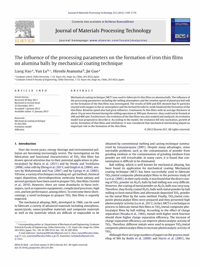
Fig. 2. XRD patterns of the Fe-coated Al2O3 balls after the milling operation at300 rpm for different milling time.
double-sided adhesive tape with the dimension of 17 mm × 26 mmwas stuck on the centre area of the glass holder. Finally, the sam-ples of the Al2O3 balls were laid and stuck on the tape as densely aspossible. The surfaces and the cross sections of the Fe-coated Al2O3balls were characterized by SEM (JEOL JSM-6510). The oxygen con-tent in the surface layer of Fe coatings on Al2O3 balls was measuredin SEM by EDS.
3. Results and discussion
3.1. Formation of Fe thin films
The XRD patterns of the Fe-coated Al2O3 balls after the millingoperation at 300 rpm for different milling time are shown in Fig. 2.The diffraction peaks of Fe appeared when the milling time was8 h and became higher as milling time increased. When it came to26 h, the peaks of Fe reached their peak heights and those of Al2O3
became their lowest ones. Layers of iron might be formed on Al2O3balls. With further increase of milling time to 58 h, the diffractionpeaks of Fe became weaker while those of Al2O3 became stronger.eter (mm) Purity (%) Manufacturer
98.5 Powdertech93.0 Nikkato
L. Hao et al. / Journal of Materials Processing Technology 212 (2012) 1169–1176 1171
F n at 300 rpm for different milling time: (a) 8 h, (b) 20 h, (c) 26 h, (d) 32 h, (e) 40 h and (f)5
It
mawpciptttt
AFitwt
80
100
300 rpm
200 rpm
40
60
400 rpm
0
20
Cover
age
of
the
surf
ace
wit
h F
e (%
)
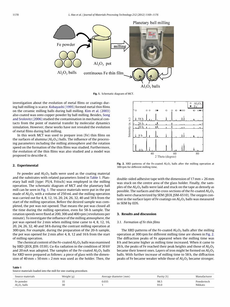
ig. 3. SEM images of the Fe-coated Al2O3 balls’ surfaces after the milling operatio8 h.
t indicates that the layers of iron might be destroyed and parts ofhe layers peeled off.
The SEM images of the Fe-coated Al2O3 balls’ surfaces after theilling operation at 300 pm are also given in Fig. 3. The dark gray
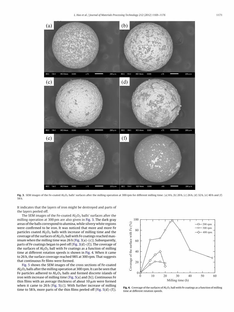
reas of the balls correspond to alumina, while silvery white regionsere confirmed to be iron. It was noticed that more and more Fearticles coated Al2O3 balls with increase of milling time and theoverage of the surfaces of Al2O3 ball with Fe coatings reached max-mum when the milling time was 26 h (Fig. 3(a)–(c)). Subsequently,arts of Fe coatings began to peel off (Fig. 3(d)–(f)). The coverage ofhe surfaces of Al2O3 ball with Fe coatings as a function of millingime at different rotation speeds is shown in Fig. 4. When it cameo 26 h, the surface coverage reached 98% at 300 rpm. That suggestshat continuous Fe films were formed.
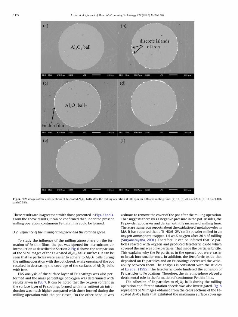
Fig. 5 shows the SEM images of the cross sections of Fe-coatedl2O3 balls after the milling operation at 300 rpm. It can be seen thate particles adhered to Al2O3 balls and formed discrete islands of
ron with increase of milling time (Fig. 5(a) and (b)). Continuous Fehin films with an average thickness of about 10 �m were formedhen it came to 26 h (Fig. 5(c)). With further increase of millingime to 58 h, more parts of the thin films peeled off (Fig. 5(d)–(f)).
0 10 20 30 40 50 60
Milling time (h)
Fig. 4. Coverage of the surfaces of Al2O3 ball with Fe coatings as a function of millingtime at different rotation speeds.
1172 L. Hao et al. / Journal of Materials Processing Technology 212 (2012) 1169–1176
F perata
TFm
3
miostrw
frtdm
ig. 5. SEM images of the cross sections of Fe-coated Al2O3 balls after the milling ond (f) 58 h.
hese results are in agreement with those presented in Figs. 2 and 3.rom the above results, it can be confirmed that under the presentilling operation, continuous Fe thin films could be formed.
.2. Influence of the milling atmosphere and the rotation speed
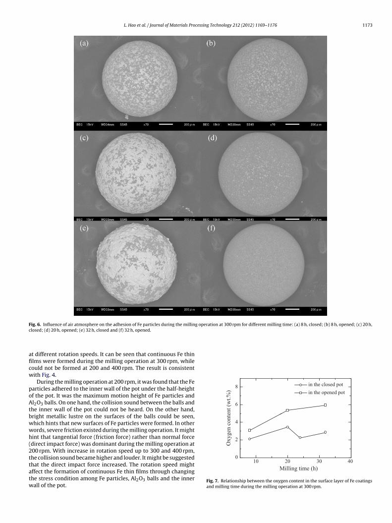
To study the influence of the milling atmosphere on the for-ation of Fe thin films, the pot was opened for intermittent air
ntroduction as described in Section 2. Fig. 6 shows the comparisonf the SEM images of the Fe-coated Al2O3 balls’ surfaces. It can beeen that Fe particles were easier to adhere to Al2O3 balls duringhe milling operation with the pot closed; while opening of the potesulted in decreasing the coverage of the surfaces of Al2O3 ballsith iron.
EDS analysis of the surface layer of Fe coatings was also per-ormed and the mass percentage of oxygen was determined with
esults given in Fig. 7. It can be noted that the oxygen content inhe surface layer of Fe coatings formed with intermittent air intro-uction was much higher compared with those formed during theilling operation with the pot closed. On the other hand, it wasion at 300 rpm for different milling time: (a) 8 h, (b) 20 h, (c) 26 h, (d) 32 h, (e) 40 h
arduous to remove the cover of the pot after the milling operation.That suggests there was a negative pressure in the pot. Besides, theFe powder got darker and darker with the increase of milling time.There are numerous reports about the oxidation of metal powder inMA. It has reported that a Ti–48Al–2W (at.%) powder milled in anoxygen atmosphere trapped 1.5 wt.% oxygen after 20 h of milling(Suryanarayana, 2001). Therefore, it can be inferred that Fe par-ticles reacted with oxygen and produced ferroferric oxide whichcovered the surfaces of Fe particles. That made the particles brittle.This explains why the Fe particles in the opened pot were easierto break into smaller ones. In addition, the ferroferric oxide thatdeposited on Fe particles and on Fe coatings decreased the weld-ability between them. The analysis is consistent with the studiesof Lü et al. (1995). The ferroferric oxide hindered the adhesion ofFe particles to Fe coatings. Therefore, the air atmosphere played adetrimental role in the formation of continuous Fe thin films.
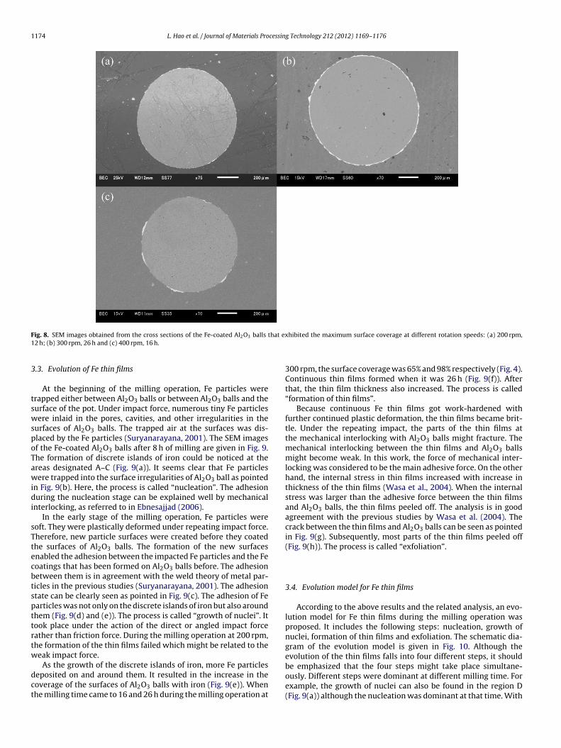
The adhesion of Fe particles to Al2O3 balls during the millingoperation at different rotation speeds was also investigated. Fig. 8represents SEM images obtained from the cross sections of the Fe-coated Al2O3 balls that exhibited the maximum surface coverage
L. Hao et al. / Journal of Materials Processing Technology 212 (2012) 1169–1176 1173
Fig. 6. Influence of air atmosphere on the adhesion of Fe particles during the milling operation at 300 rpm for different milling time: (a) 8 h, closed; (b) 8 h, opened; (c) 20 h,c
aficw
poAtbwwh(2ttatw
6
8 in the closed pot
in the opened pot
2
4
Oxygen
conte
nt
(wt.
%)
10 20 30 400
losed; (d) 20 h, opened; (e) 32 h, closed and (f) 32 h, opened.
t different rotation speeds. It can be seen that continuous Fe thinlms were formed during the milling operation at 300 rpm, whileould not be formed at 200 and 400 rpm. The result is consistentith Fig. 4.
During the milling operation at 200 rpm, it was found that the Fearticles adhered to the inner wall of the pot under the half-heightf the pot. It was the maximum motion height of Fe particles andl2O3 balls. On one hand, the collision sound between the balls and
he inner wall of the pot could not be heard. On the other hand,right metallic lustre on the surfaces of the balls could be seen,hich hints that new surfaces of Fe particles were formed. In otherords, severe friction existed during the milling operation. It mightint that tangential force (friction force) rather than normal forcedirect impact force) was dominant during the milling operation at00 rpm. With increase in rotation speed up to 300 and 400 rpm,he collision sound became higher and louder. It might be suggested
hat the direct impact force increased. The rotation speed mightffect the formation of continuous Fe thin films through changinghe stress condition among Fe particles, Al2O3 balls and the innerall of the pot.Milling time (h)
Fig. 7. Relationship between the oxygen content in the surface layer of Fe coatingsand milling time during the milling operation at 300 rpm.
1174 L. Hao et al. / Journal of Materials Processing Technology 212 (2012) 1169–1176
F that ex1
3
tswspoTawidi
sTtecbtspttrtw
dct
ig. 8. SEM images obtained from the cross sections of the Fe-coated Al2O3 balls2 h; (b) 300 rpm, 26 h and (c) 400 rpm, 16 h.
.3. Evolution of Fe thin films
At the beginning of the milling operation, Fe particles wererapped either between Al2O3 balls or between Al2O3 balls and theurface of the pot. Under impact force, numerous tiny Fe particlesere inlaid in the pores, cavities, and other irregularities in the
urfaces of Al2O3 balls. The trapped air at the surfaces was dis-laced by the Fe particles (Suryanarayana, 2001). The SEM imagesf the Fe-coated Al2O3 balls after 8 h of milling are given in Fig. 9.he formation of discrete islands of iron could be noticed at thereas designated A–C (Fig. 9(a)). It seems clear that Fe particlesere trapped into the surface irregularities of Al2O3 ball as pointed
n Fig. 9(b). Here, the process is called “nucleation”. The adhesionuring the nucleation stage can be explained well by mechanical
nterlocking, as referred to in Ebnesajjad (2006).In the early stage of the milling operation, Fe particles were
oft. They were plastically deformed under repeating impact force.herefore, new particle surfaces were created before they coatedhe surfaces of Al2O3 balls. The formation of the new surfacesnabled the adhesion between the impacted Fe particles and the Feoatings that has been formed on Al2O3 balls before. The adhesionetween them is in agreement with the weld theory of metal par-icles in the previous studies (Suryanarayana, 2001). The adhesiontate can be clearly seen as pointed in Fig. 9(c). The adhesion of Fearticles was not only on the discrete islands of iron but also aroundhem (Fig. 9(d) and (e)). The process is called “growth of nuclei”. Itook place under the action of the direct or angled impact forceather than friction force. During the milling operation at 200 rpm,he formation of the thin films failed which might be related to theeak impact force.
As the growth of the discrete islands of iron, more Fe particleseposited on and around them. It resulted in the increase in theoverage of the surfaces of Al2O3 balls with iron (Fig. 9(e)). Whenhe milling time came to 16 and 26 h during the milling operation at
hibited the maximum surface coverage at different rotation speeds: (a) 200 rpm,
300 rpm, the surface coverage was 65% and 98% respectively (Fig. 4).Continuous thin films formed when it was 26 h (Fig. 9(f)). Afterthat, the thin film thickness also increased. The process is called“formation of thin films”.
Because continuous Fe thin films got work-hardened withfurther continued plastic deformation, the thin films became brit-tle. Under the repeating impact, the parts of the thin films atthe mechanical interlocking with Al2O3 balls might fracture. Themechanical interlocking between the thin films and Al2O3 ballsmight become weak. In this work, the force of mechanical inter-locking was considered to be the main adhesive force. On the otherhand, the internal stress in thin films increased with increase inthickness of the thin films (Wasa et al., 2004). When the internalstress was larger than the adhesive force between the thin filmsand Al2O3 balls, the thin films peeled off. The analysis is in goodagreement with the previous studies by Wasa et al. (2004). Thecrack between the thin films and Al2O3 balls can be seen as pointedin Fig. 9(g). Subsequently, most parts of the thin films peeled off(Fig. 9(h)). The process is called “exfoliation”.
3.4. Evolution model for Fe thin films
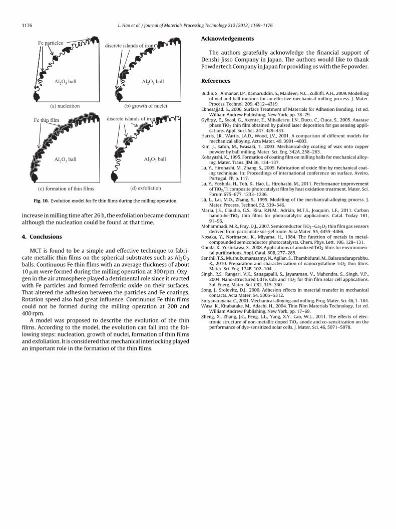
According to the above results and the related analysis, an evo-lution model for Fe thin films during the milling operation wasproposed. It includes the following steps: nucleation, growth ofnuclei, formation of thin films and exfoliation. The schematic dia-gram of the evolution model is given in Fig. 10. Although theevolution of the thin films falls into four different steps, it should
be emphasized that the four steps might take place simultane-ously. Different steps were dominant at different milling time. Forexample, the growth of nuclei can also be found in the region D(Fig. 9(a)) although the nucleation was dominant at that time. With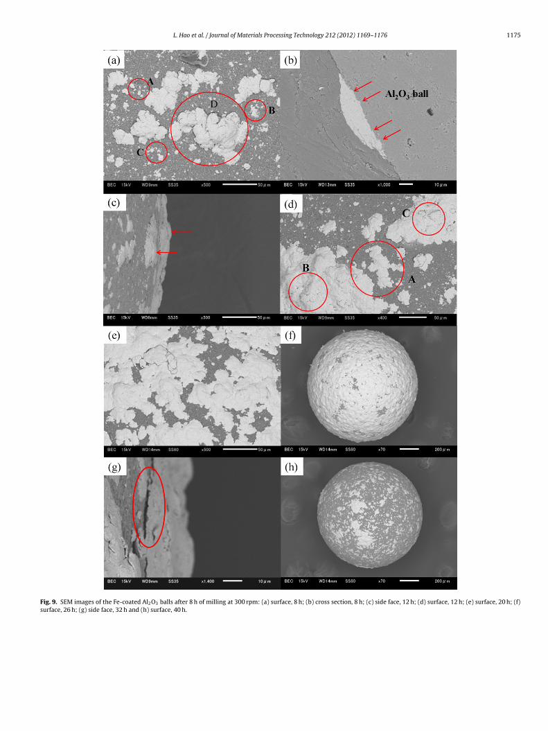
L. Hao et al. / Journal of Materials Processing Technology 212 (2012) 1169–1176 1175
Fig. 9. SEM images of the Fe-coated Al2O3 balls after 8 h of milling at 300 rpm: (a) surface, 8 h; (b) cross section, 8 h; (c) side face, 12 h; (d) surface, 12 h; (e) surface, 20 h; (f)surface, 26 h; (g) side face, 32 h and (h) surface, 40 h.
1176 L. Hao et al. / Journal of Materials Processin
Fe particlesdiscrete islands of iron
(a) nucleation
Al2O3 ball
(b) growth of nuclei
Al2O3 ball
Fe thin film discrete islands of iron
Al2O3 ball Al2O3 ball
ia
4
cb1gwTRc4
filaa
Wasa, K., Kitabatake, M., Adachi, H., 2004. Thin Film Materials Technology, 1st ed.William Andrew Publishing, New York, pp. 17–69.
Zheng, X., Zhang, J.C., Peng, L.L., Yang, X.Y., Cao, W.L., 2011. The effects of elec-tronic structure of non-metallic doped TiO2 anode and co-sensitization on the
(c) formation of thin films (d) exfoliation
Fig. 10. Evolution model for Fe thin films during the milling operation.
ncrease in milling time after 26 h, the exfoliation became dominantlthough the nucleation could be found at that time.
. Conclusions
MCT is found to be a simple and effective technique to fabri-ate metallic thin films on the spherical substrates such as Al2O3alls. Continuous Fe thin films with an average thickness of about0 �m were formed during the milling operation at 300 rpm. Oxy-en in the air atmosphere played a detrimental role since it reactedith Fe particles and formed ferroferric oxide on their surfaces.
hat altered the adhesion between the particles and Fe coatings.otation speed also had great influence. Continuous Fe thin filmsould not be formed during the milling operation at 200 and00 rpm.
A model was proposed to describe the evolution of the thin
lms. According to the model, the evolution can fall into the fol-owing steps: nucleation, growth of nuclei, formation of thin filmsnd exfoliation. It is considered that mechanical interlocking playedn important role in the formation of the thin films.
g Technology 212 (2012) 1169–1176
Acknowledgements
The authors gratefully acknowledge the financial support ofDenshi-Jisso Company in Japan. The authors would like to thankPowdertech Company in Japan for providing us with the Fe powder.
References
Budin, S., Almanar, I.P., Kamaruddin, S., Maideen, N.C., Zulkifli, A.H., 2009. Modellingof vial and ball motions for an effective mechanical milling process. J. Mater.Process. Technol. 209, 4312–4319.
Ebnesajjad, S., 2006. Surface Treatment of Materials for Adhesion Bonding, 1st ed.William Andrew Publishing, New York, pp. 78–79.
György, E., Socol, G., Axente, E., Mihailescu, I.N., Ducu, C., Ciuca, S., 2005. Anatasephase TiO2 thin film obtained by pulsed laser deposition for gas sensing appli-cations. Appl. Surf. Sci. 247, 429–433.
Harris, J.R., Wattis, J.A.D., Wood, J.V., 2001. A comparison of different models formechanical alloying. Acta Mater. 49, 3991–4003.
Kim, J., Satoh, M., Iwasaki, T., 2003. Mechanical-dry coating of wax onto copperpowder by ball milling. Mater. Sci. Eng. 342A, 258–263.
Kobayashi, K., 1995. Formation of coating film on milling balls for mechanical alloy-ing. Mater. Trans. JIM 36, 134–137.
Lu, Y., Hirohashi, M., Zhang, S., 2005. Fabrication of oxide film by mechanical coat-ing technique. In: Proceedings of international conference on surface, Aveiro,Portugal, FP, p. 117.
Lu, Y., Yoshida, H., Toh, K., Hao, L., Hirohashi, M., 2011. Performance improvementof TiO2/Ti composite photocatalyst film by heat oxidation treatment. Mater. Sci.Forum 675–677, 1233–1236.
Lü, L., Lai, M.O., Zhang, S., 1995. Modeling of the mechanical-alloying process. J.Mater. Process. Technol. 52, 539–546.
Maria, J.S., Cláudia, G.S., Rita, R.N.M., Adrián, M.T.S., Joaquim, L.F., 2011. Carbonnanotube-TiO2 thin films for photocatalytic applications. Catal. Today 161,91–96.
Mohammadi, M.R., Fray, D.J., 2007. Semiconductor TiO2–Ga2O3 thin film gas sensorsderived from particulate sol–gel route. Acta Mater. 55, 4455–4466.
Nosaka, Y., Norimatsu, K., Miyama, H., 1984. The function of metals in metal-compounded semiconductor photocatalysts. Chem. Phys. Lett. 106, 128–131.
Onoda, K., Yoshikawa, S., 2008. Applications of anodized TiO2 films for environmen-tal purifications. Appl. Catal. 80B, 277–285.
Senthil, T.S., Muthukumarasamy, N., Agilan, S., Thambidurai, M., Balasundaraprabhu,R., 2010. Preparation and characterization of nanocrystalline TiO2 thin films.Mater. Sci. Eng. 174B, 102–104.
Singh, R.S., Rangari, V.K., Sanagapalli, S., Jayaraman, V., Mahendra, S., Singh, V.P.,2004. Nano-structured CdTe, CdS and TiO2 for thin film solar cell applications.Sol. Energ. Mater. Sol. C82, 315–330.
Song, J., Srolovitz, D.J., 2006. Adhesion effects in material transfer in mechanicalcontacts. Acta Mater. 54, 5305–5312.
Suryanarayana, C., 2001. Mechanical alloying and milling. Prog. Mater. Sci. 46, 1–184.
performance of dye-sensitized solar cells. J. Mater. Sci. 46, 5071–5078.