Embed Size (px)
Citation preview

Kofar-bai D.G., et al. / International Energy Journal 17 (2018) 257 – 270
www.rericjournal.ait.ac.th
257
Abstract – In the present study, numerical simulation of wet compression in a transonic single stage compressor (NASA stage 35) was performed. Thermodynamic processes, heat and mass transfer that greatly influenced the water droplets in the wet compression of the gas turbine compressor were also studied. The results show that, injecting substantial amount of water droplets at the compressor inlet, fully evaporated inside the rotating blade rows, raises the amount of mass flow rates and lower the compression work which greatly influence the compressor performance and maximize its efficiency. Evaporation of water droplets decreases the temperature in front of the rotor blade position, which boosts the moisture content in the air and the formation of vapor. Combination of these factors changes the thermodynamics properties of the fluids, thus, accelerates the convective heat and mass transfer of the mixture. The convective heat between water droplets and compressed air is the primary factor for cooling in the compressor channel and helps to overcome the flow loss caused by water injection and improve the performance and efficiency of the compressor. The overall efficiency of the wet compression process growths to an average of 84%, roughly, 2 percent above the dry and experimental values of 82%. Keywords – evaporation, heat and mass transfer, single stage compressor, water droplets, wet compression.
11. INTRODUCTION
Increase in the compressor inlet temperature, has significant negative effects on the air density which leads to low mass flow rate through the gas turbine and decreases the cycle output, assuming that the cycle pressure ratio, shaft mechanical efficiency, combustion chamber, inlet temperature and isentropic efficiencies of both turbine and compressor remain unchanged. Inlet air cooling is widely used to increase the output of gas turbines during summer months, when the demand for electricity is usually the greatest, however, jet engine thrust also affected with rising temperatures too, making the takeoff roll distance significantly longer.
Gas turbine is indisputably one of the most recent developments of the 20th century and are extensively used for electricity generation. One of the resolutions to boost power output is by using inlet cooling, which means, the schemes in which water or steam is injected to enhance power output [1]. Harsh environmental factor rendered low turbine efficiency, raising the ambient temperature by 1ºC decreases the power output by 0.54 to 0.90% [2]. Among the various systems of inlet cooling, evaporative cooling illustrates that turbine output and heat rate are enhanced as compressor inlet temperature drops [3]. Wet compression techniques is frequently used to expand power output during a hot day, power generation companies around the globe have an estimate of over 1000 gas turbines with such equipment mounted [4]. Water injection is not only a method to upgrade thermodynamics performances, but *College of Power and Energy, Harbin Engineering University, 150001, Harbin China. #Department of Mechanical Engineering, Hassan Usman Katsina Polytechnic, P.O. Box 2052 Katsina state, 820001 Nigeria. 1Corresponding author; Tel: + 86-15636141550 or +234-8181202560 E-mail: [email protected]
rather a means to stabilize the compression system when it approaches stall. The compressor of operational turbine absorbs according to rule roughly half to two-third of useful turbine expansion work [5], [6]. Wet compression mechanism is far beyond to increase and improve performance of the compressor, rather, a means to lower the flow loss, expand the compressor flow capacity and termination of separation [7], [8]. Computer simulation was used to provide the spray model of droplets injected straight into the engine bell mouth and its influence on cooling, and changes in the air density [9].
A comprehensive work to assess inter-stage compressor performance subjected to wet compression using the stage-stacking method was undertaken [10, 11]. Evaporation of an axial compressor with heat transfer model has been predicted, impact of droplets sizes has not been left untouched [12]. Trajectories of water particles in a multi-stage axial compressor has been studied, the outcome predict that droplet flow pattern and residence time depends on the primary settings of the discrete phase [13]. On the investigation of fogging and its effects using in house built model, it reiterate that, the effectual way to increase the benefits of wet compression is to reduce the droplet diameter, thus increases droplet evaporative rate [14]. An evaluation of droplet particles in to wind tunnel of compressor shows reduction in the speed of air due to effect of droplet on high momentum of the airflow [15]. To further understand the effects of inlet cooling, an investigation was carried out on the existing gas turbine in Nigeria, the results show net output power increases around 5-10% and the thermal efficiency growths nearly 2-5% [16]. Comprehensive turbulence modelling of internal combustion engine using re-normalization group (RNG) model, it established forecast on combustion parameters, particularly, soot emissions, and are significantly influenced by the treatment of flow
The Influence of Water Droplets on the Heat and Mass Transfer of the Wet Compression of Single Stage
Compressor
Dayyabu Gambo Kofar-bai*, #, 1 Qun Zheng*, Hai Zhang*, and Adil Malik*
www.rericjournal.ait.ac.th
Kofar-bai D.G., et al. / International Energy Journal 18 (2018) 257 – 270
www.rericjournal.ait.ac.th
258
compressibility in the turbulence model [17]. A collection of slides comprising, gas turbine systems, gas engine systems, high hydrogen project, rig instrumentation, pressure transducers and K-type thermocouples were analyzed for the combined cycle [18]. Characteristic influence of wet compression on a 12 stage compressor with broad geometry has been studied [19]. A computational code to analyze the evaporation influence of inter stage injection of water on the compressor of gas turbine has been evaluated [20]. Induced Rayleigh's damping and gyroscopic impact on cracked rotor and shaft at various frequency were examined and presented [21]. The tip leakage vortex in the blade passage becomes closer to the blade suction surface, prompted greater size of heat transfer coefficient [22]. Injection of alcohols in open-cycle gas turbines during the compression process is considered for intercooling, cases of useful pressure and temperature variation are accounted [23]. Evaluation and measure of the appropriate parameters that describe the engine modes during changes of the exhaust nozzle diameter were studied for turbo jet engines [24]. Nine methods of experimental identifications were compared using measured data from small turbojet engine to create experimental models through programming on Matlab/simulink [25]. Investigation the adaption of different performance maps of centrifugal compressors driven by dual-shaft gas turbines during operation was carried out [26]. Economic analysis of heavy duty industrial gas turbine plant has been investigated using a specified model [27]. In axial flow analysis on industrial gas turbine, imprecise axial gap and tip clearance are two major sources of inefficiency [28].
1.1. Statement of the Problem
From the afore-mentioned contributions of different research groups and different institutional thought, wet compression techniques are indeed necessary tool needed to maintain and boost the power and efficiency and to safe guard the life of the turbine blades. However, there is limited literature that categorically explain the behavior of the influence of water droplets on the heat and mass transfer of the wet compression techniques, what happened from the suction side of the compressor down to its outlet or the domain of the turbine outlet, how does amount of water droplets affects the processes and the influence of water injection rate, these are among the problems that necessitate the present research. A single stage compressor stage 35 was chosen to analyze the influence of heat and mass transfer on the compression of gas turbine and to evaluate the thermodynamic properties using Ansys CFX version 14.5, the performance results are to be compare with dry compressions results as per reference [30]. Water droplets nozzles are positioned between the compressor entrance and rotor blades, the nozzles inject the water droplets at different flowrate in microns and spray volume in percentages of the air mass flow rate.
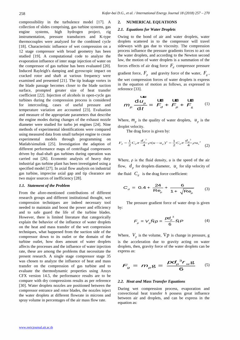
2. NUMERICAL EQUATIONS
2.1. Equations for Water Droplets
Owing to the bond of air and water droplets, water droplets scattered in to the compressor will travel sideways with gas due to viscosity. The compression process influence the pressure gradients forces to act on the water droplets, and according to the Newton second law, the motion of water droplets is a summation of the forces effects of air drag force dF compressor pressure
gradient force, pF and gravity force of the water, gF , the wet compression forces of water droplets is express in the equation of motion as follows, as expressed in reference [33].
g
dd
pp d p
um = F + F + F
t
uuruur uur uur
(1)
Where, pm is the quality of water droplets, pu is the droplet velocity. The drag force is given by:
2 22 21 1( )
2 4 2 4p p
d d p d s
d dF C u u C uπ ρ π ρ= − =
(2)
Where, ρ is the fluid density, u is the speed of the air flow, pd for droplets diameter, su for slip velocity of
the fluid dC is the drag force coefficient:
24 60.4Re 1 Re
dp p
C = + ++
(3)
The pressure gradient force of water drop is given by:
3
6p
p p
dF V p P
p= Ñ = Ñ (4)
Where, pV is the volume, p∇ is change in pressure, g is the acceleration due to gravity acting on water droplets, then, gravity force of the water droplets can be express as:
gg
3
6p w
g p
dF m
p r= = (5)
2.2. Heat and Mass Transfer Equations
During wet compression process, evaporation and convectional heat transfer h possess great influence between air and droplets, and can be express in the equation as:

Kofar-bai D.G., et al. / International Energy Journal 17 (2018) 257 – 270
www.rericjournal.ait.ac.th
259
p pp w p p
T mm C h d T T
t t2
d d= π ( - )+ γ
d d (6)
Where wC is the specific heat of the liquid and γ is the latent heat transfer coefficient of the surface of water droplets and the surface of the air stream. The value of h is obtained from Nusselt number equation.
λ1/ 3 1/ 2Nu 2 0.6Pr Rep
p
hd= = + (7)
Where λ is thermal conductivity, is the Prandtl number. The evaporation of water droplets in the air stream
is related to the temperature, when the temperature of the water droplet is higher than the boiling point, then the evaporation rate is decided by the forced convective heat transfer given in the equation as:
d Nu( )d
p p pm d T T
t
πγ
-= -
l (8)
And when the temperature of the water droplet is lower than the boiling point, the evaporation rate is determined by the following formula:
v sp v v
g
πd 1
Sh log( )d 1
pm M nd D
t M nr
-=
- (9)
Here, vρ and vD are water vapor density and
diffusion coefficient, vM stand for the molar mass of
water vapor, where sn and gn is the mole fraction of water vapor in the vicinity of the water droplet surface and the flow of water respectively. sh is Sherwood number and express as:
1/ 2 1/ 3Sh 2 0.6Re Scm pp
c
k d
D= = + (10)
Where mk is the mass transfer coefficient, cS is the Schmidt number.
In the process of wet compression, the evaporation of water droplets will not only affect the temperature of the air flow in the compressor, but also, affect the composition of the gas flow, which greatly have influence on the properties of the gas. During wet compression process, the pressure of the water vapor is generally lower in an overheated state, because of that, water vapor can be regarded as an ideal gas, wet air as an ideal gas mixture. To calculate wet air moisture content:
0.622 0.622v v
a g v
P Pd
P P P= =
- (11)
Where, vp is the water vapor pressure; ap is the dry
air pressure, and gp is the total pressure of the wet air. According to the properties of the ideal gas mixture, to obtain wet air gas constant and specific heat capacity at constant pressure, the below equations applied:
ga gv ga gvR R R R1 1 1g
d dR
d d d
+= + =
+ + + (12)
1 1 1pa pv pa pv
p
C dC C dCC
d d d
+= + =
+ + +
(13)
Where, gR , gaR , gvR stands for the wet air, dry air
and water gas constant respectively, pC , paC , pvC are specific heat of wet air, dry air and water vapor constant respectively. The definition of wet compression efficiency is given by:
i
w
WW
h = (14)
Where, iW is the ideal wet compression work and wW is the actual wet compression.
(W ) / (1 )i a vW dW d= + + (15)
1 1
1 11 1
W(1 )
a v
a a
k kk k
pa pv
i
C T dC T
d
φ φ− − − + −
=+
(16)
/w averageW M mw= (17)
Where, paC and pvC is the specific heat at constant
pressure of dry air and water vapor respectively, 1T is the total temperature for the inlet airflow, ϕ is the total pressure ratio, d is the diameter content, aK and vK is thermal insulation index for dry air and water vapor, ω is the angular velocity, M is the axial torque for compressor rotor, averagem is the mean flow rate of inlet and outlet compressor. Therefore, wet compression efficiency can be expressed as:
1 1
1 11 1
(1 ) M/ m
a v
a a
k kk k
pa pv
average
C T dC T
d
φ φη
ω
− − − + −
=+
(18)

Kofar-bai D.G., et al. / International Energy Journal 18 (2018) 257 – 270
www.rericjournal.ait.ac.th
260
3. GEOMETRIC MODEL AND BOUNDARY CONIDTION
Computational fluid dynamic (Ansys CFX Version 14.5) is a strong tool used in studying the operation of axial transonic compressor. NASA compressor Stage 35 was selected for the current research. As an outstanding assessment case, this isolated stage was originally designed and tested at the NASA Lewis Research Center in the late 1970s by Reid and Moore [30], [31]. Its design pressure ratio is 1.82 at a mass flow of 20.19 kg/s, and the design rotating speed is 17,188.7 rpm [33].
The geometric design of model and mesh of NASA stage 35 is presented in Figure 1, the compressor consist of rotor blade number 36 and vane number 46, the computational domain grid morphology of about 688232 elements was activated to discretize the computational domain. H-type grid was implemented for both inlet and outlet blocks while J-type grid was used for the blade passage block with 10 layers O-shape type grid around the blade and the leading edge as shown.
Fig. 1. Geometric structure and computational domain of the compressor.
3.1 Methodology
To study the influence of water droplets on the heat and mass transfer of the wet compression of single stage compressor of industrial gas turbine, the compressor speed is set to 17188.7 r/min, and the air used is dry air. The inlet boundary condition is the total temperature, total pressure; the total temperature is 288.15K, while the total pressure is 101325Pa [31].
The exit boundary condition is average static pressure, set to a value of 147515Pa. Dry compression is set to achieved rated flow of 20.188 kg/s. Blade casing and hub are set for the adiabatically wall slip surface. The spray water droplet temperature is 288.15K, and the axial flow rate is 50m/s. No inlet guide vane used, the tip clearance was 0.2mm while the inlet duct shape is circumferential. An effective choice of turbulence model triggers the verification and certainty of the computational simulation-ɛ turbulence model is used in the current research.
Dry and wet simulations were carried out at different amounts of microns and the results were collated and presented below in pictures and graphically methods.
4. RESULTS AND DISCUSSION
When air is sucked in to the compressor at a very high speed, the heat energy content of the air is converted in to kinetic energy, causing a decrease in the temperature, and when the water droplets nozzles are positioned between the compressor entrance and rotor blades, the nozzles injects the water droplets at different flowrate in microns and spray volume in percentages. Once the injected water droplets enters the rotor at the inlet, evaporation start to occur due to difference in vapor
molar concentration between the bulk and droplet surface, evaporation and continuous flow of air causes the temperature to drops, and the temperature remain at minimum near the rotor until evaporation (water evaporates when the temperature is higher than the saturation temperature) and convention (by the motion of moving fluids) heat transfer begins spontaneously, complete evaporation of the discrete phase occurs in the rotating blade rows, which resulted to a sudden rise in temperature beyond the rotor axial position, and through stator toward the compressor bell mouth.
Figure 2 shows trajectory of temperature, pressure and velocity differences between gas and water droplets. Although the heat transfer might happen between gas and water droplets, the dispersed phase cannot absorb the heat from gas fast enough, thus, the temperature difference is so intense at the point of entry. The temperature difference shown in Figure 2a is small in magnitude after crossing the rotor region, and the value is even negative, which means the temperature of gas is less than that of water droplets. Similarly, wet compression brought about an increase in pressure ratio through drop in fluid difference as shown in Figure 2b and increase in velocity of fluid flow due to convection along the compressor channel. In general, these factors are generally essential for increase in compressor output and efficiency as well.
However, keeping the inlet total temperature at 288.15 K, numerical analysis results show that there is consistency in the uniformity of the temperature decrease near the rotor blade as well as increase of temperature in the discrete phase beyond the stator blade position with variation of nozzle diameter. Keeping the rotor span at 50%, contours of temperature, pressure and velocity of rotor region were analyzed and presented in

Kofar-bai D.G., et al. / International Energy Journal 17 (2018) 257 – 270
www.rericjournal.ait.ac.th
261
Figure 3. There is consistency in the temperature and pressure drop across the regions not far beyond the rotor blades as presented in Figures 3a and 3b, respectively.
Whereas, the velocity of the fluid flow increases in the discrete phase of the rotor region.
2(a) Temperature
2(b) Pressure
2(c) velocity
Fig. 2. Trajectory effect of water droplets on the inlet air along the suction side of the compressor.

Kofar-bai D.G., et al. / International Energy Journal 18 (2018) 257 – 270
www.rericjournal.ait.ac.th
262
3(a) Temperature
3(b) Pressure
3(c) velocity
Fig. 3. Contour effect of water droplets on the Rotor region at 50% span.
Fig. 4. Variation of temperature of gas and water droplets along axial position in compressor.

Kofar-bai D.G., et al. / International Energy Journal 17 (2018) 257 – 270
www.rericjournal.ait.ac.th
263
To compliment the explanations of the effect of water droplets on the temperature of air along the axial compressor passage explained above, a comprehensive graph that show variation of temperature for both dry, wet and water injection droplet compression process along the axial position is presented in Figure 4. From the numerical results, only water droplets of 5 microns or below, gives uniform evaporation, decreases the temperature near the rotor and raises the temperature in the discrete phase of the stator blade, the temperature drops to as low as 267K near the rotor and rises to above 304K beyond the stator blade. However, increase in the injected water droplets amount to 10 microns and 20 microns moves the lower temperature a bit higher and could not attain its maximum value in the discrete phase. With 10 micron the temperature drops coarsely low near the rotor to a value of 280 K and rises to 290 K. Dry air, and wet air attained maximum temperature value of around 330K. Choosing adequately smaller water droplets gives bigger volume and ratio of water droplets area, which have greater effect on flow of heat transfer. Droplets with minimum amount of less than or equal to 5 microns got minimum temperature drop and influence speedy evaporation which enhance the compressor performance. These graphical results agree with literature references [31], [32], where, low injected diameter gives better evaporation, mass flow rate and increases compressor efficiency.
The evaporation of water droplets changes the composition and thermodynamic properties of the air flow, hence, the specific heat at constant volume changes with spray volume. As shown in Figure 5, water droplets at injection rate of 5 micron under different spray volume produce contours of specific heat on the stator blade. As the spray volume increases, the ability of water to absorbs more heat from the air decreases, generates lower evaporative rate of the water droplets, when this phenomenon coupled with conventional heat transfer effect caused by the air in the compressor it generates specific heat, the specific heat generated is inversely proportional to the quantity of water injected and spray volume. Specific heat decreases in unit magnitude from 727.0 J/kg K in Figure 5a, to 720.0 J/kg K in Figure 5b. Decrease in the amount
of specific heat is as a result of the formation of more moisture in the compression (as explained in Figure 9). This signifies that, specific heat of water droplets at constant volume and high spray volume is not so good for the wet compression performances.
Circumferential plots of the contour of entropy at the blade trailing edge during compression process of the compressor is presented in Figure 6 for both dry and wet compression. Entropy is an essential thermodynamic quantity of the system which varies with motion and amounts of water droplets during compression process. Entropy is usually minimum at the inlet and blades trailing edge, and is expected to be high in proportion to the amount of water droplets and heat generation through evaporation. The amount of the entropy increases rapidly along the axial direction towards the trailing edge of the blade due to separations and shockwaves derived high static pressure from droplets of wet compression. Figure 8a shows the amount of entropy is below zero at the inlet for dry compression and then it rises to around 65 J/kgK at the blade trailing edge where as Figure 8b have its corresponding entropies above zero at the inlet and blades trailing edges which equally advances to 130 J/kgK for 5 microns, respectively.
Increase in the initial particle temperature does not influence the rate of evaporation significantly, even though it boosts the vapor pressure at the liquid-vapor interface of the particle. Droplets particles cools down briefly in front of the rotor since the thermal response time is small before the evaporation begins. Categorically, it shows that, water droplets of 5 microns gives better evaporative rate within the shortest distance possible before the rotor blade position and if the water droplet diameter raises to 10 and 20 microns not all the particle could be evaporated before reaching the rotor and stator channels, some amount of the particle would be trapped on the wall and blade surfaces. From Figure 7 the maximum evaporative rate of 5 microns reaches little above 160 g/s, while the minimum on 20 microns spotted at 60 g/s.
Fig. 5. Specific heat of water droplets in the compressor stator blades at different spray volume.

Kofar-bai D.G., et al. / International Energy Journal 18 (2018) 257 – 270
www.rericjournal.ait.ac.th
264
(a) Dry compression
(b) 5 microns compression
Fig. 6. Variation of entropy distribution along the trailing edge of the blade.
Fig. 7. Average evaporation velocity of water droplets in the compressor.
The degree of evaporation of the liquid flow
through the compressor during the wet compression drops with increase in the spray volume. Increase in the spray volume means more liquid water content in the air stream, even though, it might raise the evaporation and temperature of the water droplet. Moreover, due to the evaporation effect, the ratio of the evaporation and spray volume reduces, causing decline in the evaporative rate in the compressor.
The average specific heat of water droplets at constant pressure is plotted against water droplet injection rate at constant spray volume. From the graph in Figure 8, smaller amount of 5 microns gives better average specific heat of 1007.5 J/kg K, while higher amount of 20 microns gives 1005.3 J/kg K, which is relatively closer to the value of 1004.5 J/kg K for average specific heat of dry compression.
Kofar-bai D.G., et al. / International Energy Journal 17 (2018) 257 – 270
www.rericjournal.ait.ac.th
265
Fig. 8. Average specific heat of water droplets at constant pressure.
(a) 5 microns compression
(b) 10 microns compression
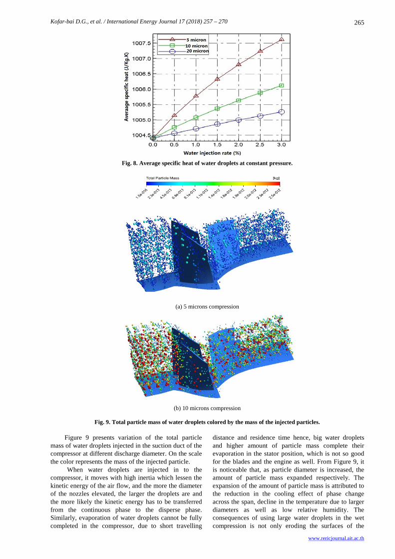
Fig. 9. Total particle mass of water droplets colored by the mass of the injected particles. Figure 9 presents variation of the total particle mass of water droplets injected in the suction duct of the compressor at different discharge diameter. On the scale the color represents the mass of the injected particle.
When water droplets are injected in to the compressor, it moves with high inertia which lessen the kinetic energy of the air flow, and the more the diameter of the nozzles elevated, the larger the droplets are and the more likely the kinetic energy has to be transferred from the continuous phase to the disperse phase. Similarly, evaporation of water droplets cannot be fully completed in the compressor, due to short travelling
distance and residence time hence, big water droplets and higher amount of particle mass complete their evaporation in the stator position, which is not so good for the blades and the engine as well. From Figure 9, it is noticeable that, as particle diameter is increased, the amount of particle mass expanded respectively. The expansion of the amount of particle mass is attributed to the reduction in the cooling effect of phase change across the span, decline in the temperature due to larger diameters as well as low relative humidity. The consequences of using large water droplets in the wet compression is not only eroding the surfaces of the

Kofar-bai D.G., et al. / International Energy Journal 18 (2018) 257 – 270
www.rericjournal.ait.ac.th
266
blades but rather causing a sluggish movement of the particles.
Droplets of less than 5 microns which correspond to particle mass of 1.07e-12 kg could be fully evaporated, transported by convection effects and gives out better compressor efficiency as explained in references [1], [6], [7], while, water droplets of less than
or equal to 10 micron which equally corresponds to 2.0e-12 kg of particle mass is relatively consider in some literatures [12], however, water droplets of total particle mass above 2.0e-12 kg which corresponds to above 10 microns gives out low performance and efficiency of the compressor.
Fig. 10. Variation of moisture content along axial position in compressor.
Fig. 11. Mass flow rate at different heat transfer in the compressor.
Irrespective of the position along axial compressor, injected water droplets produce continuous evaporation and wet air moisture content more specifically, in the stator blade area, where, the slope of the curve elevated. Minimum amount of water droplet with high spray volume of like 5 micron 2% gives better amount of moisture, this is because, smaller water droplets provides adequate evaporation, and when the evaporation area become larger, the heat transfer and the temperature expands higher and higher simultaneously, so, with spray volume is raises further, it equally increases the amount of evaporation of water droplets and it subsequently, drops the temperature, which upshot the moisture content. Consequently, more amount of water droplets in micron means lessen the amount of moisture, low evaporation and minimum efficiency of the compressor. For attaining an adequately good amount of moisture in Figure 10 spray volume should
not exceed 2%, because it also has effect on the specific heat of the droplets.
Mass flow rate of compressor inlet air for different conditions of heat transfers is plotted against water injection rate for both dry condition and water droplets. In Figure 11 during the evaporation process due to either high temperature or low moisture partial pressure, the water droplets are transported away due to convection and diffusions effects. The higher the water injection rate the better the evaporation and convection which subsequently, elevates the mass flow rate to 20.55 kg/s against the dry compression and experimental values of 20.2 kg/s and 20.19 kg/s, respectively. This is because the degree of resistances increases when evaporation and convection effect were taken simultaneously, the water droplets have significantly amount of evaporation which overcome the resistance drag force, so, the average flow rate of evaporation and convection mass flow rate has a

Kofar-bai D.G., et al. / International Energy Journal 17 (2018) 257 – 270
www.rericjournal.ait.ac.th
267
potential that exceeded dry mass flow rate in the compression process. However, consistency evaporation causes a gradual temperature decrease due to weak intensity of water droplets and drag force resistance, and since there is no cooling effect on the evaporation, the drag force resistance increases proportionally with spray volume, hence, the gas mass flow rate tends to be lower. Similarly, in the case of convective heat transfer, the water droplet has associated cooling effect on the airflow, but the degree of cooling is limited, hence, therefore, the mass flow rate still remains lower. Figure 12 highlights the behavior of mass flow rate for the inlet and outlet flow of wet compression. In a
similar trend to Figure 11, mass flow rate relationship with discharge diameter and spray volume is plotted and for various amount of the microns, the mass flowrate at the outlet exceeded that of the inlet irrespective of the water injection rate, because of the evaporation of water droplets in to the air and as usual smaller water droplets gives out good amount of mass flow than dry compression which consequently gives better efficiency. With spray volume of 2% water injection rate for both 5microns and 10 microns gives mass flow rate value relatively above dry compression amount of 20.2 kg/s, with 5 microns at outlet reaching 20.60 kg/s.
Fig. 12. Mass flowrate at inlet and outlet against water injection rate.
Fig. 13. Compressor efficiency with different flowrate for wet and dry compression.
Fig. 14. Compressor efficiency with different mass transfer of wet and dry compression.

Kofar-bai D.G., et al. / International Energy Journal 18 (2018) 257 – 270
www.rericjournal.ait.ac.th
268
Compressor efficiency for different mass flow rate and different heat transfer is presented in Figure 13 and Figure 14 respectively, it can be seen from Figure 13 that, for water droplet with particle size of 5-micron 2.5% injection rate, efficiency reaches to 84.55% against 82.40 % of dry compression, nearly, an increase of 1.65 percent, 2.14 percent and 2.38 percent at injection rate of 1%, 2% and 3%, respectively. Similarly, for 10 microns there is no much significance difference between wet and dry compression efficiencies, 0.25 percent decline is observed at water injection rate of 3%, and for the particle size of 20 microns, 3% spray volume of wet compression efficiency with respect to dry compression reduces by 2.8 percent.
Subsequently, on Figure 14, the heat and mass transfer of water droplets on the compressor performance were highlighted, the droplet evaporation and convection of wet compression effect is very important on the efficiency, furthermore, convection heat transfer and water droplet are the primary factor for compressor cooling, while, water droplet evaporation absorbs heat from the air, reduces the temperature of water at the same time, raises the temperature difference between water and air, promote the water droplets and air convective heat transfer, therefore, evaporation and convective heat transfer in the wet compression of compressor gives out high efficiency against dry compression than evaporation and convection acting alone, with efficiency increment of 2.41 percent at 2.5% water injection rate.
5. CONCLUSIONS
In the present work on the simulation of wet compression to analyze influence of water droplet heat and mass transfer on the wet compression of gas turbine compressor, the behavior of the compressor was analyzed to ascertain the performance effect of heat and mass transfers under various injection diameters, the results of wet compression are compared with experimental work of NASA stage 35 and the results suggest that:
• the gas turbine compressor performance heat rate and compressor performance increases as the diameter of injected water droplets reduces and water temperature elevated;
• Droplet evaporation mostly absorbs water heat while convective heat transfer brings cooling to the compressor, therefore, for effective compressor performance, evaporation and convection heat of water droplets is mutual and consistent processes;
• Some of the benefits of wet compression is not only limited to the water flowrate, but closely extended to the nozzle diameter, sufficiently, smaller amount of water injection squarely improves compressor and engine performance.
• Total particle mass of water droplets increases with increase in the amount of water droplets, which is not so good to the compressor, increasing amount of the particle reduces the evaporation and convective heat transfer of the
compression process, by the action of sluggish movement in front and along the rotor blade position. A precise amount less than 10 micron is substantially needed to avoid the effects and cause no harm to the compression process.
ACKNOWLEDGMENTS
The authors wish to thank the financial support of National Natural Science Foundation of China (Grant No. 51409067) and the support of Aeronautical Science Foundation of China (Grant No. 201410P6003).
NOMENCLATURE
R Mass Fraction
d Mean particle diameter [m]
de Measure of the fineness [m]
mp Mass of water droplet [kg]
up Velocity of water droplet [m/s]
t Time [s] Fp Pressure gradient force of water droplet [N]
Fg Gravity of water droplet [N]
Fd Drag force of water droplet [N]
ρ Density of gas [kg/m3]
u Velocity of gas [kg/m3]
dp Diameter of water droplet [m]
us Slip velocity between gas and water droplet [m/s]
Cd Drag coefficient
Rep Reynolds number of water droplet
μ Viscosity of gas [Pa·s]
Vp Volume of water droplet [m3]
▽P Pressure gradient force [kg/(m2·s2)]
ρw Density of water [kg/m3]
g Gravitational acceleration [m/s2]
Weg Weber number of water droplet for aerodynamic breakup
σp Surface tension coefficient [N/m]
Kbr Breakup frequency [Hz]
Wew Weber number of water droplet for impingement
un Normal velocity of water droplets [m/s]
Aw Factor of wall surface roughness
μw Viscosity of water [Pa·s]
km Mass transfer coefficient [m/s]
Dc Molecular diffusion coefficient [m2/·s]
ρs Density of gas near droplet surface [kg/m3]
ρg Density of ambient gas [kg/m3]

Kofar-bai D.G., et al. / International Energy Journal 17 (2018) 257 – 270
www.rericjournal.ait.ac.th
269
Cw Specific heat of water [J/(kg·K)]
γ Latent heat of evaporation [J/kg]
h Surface coefficient [W/(m2·K)]
Nu Nusselt number
Pr Prandtl number
REFERENCES
[1] Lee S.W., Kim S.U. and Kim K.H., 2012. Aerodynamic performance of winglets covering the tip gap inlet in a turbine cascade. International Journal of Heat and Fluid Flow 34: 36-46.
[2] Chaker M. and C.B. Meher-Homji. 2011. Gas turbine power augmentation: parametric study relating to fog droplet size and its influence on evaporative efficiency. Journal of Engineering for Gas Turbines and Power 133: 092001.
[3] Jonsson M. and J. Yan. 2005. Humidified gas turbines—a review of proposed and implemented cycles. Energy 30: 1013-1078.
[4] Montalvo-Catano G. and W.F. O’Brien. 2011. Performance modeling of a power generation gas turbine with wet compression. In Proceedings of ASME 2011 Turbo Expo: Turbine Technical Conference and Exposition, June 6-10, Vancouver, British Columbia, Canada, pp. 665-674.
[5] Zheng Q., Sun Y., Li S., and Wang Y., 2002. Thermodynamic analyses of wet compression process in the compressor of gas turbine. In Proceedings of ASME Turbo Expo 2002: Power for Land, Sea, and Air, June 3-6, Amsterdam, The Netherlands, pages 487-496, Part A and B.
[6] Li M. and Q. Zheng. 2004. Wet compression system stability analysis: Part II—simulations and bifurcation analysis. In Proceedings of ASME Turbo Expo 2004: Power for Land, Sea, and Air, June 14-17, Vienna, Austria, pp. 713-721.
[7] Sun L., Zheng Q., Li Y., and Bhargava R., 2011. Understanding effects of wet compression on separated flow behavior in an axial compressor stage using CFD analysis. Journal of Turbomachinery 133: 031026.
[8] Sun L., Zheng Q., Li Y., Luo M., and Bhargava R.K., 2013. Numerical simulation of a complete gas turbine engine with wet compression. Journal of Engineering for Gas Turbines and Power 135: 012002.
[9] Sexton M.R., Urbach H.B., and Knauss D.T., 1998. Evaporative compressor cooling for NOx suppression and enhanced engine performance for naval gas turbine propulsion plants. In Proceedings of ASME 1998 International Gas Turbine and Aeroengine Congress and Exhibition, June 2-5, Stockholm, Sweden.
[10] Wang T. and J.R. Khan. 2008. Overspray and interstage fog cooling in compressor using stage-stacking scheme: Part 1—development of theory and algorithm. In Proceedings ASME Turbo Expo
2008: Power for Land, Sea, and Air, June 9-13, University of New Orleans, USA, pp. 99-109.
[11] Wang T. and J.R. Khan. 2008. Overspray and interstage fog cooling in compressor using stage-stacking scheme: Part 2—case study. In Proceedings of ASME Turbo Expo 2008: Power for Land, Sea, and Air, June 9-13, University of New Orleans, USA, pp. 111-121.
[12] Matz C., Cataldi G., Kappis W., Mundinger G., Bischoff S., Helland E., and Ripken M., 2010. Prediction of evaporative effects within the blading of an industrial axial compressor. Journal of Turbomachinery 132: 041013.
[13] Mustafa Z., Pilidis P., Teixeira J.A.A., and Ahmad K.A., 2006. CFD aerodynamic investigation of air-water trajectories on rotor-stator blade of an axial compressor for online washing. In Proceedings of ASME Turbo Expo 2006: Power for Land, Sea, and Air, May 8-11, Barcelona, Spain, pp. 1385-1394.
[14] Hartel C. and P. Pfeiffer. 2003. Model analysis of high-fogging effects on the work of compression. In Proceedings of ASME Turbo Expo 2003, International Joint Power Generation Conference, June 16-19, Atlanta, Georgia, USA, pp. 689-698.
[15] Ulrichs E. and F. Joos, 2006. Experimental investigations of the influence of water droplets in compressor cascades. In Proceedings of ASME Turbo Expo 2006: Power for Land, Sea, and Air, May 8-11, Barcelona, Spain, pp. 221-230.
[16] Oyedepo S.O. and O. Kilanko. 2014. Thermodynamic analysis of a gas turbine power plant modelled with an evaporative cooler. International Journal of Thermodynamics 17(1): 14-20.
[17] Han Z. and R.D. Reitz. 1995. Turbulence modeling of internal combustion engines using RNG κ-ε models. Combustion Science and Technology 106: 267-295.
[18] Christodoulou M., Moodie K., Rattigan W., and Ewan B., 2016. Safe operation of combined cycle gas turbine and gas engine systems using hydrogen rich fuels. In Proceedings of EVI-GTI and PIWG Joint Conference on Gas Turbine Instrumentation, September 27-19, Berlin, Germany, pp. 1-36.
[19] White A. and A. Meacock. 2003. An evaluation of the effects of water injection on compressor performance. In Proceedings of ASME Turbo Expo 2003 International Joint Power Generation Conference, June 16-19, Atlanta, Georgia, USA, pp. 181-189.
[20] Bagnoli M., Bianchi M., Melino F., Peretto A., Spina P., Ingistov S., Bhargava R.K., 2008. Application of a computational code to simulate interstage injection effects on GE Frame 7EA Gas Turbine. Journal of Engineering for Gas Turbines and Power 130: 012001.
[21] Kulesza Z. and J.T. Sawicki. 2017. Parametrically induced damping in a cracked rotor. Journal of Engineering for Gas Turbines and Power 139: 012505, 2017.

Kofar-bai D.G., et al. / International Energy Journal 18 (2018) 257 – 270
www.rericjournal.ait.ac.th
270
[22] Zhong F., Zhou C., Ma H., and Zhang Q., 2017. Heat transfer of winglet tips in a transonic turbine cascade. Journal of Engineering for Gas Turbines and Power 139: 012605.
[23] Bisio G. and F. Devia. 1997. Interstage cooling in compressors for gas turbines. In Proceedings of the 32nd Intersociety Energy Conversion Engineering Conference - IECEC-97, July 27 – August 1, Honolulu, USA, pp. 1592-1599.
[24] Komjáty M., Főző L., and Andoga R., 2015. Experimental identification of a small turbojet engine with variable exhaust nozzle. In Proceedings of IEEE 16th International Symposium on Computational Intelligence and Informatics (CINTI), November 19-21, Budapest, Hungary, pp. 65-69.
[25] Nyulászi L., Andoga R., Butka P., and Gašpar V., 2016. Comparison of experimental identification methods using measured data from a turbojet engine. In Proceedings of IEEE 14th International Symposium on Applied Machine Intelligence and Informatics (SAMI), January 21-23, Herlany, Slovakia, pp. 23-27.
[26] Cortinovis A., Zovadelli M., Mercangoz M., Pareschi D., De Marco A. and Bittanti S., 2014. Online adaptation of performance maps for centrifugal gas compressors. In Proceedings of IEEE European Control Conference (ECC), June 24-27, Strasbourg, France, pp. 1036-1041.
[27] Liang X., Xue Y., and Li Z., 2011. Techno-economic analysis of applying China's R0110 gas turbine in IGCC plants. In Proceedings of IEEE International Conference on Materials for
Renewable Energy & Environment (ICMREE), May 201-22, Shanghai, China, pp. 1674-1677.
[28] Elwan W.M., Shaalan M.R., Nassief M.M., and Gobran M.H., 2016. Computed effect of varying tip clearance and axial gap on gas turbine stage performance part (I): (steady flow). The Egyptian International Journal of Engineering Sciences and Technology. 20: 68-74.
[29] Nikolaidis T., 2008. Water ingestion effects on gas turbine engine performance. Cranfield University, Bedfordshire, England, pp. 18-19.
[30] Reid L. and R.D. Moore. 1978. Design and overall performance of four highly loaded, high speed inlet stages for an advanced high-pressure-ratio core compressor. National Aeronautics and Space Administration (NASA), Cleveland, Ohio, USA.
[31] Moore R.D. and L. Reid. 1982. Performance of single-stage axial-flow transonic compressor with rotor and stator aspect ratios of 1.63 and 1.78, respectively, and with design pressure ratio of 1.82. National Aeronautics and Space Administration (NASA), Cleveland, Ohio, USA.
[32] Bhargava R. and C. Meher-Homji. 2002. Parametric analysis of existing gas turbines with inlet evaporative and overspray fogging. In Proceedings of ASME Turbo Expo 2002: Power for Land, Sea, and Air, June 3-6, Amsterdam, The Netherlands, pp. 387-401.
[33] Dayyabu G.K.B., Zhang H., Zheng Q. and Ahmad S., 2017. Flow assessment on the effects of water droplets on rotor region of wet compression. Defect and Diffusion Forum 374: 131-147.