Embed Size (px)
Citation preview
1
ME456: Mechatronics Systems Design
Robotics with The BOEbot v 2.2Chapter 7:
Navigating with Infrared Headlights
Prof. Clark J. RadcliffeMechanical Engineering
Michigan State University
http://www.egr.msu.edu/classes/me456/radcliff
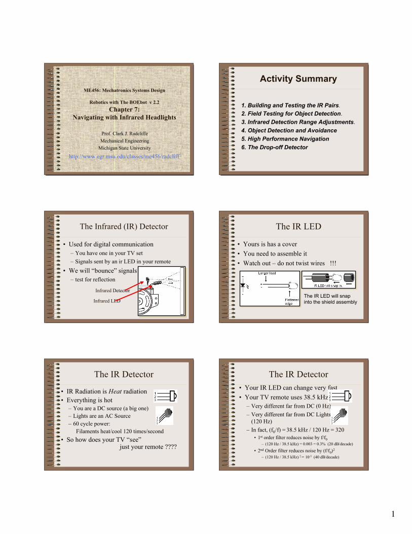
Activity Summary
1. Building and Testing the IR Pairs.2. Field Testing for Object Detection.3. Infrared Detection Range Adjustments.4. Object Detection and Avoidance5. High Performance Navigation6. The Drop-off Detector
The Infrared (IR) Detector
• Used for digital communication– You have one in your TV set– Signals sent by an ir LED in your remote
• We will “bounce” signals– test for reflection
Infrared LED
Infrared Detector
The IR LED
• Yours is has a cover• You need to assemble it• Watch out – do not twist wires !!!
The IR LED will snapinto the shield assembly
The IR Detector
• IR Radiation is Heat radiation• Everything is hot
– You are a DC source (a big one)– Lights are an AC Source– 60 cycle power:
Filaments heat/cool 120 times/second• So how does your TV “see”
just your remote ????
The IR Detector• Your IR LED can change very fast• Your TV remote uses 38.5 kHz
– Very different far from DC (0 Hz)– Very different far from DC Lights
(120 Hz)– In fact, (f0/f) = 38.5 kHz / 120 Hz = 320
• 1st order filter reduces noise by f/f0– (120 Hz / 38.5 kHz) = 0.003 = 0.3% (20 dB/decade)
• 2nd Order filter reduces noise by (f/f0)2
– (120 Hz / 38.5 kHz) 2 = 10-5 (40 dB/decade)

2
BoE Connections
It’s crowded…Be neat and use shorter wires!!!
BoE Connections
• I changed connections to prevent shortsXP2
XP7 These changes
prevent crossedwires
XP1
The FREQOUT Trick
• FREQOUT Pin, Duration, Freq1– Designed to produce audio tones– “Aliasing” produces a 2nd “harmonic” tone
centered about 32678 Hz
“Harmonic” is low for high input frequencies:harmonic frequency = 65536 – Freq1, Freq1 ≥ 32678
“Harmonic “is high for low input frequencies:harmonic frequency = 65536 – Freq1, Freq1 ≤ 32678
Testing Your Detector
• Use Code in text BUT change pins• Avoid Shorts – No Crossed Resistors'Symbol DefinitionSpeaker PIN 4 'Piezospeaker pin (Output)LeftDetector PIN 9 'Left IR Detector Pin (input)LeftirLED PIN 8 'Left IR LED drive (output)LeftLED PIN 7 'Left Indicator LED (output)LeftServo PIN 13RightDetector PIN 0 'Right IR Detector Pin (input)RightirLED PIN 1 'Right IR LED drive (output)RightLED PIN 2 'Right Indicator LED (output)RightServo PIN 12
Orient your LEDs and Detectors
• Point them out to Left and Right
Left
Center
Right
Easy to Change Symbols
Pins defined by symbolsallow you to use symbols in your code directly
' Robotics with the Boe-Bot - TestIrPair.bs2' Test IR object detection circuits
' {$STAMP BS2}
' {$PBASIC 2.5}
'Symbols
LeftDetector PIN 9 'Left IR Detector Pin (input)LeftirLED PIN 8 'Left IR LED drive (output)
LeftLED PIN 7 'Left Indicator LED (output)
RightDetector PIN 0 'Right IR Detector Pin (input)RightirLED PIN 1 'Right IR LED drive (output)
RightLED PIN 2 'Right Indicator LED (output

3
The TestIrPair Program'VariablesirLeftSense VAR BitirRightSense VAR Bit
'Declarations INPUT LeftDetector OUTPUT LeftirLED OUTPUT LeftLED INPUT RightDetector OUTPUT RightirLED OUTPUT RightLED
The Main Program Loop
DO FREQOUT LeftirLED, 1, 38500 irLeftSense = LeftDetector FREQOUT RightirLED, 1, 38500 irRightSense = RightDetector
DEBUG HOME, "irLeftSense = ", BIN1 irLeftSense LeftLED=~irLeftSense DEBUG CR, "irRightSense = ", BIN1 irRightSense RightLED=~irRightSense
PAUSE 100LOOP