Embed Size (px)
Citation preview
THE INTEGRATION OF WATER LOOP HEAT PUMPAND BUILDING STRUCTURAL THERMAL STORAGE SYSTEMS
Thomas J. Marseille and J. Steven SchliesingPacific Northwest Laboratory
Commercial buildings often have extensive periods where one space needs coolingand another heating.. Even more common is the need for heating during one part ofthe day and cooling during another in the same spaces" If a building's heating andcooling system could be integrated with the building's structural mass such that themass can be used to collect, store, and deliver energy, significant energy might besaved.
Computer models were developed to simulate this interaction for an existing officebuilding in Seattle, Washington that has a decentralized water-source heat pumpsystem.. Metered data available for the building was used to calibrate a "base" buildingmodel (te.., nonintegrated) prior to simulation of the integrated system.
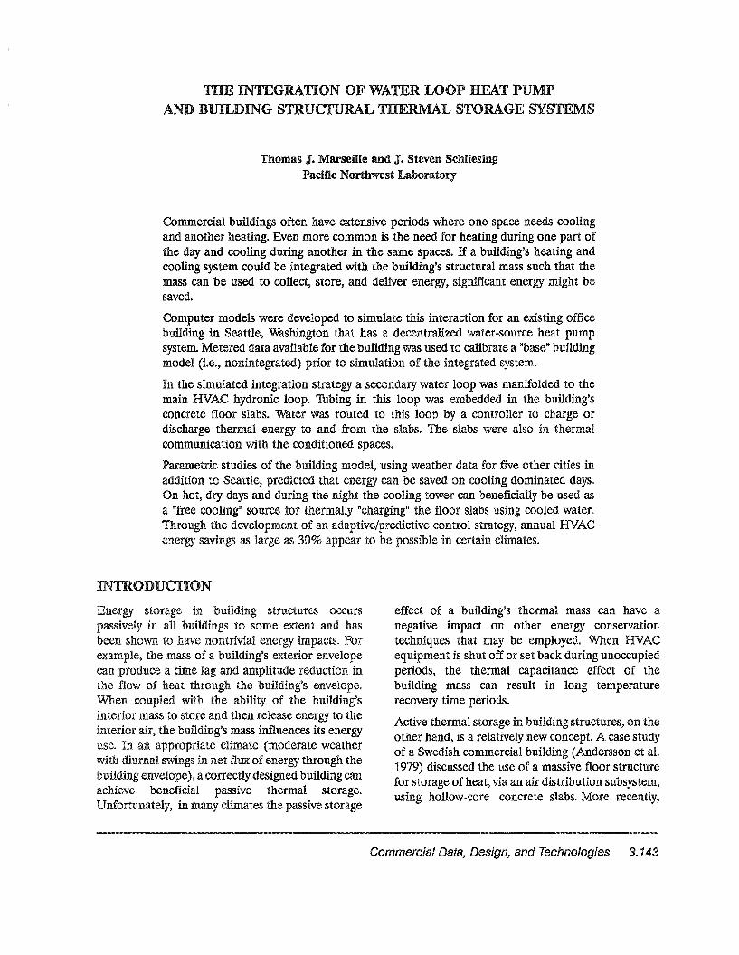
In the simulated integration strategy a secondary water loop was manifolded to themain HVAC hydronic loop.. Thbing in this loop was embedded in the building'sconcrete floor slabs.. Water was routed to this loop by a controller to charge ordischarge thermal energy to and from the slabs.. The slabs were also in thermalcommunication with the conditioned spaces..
Parametric studies of the building model, using weather data for five other cities inaddition to Seattle, predicted that energy can be saved on cooling dominated days.On hot, dry days and during the night the cooling tower can beneficially be used asa "free cooling" source for thermally "charging" the floor slabs using cooled water..Through the development of an adaptive/predictive control strategy, annual HVACenergy savings as large as 30% appear to be possible in certain climates"
INTRODUCTION
storage in structures occursna5;slv'elv in all buildings to some extent and hasbeen shown to have nontrivial Forexample, the mass of a building's exterior envelopecan produce a time and amplitude reduction inthe flow of heat through the building's envelope..When coupled with the of the building'sinterior mass to store and then release energy to theinterior the building's mass influences its energyuse.. In an appropriate climate (moderate weatherwith diurnal swings in net flux ofenergy through theOUl101IU! envelope), a correctly designed building canachieve beneficial passive thermal storage..
Jnf()rtl11n2ltelv,. in many climates the passive storage
effect of a building's thermal mass can have anegative impact on other energy conservationtechniques that may be employedfO When HVACequipment is shut off or set back during unoccupiedperiods, the thermal capacitance effect of thebuilding mass can result in long temperaturerecovery time periods..
Active thermal storage in building structures, on theother hand, is a relatively new concept A case studyof a Swedish commercial building (Andersson et at1979) discussed the use of a massive floor structurefor storage of heat, via an air distribution subsystem,using hollow-core concrete slabs.. More recently,
Commercial Data, Design, and Technologies 3.. 143
research has also looked at "precoolingtt buildingsat night and on weekends with supply air to reducedaytime cooling loads (Ruud et at 1990); (Braun1990)$ However, using a water distribution subsystem to charge and discharge the energy stored inthe structure appears to have the potential forbetter control in most applications, because waterhas a higher heat capacitance than air and thusallows a more thorough and rapid purging of storedheat In addition, the practical considerationsassociated with using the floor slab as the storagemedium in this manner-...te.., material compati~
bilities, component connections, and configurationof the piping in the water loop--have already beenaddressed in past research, as embedding waterpipes within concrete is a proven concept,
APP OACH
The interactions of a water loop heat pump systemintegrated via a water distribution subsystem to thebuilding structural mass were studied, and the effecton whole-building energy performance analyzed~
This integration strategy is referred to as theHU]lQUU! Structural Thermal Storage (BSTS)
arseille et at 1989)~
A model was first to simulatean existing base building located in Seattle,wa:snl]n2t'OD.$ Metered data available for the buildingwere used to calibrate the model to ensure thatthe analysis would information closelyrelated to the of a real ThebU1.1<11IU! model with the BSTS system added to it(see Figure 1) was then simulated and the resultscompared to the results of the base case building~
Simulations were also rformed, for both the baseOUlletlIU! model and the model with the
weather data for five otherlocations in the United Statess In the following"'~""'li..Il.V.ll.jiJJI'b the simulation base building
BSTS energy usageand BSTS optimization
considerations are discussed~
e Thansient System Simulation (lRNSYS).... -J"o..... - ........... was selected as the analysis tool for this
3.. 144 Marseille and Schliesing
study because it can perform a dynamic whole...building system analysis.. A building load model isavailable in TRNSYS that uses temperature levelcontrol, a dynamic modeling approach, as opposedto energy rate control used in programs such asDOE...2.. In temperature level control, roomconditions are determined by not only the ambientconditions, but also by heating and coolingequipment inputs~ The interactive feedback of thebuilding subsystems on building load is thuscaptured.. Because the objective of this project wasto study the dynamic interaction of the buildingsubsystems, the temperature level control modelingapproach was required41 Also, because TRNSYS wasdesigned with a modular structure, it can be readilymodified and new building subsystem componentmodels incorporated (Solar Energy Laboratory
3)..
Five new component models not inclu.ded in thestandard TRNSYS library were developed specifically for this study: a cooling tower, heat pump,water boiler, water loop thermostat (used to controlcooling tower and boiler operations), and the floorslab used. :in the BSTS system.. The boiler andthermostat are extended versions of existing
NSYS modules.. e heat pump model wasent:1reJ[v new and used a simple extension of anempirical fit to the manufacturer's rating data todetermine exit air and water conditions and powerconsumption.. The cooling tower model wasdeveloped to compute exit water temperatures byusing a approach developed by Whillier(1976)0 Because no data on the actual tower in theOU1IUIIUI was the fill characteristic "factorof meritft used in the model is a value cited astypical Whiltier, based on available data forseveral commercial towerSe
A numerical slab heat transfer model was developedto simulate the building floor slabs and the integrated water piping system within. the slabs$ Themodel solves the two-dimensional unsteady conduction equation in a cartesian coordinate space byapproximating the temperature field using a centraldifferencing scheme.. These formulas are applied inthe model at each node in a user-specified grid thatincludes portions of the slab, the pipe wall, and thewater..
tEXPANSION TANt<
BOILER
COOLER BYPASS
PRIMARYLOOP TEMPSENSOR
1~ lnt~~r!rtltet1 BSTSand Heat Subsystems
The the direction of thewater flow is not modeled in the numerical solutionoJ..u..,a.iVGMlJ.~ an iterative is used to determinean (average of slab inlet andoutlet of the water~ Because theembedded are laid in multipleDaI~all~el circuits at high flow rates, assuming the
to be all at this temperature is reasonable..the of the piping system
meant only the smallest common element (half ofthe pipe and its associated slab) needed to beanalyzed in the numerical model.
At each call during a simulation time step, the slabmodel uses as its inputs the outputs from otherTRNSYS subsystem components, including slabsurface temperatures (i.e.., top and bottom) and inletwater flow rate and bulk temperature" The amount
Commercial Data, Design, and Technologies 3.. 145
of heat transferred from the fluid to the slab andthat transferred. from the slab surfaces is calculated..These then constitute the outputs from the slabcomponent modet
BASE BUILDING MODEL
The base building model is based on an existing sixstory office building in Seattle that was monitoredby Seattle City Light (SCL) between 1983 and 1985(Cleary and Crimmin 1986). It is typically occupied50 hours a week, 8 a.m. to 6 p"m., Monday throughFriday; the average occupancy level is 400 people.The structure was constructed in 1976 on a concreteslab with pre-cast concrete walls.. Thtal floor area isapproximately 89,550 ft2. Forty-seven percent of thegross wall area is glass.
The HVAC subsystems used in the reference building consist ofdecentralized water-source heat pumpsin a closed water loop. Heating and cooling areprovided. by 97 water-source heat pumps that areconnected to a common water lOOp,. 1Wo electricb rs are the heat source for the water loop, anda cooling tower is used to reject excess heat duringcooling" Ventilation air is provided by a constant...volume supply/exhaust system such that about 20%of the supply air to each zone is outside air.. Theventilation system uses a runaround heat recoverysystem and a resistance duct heater to temperoutside air, and operates for 15 hours on weekdaysonly$ There is no air economizer mode in thissystem" Lighting is predominantly fluorescent withsome incandescent task lighting.
Because of limits on computer speed and memory,it was necessary to simplify the base buildingcornUtlter model in several ways" The first suchSirrLPHfialtlo~n was to model the entire mUlltls.t01V
base case as a single representative floor..This implies that the heating or cooling loads on allfloors are equal, an assumption justified forcommercial buildings where the space usage on eachfloor is roughly identical and the building envelopeis homogeneous" en each floor has approximatelythe same load profile there is no net heat transferbetween floors" Furthermore, in most commercialbuildings, heat losses from the first-floor slab to theground are small compared to other losses becausethe of a large slab is much smaller than
3. 146 Marseille and Schliesing
the floor areaa Unless the building has largeconditioned spaces underground, the effects ofground coupling may be ignored. The roof area, onthe other hand, does exchange heat with theenvironment, and was included in the model.Because the base building has six stories, one-sixthof the roof was modeled, and the heat conductancewas coupled to the single floor, which represents theentire buildingo
The next simplifying aggregation was to assume thatthe single floor can be modeled as a core zone, fourperimeter zones, and a common ceiling plenumzone. The core and perimeter zones are each conditioned by a single heat pump that represents theperformance of a number of smaller unitsa In theactual building, each floor contains approximately16 heat pumps, ranging in capacity from 1 to 3 tonsof coolingo In the model, each floor is served by fiveunits sized according to the amount of space served~
However, this is only a capacity scaling; theefficiency of the aggregated heat pumps is the sameas that of the actual smaller units~ Boiler, coolingtower, and other component capacities were scaledby one...sixth as well to maintain the proper fluidtemperatures and flow rates~ The energy consumption of these components was multiplied by six toproduce totals comparable to the actual six...floorbuilding9
Hourly values of temperature, solar radiation,humidity, and wind speed for a 1Jpical Meteorological Year (TMY) imposed loads on the buildingzones. ernal heat gains from people, lights, andequipmentwere established by 24-hour weekend andweekday profiles sequenced into a repeating weeklyprofile.. Cooling tower or boiler operation occurswhen the water loop temperature exceeds or fallsbelow setpoints of 85°P or 60°F; respectively, as theheat pumps exchange heat with the water loopo
The metered data for the actual base case buildingconsist of electricity consumption measurements forthe boilers, cooling tower, heat pumps, supply andexhaust fans, lights, outlets, hot water, and elevators.The primary end-use loads of the actual base building are heating and cooling equipment (47..9% ofthe total energy consumption), lights (34.4%)and miscellaneous (17~7%) .. The building consumeda total of 1,413,900 kWh in 19850 Although the
jan feb mar apr may jun jul aug sap oct nov dec
Month of Year
In the development of the BSTS system model, theVAJlI:Ji..u.;Il.;;;' HVAC subsystems and controls were left
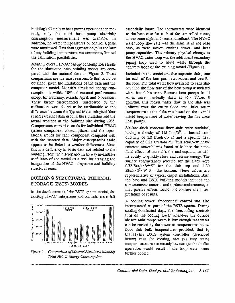
2~ Comparison ofMetered Simulated MonthlyTotal HVAC Energy Consumption
BUILDING STRUCTURAL THERMALST RAGE (BSTS) MODEL
essentially intact The thermostats were identicalto the base case for each of the controlled zones,as was zone night and weekend setback. The HVACwater loop flow rate was the same as in the basecase, as were boiler, cooling tower, and heatpump capacitieso The primary physical change tothe HVAC water loop was the additional secondarypiping loop used to route water through theconcrete floor of the building model (Figure 1).
Included in the model are five separate slabs, onefor each of the four perimeter zones, and one forthe corea The total water flow available to each slabequalled the flow rate of the heat pump associatedwith that slab's zone.. Because heat pumps in allzones were nominally sized at 370 ft2/ton, 3gpm/ton, this meant water flow to the slab wasuniform over the entire floor area. Inlet watertemperature to the slabs was based on the overallmixed temperature of water leaving the five zoneheat pumps..
Six...inch-thick concrete floor slabs were modeled,having a density of 145 Ibm/ft3, a thermal conductivity of 1..0 Btu/h·ft· o~ and a specific heatcapacity of 0.21 Btu/lbm.oR This relatively heavyconcrete material was found to balance the beneficial effects of the slab's thermal capacitance withits ability to quickly store and release energy. Thesurface conductances selected for the slabs were0.72 Btu/heft2eoF for the slab top and 1.00Btu/heft2eop for the bottom. These values arerepresentative of typical carpet installations.. Boththe base and BSTS building models included thesame concrete material and surface conductances, sothat passive effects would not confuse the interpretation of resultse
A cooling tower "freecooling" control was alsoincorporated as part of the BSTS systemo Duringcooling-dominated days, the freecooiing controlsturn on the cooling tower whenever the outsideair wet bulb temperature is low enough that watercan be cooled by the tower to temperatures belowfloor slab bulk temperatures--provided, that is,that (1) the BSTS system controller (describedbelow) calls for cooling, and (2) loop watertemperatures are not already low enough that boileroperation would result if the loop water werefurther cooled.
Si
'"
k:
:;: 100000]I:~
~ 60000IS:::JY)
§ 40000Q
~ 20000I41c:W 0
c:o
80000
building's 97 unitary heat pumps operate independently, only the total heat pump electricityconsumption measurement was available.. Inaddition, no water temperatures or control signalswere monitored. This data aggregation, plus the lackof any building temperature measurements, limitedthe calibration possibilitiesa
Monthly overall HVAC energy consumption resultsfor the simulated base building model are compared with the metered data in Figure 2.. Thesecomparisons are the most reasonable that could beobtained, given the limitations of the data and thecomputer modela Monthly simulated energy consumption is within 10% of metered performanceexcept for February, March, April, and November41These larger discrepancies, unresolved by thecalibration, were found to be attributable to thedifference between the 1YPical Meteorological Year(1MY) weather data used in the simulation and theactual weather at the building site during 1985..Comparisons were also made for individual HVACsystem component consumptions, and the operational trends for each component compared wellwith the metered data~ Major discrepancies againappear to be linked to weather differences.. Sincethis is a deficiency in basic data not related to thebuilding itself, the discrepancy in no way invalidatesusefulness of the model as a tool for studying theintegration of the HVAC subsystems and buildingstructural mass..
Commercial Data, Design, and Technologies 3.. 147
jan feb mar apr may jun jul aug sep oct nov dec
Mon1:h of Year
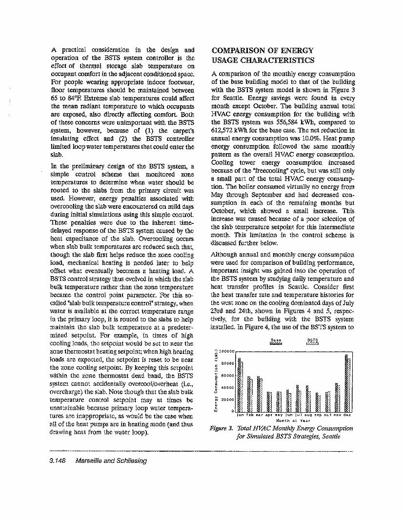
3. Total HVAC Monthly Energy Consumptionfor Simulated BSTS Strategies, Seattle
COMPARISO OF ENERGYUSAGE CHARACTERISTICS
A comparison of the monthly energy consumptionof the base building model to that of the buildingwith the BSTS system model is shown in Figure 3for Seattle. Energy savings were found in everymonth except October.. The building annual totalHVAC energy consumption for the building withthe BSTS system was 556,584 kWh, compared to612,572 kWh for the base case.. The net reduction inannual energy consumption was 10..0%.. Heat pumpenergy consumption followed the same monthlypattern as the overall HVAC energy consumption..Cooling tower energy consumption increasedbecause of the "freecoolingtt cycle, but was still onlya small part of the total HVAC energy consumption.. The boiler consumed virtually no energy fromMay through September and had decreased consumption in each of the remaining months butOctober, which showed a small increase.. Thisincrease was caused because of a poor selection ofthe slab temperature setpoint for this intermediatemontho This limitation in the control scheme isdiscussed further below&
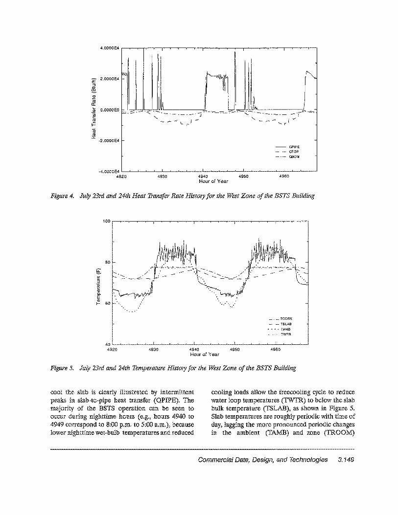
Although annual and monthly energy consumptionwere used for comparison of building performance,important insight was gained into the operation ofthe BSTS system by studying daily temperature andheat transfer profiles in Seattle. Consider firstthe heat transfer rate and temperature histories forthe west zone on the cooling dominated days of July
rd and 24th, shown in Figures 4 and 5, respectively, for the building with the BSTS systeminstalledo In Figure 4, the use of the BSTS system to
r.;
~
~ 100000]I:~
-:;. 60000E:JCi)
~ 40000o
~ 20000QI
CW 0
co
80000
A practical consideration in the design andoperation of the BSTS system controller is theeffect of thermal storage slab temperature onoccupant comfort in the adjacent conditioned space..For people wearing appropriate indoor footwear,floor temperatures should be maintained between65 to 84°R Extreme slab temperatures could affectthe mean radiant temperature to which occupantsare exposed, also directly affecting comfort. Bothof these concerns were unimportant with the BSTSsystem, however, because of (1) the carpet'sinsulating effect and (2) the BSTS controllerlimited loop water temperatures that could enter theslab..
In the preliminary design of the BSTS system, asimple control scheme that monitored. zonetemperatures to determine when water should berouted to the slabs from the primary circuit wasused. However, energy penalties associated withovercooling the slab were encountered on mild daysduring initial simulations using this simple control.These penalties were due to the inherent timedelayed response of the BSTS system caused by theheat capacitance of the slabe Overcooling occurswhen slab bulk temperatures are reduced such that,though the slab first helps reduce the zone coolingload, mechanical heating is needed later to helpoffset what eventually becomes a heating load.. ABSTS control strategy thus evolved in which the slabbulk temperature rather than the zone temperaturebecame the control point parameter.. For this so-
"slab bulk temperature control" strategy, whenwater is available at the correct temperature rangein the it is routed to the slabs to helpmaintain the slab bulk at a predeter-mined For in times of
the would be set to near thezone thermostat heating setpoint; when high heatingloads are expected, the setpoint is reset to be nearthe zone cooling setpoint.. keeping this setpointwithin the zone thermostat dead band, the BSTS
cannot overcoo1!overheat (i.e..,overCharge) the slab. Note though that the slab bulk
control setpoint may at times beunattainable because primary loop water temperatures are inappropriate, as would be the case whenall of the heat pumps are in heating mode (and thusara.W1IU! heat from the water loop)"
3e 148 Marseille and Schliesing
€ 2.0000E4::J
~(1)
«i0:~ O.OOOOEO
~~
t=ro(1)
:::t:-2.0000E4
,---- -------r---=" - l-v'- - ....... r
- OPIPEaropceOM
49604940 4950Hour of Year
4930-4.0000 E4 L...-....i---...I..-...L.--'--...1---.L.....-...L--.L---L--.L..-.L.-...L.--&.~---lI--I.-..a...........J-..J.....-....I.-.....I.--l----'--.........J
4920
4. July 23rd and 24th Heat Transfer Rate History for the H'lest Zone ofthe BSTS Building
80
~CD:.seCDC'.:'.LE<P
60I-
.- TeORE
TSLAB
~ .... " TAMB
-TWTR
49604940 4950Hour of Year
4930
40 Io........-.L-.......J--....-L-....A---.JI.----"----Jl---..A.---l---il----A-----A.----I.-----I "---~..l.._..._~.....J."".........l...____J._.........L.____I._.__Jl
4920
5. July 23rd and 24th Temperature History for the ~st Zone of the BSTS Building
cool the slab is clearly illustrated by intermittentin slab-to-pipe heat transfer (QPIPE)3 The
of the BSTS operation can be seen tooccur during nighttime hours (e.g., hours 4940 to4949 correspond to 8:00 porn. to 5:00 a.m..), becauselower nighttime wet-bulb temperatures and reduced
cooling loads allow the freecooling cycle to reducewater loop temperatures (TWTR) to below the slabbulk temperature (TSLAB), as shown in Figure 5.Slab temperatures are roughly periodic with time ofday, lagging the more pronounced periodic changesin the ambient (TAMB) and zone (TROOM)
Commercial Data, Design, and Technologies 3.149
temperatures because of the slab's thermal capacitance.. Irregularities in the slab temperature historyare caused by the BSTS system..
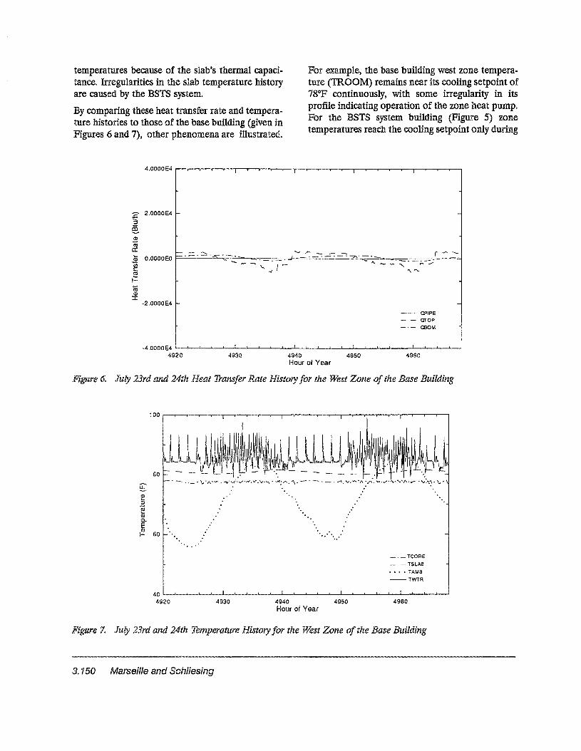
By comparing these heat transfer rate and temperature histories to those of the base building (given inFigures 6 and 7), other phenomena are illustrated..
For example, the base building west zone temperature (TROOM) remains near its cooling setpoint of78°P continuously, with some irregularity in itsprofile indicating operation of the zone heat pumpoFor the BSTS system building (Figure 5) zonetemperatures reach the cooling setpoint only during
:2 2.0000 E4 f-.......:'J
§,
f-- - -.....~ O.OOOOEO f-- - - - - -.A::" -_--...:. -,.,. _
~ ~~J-t'tS.=«i<])
:r.:-2.0000E4 f-
....., ""': _-= -=-= _-: ""?.__ ~ _ r ..r- .:-:
--- I\. __- '" ~-;;.. ",-
'\.""'-
- OPIPE- - mop
OBOM
-4.0000 E4 __""---...r.-.-'l--.....a...-....,.lI,I----.l~"__.............I.._...J_'-I-..--I.-.I.---I""--'Io--.l.-...--'----'--......&....--.a.'----'_"---"""'--'
4920 4930 4940 4950 4960Hour of Year
60 July 23rd and 24th Heat Transfer Rate History for the ~st Zone of the Base Building
80
~(1)
:5eCD0..E(J.)
60I-
___ TeaRE
- - TSLABII. II II TAMB
--TWTR
49604940 4950Hour of Year
493040 1o--.............J..-..a..-.....A...-..............--a.-............-.s.--.s............&....-4---i-............L.-.I.----'''''--II--.l.-...-..B.--'---'-----...a.---........
4920
7.. July 23rd and 24th Temperature History for the ~st Zone of the Base Building
3. 150 Marseille and Schliesing

portions of occupied hOUIS, clearly showing that theuse of the BSTS system reduces total heat pumpoperation9 The slab temperature history for the basebuilding (TSLAB in Figure 7) shows none of theirregularities found for the BSTS building, butinstead is smoothly periodic with time of day at atemperature that is also consistently higher than thezone9 Because of this higher temperature, the slabcontributes to the cooling load during occupiedhours (QTOP and QBOM in Figure 6), in contrastto the slab in the BSTS system (QTOP and QBOMin Figure 4).
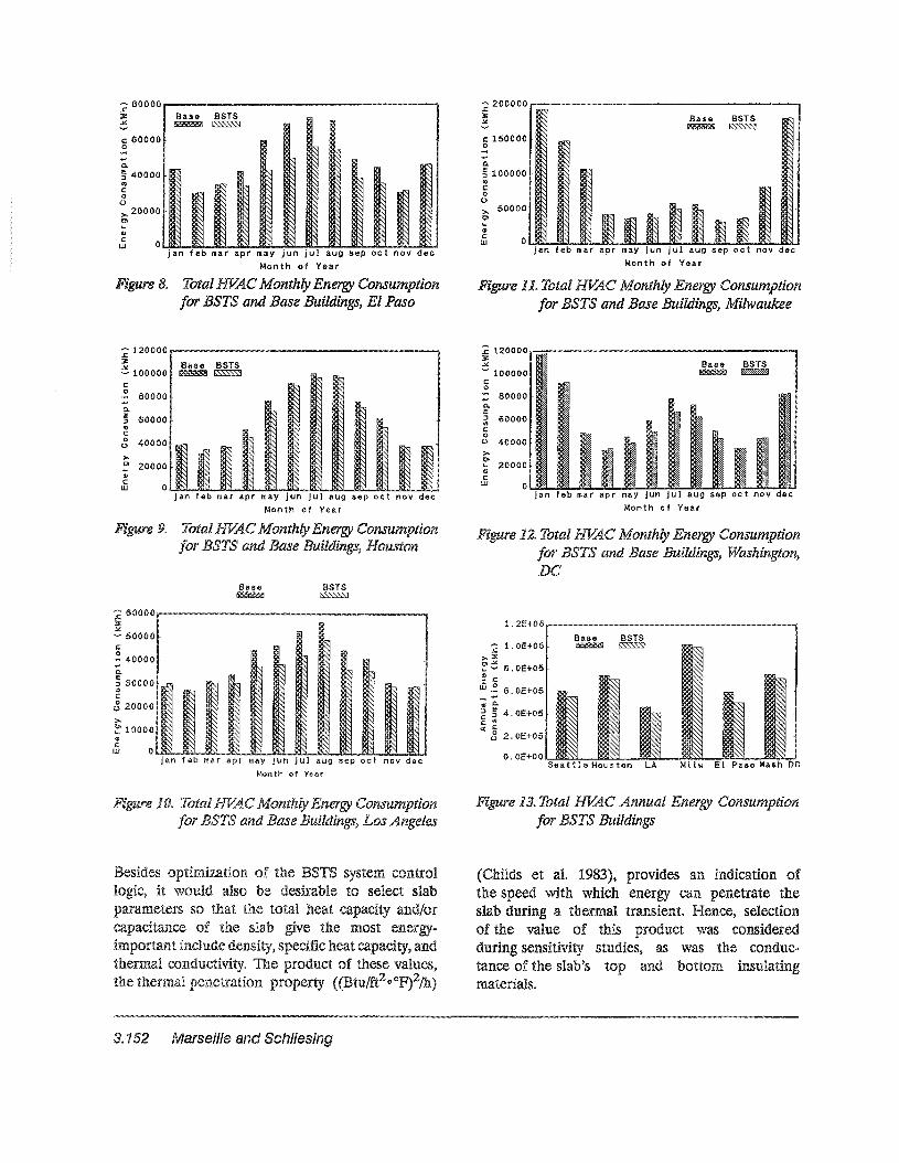
Additional simulations modeling the same buildingwere performed using 1MY weather data from fiveadditional cities: El Paso, Houston, Los Angeles,Milwaukee, and Washington D.Cu These cities werechosen because of their unique climatic conditionswhen compared to the temperate climate found inSeattleo Thgether, these cities typify fairly well therange of climatic conditions found across the U.S"Thus, performing the simulations in each of theselocations provided some quantitative insight as towhere a BSTS system can be most effectivelyapplied$
Figures 8 through 12 compare the simulated totalHVAC monthly energy consumption for the basebuilding in each of the five additional test locationsto that of the same building with the BSTS system~
In Figure 13, the total HVAC annual energy consumption is compared for all locations, includingSeattle.. The energy...conserving effects of the BSTSsystem were found to be most pronounced in warm,dry climates.. Annual energy savings in El Paso andLos Angeles were 18$6% and 12..7%, respectively..Although also a cooling dominated climate,Houston fared poorly, with annual energy savings of
4..9%, because the generally higher wet-bulbtemperatures in this location limited the coolingtower freecooling effect Energy savings in Washington were also lower due to its longer winter andhigh summer wet-bulb temperatures" The BSTSsystem provided little benefit during cold wintermonths because no "freeheating" source was available and core cooling-load requirements for the testDUlllQt:nfl 'weJre small. Improvements in annual energyconsumption in Milwaukee were thus quite limited(2&4%)0
Simulation results indicated the BSTS system has nodiscernible effect on summer/winter peak electricaldemands for the test building in any of the climateregions. On summer days, the BSTS system onlyserved to reduce morning heat pump operation,both because of the limited thermal capacity anddelivery capabilities of the slabs, and because thehigher afternoon wetbulb temperatures meant thecooling tower's freecooling effect could not beutilized. Further, because there is no comparable"freeheating" source, the winter peak demand thatoccurs during morning warmup was found to beunaffected by the BSTS system.
BSTS SYSTEM OPTIMIZATIONCONSIDERATIONS
The simulations reported above were made usingonly a single value for each of the summer andwinter BSTS slab bulk temperature control setpoints, with a preselected changeover betweenthe two setpoints in the spring and fall. In fact,for a truly optimized system the control setpointswould probably be varied on a monthly, daily,or even hourly basis because of widely varyingweather conditions, particularly during fall andspring times$ On cooling load dominated days,knowing precisely how far to cool the slabs whilestill avoiding overcooling could greatly improvesystem performance. The impact such an adaptivelpredictive control algorithm might have on systemperformancewas therefore examined.. The procedureentailed iteratively determining optimal setpoints for "average" days of each month of theyear through an extensive series of short parametric simulations, using knowledge of each day'sweather to help make "smart" control setpointdecisions manually.. Results indicated significantadditional savings could be obtained on some days,suggesting that development of a control algorithmthat dynamically controls BSTS slab bulktemperature setpoints based on predicted buildingloads and past performance would be highlybeneficial.. For example, extrapolation ofthese average day results for EI Paso suggestedannual energy savings as high as 30% might beobtainable.
Commercial Data; Design; and Technologies 3.151
Base BSTS~~
....Q.
5100000 .4')
coo>- 50000o'-<»
~ OUl::t.~c..J....~...._IQ~~~~~~~ .........~~""*--J~jan feb mar apr may jun jul aug sep oct nov dec
Month of Year
:c 200000...._---------------...........,~:4.
c: 150000o
O~~i4.iJ-....IiiLJ.-M~~~~~~~~~~~~jan feb mar apr may jun jul aug sap oct nov dec
Month of Year
.........0.
5 40000 .0')
c:oo>. 200000)
'-(J)
c:W
- 800001l""""""'--..........,"""""""'...........------------..........,.c~ Base BSTS~ ~lS'SSSS."S]
c: 60000o
Figure 11 Total HVAC Monthly Energy Consumptionfor BSTS and Base Buildings, El Paso
Figure 11" Total HVAC Monthly Energy Consumptionfor BSTS and Base Buildings, Milwaukee
jan feb mar apr may jun jul aug sap oct nov decMonth of Year
Jan feb mar apr may jun jut aug sap oct nov decMonth of Year
88T8~
60000
40000
.... 80000Q.E:Jtl)
c:o
<.>
:c 120000~!""""""" ...........--"""""""'-"""""""'--------...,~JiI!
- 100000co
>-~ 20000CDcw
Base BSTS~~
~
~~~
I t' ~I
~ 120000JJ:
~ 100000c0
80000....0.e 60000:JEI)
c:0 400000
>-D 20000'-Glc:
0UJ
9" Total HVAC Monthly Ene ConsumptionBSTS and Base Buildings, Houston
12. Total HVAC Monthly Energy Consumptionfor BSTS and Base Buildings, Washington,DC
() • OE+OO '-s..5ila a2.t~tl......le-H-lI:ollflLus~t.l-o-n ~L~A::l...--lMQCi~l wl.l..-E~I~Pa....s-o-:-W~a~sh~DC
1.2E+06_---------------,
'2 1.0E+06.;>.:1:
~ ~ 8.0E+05e c:
Jj.~ 6.0E+05_....~ Q.
E§ 4.0E+05c ~ol( c
8 2.0E+05
~ 60000_--.........,..."..".".",-...........-----__..............,.,...,,~Jl:..'I(
- 50000c:
; 40000-0.
5 30000$?c:tS 20000
>-~ 10000<»cW O~~~~~~~
jan feb mar apr may Jun Jul aug sap oct nov decMonth of V*~r
10$ Consumptionfor BSTS and Base Buildings, Los Angeles
13. Total HVAC Annual Energy Consumptionfor BSTS Buildings
Besides VVll...a.aJ1.AJl4.4U'-AV.m.& of the BSTS system controlit would also be desirable to select slab
oar'ameters so that the total heat capacity and/orof the slab give the most energy-
include heat capacity, and'VVJl.JB.""-l\.y:...... Ii..BI.lI".m.'-y. The product of these values,
property {(Btu/ft2@ oF)2/h)
(Childs et at 1983), provides an indication ofthe speed with which energy can penetrate theslab during a thermal transient. Hence, selectionof the value of this product was consideredduring sensitivity studies, as was the conductance of the slab's and bottom insulatingmaterials.
3. 152 Marseille and Schliesing

Future work must address the potential cost andenergy effectiveness of the BSTS system in the testbu· · g as well as other building designs, so thatdesigners and owners will be able to determinewhether integrating the HVAC subsystems with thebuilding mass makes sense for their needs"
REFERENCES
Andersson, KG.. Bernander, Be> Isfalt, andAH4' Rosenfeld6> 1979" Storage ofHeat and Coolth inHollow-Core Concrete Slabs. Swedish Experience andApplication to Large, American Style Buildings"Lawrence BerkeleyLaboratory, Berkeley, california..
Braun, I..E. 1990.. "Reducing Energy Costs and PeakElectric Demand Through Optimal Control ofBuilding Thermal Storage." ASHRAE Transactions,Vol.. 96, Pt 10
Childs, G.E.. and EoL$ Bales. 1983..Thermal Mass Assessment; An Explanation of theMechanisms which ilding Mass InfluencesHeating and Cooling Energy Requirements..ORNL/CONF-97, Oak National Laboratory,Oak Thnnessee"
and B. Crimmin. 1986.. CommercialHourly End...Use Study Status Report 1982 ... 1985.Seattle ashington
RJ~ Wallin, S~A
and D..B4' 19896> Initial Findings: TheIntegration of Water Loop Heat Pump and BuildingStructural Mass Storage Systems.. PNL...6751, PacificNorthwest Richland, Washington..
J"Vi and S.A Klein.. 1990.."Use of Thermal Mass to Offset CoolingLoads.."ASHRAE Transactions, Vol.. 96, Pt I ..
Solar Laboratory" 19836> A Transient SystemSimulation Program, Version 12"1,, University ofWisconsin-Madison4'
'\lll.lkoiHoi,,~'IIl" A 1976~ "A Fresh Look at the Calculationof Performance of Cooling Thwers." ASHRAETransactions $ Vol. 82, Pt 1, pp.. 269-28241
Iml)ra(~ticaI forL11l n'"'lihlr-n'il'''Ili' additional
.t"'\.'n1r'i-Mr"l"af'lll'''Il1l'''t''ll' the slab
basis, anwould be
demands"
The BSTS system was found to be an energyconserving system for the building modeled in thisstudy when compared to an identical buildingwithout the BSTS system" Annual energy savingsranged from approximately 2~4% to 18..6%, depend-
on climate$ The BS system performed bestweather data for the moderate, drier climates
of Los Angeles and EI where cooling-loads atlower ambient wet-bulb dominateOU1101IU! HVAC use" More modestsavings were obtained in YVf;4Il..lo.l!.'V'll
wa:smJ112t'on, D"C~ Little gain in annualllJ'_&&.'lU'A.UJI._JU'~
using Milwaukee weather data$to some conventional thermal storage
svs1temlS.. the BSTS was also found to havenej]~11f!]lDle effect on electrical
CONCLUSIONS
In general, it was found that selection of amore massive slab could improve overall energysavings during cooling-load dominated months,as it maximized the thermal capacitive benefitsof the BSTS system.. For example, a larger amountof incident solar loads could be absorbed into amore massive slab throughout the day, and theneffectively be purged from the building at nightusing the tower freecooling cycle.. However,economic and structural considerations wouldprobably impose practical limits on the slab massin an actual application" Increasing the conductanceof slab insulating materials was found to diminishthe beneficial thermal lag of the slab, and was thusnot pursued41
invaluable..
Commercial Data, Design, Technologies 3. 153