Embed Size (px)
Citation preview
1
The interactive bending wrinkling behaviour of inflated
beams
Y. P. Liu1, C. G. Wang1, 2, H. F. Tan1, 2, M. K. Wadee3
1Center for Composite Materials, Harbin Institute of Technology, Harbin, 150001,
China
2National Key Laboratory of Science and Technology on Advanced Composites in
Special Environments, Harbin Institute of Technology, Harbin 150080, China.
3College of Engineering, Mathematics and Physical Sciences, University of Exeter,
North Park Road, Exeter, Devon EX4 4QF, United Kingdom.
Abstract
A model is proposed based on a Fourier series method to analyse the interactive
bending wrinkling behaviour of inflated beams. The whole wrinkling evolution is
tracked and divided into three stages by identifying the bifurcations of the equilibrium
path. The critical wrinkling and failure moments of inflated beam are then able to be
predicted. The global-local interactive buckling pattern is elucidated by the proposed
theoretical model and also verified by non-contact experimental tests. The effects of
geometric parameters, internal pressure and boundary conditions on the buckling of
inflated beams are investigated in the end. Results reveal that the interactive buckling
characteristics of inflated beam under bending are more sensitive to the dimensions of
the structure and boundary conditions. We find that beams which are simply
supported at both ends or clamped and simply supported boundary conditions may
prevent the wrinkling formation. The results provide significant support for our
Corresponding author E-email: [email protected]

2
understanding of the bending-wrinkling behaviour of inflated beams.
Keywords: Inflated beam; Bending wrinkling; Wrinkling evolution; Interactive pattern;
Fourier series method
1. Introduction
As one of the most typical membrane-like structures, inflated beams have been
the subject of interest in recent years owing to their distinctive features. They are of
much lower weight and cost, can be folded easily and deployed quickly. Hence, they
are widely applied to terrestrial and aerospace structures [1]. However, an inflated
beam is a typical thin-wall structure and the instability phenomena, including global
buckling, local wrinkling or both, may easily occur [2, 3]. Investigations on the
instability phenomena of these structures can be categorized into two categories:
global buckling analysis and local wrinkling analysis.
The global buckling, as its name suggests, analysis mainly focuses on a global
buckling mode and critical buckling load. Euler-Bernoulli’s kinematics was widely
adopted because of its simplicity and ability correctly to determine the structural
response in many practical situations. Pioneering work was carried by Comer and
Levy [4] who provided analytical expressions for the deflection in an inflated
cantilever beam by means of Euler-Bernoulli’s kinematics. Then, Main et al. [5]
conducted experiments on cantilever inflated beams and compared the results with
Comer and Levy’s theory [4]. Suhey et al. [6] considered a pressurized tube under
uniformly distributed load in ocean aquaculture and theoretical results were obtained
assuming Euler-Bernoulli’s kinematics as well. However, this theory did not consider

3
shear and inflation pressure effects on inflated beams. In order to improve the
previous formulations, many other authors preferred to use the Timoshenko beam
theory which is more appropriate for thin-walled beams. Fichter [7] published a paper
in which the internal pressure appears in the deflection expression based on the
minimization of total potential energy. By taking into account the deformed state of
the beam, Wielgosz and Thomas [8, 9] gave analytical expressions for inflated beams
and panels using Timoshenko beam theory. In their approach, the force generated by
internal pressure was treated as a follower force which accounted for pressure
stiffening effects. Le van and Wielgosz [10] improved Fichter's [7] theory by using
the principle of virtual work in the context of the total Lagrangian formulation and
proposed solutions for the bending and buckling of an inflated tube. Davids and
Zhang [11] developed Fichter's [7] results by considering the pressure work during the
volume change in isotropic Timoshenko beams and accounted for fabric wrinkling via
a moment-curvature nonlinearity. Apedo et al. [12] developed efficient numerical
techniques for predicting the nonlinear load–displacement response of inflated
beams by proposing a 3D Timoshenko beam with a homogeneous orthotropic woven
fabric. Barsotti and Ligarò [13] assessed the nonlinear elastic response of an inflated
cylindrical beam through a simple mechanical model. The geometrical nonlinearities
in the model due to both the cross-sectional ovalization and wrinkling were carefully
considered.
Distinct from the global buckling analysis, local wrinkling is assumed to occur
when the maximum compressive stress reaches the uniform compression critical value

4
for a circular tube. Three models are used to describe the wrinkling of the inflated
beam: the membrane model, the thin-shell model and the shell-membrane model.
Haugthon and McKay [14] adopted the membrane model to predict the wrinkling
characteristics of the inflated beam where the wrinkles occurred when the axial
compression reached zero. In the membrane model, both the wrinkling and the
collapse moments are independent of the material properties, and are only related to
the structural cross-section size and inflation pressure. Then, Veldman [15] regarded
the inflated beam as a thin-shell and predicted the wrinkling and collapse moments
utilizing the buckling critical load of a shell. In fact, the membrane and thin-shell
models correspond to two perfect states respectively which are different from
experimental results [16-18]. Therefore, Wang et al. [18] proposed a shell-membrane
model using a modified factor based on the membrane and thin-shell models.
Compared with previous models, the shell-membrane model showed a better
correlation with the experimental results in predicting the wrinkling and collapse
loads of inflated beams.
Inflatable structures do have additional stiffness which comes from initial
pressure, but do not contain the stiffness that comes from material and shape. Both
buckling and wrinkling mean a deformation process in which a structure subjected to
high compressive stress undergoes a sudden change in morphology at a critical load.
When the beam is compressed axially, beyond a certain critical load it spontaneously
bows outwards, which is called global or Euler buckling. Compared to global
buckling, characteristics of local wrinkling are wavelike and periodic. The above

5
review of literature indicates that the global buckling analysis focuses on the
prediction of global buckling characteristics, such as the critical bifurcation and
collapse loads, the wrinkling region and the buckling mode. In contrast, the local
wrinkling analysis focuses on the local wrinkling characteristics, such as the
wrinkling amplitude, the wrinkling wavelength, the wrinkling number and the
wrinkling configuration. Furthermore, most of the experiments on the instability
phenomena concentrate on the detection of the global buckling characteristics [19, 20]
or of the local wrinkling characteristics [21]. Few papers focus on both of these
features in theoretical or experimental studies. Consequently, there is a need to
develop theoretical and experimental methods for describing the instability
phenomena that couples global and local wrinkling characteristics. A Fourier series
method, which corresponds to the periodic and sinusoidal characteristics of wrinkles
correctly, is able to account for instability phenomena, such as bending instabilities of
circular tubes [22, 23], buckling of sandwich structures [24] or of a Winkler
foundation beam [25].
In this paper, the Fourier series method is introduced to the Fichter's [7] theory to
derive a Fourier model which can characterize the interactive bending wrinkling
behaviour of inflated beams. The non-linear governing equations of the Fourier model
are then solved by a Newton trust region method [26]. The whole wrinkling evolution
is tracked using the proposed model and the predicted buckling patterns are verified
by the non-contact experimental tests. Finally, the effects of geometric parameters,
internal pressure and boundary conditions on the buckling of inflated beam are

6
investigated
2. Methodology
2.1 Classical model of inflated beam
Fig. 1. Schematic represenation of the inflated beam, beam, defining axes, dimensions and
displacements.
Inflated beams are considered to be thin-walled cylinders which depend on
internal pressure for much of their load-carrying ability as shown in Fig. 1. The axial
displacement (in the x direction), transverse displacement (in the y direction) and
rotation angle about the z axis are represented by u , v and , respectively. The
parameters L, r and t are respectively the length, cross-sectional radius, and wall
thickness of the inflated beam. In-plane means that a steady moment M is applied
on each end of the beam about the x-axis. According to Fichter's [7] theory,a system
of equilibrium equations can be obtained from the principle of virtual work following
the Timoshenko model:
0str pres ext (1)
where str and ext represent the strain energy and external energy, respectively,
7
while pres represents the potential energy of the internal pressure due to
deformation. We make the simplification of neglecting the circumferential strain and
twist around the longitudinal axis and thus the strain energy str of the inflated
beam can be expressed as:
0
1
2
L
str N Mk S dx (2)
where , and k are respectively the axial, shearing and bending strain of the
inflated beam. Since the inflated beam is made from isotropic Polyurethane thin film,
the strains and the corresponding loads ( N , S , M ) are defined in Eqs. (3)-(4):
2, ,
,
,
1
2x x
x
x
u v
v
k
(3)
3
2N E rt
S G rt
M E r tk
(4)
where E and G are the elasticity and shear modulus, respectively. In addition, if the
inflated beam is usually made from fabric, Eq. (4) can be replaced by an orthotropic
constitutive equation to describe the orthotropic wrinkling behavior in principle.
However, in this manuscript, we make the simplification of neglecting the
circumferential strain in this Fourier model. Therefore, the expression of orthotropic
constitutive equation is almost similar to isotropic Eq. (4). The potential energy pres
is then given by:
2 2, ,0
1
2
L
pres x xp V p r u v dx (5)
where V is the change in enclosed volume due to deformation, p is the internal

8
pressure. In addition, the external work by the applied load ext is then given by:
1 2 30 0
LL
ext f u f v f dx Nu Sv M (6)
where 1f , 2f , 3f , N , M and S are the external applied loads.
2.2 Fourier model of inflated beam
The Fourier series method in this part is adopted to investigate the interactive
bending-wrinkling behaviour of the inflated beam. The deformation response of the
system is considered as the sum of a slowly-varying mean field and a nearly periodic
fluctuation. All the unknowns in Section 2.1 are written in the form of Fourier series:
( ) ( ) ijqxj
j
U x U x e
(7)
where ( )U x is the unknown field which contains functions u , v and . The
Fourier coefficients ( )jU x represent the envelope for the jth harmonic, and the
coefficients of the zeroth harmonic are real while the others are complex. The
frequency q is defined as q nL
, where n is the wavenumber.
The Fourier coefficients ( )jU x vary slowly and are assumed to be constant over
a period , 2 /x x q . Several calculations have been proposed by Damil and
Potier-Ferry [27] to manage the Fourier coefficients. If ( )a x and ( )b x are Fourier
series with slowly varying Fourier coefficients as in Eq. (7), the following identities
hold:
0 0
( ) ( ) ( ) ( )L L
j jj
a x b x dx a x b x dx
(8)
, ,( ) ( )x j j j x jj
da da ijn a a ijna
dx dx L L
(9)

9
22
2 2, , ,2
( ) ( ) 2xx j j j xx j x j
j
d a da ijn a a ijna j n a
dx dx L L L
(10)
1 1
1
( ) j j j jj
ab a b
(11)
By applying the above identities to Eqs. (3)-(4), the force and strain fields of the
new Fourier model are obtained as follows:
1 1
1
1 1
1( ) ( ) ( ( ) )
2j j j j jj
d d djin u j in v j j in v
dx L dx L dx L
(12)
( )j j
dk jin
dx L
(13)
( )j j j
djin v
dx L
(14)
2j jN E rt (15)
j jS G rt (16)
3j jM E r tk (17)
In the same way, the strain energy and potential energy can be expressed as:
0
1( )
2
L
str j j j j j jj j j
N M k S dx
(18)
2
0
1[ ( ) ( ) ]
2
L
pres j j j j jj j j
d dp r ijn u ijn v dx
dx L dx L
(19)
Of course, a more refined picture could be constructed by the inclusion of more
Fourier terms, which would also results in a correspondingly more complex and
difficult task to ensure numerical convergence. We consider just three envelopes ( j =
-1, 0, 1) as these are sufficient to reveal interactive buckling phenomena. 0U is
identified as the mean value and represents the global deformation, while 1U , which
is conjugated with 1U , represents the amplitude of fluctuation for the local wrinkling.
Then the energy can be expressed as:

10
2 2 22 3 2 20 1 0 1 0 10
1 1 1[2 ( ) ( ) ( )]
2 2 2
L
str E rt E r t k k G rt dx (20)
0, 1 1 0, 0
2
022
1 1 1 1 0 1
1
2
x xL
pres
d du in u in u v
dx L dx Lp r dx
d din v in v
dx L dx L
(21)
where the strains in the Fourier model are expressed as:
2
2 2 20 0, 0, 1, 1
1
2x x xu v v n vL
(22)
1 1, 0, 1, 1( )x x xu v v invL
(23)
0 0,xk (24)
1 1
dk ijn
dx L
(25)
0 0, 0xv (26)
1 1 1( )d
ijn vdx L
(27)
As expected, Eqs. (20)-(21) include the mean field 0U and the amplitude of the
fluctuation 1U , which depicts the interactive instability of the inflated beam. On the
other hand, the term 20, 0,
1
2x xu v in Eq. (22) corresponds to the global strain and the
last term 2
2 21, 1xv n v
L
corresponds to local wrinkling. Meanwhile, the last term is
always positive, which implies a decrease of the compressive strain due to local
wrinkling. If the beam is in a compressive state, a local instability can occur and these
two terms lead to a reduction of compressive stress. Hence, the Fourier model here
permits a description of the stress release due to local buckling. Different from the
classical expression of strain, the term 2
21n v
L
represents the wrinkling strain
which is consistent with the Calladine’s [28] results.
11
In this paper, the wrinkling behaviour of inflated beam is studied under pure
bending: moments are applied at both ends of the beam. As there is no applied
external axial force and the applied moments are constant, the assumptions
0( ) ( )u x u x , 0( ) ( )x x , are taken into account, which means the longitudinal
displacement and rotation angle do not fluctuate. Here, the research focus is on the
interactive global-local instability configuration and not on phase modulation.
Therefore, a further approximation is to suppose that the envelope 1( )v x is real,
which only considers amplitude modulation and disregards the evolution of phase.
Then, the transverse displacement can be expressed as:
0 1( ) ( ) 2 ( )cos( )v x v x v x qx (28)
By substituting Eqs. (20)-(21) into Eq. (1), the final buckling governing equation
of the inflated beam can be deduced as:
0, 0x (29)
22 2
0 0, 0, 1, , 0, 1 , 0, 0 , 0,
1( ) ( ) ( ) 0
2xx x x x x x x x xEt v Etv v Et n v v Gt v prL
(30)
2 2 22 2
0 1, 0 1 0, 1, , 0, 1 1, 12 2 ( ) 0xx x x x x xxE v E n v Ev v E n v v Gv G n vL L L
(31)
20, 0, 0( )( ) 0xx xEr t Gt pr v (32)
2.3 Numerical implementation
The non-linear governing Eqs. (22), (29)-(32) are solved through an incremental
Newton-Raphson numerical procedure and enhanced to enable the tracing of
post-buckling equilibrium paths through a Newton trust region method [26]. In order
to apply this method, the quadratic model m should be considered at first:

12
1( ) ( )
2. .
T Tk k k k
k
m s f x g s B s
s t s
(33)
Here, kg is the gradient of the objective function ( )kf x at the current iteration point
kx . s is the unknown functions and the step size is required to be bounded by the trust
region radius k . Both the Cauchy point (the minimizer of m in the steepest descent
direction) and the Newton point are utilized. The incremental step is then given by a
combination of the Cauchy step with the Newton step, and the unknowns are
determined until the norm of the scaled residual is less than a given tolerance. The
computation is started by a damped Newton step. Here, the damping factor, which
determines the first Newton step, is set to 0.5 to ensure good convergence. Meanwhile,
an initial displacement imperfection is introduced as a geometric imperfection by
applying a very small out-of-plane displacement at the center to trigger global
buckling. The value of the displacement imperfection is 10-5, and the numerical
results show insensitivily to the initial imperfection as long as it is small enough (~
10-5-10-6), which is also demonstrated by others [17, 29].
3. Results and discussions
In this section, we will discuss interactive bending wrinkling behaviour of the
simply supported inflated beam under bending without restriction on axial
displacement ( 0u ). The interactive buckling characteristics will be obtained by
solving the governing Eqs. (22), (29)-(32) which include global deformation ( 0v ) and
local wrinkling ( 1v ) using the numerical method in Section 2.3. According to the

13
following experiments, the material and structural parameters of inflated beam are
listed in Table 1.
Tab. 1. Material and geometrical parameters
Parameters Magnitude
Length of the beam (L) 0.3 (m)
Young’s modulus of beam material (E) 2.0E8(Pa) Poisson’s ratio ( ) 0.3
Radius of the beam (r) 0.025(m)
Thickness of the beam (t) 5.0E-5(m)
Internal pressure (p) 5.0E3(Pa)
3.1 Theoretical prediction and experimental verification
The values of moment and deflection values are normalized by swM and
thickness t respectively, in order to be given in dimensionless terms. Here, the critical
wrinkling moment of shell model swM can be expressed as follows [16, 30]:
2
3
23 1sw
rEtM p r
(34)
Then, the dimensionless moment and deflection can be obtained as:
/ swm M M , /w v t (35)
Fig. 2(a) illustrates the deformation patterns of the inflated beam under two
different applied moments ( 0.37 and 0.93m ). It shows that the structure is
unstable when the applied moment is 0.37 and global bending deformation dominates
the pattern without any local wrinkles. As the applied moment increases to 0.93, local
wrinkling is observed and the buckling pattern is the typical interactive buckling
between the global bending deformation and local wrinkling. Fig. 2(b) shows a
magnified view of the local wrinkles regardless of the global deformation. As seen

14
from the diagram, local wrinkles distribute along the whole inflated beam and the
amplitude of these wrinkles is almost same except for those near the boundary.
Wrinkles at the edges are smaller than those in the middle owing to the boundary
conditions which restrict on the evolution of local wrinkles.
0.0 0.2 0.4 0.6 0.8 1.0-0.002
0.000
0.002
0.004
0.006
w (
105 )
Axial direction (m)
Fig. 2. The deformation patterns of the inflated beam under bending: (a) deformation patterns of
the inflated beam under different moments; (b) zoomed view of local wrinkles when the applied
moment is 0.93.
In order to verify the theoretical results, a non-contact testing scheme is proposed
to measure the buckling pattern of the inflated beam. In the experiment, an inflated
beam, which is made from polyurethane thin film, is fixed onto the bending test
apparatus (as shown in Fig. 3). The properties of polyurethane thin film are Young’s
modulus of 200MPa, Poisson’s ratio of 0.3 with 50μm thickness. The length and
cross-sectional radius are 0.942m and 0.025m, respectively. The bending moment is
carried out by rotating a support disk gradually. The buckling pattern is captured using
VIC-3D and T-Scan laser tracker instruments (as shown in Fig. 3). The global bending
deformation belongs to a macroscale and is captured using VIC-3D instrument based
on DIC (Digital Image Correlation) technique which is an effective and reliable
method to test the displacement field with an approving precision [31]. There are four
0.0 0.2 0.4 0.6 0.8 1.00.000
0.005
0.010
0.015
0.020 Global deformation+local wrinkling (M=0.93)
0.0 0.2 0.4 0.6 0.8 1.00.000
0.005
0.010
0.015
0.020
Global deformation (M=0.37)
Axial direction (m)0.0 0.2 0.4 0.6 0.8 1.0
0.000
0.005
0.010
0.015
0.020
Global deformation (M=0.93)
w (
105 )
b) a)
15
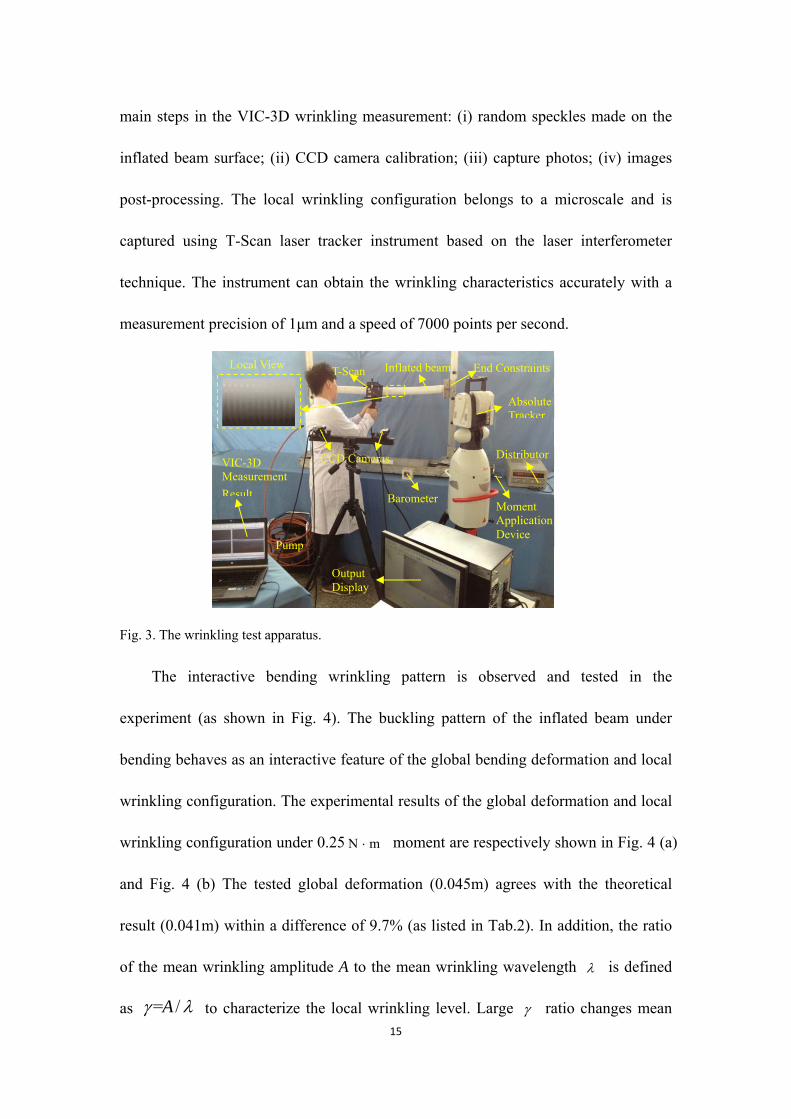
main steps in the VIC-3D wrinkling measurement: (i) random speckles made on the
inflated beam surface; (ii) CCD camera calibration; (iii) capture photos; (iv) images
post-processing. The local wrinkling configuration belongs to a microscale and is
captured using T-Scan laser tracker instrument based on the laser interferometer
technique. The instrument can obtain the wrinkling characteristics accurately with a
measurement precision of 1μm and a speed of 7000 points per second.
Fig. 3. The wrinkling test apparatus.
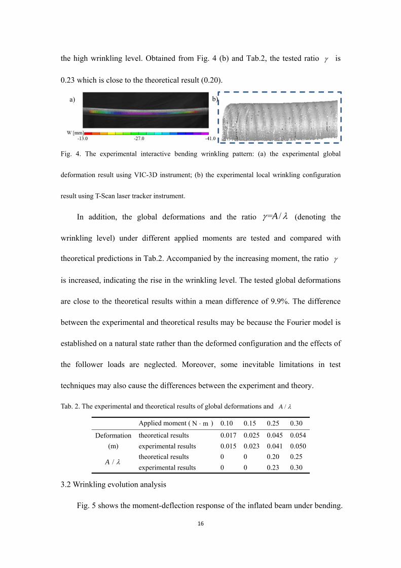
The interactive bending wrinkling pattern is observed and tested in the
experiment (as shown in Fig. 4). The buckling pattern of the inflated beam under
bending behaves as an interactive feature of the global bending deformation and local
wrinkling configuration. The experimental results of the global deformation and local
wrinkling configuration under 0.25 N m moment are respectively shown in Fig. 4 (a)
and Fig. 4 (b) The tested global deformation (0.045m) agrees with the theoretical
result (0.041m) within a difference of 9.7% (as listed in Tab.2). In addition, the ratio
of the mean wrinkling amplitude A to the mean wrinkling wavelength is defined
as = /A to characterize the local wrinkling level. Large ratio changes mean
Pump
T-Scan Inflated beam
Absolute Tracker
Output Display
CCD Cameras VIC-3D Measurement
Result Barometer
Distributor
End Constraints
Moment Application Device
Local View
16
the high wrinkling level. Obtained from Fig. 4 (b) and Tab.2, the tested ratio is
0.23 which is close to the theoretical result (0.20).
Fig. 4. The experimental interactive bending wrinkling pattern: (a) the experimental global
deformation result using VIC-3D instrument; (b) the experimental local wrinkling configuration
result using T-Scan laser tracker instrument.
In addition, the global deformations and the ratio = /A (denoting the
wrinkling level) under different applied moments are tested and compared with
theoretical predictions in Tab.2. Accompanied by the increasing moment, the ratio
is increased, indicating the rise in the wrinkling level. The tested global deformations
are close to the theoretical results within a mean difference of 9.9%. The difference
between the experimental and theoretical results may be because the Fourier model is
established on a natural state rather than the deformed configuration and the effects of
the follower loads are neglected. Moreover, some inevitable limitations in test
techniques may also cause the differences between the experiment and theory.
Tab. 2. The experimental and theoretical results of global deformations and /A
Applied moment ( N m ) 0.10 0.15 0.25 0.30
Deformation
(m)
theoretical results 0.017 0.025 0.045 0.054
experimental results 0.015 0.023 0.041 0.050
/A theoretical results 0 0 0.20 0.25
experimental results 0 0 0.23 0.30
3.2 Wrinkling evolution analysis
Fig. 5 shows the moment-deflection response of the inflated beam under bending.
a) b)
17
Observed from Fig. 5, there are two critical points which are named as the critical
wrinkling point (marked as A) and the failure point (marked as C). The critical
wrinkling load corresponds to the point where a nonlinear equilibrium path departs
from the initial linear one. The failure point is determined as the following
intersection between the bifurcation path and the primary path. Based on the critical
points in the equilibrium path, the wrinkling evolution can be divided into three stages,
which are named as I, II, III. Stage I (OA) is named as a pre-bucking stage and a
linear response characterizes the primary path. In this stage, without any local
wrinkles ( 1 0v ), global bending dominates the deformation pattern of the inflated
beam. The applied moment at the critical wrinkling point A is 0.78, which is at the
critical wrinkling moment wM . When the applied moment reaches wM , an obvious
bifurcation occurs at the point A and the primary path turns to the bifurcation path.
Then the wrinkling evolution goes into Stage II which is identified as the
post-buckling stage. The wrinkling strain (the last term in Eq. (22)), which has an
abrupt increase due to the local wrinkling formation, is adopted to reflect the first
bifurcation. The local wrinkling phenomenon appears in this stage and the pattern
characterizes as a typical interactive buckling between the global deformation and
local wrinkling. Note that the applied moment has slight effects on the structural
deflection in the initial postwrinkling stage (AB). From the view of the energy
equilibrium (Eq. (1)), the wrinkling strain energy offsets the increase of external
energy. Therefore, in this stage, the wrinkles grow in a relatively stable state and the
global bending deformation remains almost stable. In response to the increasing

18
applied moment, the global deformation and local wrinkling increases simultaneously,
which results in a continued monotonic increase in the moment-deflection curve (BC).
When the moment exceeds the failure point C (the failure moment 1.19fM ),
the wrinkles eventually localize and cause catastrophic failure in the form of sharp
local kinks (as shown in Fig. 5) which promotes the wrinkling evolution into the
failure stage (CD). Recall that the results of the Fourier model are obtained under the
assumption that the wrinkling configuration has a slow and nearly periodic fluctuation.
Thus, the assumption is invalid in the last stage due to the existence of sharp local
kinks.
Fig. 5. The numerical moment-deflection response of the inflated beam under bending.
3.3 Critical wrinkling moment and failure moment
In this part, the predicted critical wrinkling and failure moments are compared
with the results from previous models, including the membrane model [14], the
thin-shell model [15] and the shell-membrane model [18]. The comparisons (in Fig. 6)
show that the critical wrinkling (0.78) and failure moments (1.19) lie among the
results predicted by the shell and membrane models.
0.020
0.016
0.012
0.008
0.004
0.0001.851.481.110.740.37
D
C
BA
Failure point
Mf
Bifurcation point
FailurePost-bucklingPre-buckling
Bifurcation path
Primary path
III II
w (
105 )
m
I
MwO
0.0

19
In the Fourier model, the structural failure corresponds to the occurrence of sharp
local kinks before the wrinkles distribute around the whole cross-section of the
inflated beam. However, in the membrane and thin-shell models, the structure fails
when the wrinkling angle reaches 2 (the whole hoop wrinkles) which does not
comply with the practical case. Different from the membrane and thin-shell models,
the failure of the shell-membrane inflated beam occurs when the wrinkling angle
approaches 1.5 , which shows a better correlation with the experimental results and
the Fourier model.
0
1
2
3
4
5
6
7
w (
105 )
Membrane model Shell-membrane model Shell model
Wri
nkli
ng a
ngle
(ra
d)
m
0.020
0.016
0.012
0.008
0.004
0.0002.221.851.481.110.740.00
1.19
0.44 0.70 0.89
0.78
1.331.00
Fourier model
2
0.37
Fig. 6. The numerical critical wrinkling and failure moments from different models.
3.4 Internal pressure and structural size
The effects of the internal pressure and structural size on the wrinkling behavior
are carried out and shown in Fig. 7. The moment-deflection responses of the inflated
beam with 0.025m radius for different internal pressures are shown in Fig. 7 (a). The
increasing pressure results in a slight reduction of the deflection and a slight increase

20
of the critical wrinkling and failure moment. Specifically, for a 40% variation on the
assumed pressure of 5kPa, the critical wrinkling moment changes only by 9.52% and
the failure moment by 6.45%. It also shows that the critical wrinkling and failure
moments are proportional to the internal pressure due to the improvement of the
transverse shear stiffness, which is described by Eq. (32). This is in line with the
conclusions in the literature [8].
1.371.030.960.63
0.018
0.012
0.006
0.0001.11 1.480.740.37
0.921.07 1.30
1.190.78
0.67
w (
105 )
m
1KPa 3KPa 5KPa 7KPa 9KPa
0.00
2.701.19 2.330.78
0.25
w (
105 )
m
r=0.015 r=0.025 r=0.035
0.19
0.018
0.012
0.006
0.0000.00 2.960.74 1.48 2.22
Fig. 7. The numerical moment-deflection responses of the inflated beam with different internal
pressures and radii: (a) the moment-deflection responses with different internal pressures; (b) the
moment-deflection responses with different radiuses.
Fig. 7 (b) depicts the moment-deflection responses of the inflated beam with
internal pressure of 5kPa for different radii (0.015m, 0.025m and 0.035m). An
increasing radius results in a large reduction of the deflection and an obvious increase
of the critical wrinkling and failure moment due to the improvement of structural
stiffness. Specifically, the critical wrinkling and failure moments have a more than
three times improvement for a 40% increase on the assumed 0.025m radius. The
effects of radius on the critical wrinkling and failure moments are more significant
compared with the cases of internal pressure. In addition, for a slender inflated beam,
a) b)

21
the sharp local kinks appear quickly after bifurcation due to a slower bending stiffness
and a rapid wrinkling evolution. In such cases the inflated beam rapidly fail soon after
it is wrinkled.
3.5 Boundary conditions
Fig. 8 shows the buckling patterns with the same applied moment (0.25 N m )
under four cases with different boundary conditions: simply supported and sliding
simply supported (S-SL), simply supported and simply supported (S-S), clamped and
sliding simply supported (C-SL), clamped and simply supported (C-S) (note that we
refer to sliding which is sometimes elsewhere referred to as rolling). The results in Fig.
8 reveal that the buckling pattern of the inflated beam under bending is closely
relevant to the boundary condition. The symmetrical boundary conditions lead to a
symmetrical buckling pattern and the same situation is met for nonsymmetrical
boundaries.
Global deformation dominates the configuration under the S-S or C-S boundary
conditions and there is no wrinkle in these two cases. The configuration under the
S-SL or C-SL boundary condition behaves with a typical interactive pattern between
the global bending and local wrinkling. Compared with the other two boundary
conditions (S-S and C-S), the S-SL and C-SL boundary conditions have no
restrictions on the axial displacement ( 0u ) and allow the material to shrink along
the axial direction, which leads to an increase of wrinkling strain (the last term in Eq.
(22)).

22
Fig. 8. The buckling patterns under different boundary conditions predicted by Fourier model
( 0.93M ).
Conclusions
In this study, the Fourier series method is introduced to the Fichter's theory to
derive a Fourier model which can characterize the interactive bending wrinkling
behaviour of inflated beams. The whole wrinkling evolution can be tracked using the
proposed model and the predicted buckling patterns are verified by the experimental
tests. The bending wrinkling behaviour of the inflated beam is closely related to its
internal pressure, relative dimensions and boundary conditions. Several important
conclusions are drawn as follows.
The wrinkling evolution can be divided into three stages based on the critical
wrinkling point and the failure point in the equilibrium path. In the pre-buckling stage,
global bending dominates the deformation pattern of the inflated beam without any
local wrinkles and a linear response characterizes the primary path. In the
post-buckling stage, the local wrinkling phenomenon appears and the pattern
0.0 0.2 0.4 0.6 0.8 1.0
0.016
0.012
0.008
0.004
w (
105 )
Axial direction (m)
S-SL S-S C-SL C-S
0.000
S-SL S-S
C-SL C-S

23
characterizes as a typical interactive buckling between the global deformation and
local wrinkling. Finally, the formation of sharp local kinks transforms the wrinkling
pattern into the failure stage and accelerates the collapse of the structure.
In the Fourier model, the predicted critical and failure moments are respectively
0.78 and 1.19 and the failure wrinkling angle is amount to 1.52 . Moreover, the
effects of radius on the critical wrinkling and failure moments are more significant
than that of internal pressure. The buckling pattern is quite sensitive to the boundary
condition. A larger radius and internal pressure of the inflated beam with an S-S or
C-S boundary condition will be a desired consideration to control wrinkling
characteristics and evolution. In addition, the inflated beam is made from isotropic
polyurethane thin film in the experiment. Therefore, the isotropic constitute equation
is adopted here and the orthotropic mechanical behavior of inflated beam made from
fabric will be focused on investigation in the future.
Data accessibility
This work has no accompanying data.
Authors' contributions
Y.L. conceived the mathematical models, performed the experimental
measurements and drafted the paper. C.W. proposed the idea of the study, funded and
supervised the project. H.T. and M.K.W. revised the draft. All authors regularly
discussed the progress during the entire work.

24
Competing interests
We declare we have no competing interests.
Ethics
This work does not pose ethical issues.
Funding
This work is supported by National Natural Science Foundation of China,
11172079 and 11572099; Program for New Century Excellent Talents in University,
NCET-11-0807; Natural Science Foundation of Heilongjiang Province of China,
A2015002; the Fundamental Research Funds for the Central Universities,
HIT.BRETIII.201209 and HIT.MKSTISP.2016 29.
Ackowledgement
The support from NSF is gratefully acknowledged. The authors also would like
to thank four anonymous reviewers for their encouragement and helpful comments on
an earlier version of the paper.
Reference
1. Jenkins, C.H.M., 2001. Gossamer Spacecraft: Membrane and Inflatable Structures
Technology for Space Applications, vol. 191. American Institute of Aeronautics
and Astronautics, Reston, Virginia.
2. Jiao, R., Kyriakides, S., 2011. Ratcheting and wrinkling of tubes due to axial

25
cycling under internal pressure: Part I experiments. Int. J. Solids Struct. 48,
2814-2826.
3. Nguyen, T. T., Ronel, S., Massenzio, M., Jacquelin, E., Apedo, K. L., Phan-Dinh,
H., 2013. Numerical buckling analysis of an inflatable beam made of orthotropic
technical textiles. Thin-Wall Struct. 72, 61-75.
4. Comer, R. L., Levy, S., 1963. Deflections of an inflated circular cylindrical
cantilever beam. AIAA J. 1 (7), 1652-1655.
5. Main, A., Peterson, S. W., Strauss, A. M., 1994. Load-deflection behaviour of
space-based inflatable fabric beams. J. Aerospace Eng. 2 (7), 225-238.
6. Suhey, J. D., Kim, N. H., Niezrecki, C., 2005. Numerical modeling and design of
inflatable structures-application to open-ocean-aquaculture cages. Aquacult. Eng.
33 (4), 285-303.
7. Fichter, W. B., 1966. A theory for inflated thin wall cylindrical beams. Technical
Report, NASA Technical Note, NASA TND-3466.
8. Wielgosz, C., Thomas, J. C., 2002. Deflection of inflatable fabric panels at high
pressure. Thin-Wall Struct. 40, 523-536.
9. Thomas, J. C., Wielgosz, C., 2004. Deflections of highly inflated fabric tubes.
Thin-Wall Struct. 42, 1049-1066.
10. Le Van, A., Wielgosz, C., 2005. Bending and buckling of inflatable beams: some
new theoretical results. Thin-Walled Struct. 43, 1166-1187.
11. Davids, W. G., Zhang, H., 2008. Beam finite element for nonlinear analysis of
pressurized fabric beam-columns. Eng. Struct. 30, 1969-1980.

26
12. Apedo, K. L, Ronel, S., Jacquelin, E., Bennani, A., Massenzio, M., 2010.
Nonlinear finite element analysis of inflatable beams made from orthotropic
woven fabric. Int. J. Solids Struct. 47 (16), 2017-2033.
13. Barsotti, R., Ligarò, S. S., 2014. Numerical analysis of partly wrinkled cylindrical
inflated beams under bending and shear. Thin-Wall Struct. 84, 204-213.
14. Haugthon, D. M., McKay, B. A., 1996. Wrinkling of Inflated Elastic Cylindrical
Membrane under Flexture. Int. J. Eng. Sci. 34 (13), 1531-1550.
15. Veldman, S. L., 2006. Wrinkling Prediction of Cylindrical and Conical Inflated
Cantilever Beams under Torsion and Bending. Thin-Wall Struct. 44, 211-215.
16. Veldman, S. L., Bergsma, O.K., Beukers, A., 2005. Bending of anisotropic
inflated cylindrical beams. Thin-Wall Struct. 43 (3), 461-475.
17. Wang, C. G., Tan, H. F., Du, X. W., Wan, Z. M., 2007. Wrinkling Prediction of
Rectangular Shell-Membrane under Transverse In-Plane Displacement. Int.
J. Solids Struct. 44 (20), 6507-6516.
18. Wang, C. G., Tan, H. F., Du, X. W., He, X. D., 2010. A new model for wrinkling
and collapse analysis of membrane. Acta Mech. Sin. 26, 617-623.
19. Bardi, F.C., Kyriakides, S., 2006. Plastic buckling of circular tubes under axial
compression-part I: Experiments. Int. J. Mech. Sci. 48, 830-841.
20. Brayley, K. E., Davids, W. G., Clapp, J. D., 2012. Bending response of externally
reinforced, inflated, braided fabric arches and beams. Constr. Build. Mater. 30,
50-58.
21. Wong, Y. W., Pellegrino, S., 2006. Wrinkled membranes-Part 1:experiments. J.
27
Mech. Mater. Struct. 1, 3-25.
22. Karamanos, S. A., 2002. Bending instabilities of elastic tubes. Int. J. Solids Struct.
39, 2059-2085.
23. Houliara, S., Karamanos, A., 2010. Stability of long transversely-isotropic elastic
cylindrical shells under bending. Int. J. Solids Struct. 47, 10-24.
24. Léotoing, L., Drapier, S., Vautrin, A., 2002. Nonlinear interaction of geometrical
and material properties in sandwich beam instabilities. Int. J. Solids Struct. 39,
3717-3739.
25. Damil, N., Potier-Ferry, M., 2010. Influence of local wrinkling on membrane
behaviour: a new approach by the technique of slowly variable Fourier
coefficients. J. Mech. Phys. Solids 58, 1139-1153.
26. Dennis, Jr. J. E., Schnabel, R. B., 1996. Numerical methods for unconstrained
optimization and nonlinear equations. Vol. 16, Siam.
27. Damil, N., Potier-Ferry, M., 2006. A generalized continuum approach to describe
instability pattern formation by a multiple scale analysis. Compt. Rendus. Mec.
334, 674-678.
28. Calladine, C. R., 1983. Theory of Shell Structures. Cambridge University Press.
Cambridge.
29. Wadee, M. A. 2000. Effects of periodic and localized imperfections on struts on
nonlinear foundations and compression sandwich panels. Int. J. Solid Struct.,
37(8), 1191-1209.
30. Anonymous. 1965. Buckling of thin-walled circular cylinders, NASA space
28
vehicle design criteria, NASA SP-8007.
31. Wang, C. G., Lan, L., Tan, H. F., 2013. Secondary Wrinkling Analysis of
Rectangular Membrane under Shearing. Int. J. Mech. Sci. 75, 299-304.
Figure and table captions
Data Statement
No additional unpublished data are available.
Tab. 1. Material and geometrical parameters
Tab. 2. The experimental and theoretical results of global deformations and /A
Fig. 1. Schematic represenation of the inflated beam, beam, defining axes, dimensions and
displacements.
Fig. 2. The deformation patterns of the inflated beam under bending: (a) deformation patterns of
the inflated beam under different moments; (b) zoomed view of local wrinkles when the applied
moment is 0.93.
Fig. 3. The wrinkling test apparatus.
Fig. 4. The experimental interactive bending wrinkling pattern: (a) the experimental global
deformation result using VIC-3D instrument; (b) the experimental local wrinkling configuration
result using T-Scan laser tracker instrument.
Fig. 5. The numerical moment-deflection response of the inflated beam under bending.
Fig. 6. The numerical critical wrinkling and failure moments from different models.
Fig. 7. The numerical moment-deflection responses of the inflated beam with different internal
pressures and radii: (a) the moment-deflection responses with different internal pressures; (b) the
moment-deflection responses with different radiuses.
Fig. 8. The buckling patterns under different boundary conditions predicted by Fourier model
( 0.93M ).