Embed Size (px)
Citation preview
Acta Polytechnica Hungarica Vol. 10, No. 6, 2013
– 77 –
The Key Steps toward Automation of the
Fixture Planning and Design
Attila Rétfalvi, Mihály Stampfer
Subotica Tech, Marka Oreškovića 16, 24000 Subotica, Serbia
[email protected]; [email protected]
Abstract: In automating fixture planning and design two major directions can be
distinguished – automated dedicated fixture design, and automated modular fixture design.
In this paper, the main steps that are needed for automated modular fixture planning and
design are presented, and an integrated process planning and fixture design system –
developed following these steps – is introduced. These main steps are feature recognition,
systematization of the fixturing subtasks, defining the fixturing feature determination rules,
systematization of the modular elements, and systematization of the element selection rules.
Keywords: modular fixture design; CAPP
1 Introduction
Automated fixture design means a process, in which, without human interaction,
an appropriate fixture is designed for a given workpiece. Since nowadays the 3D
modeling software is very widespread, as input for a system that is capable of
automated fixture design should serve the 3D model of the workpiece,
complemented with technological data like tolerances, surface roughness, etc. In
the past there were numerous attempts to develop such a system, but full
automation is not provided by any of the systems developed so far. More or less
human interaction is needed in defining input data, and the user also has the
surveillance role – he evaluates the solution. In this way, faults due to
unforeseeable errors can be avoided.
Since different things are important for the designer, and different things are
important for the process engineer, the design features can differ from
manufacturing features; so if one wants to automate fixture design, a program is
needed which can – on the 3D model of the workpiece – automatically find all
machining and fixturing features and extract their relevant data. The next step
should be a systematic evaluation of the extracted data and restructuring the data
into a format that matches the needs of the fixture design. The entities of which
the workpiece geometry is constituted should be examined according to fixturing
A. Rétfalvi et al. The Key Steps toward Automation of the Fixture Planning and Design
– 78 –
aspects such as feasibility for supporting, for positioning and/or for clamping.
When appropriate base surfaces are found, the system should look for appropriate
fixturing elements, place them at the proper place and in this way build a feasible
fixture for the given workpiece.
The system that is presented in this paper uses a neutral file format (IGES [1]) as
input, in order to ensure platform independence, and recognizes the most common
technological (manufacturing and fixturing) features. Then the user defines which
surfaces should be machined, with what precision, and with what surface
roughness; the user also prescribes the dimension, shape and relationship
tolerances. The program examines the features and surfaces of the workpiece and
tries to find the best supporting, positioning and clamping solution, taking in
consideration the prescribed tolerances. Finally, it selects concrete modular fixture
elements out from the database, and puts these elements on adequate place,
building this way a fixture.
2 Literature Overview
Since during fixture design there are frequently recurring tasks and since the
number of possible solutions is huge, process engineers have long been using
computers to make their work faster and easier. There have been numerous
attempts to develop programs that will automate, or at least considerably speed up,
the fixture design. Some work has focused on automated feature recognition,
others have focused on fixture construction, and there were also some who tried to
solve both tasks.
One of the first systems, which builds a fixture from modular elements for
machining a given workpiece was made by A. Márkus et al [2]. The supporting,
locating and clamping bases were interactively given by the process engineer, and
the system tried to build an appropriate fixture from some pre-assembled element
combinations. The system ensures that the solution must not be more complicated
than an available feasible more simple solution, it ensures that fixture elements are
over the palette, and it checks the space usage and the interference. The user has to
accept the proposed solution; if he refuses it, the system tries to find another
solution. Chep et al [3] describe a method for restructuring the data stored in a
CAD model into a form that is appropriate for CAPP systems for the automatic
definition of machining operation sequence. These generalized data in the object-
oriented database can also be used for the fixture planning and design. Prabhu et al
[4] report a system that from 2D drawings (saved in DXF or IGES format)
automatically extracts different kind of features, the dimensions and their
attributes. The program has a text parser to interpret the different notes on the
drawings. Arivazhagan et al [5] have developed a feature recognition system,
which uses syntactic pattern recognition technique. Their machinable volume
identifier program recognizes different kind of slots, blind slots and steps.
Acta Polytechnica Hungarica Vol. 10, No. 6, 2013
– 79 –
Subrahmanyam`s [6] heuristic-based volume decomposition method combines
design feature usage (direct method) with a volume decomposition technique
called heuristic slicing. In this way, the cell number (number of potential removal
units) is halved compared with the cell-based approach, and the feature
recognition time is decreased significantly. The fixturing algorithm in this
research works only for single setup parts, and only flat surfaces are taken into
consideration as potential fixturing surfaces. Kakish et al. in [7] outline a
knowledge-based fixture design system. They focus on determining the design
parameters and specifications of modular fixtures. Zhou et al [8] use the adjacent
surface graph method in combination with feature tree reconstruction for feature
recognition. This direct feature recognition system is able to find different kinds of
slots, steps and holes. Rameshbabu et al [9] present a hybrid feature recognition
method that combines volume subtraction and a face adjacency graph to cut
recognition time. The feature identification is based on the number of feature faces
and the adjacency count of each feature face. Their program recognizes different
kinds of slots and steps. Wu et al [10] interpret the base principles of an algorithm
that (with the assumption of having the primary positioning given) looks for the
secondary and tertiary positioning points with the help of a linkage mechanism
theory; the search for clamping points does a thorough investigation of IRC
triangle and its same directed edges. The aim is to find a locating plan that ensures
unambiguous, stable workpiece locating and where the loading and unloading is
not hindered by the fixture elements. Boyle et al [11] studied the most recent
works published about Computer Aided Fixture Design (CAFD), and they state
that the CAFD is segmented in nature and that greater focus is needed on
supporting detailed fixture design. They developed a case-based reasoning fixture
design method. Xu et al [12] give an overview of the most commonly applied
techniques in Computer Aided Process Planning, and they stress the need for
integrated solving of the manufacturing related tasks and the importance of the
environmentally conscious production. Alacron et al [13] developed a fixture
planning and design system using the functional design theory. The user
interactively prescribes the functional requirements, and the system, after defining
the locating, supporting and clamping faces, selects modular elements and puts
them in the defined place. Paris and Brissaud [14] present a process planning
system that, after feature recognition assisted by an expert, associates machining
processes to machining features and then organizes them into a global machining
plan of the workpiece. Finally, it includes recommendations on fixturing features
and determines the positioning quality, stability and cutter accessibility indices.
Kumar et al [15] introduce an interactive fixture design system in which the user
defines the fixturing surfaces and the program builds an interference free fixture.
Perremans in [16] presents an expert system that in the possession of the fixturing
features builds a modular fixture. In order to make the system manufacturer
independent, he uses contact features, assembly features and tightening features to
describe the modular elements. Vukelić et al [17] introduce an interactive
combined (case-based and generative) system for drilling fixtures. Their system
A. Rétfalvi et al. The Key Steps toward Automation of the Fixture Planning and Design
– 80 –
looks for an existing fixture solution in the database on the basis of the workpiece
code; if does not find an appropriate existing solution, then it helps the user to
generate a new fixture. Bansal et al [18] made an indirect feature recognition
system that starts from the CAD model of the workpiece saved in STEP format. It
determines the fixturing points by taking into consideration the prescribed
tolerances, feature dependencies, manufacturing rules, fixture stability and ease of
workpiece loading/unloading. In order to find the best fixturing points (which
ensure the minimum tolerance deviances) the system slices the workpiece at
different heights.
3 Feature Recognition
Feature recognition means the identification and extraction of the application
relevant data from the part geometry [18]. Depending on the function, we
distinguish design, manufacturing and fixturing features. The design features are
groups of surfaces that are generated in a similar way; only some of their
parameters differ – in this sense we can speak about protruded, swept, round, etc.
features. Manufacturing features are those groups of surfaces that are made
(usually removed) with the same tool or tool combination, with the same cutting
parameters; they can also be those surface groups that serve as base surfaces
during the assembly. In this sense machining features are different countersink and
counterbore holes, slots, pockets, etc. Fixturing features are those surfaces or
surface groups that are used for supporting, locating and/or clamping of the
workpiece during the machining. The machining and fixturing features together
are called technological features. As modeling software has evolved more and
more commands for design feature generation have been built into them, but when
one wants to use the features generated by them for process planning purposes,
most often, he/she must first convert those into technological features. Since there
are many different 3D modeling programs and since every program stores the data
in a slightly different way, some neutral file formats (such as IGES, STEP, etc.)
have been developed in order to ensure that a model made with one modeling
program can be opened with other modeling programs, not only with the one with
which it was made. When a model is stored in a neutral format, the design features
are lost; only surface types (e.g. cylindrical, conical, etc.) are stored, so process
planning – when it starts from a CAD model stored in neutral format – must begin
with feature recognition.
The first step of feature recognition is the regeneration of the geometrical entities
(points, curves, surfaces) that the model consists of and the classification and
structuring of these data. The points are classified as start point, end point,
midpoint, center point, point on curve, or point on surface. The curves consist of
curve pieces, and these pieces are rated in three groups: straight line, conical
sections and other, while curves are marked as inner or outer boundary curves.
Acta Polytechnica Hungarica Vol. 10, No. 6, 2013
– 81 –
The surfaces can be planar, cylindrical, conical and other. The orientation of the
surfaces is also important information: the orientation can be horizontal, vertical
or angled. The convexity property is important as well. Of course the
characteristic data of each curve piece (such as length, radii, etc.) and surface
(such as normal, size, etc.) are also determined. After this classification comes the
identification of common curves and curve pieces of the surfaces. In the next step,
the neighboring surfaces of the surfaces with common conical section are checked
for type, and this continues until a terminating surface (a full conic or a non-
cylindrical, non-conical surface that has not with actual surfaces coaxial
cylindrical or conical surfaces) is reached. In this way surface groups are formed.
Of course one has to leave out the found surface groups from further investigation
in order that the same surface group not be found more times. Next, it is
determined whether the found surface groups (potential features) form a feature
and if yes, what kind of feature they form. Thus, we are looking for different kinds
of holes (through or blind, with or without sinkage, with or without thread, with or
without a slot for Saager-ring, etc.). Afterwards, different raised (boss) and sunken
(pocket or slot) surfaces are looked for. Finally, it is determined if there are planar
surfaces whose heights are the same, and could serve as supporting, locating or
clamping surfaces. The feature recognition is introduced in more detail in [20].
4 Prescribing Technological Data
Technological data indicates those workpiece data that have influence on the kind
of applicable machining process, on the tool dimensions and on the cutting
parameters, and through these on the final fixture. Such data are, for example, the
depth of a hole, the precision of the position of that hole, the diameter of the hole,
the precision of the diameter, and the desired surface roughness. The geometrical
data of each feature (such as the diameter, depth, position) are automatically
extracted from the 3D model, but the precision of the position, the precision of the
diameter, and the surface roughness are not stored when the model is stored in
neutral format. So when all features are recognized, one must define which of
them should be machined and with what precision; one must define the
relationship tolerances too. One can take the recognized features one by one and
prescribe the technological data. In the case of most features, the precision and the
desired surface roughness must be prescribed. In the case of holes, in addition to
the precision and surface roughness, one must define if it is threaded or not, and
one must also define the initial state, i.e. whether it is pre-cast or drilled in full
material. When there are more identical features (for example 5 counter sink holes
with thread M6) the program will ask the user if all of them should be machined in
the same way. Thus it is enough for the user to define her/his expectations one
time: it is not necessary to do it five times. After that, the user selects the tolerance
related features in pairs and prescribes the kind of relationship tolerance that binds
A. Rétfalvi et al. The Key Steps toward Automation of the Fixture Planning and Design
– 82 –
the two features, as well as the precision of that tolerance. The prescribed
precision of the relationship tolerances has a great impact on the structure and on
the needed precision of the fixture.
5 Defining the Fixturing Type, Surfaces and Points
Since the system is developed for box-shaped parts, the first review is of the most
common supporting, locating and clamping types used in the cases of box-shaped
parts.
5.1 Types of Supporting, Locating and Clamping [19]
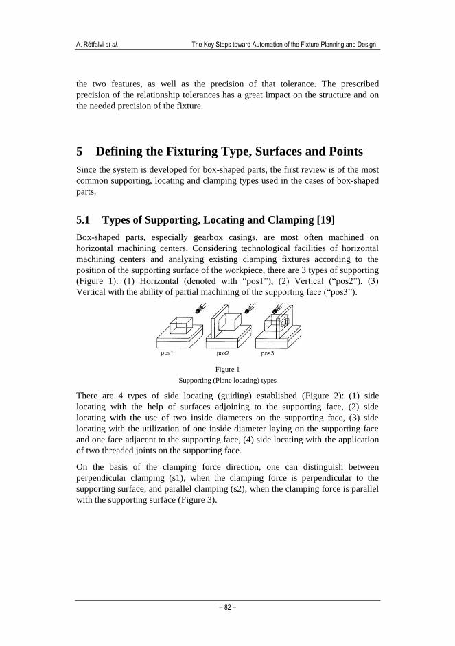
Box-shaped parts, especially gearbox casings, are most often machined on
horizontal machining centers. Considering technological facilities of horizontal
machining centers and analyzing existing clamping fixtures according to the
position of the supporting surface of the workpiece, there are 3 types of supporting
(Figure 1): (1) Horizontal (denoted with “pos1”), (2) Vertical (“pos2”), (3)
Vertical with the ability of partial machining of the supporting face (“pos3”).
Figure 1
Supporting (Plane locating) types
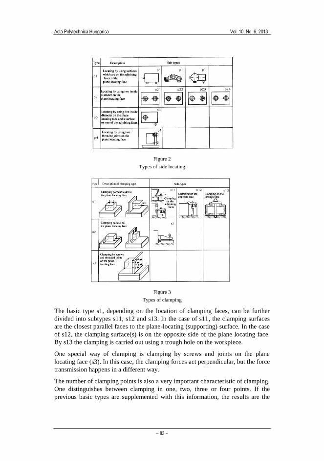
There are 4 types of side locating (guiding) established (Figure 2): (1) side
locating with the help of surfaces adjoining to the supporting face, (2) side
locating with the use of two inside diameters on the supporting face, (3) side
locating with the utilization of one inside diameter laying on the supporting face
and one face adjacent to the supporting face, (4) side locating with the application
of two threaded joints on the supporting face.
On the basis of the clamping force direction, one can distinguish between
perpendicular clamping (s1), when the clamping force is perpendicular to the
supporting surface, and parallel clamping (s2), when the clamping force is parallel
with the supporting surface (Figure 3).
Acta Polytechnica Hungarica Vol. 10, No. 6, 2013
– 83 –
Figure 2
Types of side locating
Figure 3
Types of clamping
The basic type s1, depending on the location of clamping faces, can be further
divided into subtypes s11, s12 and s13. In the case of s11, the clamping surfaces
are the closest parallel faces to the plane-locating (supporting) surface. In the case
of s12, the clamping surface(s) is on the opposite side of the plane locating face.
By s13 the clamping is carried out using a trough hole on the workpiece.
One special way of clamping is clamping by screws and joints on the plane
locating face (s3). In this case, the clamping forces act perpendicular, but the force
transmission happens in a different way.
The number of clamping points is also a very important characteristic of clamping.
One distinguishes between clamping in one, two, three or four points. If the
previous basic types are supplemented with this information, the results are the
A. Rétfalvi et al. The Key Steps toward Automation of the Fixture Planning and Design
– 84 –
possible clamping types: s11_2, s11_3, s11_4; s12_2, s12_3, s12_4; s13_1, s13_2;
s2_1, s2_2; s3_2, s3_3, s3_4. In the enumerated notation the last number denotes
the number of clamping points.
5.2 Suitable Surfaces for Locating and Clamping
5.2.1 Suitability for Plane Locating
The suitability of a surface for plane locating depends on the shape and size of the
surface. The best surfaces for plane locating are planar surfaces, then intermittent
planar surfaces, surfaces on different parallel planes, cylindrical surfaces, and
lastly a combination of cylindrical and planar surfaces.
The largest possible surface must be chosen for supporting the workpiece. The
minimal allowed size of supporting surfaces is given as a percent of the largest
dimensions of the part.
5.2.2 Suitability for Side Locating
a) Suitability for side locating type p1: Side locating can be divided into guiding
and end supporting.
Suitability for guiding must be tested based on 3 aspects: shape, size and position
of the surface.
According to the shape of the guide locating element, the useable faces
are: planar face, two planar faces, two cylindrical faces, a combination
of cylindrical and planar surfaces, and single cylindrical surface.
The typical dimension of a guiding surface must not be less than 35% of
the longest dimension of the plane locating face.
According to the position of the guiding element they must belong to
adjoining faces of the plane locating face.
Suitability for end supporting must be tested based on two aspects: the shape and
position of the surface.
According to the shape of the surface, planar or cylindrical surfaces can
be applied.
According to the position, they must be on a face that is adjacent to both
the locating and guiding faces.
b) Suitable surfaces for side locating type p2
According to the shape of the surface, there should be two holes on the plane
locating face. The distance between the holes must not be less than 35% of the
greatest length of the plane locating face.
Suitable surfaces for other side locating types are defined in a similar way.
Acta Polytechnica Hungarica Vol. 10, No. 6, 2013
– 85 –
5.2.3 Suitability for Clamping
The following principles must be respected during selection of clamping surfaces:
The awaking forces should push the workpiece to the fixture.
For the sake of rigid clamping, we must minimize the moments acting on
the workpiece.
The clamping should ensure positive rigidity.
The clamping force must not deform the workpiece.
The greatest shear force should be transmitted in a form-close way.
The clamping devices can be divided into two groups:
I. the clamping force changes with the deformation of the workpiece or the
clamping device (screws, cams, wedges, springs, etc); or
II. the clamping force is constant (hydraulic, pneumatic, magnetic, etc.)
Of course the constant clamping force is better, but it can be achieved only with
more expensive devices. So if the variation of clamping force is not too
significant, one prefers elements from the first group.
Exactly which device will be used depends on the shape, size and location of the
surfaces eligible for clamping.
For s1.1, the eligible surfaces are flat surfaces, through holes, or pockets; for s1.2
flat surfaces, intermittent planar faces or cylindrical surfaces; for s1.3 flat ring-like
surfaces, flat frame-like surfaces or group of cylindrical surfaces (with axes
perpendicular to the supporting face); for s2 flat surfaces, or intermittent planar
faces; and for s3 threaded holes.
The location of clamping surfaces is on the opposite side to the supporting face at
s1.1, s1.2 and s1.3; and at s1.3, the center of the hole is approximately coincident
with the center of the supporting surface. At s2 there are flat faces opposite to the
locating side, and they are near the supporting surface. At s3 there are threaded
holes on the supporting surface and the distance between them is great enough
(bigger than 40% of the height).
The size of the clamping face(s) should be large enough to ensure the settlement
of clamping devices and to ensure appropriate clamping pressure. At s3, M6 or
greater thread is needed.
In addition to these, one must check whether any of the above mentioned
principles are violated.
A. Rétfalvi et al. The Key Steps toward Automation of the Fixture Planning and Design
– 86 –
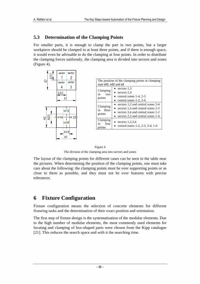
5.3 Determination of the Clamping Points
For smaller parts, it is enough to clamp the part in two points, but a larger
workpiece should be clamped in at least three points, and if there is enough space,
it would even be advisable to do the clamping at four points. In order to distribute
the clamping forces uniformly, the clamping area is divided into sectors and zones
(Figure 4).
The position of the clamping points at clamping type s11, s12 and s3
Clamping
in two
points
sectors 1,3
sectors 2,4
central zones 1-4, 2-3
central zones 1-2, 3-4
Clamping
in three points
sectors 1,2 and central zones 3-4
sectors 1,4 and central zones 2-3
sectors 3,4 and central zones 1-2
sectors 2,3 and central zones 1-4
Clamping
in four points
sectors 1,2,3,4
central zones 1-2, 2-3, 3-4, 1-4
Figure 4
The division of the clamping area into sectors and zones
The layout of the clamping points for different cases can be seen in the table near
the pictures. When determining the position of the clamping points, one must take
care about the following: the clamping points must be over supporting points or as
close to them as possible, and they must not be over features with precise
tolerances.
6 Fixture Configuration
Fixture configuration means the selection of concrete elements for different
fixturing tasks and the determination of their exact position and orientation.
The first step of fixture design is the systematization of the modular elements. Due
to the high number of modular elements, the most commonly used elements for
locating and clamping of box-shaped parts were chosen from the Kipp catalogue
[21]. This reduces the search space and with it the searching time.
Acta Polytechnica Hungarica Vol. 10, No. 6, 2013
– 87 –
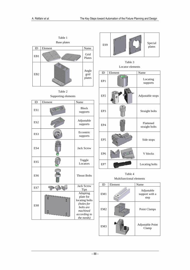
6.1 Systematization of the Modular Elements
The elements of a modular fixture can be divided into three groups:
a) base elements
b) functional elements
c) adapting elements
Base elements establish contact between the machine tool table and the fixture.
This group includes different palettes, grid plates, and angle grid plates. (Table 1)
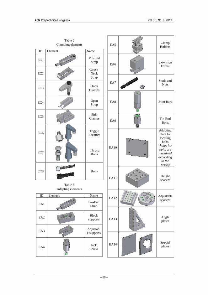
Functional elements are those elements that come in contact with the workpiece to
fulfill a concrete function such as supporting, locating or clamping. In this group
belong supports (Table 2), locators (Table 3), clamps (Table 5), and
multifunctional elements (Table 4).
These groups are subdivided according to similarity of function into further
subgroups, and a typical representative element of each subgroup is introduced in
the tables. Every subgroup receives an ID in order to facilitate the referencing.
These IDs are used in the next subsection (0), where the selection rules are
systematically presented.
In order to reduce the number of needed elements, fixture manufacturers combine
functions and thus offer multifunctional elements, too (Table 4). Of course, the
smaller the number of the elements in a fixture, the more stable and precise it is.
Adapting elements (Table 6) are not always used. Sometimes the clamping surface
is too high, or due to the shape of the workpiece, the supporting surface must be
elevated or the locating elements lengthened. In such cases, one uses adapting
elements to bridge the distance between the functional and the base elements.
The modular elements in the database are stored under coded names of the Kipp
catalogue, where the first four plus three numbers refer to the type and subtype of
the modular element. The following two numbers denote the size of the joining
surfaces, while the last three or four numbers refer to some of the more relevant
parameters of the element such as width, length or height. For example, in the
code 8000 081 123240, the 8000 signifies that it is a grid plate with holes on every
50 mm. 081 indicates there are holes for socket head screws to facilitate fixing of
the plate onto angle plate elements. 12 means the grid holes are M12 holes. 32 and
40 mean the width of the plate is 320 mm and length is 400 mm.
A. Rétfalvi et al. The Key Steps toward Automation of the Fixture Planning and Design
– 88 –
Table 1
Base plates
ID Element Name
EB1
Grid Plates
EB2
Angle
grid
plates
Table 2
Supporting elements
ID Element Name
ES1
Block
supports
ES2
Adjustable
supports
ES3
Eccentric
supports
ES4
Jack Screw
ES5
Toggle
Locators
ES6
Thrust Bolts
ES7
Jack Screw
Tips
ES8
Adapting
plate for
locating bolts (holes for
bolts are
machined
according to
the needs)
ES9
Special
plates
Table 3
Locator elements
ID Element Name
EP1
Locating
supports
EP2
Adjustable stops
EP3
Straight bolts
EP4
Flattened
straight bolts
EP5
Side stops
EP6
V blocks
EP7
Locating bolts
Table 4
Multifunctional elements
ID Element Name
EM1
Adjustable
support with a step
EM2
Point Clamps
EM3
Adjustable Point Clamp
Acta Polytechnica Hungarica Vol. 10, No. 6, 2013
– 89 –
Table 5
Clamping elements
ID Element Name
EC1
Pin-End Strap
EC2
Goose-
Neck
Strap
EC3
Hook
Clamps
EC4
Open
Strap
EC5
Side Clamps
EC6
Toggle Locators
EC7
Thrust
Bolts
EC8
Bolts
Table 6
Adapting elements
ID Element Name
EA1
Pin-End Strap
EA2
Block
supports
EA3
Adjustabl
e supports
EA4
Jack
Screw
EA5
Clamp
Holders
EA6
Extension
Forms
EA7
Studs and
Nuts
EA8
Joint Bars
EA9
Tie-Rod
Bolts
EA10
Adapting
plate for
locating bolts
(holes for
bolts are machined
according
to the needs)
EA11
Height
spacers
EA12
Adjustable
spacers
EA13
Angle plates
EA14
Special
plates
A. Rétfalvi et al. The Key Steps toward Automation of the Fixture Planning and Design
– 90 –
6.2 Systematic Presentation of the Selection Rules of Modular
Elements
First the base element is selected in accordance with the size of the machine table
and the type of the supporting (plane locating). Next the locators (and if needed,
the adapting elements) are selected. Finally, the clamping (and if needed,
adapting) elements are selected.
The selection rules are systematically ordered in matrices, and the columns
contain the tasks. In the rows there are the elements and the conditions under
which the elements can be used. 0 in the matrices means the element in question
cannot be used for the task in question; 1 means that it can always be used; other
symbols indicate under what circumstances it can be used. The nomenclature used
is:
¯| - NOT, V – OR, Λ – AND, PL - planar surface,
CYL - cylindrical surface, GPC - group of one planar and one cylindrical surface.
6.2.1 Selection of Base Elements
The selection of base elements depends on the dimensions of the machine tool’s
table, the dimensions of the workpiece, the type of supporting, the type of
clamping and the type of locating. If the machine tool is defined, the base
element’s selection matrix looks as follows:
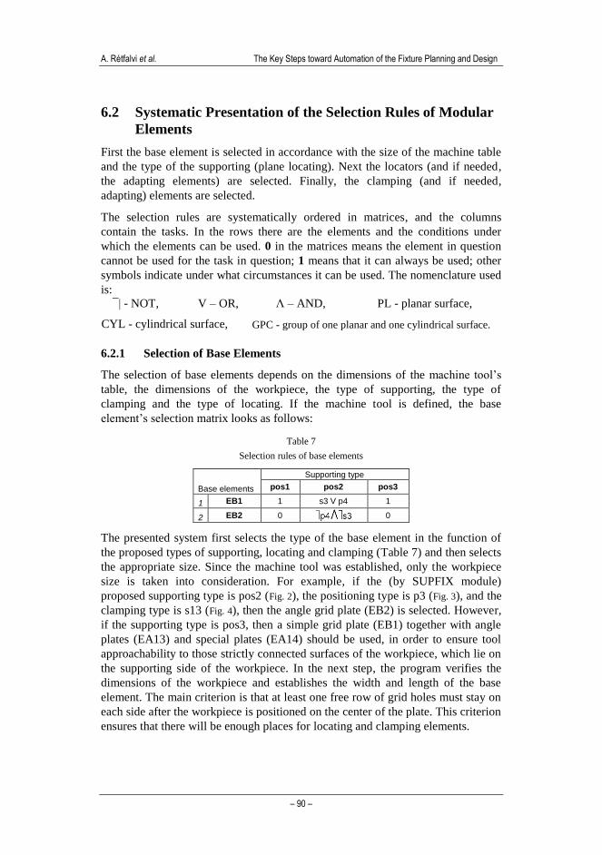
Table 7
Selection rules of base elements
Base elements
Supporting type
pos1 pos2 pos3
1 EB1 1 s3 V p4 1
2 EB2 0 0
The presented system first selects the type of the base element in the function of
the proposed types of supporting, locating and clamping (Table 7) and then selects
the appropriate size. Since the machine tool was established, only the workpiece
size is taken into consideration. For example, if the (by SUPFIX module)
proposed supporting type is pos2 (Fig. 2), the positioning type is p3 (Fig. 3), and the
clamping type is s13 (Fig. 4), then the angle grid plate (EB2) is selected. However,
if the supporting type is pos3, then a simple grid plate (EB1) together with angle
plates (EA13) and special plates (EA14) should be used, in order to ensure tool
approachability to those strictly connected surfaces of the workpiece, which lie on
the supporting side of the workpiece. In the next step, the program verifies the
dimensions of the workpiece and establishes the width and length of the base
element. The main criterion is that at least one free row of grid holes must stay on
each side after the workpiece is positioned on the center of the plate. This criterion
ensures that there will be enough places for locating and clamping elements.
Acta Polytechnica Hungarica Vol. 10, No. 6, 2013
– 91 –
Grid plates and MC plates (EB1) can always be used for supporting type pos1 and
pos3. For pos2, only when the clamping method is s3 or if the positioning type is
p4. Angled grid plates (EB2) are used only for supporting type pos2, since they
ensure greater rigidity, but can be used only when the positioning method is not p4
and clamping method is not s3.
The main elements of the code for selection of the base element are as follows:
base_element(ST,LT,CT,BE,) procedure (i,i,i,o).
selectSize(BET,SUT,W,L) procedure (i,o,o,o).
size1(wpD1,wpD2,SUT,W,L) procedure (i,i,o,o,o).
(ST – supporting type, LT - locating type, CT - clamping type, BE –base element, BET – base
element type, SUT – sub type, W - width, L – length, wpD1 – the width of the workpiece measured
parallel to supporting surface, wpD2 – the length of the workpiece measured parallel to the supporting surface)
base_element(“pos_2”,LT,CT,BE2):- not(LT=”p4”), not(CT=”s3”), !,
selectSize(“EB2”,A,B,C), concat(“8000”,A,”12”,B,C,”.igs”,BE2).
base_element(_,_,_,BE1):- selectSize(“EB1”,A,B,C),
concat(“8000”,A,”12”,B,C,”.igs”,BE1).
selectSize(“EB1”,A,B,C):- nx>ny, nx>nz, !, size1(yM,zM,A,B,C).
selectSize(“EB1”,A,B,C):- ny>nx, ny>nz, !, size1(xM,yM,A,B,C).
selectSize(“EB1”,A,B,C):- !, size1(xM,yM,A,B,C).
selectSize(_,A,B,C):- nx>ny, nx>nz, !, size2(yM,zM,A,B,C).
selectSize(_,A,B,C):- ny>nx, ny>nz, !, size2(xM,zM,A,B,C).
selectSize(_,A,B,C):- size2(xM,yM,A,B,C).
The program first checks if the proposed supporting type is pos_2: if yes, then it
verifies if the locating type is p4, and if not it verifies if the clamping type is s3; if
not, then it selects the angled grid plate (EB2). In any other case, the grid plate
(EB1) is selected. The concrete base element is selected in the function of the
workpiece dimensions that are parallel with the supporting surface. For example,
if the supporting surface’s normal vector points in x direction, then yMax and
zMmax dimensions are considered. These data are obtained from the workpiece
model during feature recognition (IPPO module) and are stored in appropriate
variables.
6.2.2 Selection of Locating Elements
The locating task can be divided into two sub tasks, guiding and end stopping.
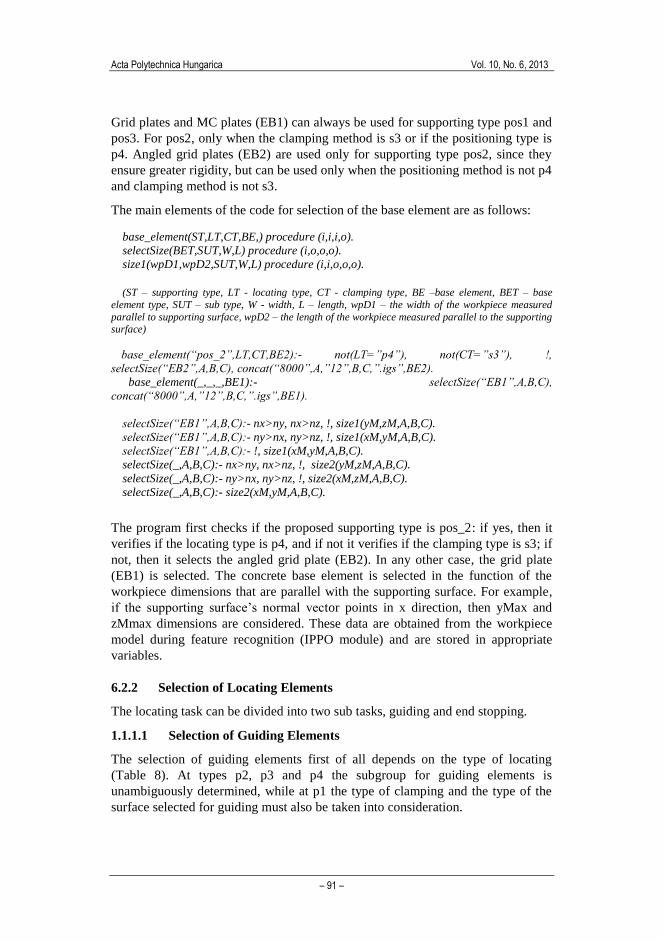
1.1.1.1 Selection of Guiding Elements
The selection of guiding elements first of all depends on the type of locating
(Table 8). At types p2, p3 and p4 the subgroup for guiding elements is
unambiguously determined, while at p1 the type of clamping and the type of the
surface selected for guiding must also be taken into consideration.
A. Rétfalvi et al. The Key Steps toward Automation of the Fixture Planning and Design
– 92 –
For example, if one wants to solve p1 type locating, and the clamping type is not
s2 and there is an eligible plane surface for locating, then it is possible to use two
locating supports (EP1), or two adjustable stops (EP2), or one locating support and
one adjustable stop. But if the only possible clamping method is s2, then some
kind of side stops (EP5) should be used.
Table 8
Selection of guiding locators
Locators
Type of locating
p1 p2 p3 p4
1 2 x EP1 0 0 0
2 2 x EP2 0 0 0
3 EP1 + EP2 0 0 0
4 EP3 0 1 1 0
5 EP5 s2 0 0 0
6 2 x EP5 s2 0 0 0
7 2 x EP6 CYL 0 0 0
8 EP6 + EP2 GC 0 0 0
9 EP7 0 0 0 1
Table 9
Selection of end stop locators
Locators
Type of locating
p1 p21 p22
p23 p24
p3 p4
1 EP1 PL 0 0 0 0
2 EP2 PL 0 0 1 0
3 EP3 0 1 0 0 0
4 EP4 0 0 1 0 0
5 EP5 CYL 0 0 0 0
6 EP6 0 0 0 0 1
1.1.1.2 Selection of End Stops
The selection of end stops depends on the type of locating and also on the type of
the selected end stop surface (Table 9).
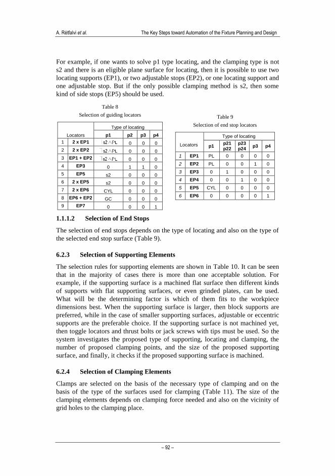
6.2.3 Selection of Supporting Elements
The selection rules for supporting elements are shown in Table 10. It can be seen
that in the majority of cases there is more than one acceptable solution. For
example, if the supporting surface is a machined flat surface then different kinds
of supports with flat supporting surfaces, or even grinded plates, can be used.
What will be the determining factor is which of them fits to the workpiece
dimensions best. When the supporting surface is larger, then block supports are
preferred, while in the case of smaller supporting surfaces, adjustable or eccentric
supports are the preferable choice. If the supporting surface is not machined yet,
then toggle locators and thrust bolts or jack screws with tips must be used. So the
system investigates the proposed type of supporting, locating and clamping, the
number of proposed clamping points, and the size of the proposed supporting
surface, and finally, it checks if the proposed supporting surface is machined.
6.2.4 Selection of Clamping Elements
Clamps are selected on the basis of the necessary type of clamping and on the
basis of the type of the surfaces used for clamping (Table 11). The size of the
clamping elements depends on clamping force needed and also on the vicinity of
grid holes to the clamping place.
Acta Polytechnica Hungarica Vol. 10, No. 6, 2013
– 93 –
Table 10
Selection rules of supports
Supports
Supporting surfaces
Machined plane
surface
Group of machined plane surfaces at same
height
Group of machined plane surfaces at two different heights
Raw plane surface, Group of
raw surfaces
Group of raw plane surfaces at two different
heights
1 2 x ES1 (p1 V p3)
+ (s2 V s4)
(p1 V p3) +
(s2 V s4) 0 0 0
2 4 x ES1 (p1 V p3)
+ s4 (p1 V p3)
+ s4 0 0 0
3 2 x ES2 (p1 V p3)
+ (s2 V s4)
(p1 V p3) +
(s2 V s4) 0 0 0
4 4 x ES2 (p1 V p3) + s4 (p1 V p3) + s4 0 0 0
5 3 x ES3 (p1 V p3) + s3 (p1 V p3) + s3 0 0 0
6 4 x ES3 (p1 V p3) + s4 (p1 V p3) + s4 0 0 0
7 ES1+ES4 0 0 (p1 V p3) + s2 0 0
8 ES2+ES4 0 0 (p1 V p3) + s2 0 0
9 2 x ES3 +ES4 0 0 (p1 V p3) + s3 0 0
10 ES8 p2 V p3 p2 V p3 0 0 0
11 2 x ES8 0 0 p2 0 0
12 ES9 p4 V pos3 p4 V pos3 0 0 0
13 3 x ES5 0 0 0 p1 V p3 0
14 3 x ES6 0 0 0 p1 V p3 0
15 2 x ES5 +ES6 0 0 0 0 p1 V p3
16 2 x ES5 +ES7 0 0 0 0 p1 V p3
* here the numbers beside the letter s denote the number of clamping points
The number of clamps is equal to the number of necessary clamping points that
are prescribed (by SUPFIX) in the conceptual solution of the fixture. It may
happen that in different points different types of clamps are needed. Toggle
locators (EC6) and thrust bolts (EC7) are used to increase the clamping range of
hook clamps (EC3) at s12 type clamping. The usage of hook clamps is restricted
by the grid hole positions: that is, they can be used if there is a grid hole (G
HOLE) close enough to the proposed clamping point. If one wants to clamp the
workpiece on an inner cylindrical surface, a pin-end strap (EC1) is to be used.
6.2.5 Selection of Adapting Elements
Adapting elements are configured so that they can be connected not only to the
base and functional elements, but also to each other. Table 12 shows how the
adapting elements can be combined with each other. Table 13 shows which
functional element and adapting element can be combined. Theoretically the
number of adapting elements used in a chain that connects a base and a functional
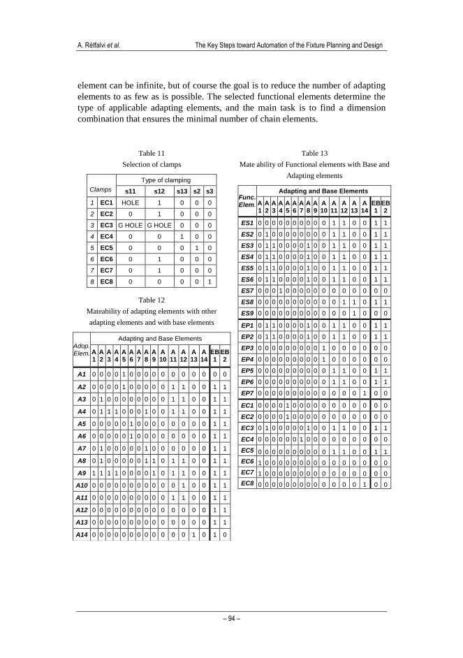
A. Rétfalvi et al. The Key Steps toward Automation of the Fixture Planning and Design
– 94 –
element can be infinite, but of course the goal is to reduce the number of adapting
elements to as few as is possible. The selected functional elements determine the
type of applicable adapting elements, and the main task is to find a dimension
combination that ensures the minimal number of chain elements.
Table 11
Selection of clamps
Clamps
Type of clamping
s11 s12 s13 s2 s3
1 EC1 HOLE 1 0 0 0
2 EC2 0 1 0 0 0
3 EC3 G HOLE G HOLE 0 0 0
4 EC4 0 0 1 0 0
5 EC5 0 0 0 1 0
6 EC6 0 1 0 0 0
7 EC7 0 1 0 0 0
8 EC8 0 0 0 0 1
Table 12
Mateability of adapting elements with other
adapting elements and with base elements
Adop. Elem.
Adapting and Base Elements
A 1
A 2
A 3
A 4
A 5
A 6
A 7
A 8
A 9
A 10
A 11
A 12
A 13
A 14
EB 1
EB 2
A1 0 0 0 0 1 0 0 0 0 0 0 0 0 0 0 0
A2 0 0 0 0 1 0 0 0 0 0 1 1 0 0 1 1
A3 0 1 0 0 0 0 0 0 0 0 1 1 0 0 1 1
A4 0 1 1 1 0 0 0 1 0 0 1 1 0 0 1 1
A5 0 0 0 0 0 1 0 0 0 0 0 0 0 0 1 1
A6 0 0 0 0 0 1 0 0 0 0 0 0 0 0 1 1
A7 0 1 0 0 0 0 0 1 0 0 0 0 0 0 1 1
A8 0 1 0 0 0 0 0 1 1 0 1 1 0 0 1 1
A9 1 1 1 1 0 0 0 0 1 0 1 1 0 0 1 1
A10 0 0 0 0 0 0 0 0 0 0 0 1 0 0 1 1
A11 0 0 0 0 0 0 0 0 0 0 1 1 0 0 1 1
A12 0 0 0 0 0 0 0 0 0 0 0 0 0 0 1 1
A13 0 0 0 0 0 0 0 0 0 0 0 0 0 0 1 1
A14 0 0 0 0 0 0 0 0 0 0 0 0 1 0 1 0
Table 13
Mate ability of Functional elements with Base and
Adapting elements
Func. Elem.
Adapting and Base Elements
A 1
A 2
A 3
A 4
A 5
A 6
A 7
A 8
A 9
A 10
A 11
A 12
A 13
A 14
EB 1
EB 2
ES1 0 0 0 0 0 0 0 0 0 0 1 1 0 0 1 1
ES2 0 1 0 0 0 0 0 0 0 0 1 1 0 0 1 1
ES3 0 1 1 0 0 0 0 1 0 0 1 1 0 0 1 1
ES4 0 1 1 0 0 0 0 1 0 0 1 1 0 0 1 1
ES5 0 1 1 0 0 0 0 1 0 0 1 1 0 0 1 1
ES6 0 1 1 0 0 0 0 1 0 0 1 1 0 0 1 1
ES7 0 0 0 1 0 0 0 0 0 0 0 0 0 0 0 0
ES8 0 0 0 0 0 0 0 0 0 0 0 1 1 0 1 1
ES9 0 0 0 0 0 0 0 0 0 0 0 0 1 0 0 0
EP1 0 1 1 0 0 0 0 1 0 0 1 1 0 0 1 1
EP2 0 1 1 0 0 0 0 1 0 0 1 1 0 0 1 1
EP3 0 0 0 0 0 0 0 0 0 1 0 0 0 0 0 0
EP4 0 0 0 0 0 0 0 0 0 1 0 0 0 0 0 0
EP5 0 0 0 0 0 0 0 0 0 0 1 1 0 0 1 1
EP6 0 0 0 0 0 0 0 0 0 0 1 1 0 0 1 1
EP7 0 0 0 0 0 0 0 0 0 0 0 0 0 1 0 0
EC1 0 0 0 0 1 0 0 0 0 0 0 0 0 0 0 0
EC2 0 0 0 0 1 0 0 0 0 0 0 0 0 0 0 0
EC3 0 1 0 0 0 0 0 1 0 0 1 1 0 0 1 1
EC4 0 0 0 0 0 0 1 0 0 0 0 0 0 0 0 0
EC5 0 0 0 0 0 0 0 0 0 0 1 1 0 0 1 1
EC6 1 0 0 0 0 0 0 0 0 0 0 0 0 0 0 0
EC7 1 0 0 0 0 0 0 0 0 0 0 0 0 0 0 0
EC8 0 0 0 0 0 0 0 0 0 0 0 0 0 1 0 0
Acta Polytechnica Hungarica Vol. 10, No. 6, 2013
– 95 –
When a functional element is selected, the system instantly checks if there is a
need for an adapting element. From the characteristic dimension (usually the
height) of the surface with which the functional element is in contact is subtracted
the position of the surface of the ground element, in the direction of the surfaces
normal. The difference is reduced with the distance between the contact surfaces
toward the workpiece and toward the adapter element. This should be bridged
with an adapting element or elements. Naturally, the range of the adjustability of
the functional element is taken into consideration.
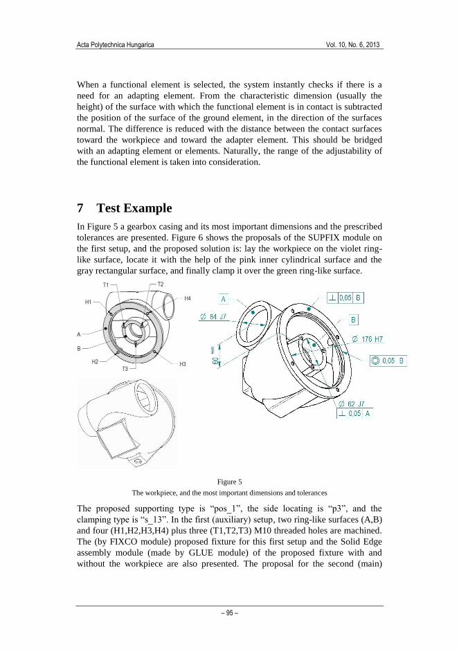
7 Test Example
In Figure 5 a gearbox casing and its most important dimensions and the prescribed
tolerances are presented. Figure 6 shows the proposals of the SUPFIX module on
the first setup, and the proposed solution is: lay the workpiece on the violet ring-
like surface, locate it with the help of the pink inner cylindrical surface and the
gray rectangular surface, and finally clamp it over the green ring-like surface.
Figure 5
The workpiece, and the most important dimensions and tolerances
The proposed supporting type is “pos_1”, the side locating is “p3”, and the
clamping type is “s_13”. In the first (auxiliary) setup, two ring-like surfaces (A,B)
and four (H1,H2,H3,H4) plus three (T1,T2,T3) M10 threaded holes are machined.
The (by FIXCO module) proposed fixture for this first setup and the Solid Edge
assembly module (made by GLUE module) of the proposed fixture with and
without the workpiece are also presented. The proposal for the second (main)
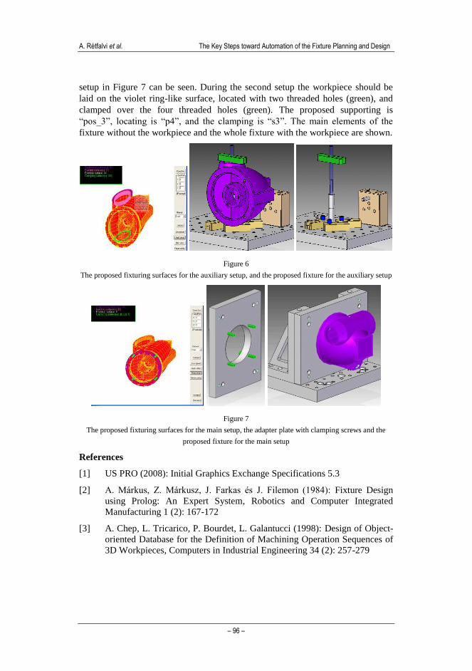
A. Rétfalvi et al. The Key Steps toward Automation of the Fixture Planning and Design
– 96 –
setup in Figure 7 can be seen. During the second setup the workpiece should be
laid on the violet ring-like surface, located with two threaded holes (green), and
clamped over the four threaded holes (green). The proposed supporting is
“pos_3”, locating is “p4”, and the clamping is “s3”. The main elements of the
fixture without the workpiece and the whole fixture with the workpiece are shown.
Figure 6
The proposed fixturing surfaces for the auxiliary setup, and the proposed fixture for the auxiliary setup
Figure 7
The proposed fixturing surfaces for the main setup, the adapter plate with clamping screws and the
proposed fixture for the main setup
References
[1] US PRO (2008): Initial Graphics Exchange Specifications 5.3
[2] A. Márkus, Z. Márkusz, J. Farkas és J. Filemon (1984): Fixture Design
using Prolog: An Expert System, Robotics and Computer Integrated
Manufacturing 1 (2): 167-172
[3] A. Chep, L. Tricarico, P. Bourdet, L. Galantucci (1998): Design of Object-
oriented Database for the Definition of Machining Operation Sequences of
3D Workpieces, Computers in Industrial Engineering 34 (2): 257-279
Acta Polytechnica Hungarica Vol. 10, No. 6, 2013
– 97 –
[4] B. S. Prabhu, S. Biswas, S. S. Pande (2001): Intelligent System for
Extraction of Product Data from CADD Models, Computers in Industry
44:79-95
[5] A. Arivazhagan, N. K. Mehta, P. K. Jain (2009): A STEP AP 203 – 214-
based Machinable Volume Identifier for Identifying the Finish-Cut
Machinable Volumes from Rough Machined Parts, Int. J. Adv. Manuf.
Technol. 42:850-872, doi 10.1007/s00170-008-1659-2
[6] S. R. Subrahmanyam (2002): A Method for Generation of Machining and
Fixturing Features from Design Features, Computers in Industry 47: 269-
287
[7] J. Kakish, P. L. Zhang, I. Zheid (2000): Towards the Design and
Development of a Knowledge-based Universal Modular Jigs and Fixture
Systems, J. of Intelligent Manufacturing 11:381-401
[8] X. Zhou, Y. Qiu, G. Hua, H. Wang, X. Ruan (2007): A Feasible Approach
to the Integration of CAD and CAPP, Computer Aided Design 39:324-338
[9] V. Rameshbabu, M. S. Shunmugam (2009): Hybrid Feature Recognition
Method for Setup Planning from STEP AP 203, Robotics and Compurter
Integrated Manufacturing 25: 393-408
[10] Y. Wu, S. Gao, Z. Chen (2008): Automated Modular Fixture Planning
Based on Linkage Mechanism Theory, Robotics and Computer Integrated
Manufacturing 24: 38-49
[11] I. Boyle, Y. Rong, D. C. Brown (2011): A Review and Analysis of Current
Computer-Aide Fixture Design Approaches, Robotics and Computer
Integrated Manufacturing 27:1-12
[12] X. Xu, L. Wang, S. T. Newman (2011): Computer-aided Process Planning -
A Critical Review of Recent Developments and Future
Trends, International Journal of Computer Integrated Manufacturing 24 (1):
1-31
[13] R. H. Alacron, J. R. Chueco, J. M. P. Garcia, A. V. Idiope (2010): Fixture
Knowledge Model Development and Implementation Based on a
Functional Design Approach, Robotics and Computer Integrated
Manufacturing 26:56-66
[14] H. Paris, D. Brissaud (2005): Process Planning Strategy Based on Fixturing
Indicator Evaluation, Int J Adv Manuf Technol 25: 913-922
[15] A. S. Kumar, J. Y. H. Fuh, T. S. Kow (2000): An Automated Design and
Assembly of Interference Free Modular Fixture Setup, Computer-aided
Design 32:583-596
[16] P. Perremans (1996): Feature-based Description of Modular Fixturing
Elements: the Key to an Expert System for the Automatic Design of the
Physical Fixture, Advances in Engineering Software 25: 19-27
A. Rétfalvi et al. The Key Steps toward Automation of the Fixture Planning and Design
– 98 –
[17] Đ. Vukelić, U. Zuperl, J. Hodolic (2009): Complex System for Fixture
Selection, Modification and Design, Int J Adv Manuf Technol 45:731-748
[18] S. Bansal, S. Nagarajan, N. V. Reddy (2008): An Integrated Fixture
Planning System for Minimum Tolerances, Int J Adv Manuf Technol
38:501-513
[19] M. Stampfer (2009): Automated Setup and Fixture Planning System for
Box-shaped Parts, Int J Adv Manuf Technol 45:540-552
[20] Rétfalvi A. (2011): IGES-based CAD Model Post Processing Module of a
Setup and Fixture Planning System for Box-shaped Parts, IEEE 9th
International Symposium on Intelligent Systems and Informatics,
September 8-10, 2011, Subotica, Serbia
[21] Heinrich Kipp Werk: Workholding Systems, Catalogue of the Modular
Fixture Elements