Embed Size (px)
Citation preview
Insulation
Low Energy –Low Carbon Buildings
GLOBAL SPECIFICATION MANUAL
The Kingspan System
CI/SfB(57.9) In7 (M2)
Seventh Issue March 2012
Manufactured to BS EN ISO 9001: 2000Certificate No. 388

2
Contents
Page
Introduction 3
Prestige Projects 4
System Benefits 14
Product Data 22
Issues to ConsiderWhole Life costs 24Economy of Duct Design 25Weight 26Installation Speed 28Energy & Running Costs 30Moisture & Exacerbated Heat Loss / Gain 32Sustainability 34Embodied Energy 36
Project Specification 38UK & Ireland (Appendix A) 41Australia (Appendix B) 46Middle East (Appendix C) 52North America (Appendix D) 58

3
OverviewThe Heating, Ventilation, and Air Conditioning (HVAC) industryis in the midst of a dynamic era. However, air distributionductwork, a critical component of HVAC systems, has remainedvirtually unchanged since the early 1900’s. Several factors andrecent innovations have introduced the need to revolutionise airdistribution ductwork. Building materials and insulating productshave dramatically improved. Requirements for clean air arebecoming increasingly stringent. Energy use has continued toescalate. Speed of construction has become a valuable asset.Floor space and headroom are under constant pressure.
The Kingspan KoolDuct® System is like no other insulatedductwork system. It is the most advanced and innovativeSystem of pre–insulated air distribution ductwork availableworldwide. The Kingspan KoolDuct® System of pre–insulatedductwork is a proven, innovative product that is easy toinstall and maintain, providing a new perspective in the fieldof air distribution.
Kingspan KoolDuct® rigid phenolic insulation panels have beenproduced since the early 1990’s and have been used in themanufacture of ductwork from the Kingspan KoolDuct® Systemworldwide. The components and techniques that are associatedwith the fabrication of ductwork from the Kingspan KoolDuct®
System have been established in the European marketplacesince the mid 1960’s.
This fourth generation Kingspan KoolDuct® System virtuallyeliminates all the problems of traditional metal ductwork whileat the same time offering extra advantages to both theconsulting / mechanical engineer and the fabricator / installer.The System is the clear leader in the new generation ofinsulated pre–fabricated ductwork and has already proved itselfin the highly competitive global marketplace.
What’s Different About theKingspan KoolDuct® System?Traditionally, air distribution ductwork is made of sheet metalwhich is installed first and then insulated separately as asecond operation. Kingspan KoolDuct® System pre–insulatedductwork is installed in a single fix.
The Kingspan KoolDuct® System comprises either 3 m / 10 ftor 4 m / 13 ft long ductwork sections fabricated from rigidphenolic insulation panels with aluminium surfaces.
Introduction
4
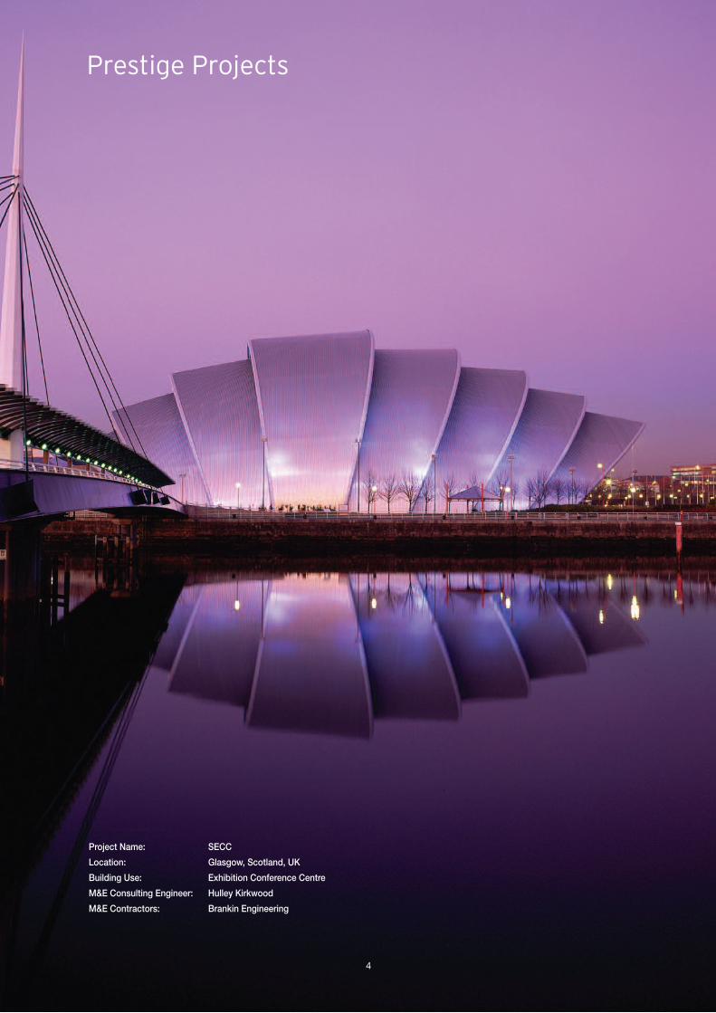
Prestige Projects
Project Name: SECC
Location: Glasgow, Scotland, UK
Building Use: Exhibition Conference Centre
M&E Consulting Engineer: Hulley Kirkwood
M&E Contractors: Brankin Engineering

5
Project Name: Shangri–La Hotel
Location: Dubai, UAE
Volume: 10,000 m2
Building Use: Hotel
M&E Consulting Engineer: NORR Group Consultants International
M&E Contractor: Sensaire Services
Main Contractor: Al Habtoor Engineering / Murray & Roberts
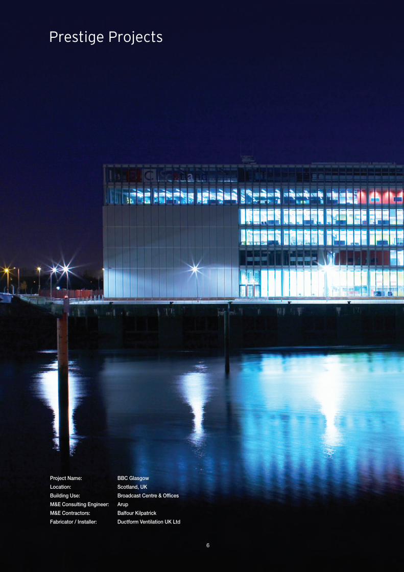
Prestige Projects
Project Name: BBC Glasgow
Location: Scotland, UK
Building Use: Broadcast Centre & Offices
M&E Consulting Engineer: Arup
M&E Contractors: Balfour Kilpatrick
Fabricator / Installer: Ductform Ventilation UK Ltd
6

7

Prestige Projects
Project Name: Lincoln University
Location: Lincoln, UK
Building Use: University
M & E Consulting Engineer: HBG
Installer / Fabricator: Ducted Air Systems Ltd.
8

9
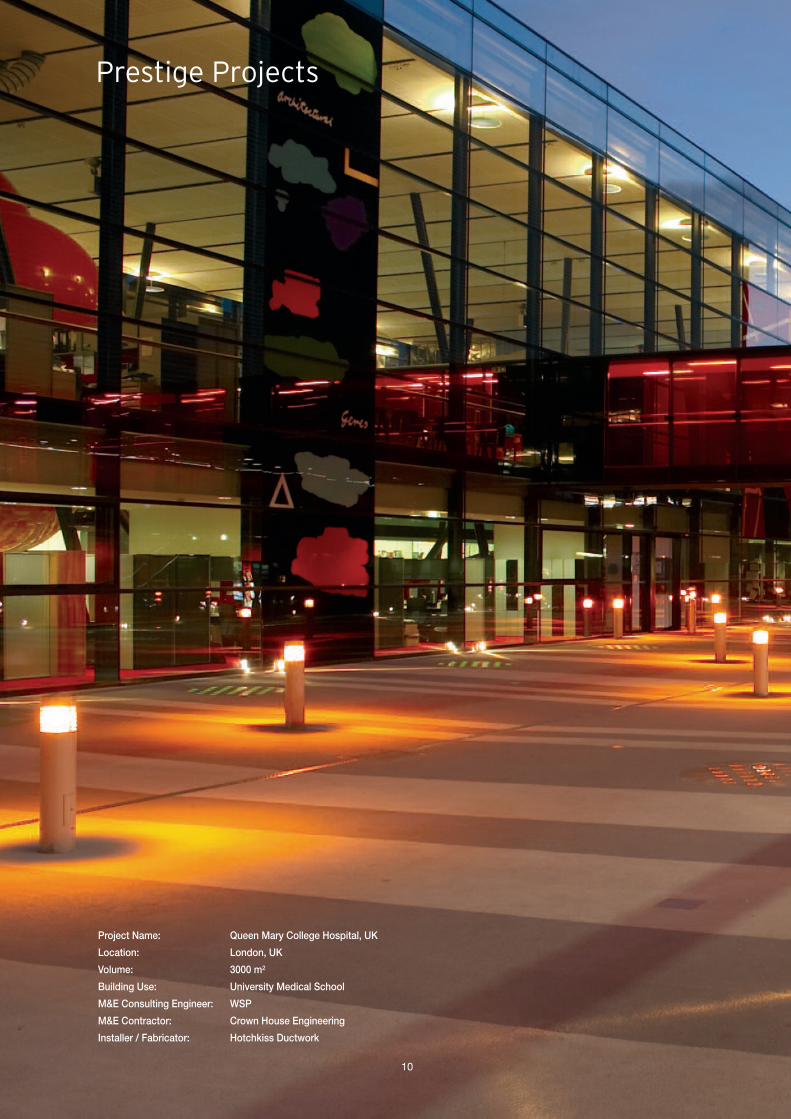
Prestige Projects
Project Name: Queen Mary College Hospital, UK
Location: London, UK
Volume: 3000 m2
Building Use: University Medical School
M&E Consulting Engineer: WSP
M&E Contractor: Crown House Engineering
Installer / Fabricator: Hotchkiss Ductwork
10

11

Prestige Projects
Project Name: Atlantis, The Palm, Dubai
Location: Dubai, UAE
Volume: 13,650 m2
Building Use: Hotel Resort
M&E Consulting Engineer: NORR Group Consultants International
M&E Contractor: BK Gulf LLC / Rotary HUMM Services LLC
Fabricator: Seagull HVAC Industry LLC
12

Project Name: Darwin Centre, Natural History Museum
Location: London, UK
Volume: 1200 m2
Building Use: Museum / Research & Collections Facility
M&E Consulting Engineer: Fulcrum Consulting
M&E Contractor: Imtech Meica Ltd
Fabricator / Installer: RDS
13
Tigerconnector
Dynamic branch
Volume controldampers
Elbow
Dynamic tee
Aluminiumgrip flange
Galvanisedsteel support
14
Whole Life Costs‘Whole life’ costing takes account of the total cost of an itemover its life, including durability, energy savings and maintenanceas well as initial purchase price.
Independent consultants, Cyril Sweett, carried out an analysis ofthe ‘whole life’ costs of differing HVAC ductwork specifications.The research showed that the installation of the KingspanKoolDuct® System can save up to 21% on capital cost.Furthermore, over a 30 year life, the Kingspan KoolDuct®
System can also make a saving of over 20% on operating costs.
For further information on the benefits of the System’s‘whole life’ costs, please refer to the Issues to Considersection of this document.
Installed CostResearch, by independent consultants Rider Levett Bucknall,continues to show that the installed cost of the KingspanKoolDuct® System is cheaper than that of insulated sheetmetal ductwork; up to 19% cheaper for larger ducts. Thisresearch, carried out in the UK, compared ductwork sectionsfabricated from 22 mm / 7/8” and 33 mm / 15/16” KingspanKoolDuct® rigid phenolic insulation panels and the 4–boltflange jointing system, with 40 mm / 19/16” and 55 mm / 23/16”mineral fibre insulated galvanised sheet steel ductwork.
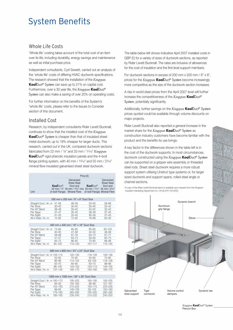
The table below left shows indicative April 2007 installed costs inGBP (£) for a variety of sizes of ductwork sections, as reportedby Rider Levett Bucknall. The rates are inclusive of allowancesfor the cost of insulation and the first level support members.
For ductwork sections in excess of 200 mm x 200 mm / 8” x 8”,prices for the Kingspan KoolDuct® System become increasinglymore competitive as the size of the ductwork section increases.
A rise in world steel prices from the April 2007 level will furtherincrease the competitiveness of the Kingspan KoolDuct®
System, potentially significantly.
Additionally, further savings on the Kingspan KoolDuct® Systemprices quoted could be available through volume discounts onmajor projects.
Rider Levett Bucknall also reported a general increase in themarket share for the Kingspan KoolDuct® System asconstruction industry customers have become familiar with theproduct and the benefits its use brings.
A key factor in the differences shown in the table left is inthe cost of the ductwork supports. In most circumstances,ductwork constructed using the Kingspan KoolDuct® Systemcan be supported on a gripper wire assembly or threadedsteel rods. Sheet steel ductwork requires a more robustsupport system utilising Unistrut type systems or, for largersized ductwork and support spans, rolled steel angle orchannel sections.
*A copy of the Rider Levett Bucknall report is available upon request from the KingspanInsulation Marketing Department on +44 (0) 870 733 8333.
System Benefits
Price (£)
Galvanised GalvanisedSheet Steel Sheet Steel
KoolDuct® Duct and KoolDuct® Duct and22 mm / 7/8” 40 mm / 19/16” mm 33 mm / 15/16” 55 mm / 23/16”
Unit (4–bolt Flange) Mineral Fibre (4–bolt Flange) Mineral Fibre
200 mm x 200 mm / 8” x 8” Duct Size
Straight Duct / lin. m 47–56 48–58 50–60 58–68Per Shoe 30–40 30–40 30–40 32–42Per 45º Bend 38–48 30–40 42–52 32–42Per Taper 37–47 35–45 38–48 37–45Per Sq90 41–50 35–45 46–56 37–45All in Rate / lin. m 72–82 72–82 78–88 82–92
400 mm x 400 mm / 16” x 16” Duct Size
Straight Duct / lin. m 75–85 85–95 85–95 90–100Per Shoe 40–50 47–58 42–52 48–58Per 45º Bend 58–68 67–76 63–73 67–77Per Taper 47–57 63–73 50–60 65–75Per Sq90 65–75 86–95 70–80 88–98All in Rate / lin. m 95–105 110–120 107–117 115–125
600 mm x 600 mm / 24” x 24” Duct Size
Straight Duct / lin. m 105–115 120–130 118–128 126–136Per Shoe 52–62 75–85 55–65 75–85Per 45º Bend 86–96 115–125 93–103 118–128Per Taper 62–70 85–95 63–73 88–98Per Sq90 96–105 143–153 103–113 145–155All in Rate / lin. m 137–145 160–170 150–160 165–175
1000 mm x 1000 mm / 39” x 39” Duct Size
Straight Duct / lin. m 160–170 195–205 185–195 195–205Per Shoe 84–93 155–165 88–98 157–167Per 45º Bend 152–160 215–225 165–175 220–228Per Taper 88–95 145–155 92–102 150–160Per Sq90 176–185 283–293 195–205 285–295All in Rate / lin. m 185–195 230–240 210–220 240–250
Kingspan KoolDuct® SystemPlenum Box

Pre-insulated Circular Duct
4–bolt flangeTiger support
Access panel
Fire damper unit positionedin dividing wall
15
WeightThe exceptional strength to weight ratio of the KingspanKoolDuct® System of pre–insulated ductwork results inductwork that is lightweight, easy to handle and install.It can be seen from the table to the right that ductwork sectionsfabricated from Kingspan KoolDuct® rigid phenolic insulationpanels can weigh up to 85% less than insulated galvanisedsheet steel ductwork. This results in easier installation and muchlower handling costs because fewer people are required toinstall a ductwork section. Two individuals can quickly and easilyinstall substantially sized ductwork sections fabricated from theKingspan KoolDuct® System of pre–insulated ductwork.
Many older buildings involved in refurbishment projects may notbe designed to support the additional weight of insulated sheetsteel ductwork. The Kingspan KoolDuct® System can generallyalleviate the requirement for additional structural support.
Research, by independent consultants Rider Levett Bucknall,into a selection of UK refurbishment projects using thealuminium grip flange jointing system and 22 mm / 7/8” panelthickness, has shown that the main reason for specifying theKingspan KoolDuct® System is that it can overcome severeconstraints on structural loadings.
In these circumstances, the selection of the KingspanKoolDuct® System over a galvanised sheet steel ductworksystem was often the only realistic choice: the alternativenormally being the introduction, at potentially significantadditional cost, of secondary steel supports to transfer serviceloads back to the structure. In some projects, even this optionwas not available for example, where buildings containedfeatures of architectural or historic importance that could not beobscured by the introduction of new structural members.
For further information on the benefits of the System’slight weight, please refer to the Issues to Consider sectionof this document.
Galvanised Sheet SteelKingspan Insulated with
KoolDuct® Mineral FibreInsulation Ductwork Insulation Ductwork Weight
Specification Thickness Weight Thickness Weight Reduction (%)
TIMSA Warm Air 22 mm 5.5 kg 29 mm 37.7 kg 85.3TIMSA Chilled Air 30 mm 7.6 kg 50 mm 41.8 kg 81.8& Dual PurposeBS 5422: 2001 22 mm 5.5 kg 34 mm 38.6 kg 85.7Warm Air with10°C ∆TBS 5422: 2001 22 mm 5.5 kg 37 mm 39.2 kg 85.9Warm Air with15°C ∆TBS 5422: 2001 30 mm 7.6 kg 44 mm 40.6 kg 81.3Warm Air with25°C ∆TBS 5422: 2001 22 mm 5.5 kg 35 mm 36.9 kg 85.0Chilled Air at 15°CBS 5422: 2001 22 mm 5.5 kg 37 mm 39.2 kg 85.9Chilled Air at 12°CBS 5422: 2001 30 mm 7.6 kg 45 mm 40.8 kg 81.4Chilled Air at 10°CBCA 2008 Spec. 22 mm 5.5 kg 38 mm 35.7 kg 84.5J5.2–3 Table 3b 30 mm 7.6 kg 50 mm 36.9 kg 79.4
33 mm 8.4 kg 75 mm 39.4 kg 78.7ANSI / ASHRAE / 7/8” 12.1 lb 11/2” 75.2 lb 83.8IESNA 90.1: 2007 7/8” 12.1 lb 23/16” 77.4 lb 84.2
13/16” 16.8 lb 3” 79.8 lb 79.0
Assumptions used are identical to those used in creating the table for the Embodied Energychapter of the Issues to Consider section of this document.
Table Showing the Weight Reduction of Kingspan KoolDuct® overGalvanised Sheet Steel Insulated with Mineral Fibre for a 1 m / 3.3 ftLong Ductwork Section to Various Specifications

Air Leakage / Energy / Running CostsThe Kingspan KoolDuct® System technology, the fabricationmethodology combined with the jointing systems and thecomplete line of bespoke accessories produce a system wherethe air leakage can be reduced to a fraction of that typical ofsheet metal ductwork. For systems designed to withstand astatic pressure of up to and including 1000 Pa / 4 in.w.g., theKingspan KoolDuct® System can easily meet the air leakagerequirements as shown in the table below.
Jointing SystemAir Leakage Aluminium TigerStandard Grip 4–bolt Connector
BS EN 13403: 2003 Class C Class C Class CBS EN 1507: 2006 Class C Class C Class DHVCA DW/144 Class C Class C Class CSMACNA Class 3 Class 3 Class 3NB BS EN 13403: 2003 (Ventilation for buildings. Non metallic ducts. Ductwork made frominsulation ductboards) is not applicable to sheet metal ductwork.
16
Installation SpeedThe Kingspan KoolDuct® System has a single fix installation, byvirtue of eliminating the manual process of applying theinsulation around the ductwork as a separate operation, thusreducing site time and contractor management. The ability tofabricate up to 3 m / 10 ft or 4 m / 13 ft long sections ratherthan 1.2 m / 4 ft or 1.5 m / 5 ft long sections as in the case ofsheet steel ductwork, means fewer sections and less handling.This coupled with increased support centres and ease ofhandling results in a fast track installation.
Research, by independent consultants Rider Levett Bucknall,into a selection of UK refurbishment projects showed that themain reason for choosing the Kingspan KoolDuct® System isthat, when using the aluminium grip flange jointing system and22 mm / 7/8” panel thickness, it can be installed up to threetimes faster than sheet steel ductwork – not even taking intoaccount the manual process of applying the insulation aroundthe ductwork as a separate operation. Rider Levett Bucknallalso concluded that the 4–bolt flange is even faster to installthan the aluminium grip flange and that panel thickness has noeffect on the speed of installation of the System. Fasterinstallation obviously means lower costs and less disruption forother trades.
For further information on the benefits of the System’s highspeed of installation, please refer to the Issues to Considersection of this document.
SpaceThe Kingspan KoolDuct® System is space saving by virtueof eliminating the space required for the manual processof applying the insulation above the ductwork as a separateoperation. Kingspan KoolDuct® System ductwork canbe installed flush to the ceiling. This can typically save150–200 mm / 6–8” of valuable space above a false ceiling.Thinner insulation, because of the incomparable insulatingefficiency of Kingspan KoolDuct® rigid phenolic insulationpanels, further contributes to increased space savings.
Independent consultants, Rider Levett Bucknall, carried out anindependent cost analysis of the benefits that the abovementioned space saving facility has on floor to floor dimensionsin UK multi–storey buildings*. The results of this analysis showedthat if floor to floor heights can be reduced to take advantage ofthese space saving facilities, the use of Kingspan KoolDuct® aspart of a VAV (Variable Air Volume) air conditioning system cansave 1–2% in overall project construction cost. This savingcomes predominantly from reduced structure, cladding andinternal wall and wall finishing costs.
*A copy of the Rider Levett Bucknall report is available upon request from the KingspanInsulation Marketing Department on +44 (0) 870 733 8333.
System Benefits
150–200 mm6–8”
Kingspan KoolDuct®
Sheet steel duct insulatedwith mineral fibre
17
Standard sheet metal ductwork leaks air – most meets the airleakage requirements of Class 24 (SMACNA – HVAC Air DuctLeakage Test Manual) and Class A (HVCA DW/144 –Specification for Sheet Metal Ductwork and BS EN 1507: 2006– Ventilation for buildings. Sheet metal ducts with rectangularsection. Requirements for strength and leakage). It can bedifficult to get sheet metal ductwork to achieve the air leakagerequirements of Class 3 (SMACNA) and Class C (HVCADW/144 and BS EN 1507: 2006). The superior insulationproperties of Kingspan KoolDuct® rigid phenolic insulationpanels, combined with the minimal air leakage of the KingspanKoolDuct® System, can yield significant electrical consumptionsavings because of reduced heating and cooling loads.
Independent consultants, Rider Levett Bucknall, estimated theeffect on fan power of different ductwork air leakage rates,using the results of testing conducted by BSRIA. The researchshowed that the use of the Kingspan KoolDuct® System cansave over 30% on the annual electricity cost of running a fan.
The Kingspan KoolDuct® System can provide the optimumenergy saving and environmental solution in comparison withother ductwork systems.
For further information on the benefits of the System’s lowair leakage, please refer to the Issues to Consider section ofthis document.
Moisture & Exacerbated Heat Loss / GainKingspan KoolDuct® rigid phenolic insulation panels are facedon both sides with an aluminium foil vapour barrier jacket,which makes them highly resistant to moisture penetration.The risk of moisture penetration from damage to the aluminiumfoil vapour barrier jacket is considerably reduced as the rigidphenolic insulation core of the Kingspan KoolDuct® panels isof ‘closed cell’ construction.
Mineral fibre insulants are open structured materials which relylargely on entrapped still air for much of their insulating power.They can have little long term resistance to water and may haveno resistance to vapour flow. Thus, the potential for moistureabsorption can be extremely high if the factory applied vapourbarrier jacket is either damaged or inadequately sealed.
Research has been undertaken to study the effect of moistureon mineral fibre insulants and has concluded that 1% moisturecontent by volume, within mineral fibre, can increase thethermal conductivity of the material by up to 107%. Suchincreases in the thermal conductivity of the mineral fibreinsulation could have a very significant impact on the level ofheat loss or gain on a building services installation.
For further information on the above, please refer to the Issuesto Consider section of this document.
SustainabilityIt is now known that the embodied environmental impacts of allof the materials and labour used to create a building areinsignificant in comparison with the lifetime operationalenvironmental impacts of that building and so are of very limitedimportance. Therefore, saving energy by specifying the lowestheat loss / gain and ductwork air leakage standards possible isthe most environmentally sustainable action to take if specifyingductwork. As shown left the Kingspan KoolDuct® System leadsthe field in this respect.
Furthermore, the longevity of a building’s standards ofoperational energy use, and therefore the longevity of itsoperational environmental impacts, is critical. The performanceof some insulants, such as mineral fibre, can deteriorate rapidlyif exposed to water penetration, air movement or compression.This may increase operational energy use and hencecompromise the environmental sustainability of the finishedbuilding to an alarming degree. Rigid phenolic insulation isconsiderably less vulnerable to any of these problems thanmineral fibre.
The Kingspan KoolDuct® System is therefore arguably the mostenvironmentally sustainable ducting technology available.
But there is far more to sustainability than whether or not aproduct, process or company affects the environment in apositive or a negative way. A company can and shoulddemonstrate its financial viability and social responsibility, aswell as ensure that its materials and methods do not undulyadd to the burden placed on the planet.
Kingspan Insulation carries out rigorous independent appraisalsof the economic, social, environmental and natural resourceimpacts of the manufacturing facility that makes KingspanKoolDuct® rigid phenolic insulation panels by using Arup’sSPeAR® tool. Kingspan Insulation was the first constructionmaterial manufacturer in the UK to take this bold step andopenly publish the results.
For further information on the above, please refer to the Issuesto Consider section of this document.
18
Embodied EnergySince the embodied environmental impacts of all of thematerials and labour used to create a building are insignificantin comparison with the lifetime operational environmentalimpacts of that building, embodied energy is therefore usuallyirrelevant in the specification of insulating products.
However, even though mineral fibre manufacturers are aware ofthis, they persist in using embodied energy as a platform topromote their products.
The embodied energy content of mineral fibre and rigidphenolic insulants vary significantly. Some mineral fibreinsulants have been quoted as having an embodied energycontent of 13–26 MJ/kg whilst rigid phenolic insulation isquoted as having an embodied content of 100 MJ/kg. Whilstthese figures would seem to suggest that the mineral fibreinsulant is the more environmentally friendly product, as it hasthe lower energy content per kilogram, this is not the case.
In comparing the embodied energies of materials, the conceptof a functional unit must be taken into account. In the case ofductwork insulation the functional unit depends upon firstly,the density of the insulation and secondly, the thickness ofinsulation required to achieve a defined heat loss / gain.This thickness will vary depending upon the thermalconductivity of the insulation material.
If a comparison is to be made between the KingspanKoolDuct® System and conventional galvanised sheet steelductwork insulated with different materials, then the functionalunit must not only include the insulation as specified abovebut also, in the case of conventional ductwork, the sheet metalas it is absent from the Kingspan KoolDuct® System.
On this basis, the embodied energy of the Kingspan KoolDuct®
System can be less than that for galvanised sheet steelinsulated with mineral fibre (up to 30% less).
For further information on the above, please refer to the Issuesto Consider section of this document.
Application VersatilityThe Kingspan KoolDuct® System is available in the followingwall thicknesses to suit different performance specifications:
� 22 mm / 7/8”;
� 30 mm / 13/16”; and
� 33 mm / 15/16”.
Different jointing systems are available to meet the requirementsof different markets. They include the tiger connector system,the 4–bolt flange system and the aluminium grip flange system.
Kingspan KoolDuct® System ductwork can be installedinternally, externally, concealed above a false ceiling or visiblymounted. It can also be installed in very high temperature andrelative humidity ambient operating conditions.
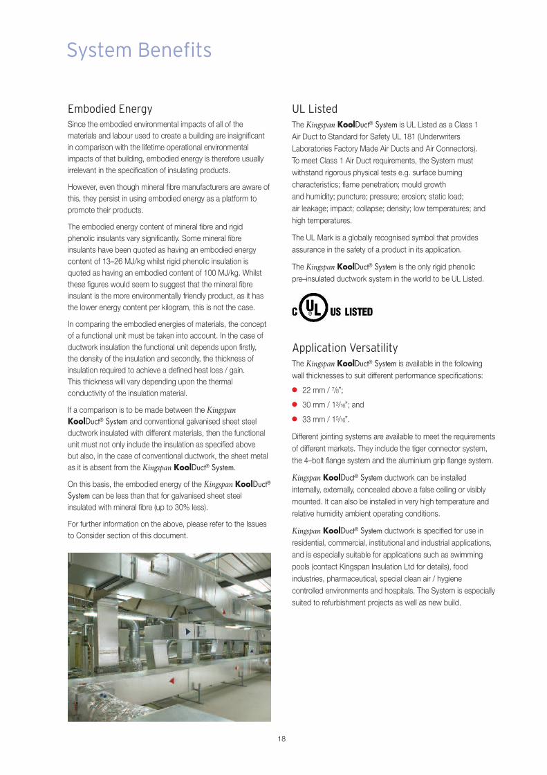
Kingspan KoolDuct® System ductwork is specified for use inresidential, commercial, institutional and industrial applications,and is especially suitable for applications such as swimmingpools (contact Kingspan Insulation Ltd for details), foodindustries, pharmaceutical, special clean air / hygienecontrolled environments and hospitals. The System is especiallysuited to refurbishment projects as well as new build.
System Benefits
UL ListedThe Kingspan KoolDuct® System is UL Listed as a Class 1Air Duct to Standard for Safety UL 181 (UnderwritersLaboratories Factory Made Air Ducts and Air Connectors).To meet Class 1 Air Duct requirements, the System mustwithstand rigorous physical tests e.g. surface burningcharacteristics; flame penetration; mould growthand humidity; puncture; pressure; erosion; static load;air leakage; impact; collapse; density; low temperatures; andhigh temperatures.
The UL Mark is a globally recognised symbol that providesassurance in the safety of a product in its application.
The Kingspan KoolDuct® System is the only rigid phenolicpre–insulated ductwork system in the world to be UL Listed.
19
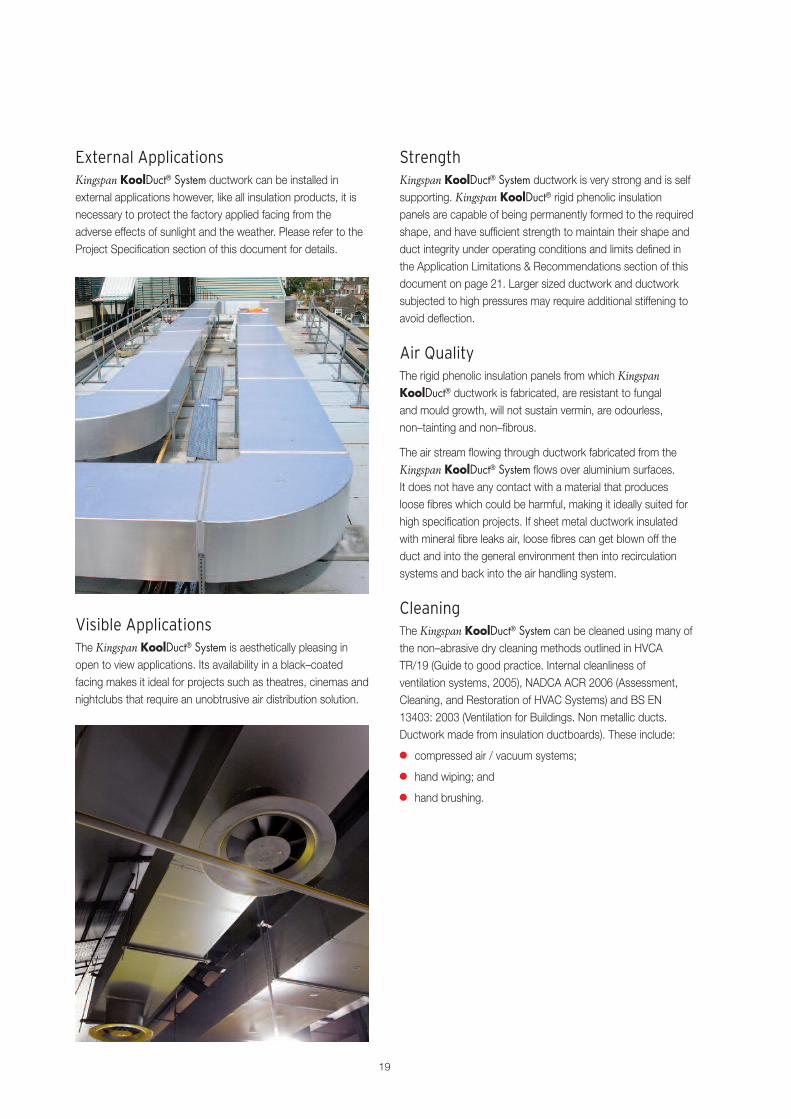
External ApplicationsKingspan KoolDuct® System ductwork can be installed inexternal applications however, like all insulation products, it isnecessary to protect the factory applied facing from theadverse effects of sunlight and the weather. Please refer to theProject Specification section of this document for details.
Visible ApplicationsThe Kingspan KoolDuct® System is aesthetically pleasing inopen to view applications. Its availability in a black–coatedfacing makes it ideal for projects such as theatres, cinemas andnightclubs that require an unobtrusive air distribution solution.
StrengthKingspan KoolDuct® System ductwork is very strong and is selfsupporting. Kingspan KoolDuct® rigid phenolic insulationpanels are capable of being permanently formed to the requiredshape, and have sufficient strength to maintain their shape andduct integrity under operating conditions and limits defined inthe Application Limitations & Recommendations section of thisdocument on page 21. Larger sized ductwork and ductworksubjected to high pressures may require additional stiffening toavoid deflection.
Air QualityThe rigid phenolic insulation panels from which KingspanKoolDuct® ductwork is fabricated, are resistant to fungaland mould growth, will not sustain vermin, are odourless,non–tainting and non–fibrous.
The air stream flowing through ductwork fabricated from theKingspan KoolDuct® System flows over aluminium surfaces.It does not have any contact with a material that producesloose fibres which could be harmful, making it ideally suited forhigh specification projects. If sheet metal ductwork insulatedwith mineral fibre leaks air, loose fibres can get blown off theduct and into the general environment then into recirculationsystems and back into the air handling system.
CleaningThe Kingspan KoolDuct® System can be cleaned using many ofthe non–abrasive dry cleaning methods outlined in HVCATR/19 (Guide to good practice. Internal cleanliness ofventilation systems, 2005), NADCA ACR 2006 (Assessment,Cleaning, and Restoration of HVAC Systems) and BS EN13403: 2003 (Ventilation for Buildings. Non metallic ducts.Ductwork made from insulation ductboards). These include:
� compressed air / vacuum systems;
� hand wiping; and
� hand brushing.

20
System Benefits
Fabricated & Installed by TrainedContractorsKingspan KoolDuct® System ductwork is fabricated andinstalled only by specially trained fabricators and installers,whose competence is continually monitored and controlled.Comprehensive training ensures uniform excellence.All registered fabricators and installers attend a specialisedtraining program to ensure that uniform quality standardsare maintained.
The course combines both theoretical and practical concepts:
� air flow dynamics, pressure and velocity;
� basic techniques in cutting and ductwork design;
� construction of a wide range of sizes and shapes;
� ductwork reinforcement, jointing and connection to sheetmetal ductwork components and plant; and
� an introduction to project cost estimation.
The nature of ductwork fabricated from the KingspanKoolDuct® System imposes certain limitations on its application,and it should not be used for the passage of solids or where itcould potentially be damaged. It can be installed in anaggressive atmosphere provided that appropriate protectivecoatings are applied and certain precautions are followed.Kingspan Insulation Ltd should always be consulted for suchapplications. While the material has excellent fire and smokeperformance, the material should not be used adjacent to hightemperature sources or where the failure of control equipmentmay give rise to high temperatures. It is also important thatcombustible matter is not allowed to collect within theductwork system, and accordingly, it is not recommended thatthe material be used in conjunction with kitchen extract andfume exhaust systems.
The Kingspan KoolDuct® System should not be used in thefollowing applications:
� kitchen extract ductwork;
� conveyance of solids;
� conveyance of hot air with temperatures in excess of 80°C /176°F;
� chemical, fume or smoke exhaust systems;
� with equipment of any type that does not include automaticmaximum temperature controls; and
� adjacent to any mechanical / electrical source of extremeheat.
Although all components of the Kingspan KoolDuct® Systemhave excellent erosion resistance characteristics, there maybe a certain amount of dust remaining within the ductworksections from the cutting and grooving operations duringfabrication and assembly. It is therefore a proceduralrecommendation that the ductwork system is blown out priorto start–up.
Nevertheless, care must be taken to ensure that the ductworksystem is cleaned to the appropriate level of cleanliness,particularly for applications in sensitive areas where a dust freeand hygiene controlled environment is required such asoperating theatres, clean rooms, hospitals, food manufacturingfacilities, pharmaceuticals, etc.
DamageThe Kingspan KoolDuct® System, like any other material andequipment on site, may be at risk of physical damage, however,the Kingspan KoolDuct® System is surprisingly robust andserious damage is rare.
Research, by independent consultants Rider Levett Bucknall,has shown that where damage occurs, onsite constructionactivity is the primary cause. This is mainly due to theunfamiliarity of site operatives with the product, so it is oftentreated in the same manner as sheet metal material, withpredictable results. The research, carried out in the UK,indicates that where operatives are made familiar with theproduct and / or specific measures are taken to identify thematerial and its properties, the risk of damage can besignificantly reduced or eliminated.
However, the Kingspan KoolDuct® System offers the flexibilityto repair localised damage in situ as opposed to replacing theentire ductwork section. Repairs can be made in aneconomical and efficient manner.
21
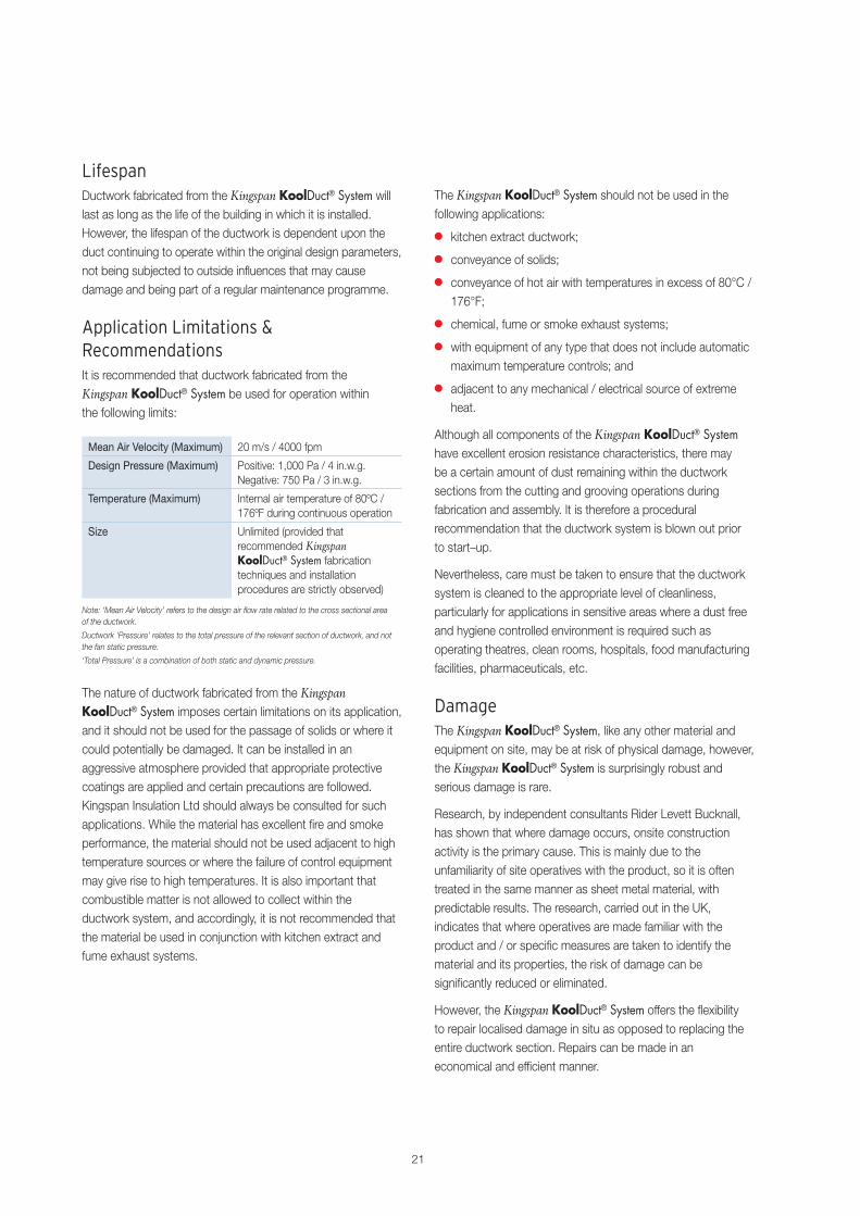
Mean Air Velocity (Maximum) 20 m/s / 4000 fpm
Design Pressure (Maximum) Positive: 1,000 Pa / 4 in.w.g.Negative: 750 Pa / 3 in.w.g.
Temperature (Maximum) Internal air temperature of 80ºC /176ºF during continuous operation
Size Unlimited (provided thatrecommended KingspanKoolDuct® System fabricationtechniques and installationprocedures are strictly observed)
Note: ‘Mean Air Velocity’ refers to the design air flow rate related to the cross sectional areaof the ductwork.
Ductwork ‘Pressure’ relates to the total pressure of the relevant section of ductwork, and notthe fan static pressure.
‘Total Pressure’ is a combination of both static and dynamic pressure.
LifespanDuctwork fabricated from the Kingspan KoolDuct® System willlast as long as the life of the building in which it is installed.However, the lifespan of the ductwork is dependent upon theduct continuing to operate within the original design parameters,not being subjected to outside influences that may causedamage and being part of a regular maintenance programme.
Application Limitations &RecommendationsIt is recommended that ductwork fabricated from theKingspan KoolDuct® System be used for operation withinthe following limits:

22
DescriptionKingspan KoolDuct® rigid phenolic insulation panels comprisea rigid phenolic insulation core faced on both sides with anextremely durable and protective low vapour permeability25 micron / 1 mil aluminium foil reinforced with a 5 mm / 0.2”glass scrim. Kingspan KoolDuct® rigid phenolic insulationpanels are also available with a 23 micron / 0.9 mil black–coated aluminium foil reinforced with a 5 mm / 0.2” glass scrimfacing on one side and the above mentioned aluminium foil onthe other.
Kingspan KoolDuct® rigid phenolic insulation panels are entirelyCFC/HCFC–free with zero Ozone Depletion Potential (ODP).
Kingspan KoolDuct® rigid phenolic insulation panels areavailable in three thicknesses to suit different performancespecifications:
� 22 mm / 7/8”;
� 30 mm / 13/16”; and
� 33 mm / 15/16”
Heat ResistanceKingspan KoolDuct® rigid phenolic insulation panels aresuitable for use in peak temperatures as high as 80ºC / 176ºFand continuous operating temperatures up to 70ºC / 158ºF.
Moisture ResistanceKingspan KoolDuct® rigid phenolic insulation panelshave a 90% (or greater) closed cell structure, which meansthey are non–wicking and highly resistant to moisturepenetration, and are particularly suitable for use in high relativehumidity environments.
Thermal PerformanceImmediately after manufacture, Kingspan KoolDuct® rigidphenolic insulation panels have a very low thermal conductivitywhich increases over a period of time as the insulation ages.The thermal conductivity then remains stable for the service lifeof the product.
The thermal conductivity of Kingspan KoolDuct® rigid phenolicinsulation panels is 0.021 W/m.K / 0.146 Btu.in/hr.ft2.ºF at10ºC / 50º F (mean), the lowest of any commonly availableinsulation material, allowing the thinnest possible insulation toachieve the required thermal performance and this is the valuethat should be used in all thermal calculations. The thermalresistances (R–value) of the different panel thicknesses areshown in the table below.
Thickness R–value
22 mm / 7/8” 1.047 m2.K/W / 6.0 ft2.hr.ºF/Btu
30 mm / 13/16” 1.428 m2.K/W / 8.1 ft2.hr.ºF/Btu
33 mm / 15/16” 1.571 m2.K/W / 8.8 ft2.hr.ºF/Btu
Environmental PerformanceKingspan KoolDuct® rigid phenolic insulation panelsare manufactured without the use of CFCs/HCFCsand have zero Ozone Depletion Potential (ODP).
Kingspan Insulation has achievedBS EN ISO 14001: 2004(Environmental management systems.Requirements with guidance for use),which insists on year on year environmental improvements inthe performance of any company that achieves the standard.
Product Data
23
Fire & Smoke PerformanceKingspan KoolDuct® rigid phenolic insulation panels have aresistance to burning and spread of flame far superior to thatof any other cellular plastic insulation. In addition, there isan almost complete absence of smoke when subjected to aflame source.
Kingspan KoolDuct® rigid phenolic insulation panels have beentested by independent laboratories. The tests shown in thetable below have been successfully passed.
Standard Description
BS 476–6: 1989 Fire tests on building materials andstructures. Method of test for firepropagation for products
BS 476–7: 1997 Fire tests on building materials andstructures. Method for classification ofthe surface spread of flame of products
BS 6401: 1983 Method for measurement, in thelaboratory, of the specific optical densityof smoke generated by materials
AS/NZS 1530–3: 1999 Methods for fire tests on buildingmaterials, components and structures –Simultaneous determination ofignitability, flame propagation, heatrelease and smoke release
ASTM E 84–08a Standard Test Method for SurfaceBurning Characteristics of BuildingMaterials
UL 723 Test for Surface Burning Characteristicsof Building Materials
UL 181 Burning Test
Defence Standard 02–713 Determination of the Toxicity Index ofthe Products of Combustion from SmallSpecimens of Materials
Based on the results of the tests described above,Kingspan KoolDuct® rigid phenolic insulation panels:
� are classified as Class 0 to the Building Regulations inEngland & Wales, Northern Ireland and the Republic ofIreland, and Low Risk to the Building Standards in Scotland;
� meet the requirements of the fire hazard properties as setout in AS 4254: 2002 to comply with the Building Code ofAustralia (BCA) 2008 Specification C1.10–9;
� enable (as part of a comprehensive test program) theKingspan KoolDuct® System to be UL Listed as a Class 1Air Duct to Standard UL 181 in accordance with NFPA(National Fire Protection Association) Standards 90A & 90B;and
� are approved by the UAE Ministry of Interior DubaiCivil Defense for use in the fabrication of pre–insulated airdistribution ductwork systems.
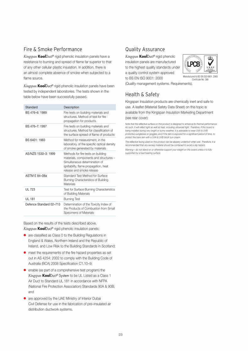
Quality AssuranceKingspan KoolDuct® rigid phenolicinsulation panels are manufacturedto the highest quality standards undera quality control system approvedto BS EN ISO 9001: 2000(Quality management systems. Requirements).
Health & SafetyKingspan Insulation products are chemically inert and safe touse. A leaflet (Material Safety Data Sheet) on this topic isavailable from the Kingspan Insulation Marketing Department(see rear cover):
Note that the reflective surface on this product is designed to enhance its thermal performance.As such, it will reflect light as well as heat, including ultraviolet light. Therefore, if this board isbeing installed during very bright or sunny weather, it is advisable to wear UVA & UVBprotective sunglasses or goggles, and if the skin is exposed for a significant period of time, toprotect the bare skin with a UVA & UVB block sun cream.
The reflective facing used on this product can be slippery underfoot when wet. Therefore, it isrecommended that any excess material should be contained to avoid a slip hazard.
Warning – do not stand on or otherwise support your weight on this board unless it is fullysupported by a load bearing surface.
Manufactured to BS EN ISO 9001: 2000Certificate No. 388

IntroductionIn the construction industry, developers, funding bodies andmanufacturers have historically focused on achieving a lowcapital cost in order to improve profits.
However, for buildings that are let / rented out under contractswhich include ongoing maintenance and services provision bythe lessor, or for buildings developed for forward thinkingclients, operating cost can be as just important as capital costin building design.
‘Whole life’ costing takes account of the total cost of an itemover its life, including durability, energy savings andmaintenance, as well as initial purchase price.
Review of the AlternativesKingspan Insulation commissioned independent consultants,Cyril Sweett, to carry out an analysis of the ‘whole life’ costs ofdiffering UK HVAC ductwork specifications*. Cyril Sweett’s initialwork narrowed the analysis of ‘whole life’ cost down to costsassociated with installation, durability, energy use, cleaning, riskof mechanical damage and damage repair; the findings ofwhich are described herein.
The installed cost of ductwork fabricated from the KingspanKoolDuct® System was found to be cheaper than that ofgalvanised sheet steel ductwork.
Cyril Sweett concluded that Kingspan KoolDuct® rigid phenolicinsulation panels consist of a densely cross linked structurewhich does not readily break down. They also noted thatindependent testing has shown that the thermal performanceof Kingspan Insulation rigid phenolic insulation panels are notprone to long term degradation and that they maintain theirdesigned performance throughout a ‘whole life’ 30 year period.
Cyril Sweett endorsed the contents of a study carried out byindependent consultants Rider Levett Bucknall, based on theresults of research carried out by BSRIA, to investigate theestimated effect on fan power of different duct air leakagerates. The research showed that the Kingspan KoolDuct®
System can save over 30% on the annual electricity cost ofrunning a fan compared with the performance of galvanisedsheet steel ductwork.
Cyril Sweett’s research showed that ductwork fabricated fromthe Kingspan KoolDuct® System is marginally more expensiveto clean than galvanised sheet steel ductwork.
Cyril Sweett’s own research into ductwork maintenanceshowed that ductwork fabricated from the Kingspan KoolDuct®
System suffers minimal damage and thus requires minimalrepairs, particularly where ductwork is installed within a ceilingvoid. In circumstances where a repair is required, it concludedthat ductwork fabricated from the Kingspan KoolDuct® Systemcan be repaired quickly by simply replacing the damagedarea whereas with sheet metal ductwork, the entire sectionwould need to be replaced, with the insulation installed as asecond operation.
Once the above data had been analysed, the capital, operatingand ‘whole life’ costs were calculated.
Whole Life CostsSummaryThe Kingspan KoolDuct® System must be considered as theproduct of choice for HVAC ductwork systems in projectswhere ‘whole life’ costing is a requirement since:
� installation of the Kingspan KoolDuct® System can save over21% on capital cost; and
� over a 30 year life cycle, the Kingspan KoolDuct® Systemcan also make a saving of over 20% on operating costs.
24
Issues to Consider
Kingspan Insulated GalvanisedTechnology KoolDuct® Sheet Steel
Capital Cost (£) 37,000 47,154Saving (%) 21.5Operating Cost (£)(Over 30 yrs)
67,672 85,058
Saving (%) 20.4‘Whole Life’ Cost (£) 104,672 132,212‘Whole Life’ Saving (%) 20.8
Note the costs detailed in this report are based on the use of the Kingspan KoolDuct® Systemconstructed with 22 mm / 7/8” rigid phenolic insulation panels and the aluminium grip flangejointing system versus 40 mm / 19/16 mineral fibre insulated galvanised sheet steel ductwork.
*A copy of the Cyril Sweett Limited report is available upon request from the KingspanInsulation Marketing Department on +44 (0) 870 733 8333.
Results of the AnalysisCyril Sweett based the comparison of capital cost on asystem comprising 308 m / 1010 ft of ductwork of a widevariety of dimensions.
The capital cost of insulated galvanised sheet steel ductworkwas £47,154 versus £37,000 for ductwork fabricated from theKingspan KoolDuct® System.
Thus, the Kingspan KoolDuct® System can provide a capitalcost saving of 21.5% (see the table below).
Cyril Sweett then calculated the operating cost of the twotechnologies over a 30 year period, taking into accountenergy use, maintenance, cleaning and changes due to wearand tear (churn).
Over a 30 year period, the system operating cost for insulatedgalvanised sheet steel technology was £85,058 versus £67,672for the Kingspan KoolDuct® System. Thus, the KingspanKoolDuct® System can provide an operating cost saving of20% (see the table below).
Combining capital and operating costs to give a ‘whole life’cost yields a total saving of £27,540. Thus the KingspanKoolDuct® System can provide an overall ‘whole life’ costsaving of 21%.
25
Economy of Duct DesignA ductwork system accounts for a substantial portion of theoverall cost of a building’s HVAC system – potentially in excessof a third of the total cost. Careful and attentive planning duringthe design stage of a ductwork system can yield a significantreduction in its overall cost.
There are two factors in particular that can have a considerableimpact:
� the total number of special pieces / fittings (pieces otherthan straight sections); and
� the aspect ratio of the ductwork sections.
Special pieces / fittings such as elbows, reducers, and offsets,etc. require considerably more labour (and material to a certainextent) to construct than straight sections. While all ductworksystems will require a certain quantity of special fittings, theirusage should be minimised. Ideally, the system should followthe straightest possible route.
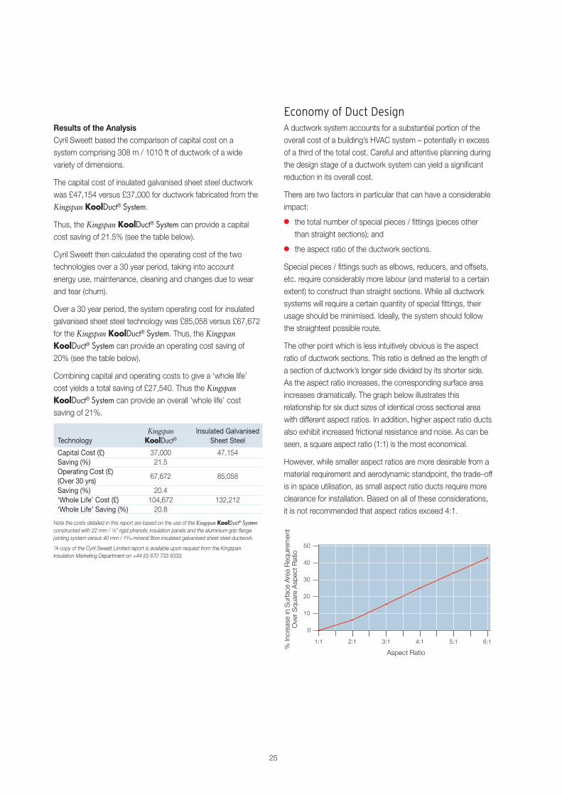
The other point which is less intuitively obvious is the aspectratio of ductwork sections. This ratio is defined as the length ofa section of ductwork’s longer side divided by its shorter side.As the aspect ratio increases, the corresponding surface areaincreases dramatically. The graph below illustrates thisrelationship for six duct sizes of identical cross sectional areawith different aspect ratios. In addition, higher aspect ratio ductsalso exhibit increased frictional resistance and noise. As can beseen, a square aspect ratio (1:1) is the most economical.
However, while smaller aspect ratios are more desirable from amaterial requirement and aerodynamic standpoint, the trade–offis in space utilisation, as small aspect ratio ducts require moreclearance for installation. Based on all of these considerations,it is not recommended that aspect ratios exceed 4:1.

26
Issues to Consider
Cadogan Hall, Sloane Square,LondonThe loadings imposed by thenew theatre ventilation systemwere minimised with theKingspan KoolDuct® System,removing the need for additionalsupport members, which wouldhave been difficult to installwithin the existing historicstructural element.
Virgin Roof Gardens,Kensington, LondonThe light weight of the KingspanKoolDuct® System enabled thenew extension structure toaccommodate the load of theexisting structure in addition tothe considerable network ofductwork, eliminating the needfor a substantial redesign.
WeightSummary� The introduction of the Kingspan KoolDuct® System to a
project can save money and add value.
� The System provides the only practicable solution forsome projects.
� The System can function to ensure project viability.
� For the above reasons, the Kingspan KoolDuct® Systemshould be an automatic consideration for refurbishmentprojects.
Current Practice� HVAC systems are commonly added to built environments
which have not previously incorporated such systems.
� Existing building structures commonly have insufficient loadcapacities for new service loads.
� HVAC ductwork is traditionally constructed using galvanisedsheet steel insulated with mineral fibre, which is installed asa separate construction activity.
� Time constraints mean that projects may start before thedesign process is complete.
� The ductwork material is commonly not considered until latein a project’s design process.
� Those who are not intimate with a project’s constraintscommonly select the ductwork material.
� Detailed surveys of existing structures to the level requiredto plan service layouts are commonly unavailable beforeconstruction commences.
� Services design and design co–ordination commonly occursconcurrently with the construction process, often requiringsignificant changes to the ductwork configuration.
� Delays are commonly caused by unforeseen obstaclesdiscovered only once construction starts and full exposureof the structure occurs.
� Delays are commonly caused by design changes that arerequired during the construction period.
Review of the AlternativesKingspan Insulation commissioned an independent review ofsix UK case studies by independent consultants, Rider LevettBucknall*. The purpose of this review was to examine insulatedsheet steel ductwork and the Kingspan KoolDuct® System, theirrelative performance with regards to weight and the benefitsthat this can incur.
A series of refurbishment or fit out projects that used theKingspan KoolDuct® System were reviewed. Data was collectedby interviewing personnel involved, including the projectmanagers, architects, structural engineers, services engineersand quantity surveyors, contractors, servicessub–contractors and ductwork sub–sub–contractors.
Almost without exception, the light weight of the KingspanKoolDuct® System had an impact on the project, contributingto its success through a reduction of the potential project costor by directly influencing its feasibility.
In some instances, the Kingspan KoolDuct® System hadbeen selected at the outset because of its known propertiesand the project constraints. Generally however, it was not aninitially specified choice but was subsequently selected toovercome problems that arose during the development of thedetailed design.
27
The explanation for this is that, for historical reasons, themajority of ductwork in the UK construction industry isfabricated using galvanised sheet steel with the insulationsubsequently installed, if required. The selection of ductworkmaterial is therefore generally assumed. Additionally, theconstruction project client’s specification for ductwork isnormally limited to a set of performance criteria rather than aspecific material. The actual selection of the ductwork materialis made by the mechanical services sub–contractor or, moreoften, its ductwork sub–sub–contractor. Neither of theseorganisations derives a direct benefit from the selection of theKingspan KoolDuct® System. Indeed, because of existingmanufacturing setups, it may be disadvantageous to moveaway from the existing specification norms. With the materialselection so far removed from those dealing with the specificproject constraints, it is not surprising that the selection of themost appropriate material often occurs well into the designprocess or, to the client’s disadvantage, not at all.
On the reviewed projects, the main reason for the selection ofthe Kingspan KoolDuct® System was that it could overcomesevere constraints on structural loadings. In thesecircumstances, the selection of the Kingspan KoolDuct®
System, over a galvanised sheet steel ductwork system, wasoften the only realistic choice, the alternative normally being theintroduction, at potentially significant additional cost, ofsecondary steel supports to transfer service loads back to thestructure. In some projects, even this option was not availablefor example, where buildings contained features of historic orarchitectural importance that could not be obscured by theintroduction of new structural members.
An additional attribute contributing to the selection of theKingspan KoolDuct® System was its ability to be delivered tosite in a flat form and for the ductwork sections to be assembledonsite or even, in extreme situations, in their final locations.For sites with extreme space constraints, this characteristicbecame crucial to the success of the project. The pre–insulatednature of the Kingspan KoolDuct® System also removed theneed for access space required for the subsequent insulationinstallation, which proved to be another valuable advantage inthe constrained environment of existing buildings.
The flexibility of being able to fabricate the ductwork onsitealso proved advantageous in rapidly dealing with unexpectedchanges to the design required by the uncovering of unforeseenobstructions, or as a result of other design amendments.This feature played an important part in enabling contractprogrammes to be maintained whereby the replacementof fabricated and delivered galvanised sheet steel ductworkwould have taken 2–3 weeks.
In all situations, the lightweight nature of the KingspanKoolDuct® System made the installation process easier.A further, more direct result of the lightweight properties wasthat the material had a greatly reduced hazard potential. Riskassessments, required for construction operations, were lessonerous than those associated with installing the far heavieralternative materials and hence the safety strategies andprotection measures that were adopted were also less onerous.
*A copy of the Rider Levett Bucknall report is available upon request from the KingspanInsulation Marketing Department on +44 (0) 870 733 8333.
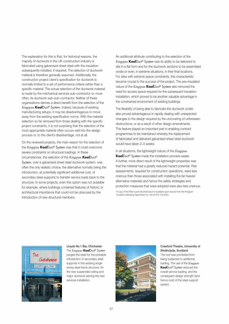
Lloyds No.1 Bar, ChichesterThe Kingspan KoolDuct® Systempurged the need for the probableintroduction of secondary steelsupports in this existing singlestorey steel frame structure, forthe new suspended ceiling andmajor ductwork serving the newservices installation.
Crawford Theatre, University ofStrathclyde, ScotlandThe roof was prohibited frombeing subjected to additionalloading. The use of the KingspanKoolDuct® System reduced theoverall service loading, and theconsequent design strength (andhence cost) of the steel supportsystem.

Review of the AlternativesKingspan Insulation commissioned an independent review ofsix UK case studies by independent consultants, Rider LevettBucknall*. The purpose of this review was to examine insulatedsheet metal ductwork and the Kingspan KoolDuct® System,their relative performance with regards to speed of installationand the benefits that this can incur.
Data was collected by interviewing personnel involved includingthe project managers, architects, structural engineers,services engineers and quantity surveyors, contractors, servicessub–contractors and ductwork sub–sub–contractors.
A series of interviews were also undertaken with maincontracting organisations, to review how the ductworkinstallation activity generally fitted within the overall constructionprogramme and its interaction with preceding, concurrent andsucceeding activities.
In the UK, the Kingspan KoolDuct® System can be constructedin ductwork sections up to 3 m / 10 ft long, provided the crosssectional dimensions of the duct are less than 1.2 m / 3.94 ft.More importantly, because of its comparative light weight,several sections can be jointed together on the floor level andinstalled in a single operation. It was commonly found thatlengths of up to 9 m / 30 ft were assembled and installed in thismanner, with instances where the total length raised in oneoperation was up to 15 m / 50 ft long.
Ductwork installers reported that Kingspan KoolDuct® Systemductwork could be installed at an average of three times therate of equivalent sheet metal ductwork. Although every schemewill be different and there are rarely exactly comparablecircumstances, the average installation productivity for atwo–man team is 7–9 m/day / 23–30 ft/day for sheet metalductwork, and 23–25 m/day / 75–82 ft/day for KingspanKoolDuct® System ductwork. These figures exclude the timerequired to install the ductwork insulation to sheet metalductwork; a process not required by the Kingspan KoolDuct®
System of pre–insulated ductwork.
Installation SpeedSummary� The Kingspan KoolDuct® System can be installed up to
three times faster than sheet metal ductwork.
� Construction periods can be reduced where ductwork isa critical path activity.
� The risk and extent of time extensions on projects canbe reduced.
� For the above reasons, the Kingspan KoolDuct® Systemshould be an automatic consideration where projectdurations are a key issue and ductwork is a critical pathactivity.
Current Practice� HVAC systems are a common feature of both new build and
refurbishment construction works.
� HVAC ductwork is traditionally constructed using galvanisedsheet steel insulated with mineral fibre, which is installed asa separate construction activity.
� The ductwork material is commonly not considered until latein a project’s design process.
� Those who are not intimate with a project’s constraintscommonly select the ductwork material.
� Services design and design co–ordination commonly occursconcurrently with the construction process, often requiringsignificant changes to the ductwork configuration.
� Ductwork is not normally considered as an area ofprogramme risk or where there is scope for improvement inactivity duration.
� Delays are commonly caused by unforeseen obstaclesdiscovered only once construction starts and full exposureof the structure occurs.
� Delays are commonly caused by design changes that arerequired during the construction period.
28
Issues to Consider
House of Fraser, King WilliamStreet, LondonThe ability to fabricate KingspanKoolDuct® ductwork onsiteproved invaluable when unknownobstructions were revealed.The extensive amounts andcritical nature of the ductworkinstallation meant that the fasterinstallation speed saved weekson the programme.
Chelsea Bridge, Wharf, LondonAt three times the plannedproductivity, the installers wereable to achieve installations to10–12 apartments per day.The ductwork had been a criticalpath activity but the installationspeed was so much faster thanplanned that it came off thecritical path.
Where the projects involved a significant amount of air handlingductwork, the period of time during which the activity wascritical could be significant, and the introduction of theKingspan KoolDuct® System can operate to reduce projectdurations by several weeks. If the project is restricted to thesimple refurbishment, replacement or retro fitting of an airhandling / ventilation system then the full advantage of thefaster installation speed can be available.
However, for most projects incorporating industry standard fancoil air conditioning systems, the ductwork remains on thecritical path for only a short period of time. On these projectsthe research indicated that pipework and its insulation normallyproves to be the limiting factor, preventing maximum advantageof the Kingspan KoolDuct® System’s faster installation times.
The faster installation speeds were achieved with the samelevel of resources as sheet metal ductwork. This helped tocreate a lower density of site labour for ductwork installation,and thus increased the efficiency and productivity for othertrades and activities by reducing pressure on space and sitefacilities. This advantage was further enhanced by removing therequirement for an insulation activity and its associated labour.
The faster installation speeds permitted consideration to begiven to re–sequencing other work activities to allow for moreeconomic and less disruptive work practices. On at least twoprojects, this approach allowed the internal partitions to beconstructed around the ductwork rather than cutting holesthrough the completed elements of the new structure.
The flexibility of being able to fabricate the ductwork onsite alsoproved advantageous in rapidly dealing with unexpectedchanges to the design required by the uncovering ofunforeseen obstructions, or as a result of other designamendments. This feature played an important part in enablingcontract programmes to be maintained whereby thereplacement of fabricated and delivered galvanised sheet steelductwork would have taken 2–3 weeks.
In some instances the Kingspan KoolDuct® System hadbeen selected at the outset because of its known propertiesand the project constraints. Generally however, it was not aninitially specified choice but was subsequently selected toovercome problems that arose during the development of thedetailed design.
In summary, the majority of the individuals interviewed statedthat the Kingspan KoolDuct® System had an impact on theprogramme of the projects on which they were involved.The savings were in the form of shorter initial contract durationsand / or reductions in, or removal of the need to extendcontract periods as a result of design developments andvariations arising during the construction period.
Due to the confidential nature of financial and programminginformation, together with the wide variety of project types thatwere reviewed, it is not possible to provide a simple answer tothe question regarding the amount of the monetary savingsavailable. Based on the projects reviewed the savings couldrange from £5,000–£50,000. In no instance was it found thatthe introduction of the Kingspan KoolDuct® System resulted ina potential increase in the contract value.
*A copy of the Rider Levett Bucknall report is available upon request from the KingspanInsulation Marketing Department on +44 (0) 870 733 8333.
29
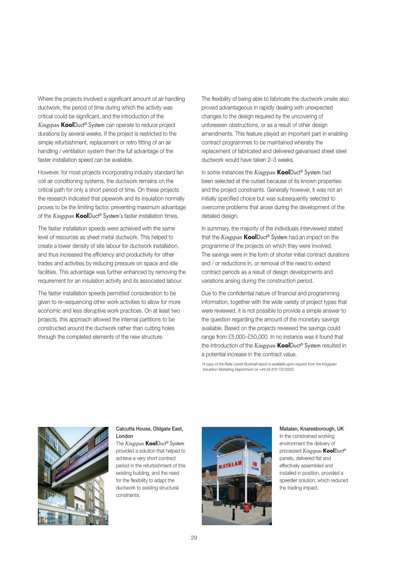
Calcutta House, Oldgate East,LondonThe Kingspan KoolDuct® Systemprovided a solution that helped toachieve a very short contractperiod in the refurbishment of thisexisting building, and the needfor the flexibility to adapt theductwork to existing structuralconstraints.
Matalan, Knaresborough, UKIn the constrained workingenvironment the delivery ofprocessed Kingspan KoolDuct®panels, delivered flat andeffectively assembled andinstalled in position, provided aspeedier solution, which reducedthe trading impact.
30
Issues to Consider
Energy & Running CostsSummary� The use of the Kingspan KoolDuct® System can save over
30% of the energy required to run a fan in an HVAC system.
� Its use can reduce the size of fan required in a HVACsystem – this reduction in fan size can yield a 10% saving inits capital cost.
� For the above reasons, the Kingspan KoolDuct® Systemshould be an automatic consideration for all HVAC ductworkspecifications.
Current Practice� HVAC ductwork systems are a common feature of new
build and refurbishment construction works.
� HVAC ductwork is traditionally constructed using galvanisedsheet steel insulated with mineral fibre which is installed as aseparate construction activity.
� The ductwork material is commonly not considered until latein a project’s design process.
� Little or no attention is paid to the effects that ductworkair leakage has on fan energy use and carbon dioxideemissions.
� Little or no attention is paid to the potential for downsizingfans and reducing capital costs on the back of lowerductwork air leakage rates.
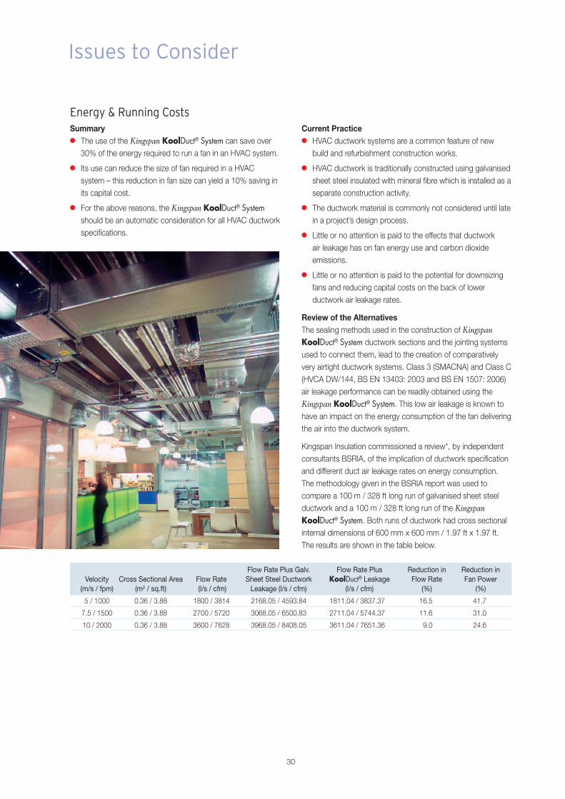
Review of the AlternativesThe sealing methods used in the construction of KingspanKoolDuct® System ductwork sections and the jointing systemsused to connect them, lead to the creation of comparativelyvery airtight ductwork systems. Class 3 (SMACNA) and Class C(HVCA DW/144, BS EN 13403: 2003 and BS EN 1507: 2006)air leakage performance can be readily obtained using theKingspan KoolDuct® System. This low air leakage is known tohave an impact on the energy consumption of the fan deliveringthe air into the ductwork system.
Kingspan Insulation commissioned a review*, by independentconsultants BSRIA, of the implication of ductwork specificationand different duct air leakage rates on energy consumption.The methodology given in the BSRIA report was used tocompare a 100 m / 328 ft long run of galvanised sheet steelductwork and a 100 m / 328 ft long run of the KingspanKoolDuct® System. Both runs of ductwork had cross sectionalinternal dimensions of 600 mm x 600 mm / 1.97 ft x 1.97 ft.The results are shown in the table below.
Flow Rate Plus Galv. Flow Rate Plus Reduction in Reduction inVelocity Cross Sectional Area Flow Rate Sheet Steel Ductwork KoolDuct® Leakage Flow Rate Fan Power
(m/s / fpm) (m2 / sq.ft) (l/s / cfm) Leakage (l/s / cfm) (l/s / cfm) (%) (%)
5 / 1000 0.36 / 3.88 1800 / 3814 2168.05 / 4593.84 1811.04 / 3837.37 16.5 41.7
7.5 / 1500 0.36 / 3.88 2700 / 5720 3068.05 / 6500.83 2711.04 / 5744.37 11.6 31.0
10 / 2000 0.36 / 3.88 3600 / 7628 3968.05 / 8408.05 3611.04 / 7651.36 9.0 24.6
BSRIA’s methodology demonstrated that the KingspanKoolDuct® System can save 31% of the energy required torun a fan in a HVAC system with a typical design flow rateof 7.5 m/s / 1500 fpm. These savings can be greater for lowerdesign flow rates.
Kingspan Insulation commissioned a review*, by independentconsultants Rider Levett Bucknall, of the implications ofreduced fan power on actual energy usage.
Rider Levett Bucknall concluded that for a 100 m / 328 ft longrun of ductwork, with cross sectional internal dimensionsof 600 mm x 600 mm / 1.97 ft x 1.97 ft and an air velocity of7.5 m/s / 1500 fpm, the Kingspan KoolDuct® System couldsave 3,100 kW.hr / 10.58 x 10⁶ Btu per annum.
This energy saving equates to a saving of 1.3 metric tonnes /1.28 long tons of CO2 equivalent emissions per annum.
Kingspan Insulation commissioned a further review*, by RiderLevett Bucknall, of the implications of reduced fan power onfan size and capital cost. Their conclusions are shown below.
Typically a fan will be sized on the amount of air that is neededto deliver the required volume of air, taking into accountpressure drop. A multiplier (normally 10%) will then be applied,to take into account the flexibility required due to the actualresistance and final installation. If the system does not leak asmuch as is permitted under the air leakage tests (which aremaximum figures,) then the fan is commissioned to run at alower speed by using inverter drives or belt and pulley changes.
Air leakage directly relates to the size of the fan required todeliver the designed air flow in a duct. The Kingspan KoolDuct®
System has a lower leakage rate than galvanised sheetsteel ductwork – 11.6% lower for a 100 m / 328 ft long runof ductwork with cross sectional internal dimensions of600 mm x 600 mm / 1.97 ft x 1.97 ft and an air velocity of7.5 m/s / 1500 fpm (refer to the table on the previous page).Therefore, by using the Kingspan KoolDuct® System in lieu of agalvanised sheet steel ductwork system, an 11.6% reduction infan size could be achieved for a duct of this size and velocity.
A duct with these characteristics would typically conveyapproximately 2.5 m3/s / 5297 cfm of air (at a standardatmospheric pressure and temperature as per CIBSE guide,Clause 4.2) possibly serving a minimum fresh air fan coilunit system.
For a comparable system using the Kingspan KoolDuct®
System as the ductwork specification, an 11.6% reduction onthe size of the fan is achievable due to the lower air leakagerate therefore the fan duty, for the Kingspan KoolDuct® System,would be 2.2 m3/s / 4662 cfm.
The respective costs in GBP (£) of a supply air fan within an airhandling unit for the two systems are:
� Galvanised Sheet Steel Ductwork (2.5 m3/s / 5297 cfm)£2000
� Kingspan KoolDuct® System ductwork (2.2 m3/s / 4662 cfm)£1800
This equates to an approximate capital cost saving of 10%.
NB the energy and capital costs included in this paper arebased on test results carried out on a 100 m / 328 ft longstraight piece of ductwork. In practice, air leakage is more likelyto occur where ductwork changes direction and therefore wesuggest that leakage tests are carried out on an installedsystem to ratify the findings of this study. Secondly, in order toachieve the fan energy and capital costs that are available,current engineering practice needs to be reviewed.
*Copies of the CIBSE and Rider Levett Bucknall reports are available upon request from theKingspan Insulation Marketing Department on +44 (0) 870 733 8333.
31
The measure of the rate at which heat flows through an insulantis known as its thermal conductivity or k–value. The lower thek–value, the better the insulant is at restricting heat flow.Kingspan KoolDuct® rigid phenolic insulation panels have ak–value of 0.021 W/m.K at 10ºC mean / 0.146 Btu.in/ft2.hr.ºF at50ºF mean, which offers the best performance of all commonlyutilised insulating materials.
The k–value for an insulant is measured with the material underlaboratory conditions. In–service applications rarely if everreplicate these conditions and it is therefore important toconsider physical factors which may alter this state and lead toan increase in the k–value of the material and thus increasedprimary energy usage.
The k–values of commonly used insulants typically lie in therange of 0.021 to 0.046 W/m.K at 10ºC / 0.146 Btu.in/ft2.hr.ºFto 0.319 Btu.in/ft2.hr.ºF at 50ºF mean. These measurementsrelate to the material at a specific temperature and in a drystate. If moisture is introduced into the insulant, the measuredconductivity will increase very significantly. If moisture is able topenetrate to the point of saturation or near saturation, thethermal efficiency of the insulant can be destroyed. This is dueto three main mechanisms:
� the k–value of water is 0.58 W/m.K at 10ºC / 4.03Btu.in/ft2.hr.ºF at 50ºF, which is significantly higher than thatof all commonly used insulants – thus if moisture is presentthe overall thermal conductivity of the material will increasesignificantly depending on the quantity of water absorbed;
� moisture moving through or within an insulant can effectivelyabsorb heat from the warm side and then dissipate it on thecold side of the assembly; and
� a closed assembly in which moisture is trapped within theinsulant between impermeable layers (such as withaluminium foil faced duct insulation) can be subject toadditional ‘phase change’ heat losses.
These heat losses occur when heat from the warm side of theinsulant vapourises the trapped moisture which then diffusesthrough the insulant to the cold side. When it reaches the coldside the heat is dissipated, the vapour condenses back intoliquid form and flows back to the warm side of the insulation.This is a closed cycle which could theoretically continueindefinitely if acceptable environmental conditions prevail andleads to significant additional heat losses through the insulant.
Moisture can be present in insulation due to:
� penetration through the weather protection; and
� vapour penetration through the vapour barrier jacket leadingto interstitial condensation on below ambient ductwork,particularly in tropical climates where conditions are warmand wet on the outside and cold and dry on the inside ofthe ductwork.
32
Issues to Consider
Moisture & Exacerbated Heat Loss / Gain
Mineral fibre has little resistance to water vapour penetrationwhich may occur if it is installed with an imperfectly sealedvapour barrier jacket or if the vapour barrier jacket is damagedin use. This can result in:
� condensation formation on below ambient temperatureductwork;
� corroded ductwork;
� dripping services and spoiled ceilings;
� mould growth and bad odour;
� building fabric damage;
� increased energy consumption; and
� expensive repair works causing disruption to business.
Different types of insulant absorb differing levels of moisture.The level of moisture absorbed also affects varying types ofinsulants in different ways. Whilst closed cell materials, e.g.Kingspan KoolDuct® rigid phenolic insulation panels, may havelow water vapour permeability characteristics, fibrous insulatingmaterials can absorb considerable quantities of water which,whilst present can adversely affect the thermal conductivity andthe effectiveness of the insulation.
Since rigid phenolic insulation has a 90% (or greater) closed cellcontent, moisture is not readily absorbed as it must penetratethrough the cell walls to enter the material. This does not readilyoccur unless the cell walls have been damaged. If it doesoccur, the amount of moisture absorption is generally very lowand is effectively eliminated if the insulant is faced with animpervious material such as aluminium foil.
If moisture is able to penetrate the outer damaged cells of rigidphenolic insulation where there is no impervious facing material,it will increase the overall thermal conductivity of the productslightly. However, it will not lead to any long term degradation ofthe product and will fully dry out once favourable environmentalconditions exist.
Kingspan KoolDuct® rigid phenolic insulation panels have analuminium foil facing on both sides which makes them highlyresistant to moisture penetration.
The risk of moisture penetration from damage to the aluminiumfoil vapour barrier jacket is considerably reduced as the rigidphenolic insulation core of the Kingspan KoolDuct® panels is of‘closed cell’ construction.
Vapour seal tape can be easier to apply to Kingspan KoolDuct®
rigid phenolic insulation panels with a more secure and efficientseal.
Mineral fibre insulants are open structured materials which relylargely on entrapped still air for much of their insulating power.They can have little long term resistance to water and may haveno resistance to vapour flow. Thus, the potential for moistureabsorption can be very high if the factory applied vapour barrierjacket is either damaged or inadequately sealed.
Research has been undertaken into the effect of moisture ofmineral fibre insulants by Achtziger and Cammerer of FIW inGermany. Their research concluded that 1% moisture contentby volume within mineral fibre can increase the thermalconductivity of the material by 36–107% with 4 of the 5 samplestested falling within the 95–107% increase range(Forschungsvorhaben Nr.815–80.01.83–4 contained within CENTC 88 WG 4–N484). Such increases in the thermal conductivityof the material could have a very significant impact on the levelof heat loss or gain on a building services installation.
33

SustainabilityIn the past, erroneously, the relative environmental sustainabilityof insulation materials has been compared on the basis ofembodied energy and ozone depletion potential. It is nowrecognised that a much wider basket of embodiedenvironmental impacts (including those caused by theirembodied energy), rather than embodied energy alone,is the only credible tool of comparison. Time has also annulledozone depletion potential as an issue, for example in theEU, all insulation materials are now banned from usingCFCs and HCFCs.
For buildings designed to today’senergy use requirements it is nowalso known that the embodiedenvironmental impacts of all of thematerials and labour used to create abuilding are insignificant in comparisonwith the lifetime operationalenvironmental impacts of that buildingand so are of very limited importance.Since it is operational energy use thatcreates the vast majority of operationalenvironmental impact, saving energy byspecifying the lowest heat loss / gain and ductwork air–leakagestandards possible is the most environmentally sustainableaction to take. A ground breaking study “Insulation forEnvironmental Sustainability” has been published by BING onthis and related issues. This report, written by XCO2 connisbee,is freely available from Kingspan Insulation (see rear cover).
Furthermore, one of the most neglected facts aboutenvironmentally sustainable buildings is that the longevity oftheir standards of operational energy use, and therefore thelongevity their operational environmental impacts, is critical.The performance of some insulants, such as mineral fibre, candeteriorate rapidly if exposed to water penetration, airmovement or compression. This may increase operationalenergy use and hence compromise the environmentalsustainability of the finished building to an alarming degree.Other insulation materials, such as rigid phenolic insulation areconsiderably less vulnerable to any of these problems thanmineral fibre.
In summary, designers should:
(a) specify the best heat loss / gain and ductwork air leakagestandards possible, regardless of insulation / ductwork type;
(b) design out the risk of their chosen insulant / ductworksystem not performing as specified; and
(c) if the latter is not possible, choose an insulant / ductworksystem that is at low risk of failure e.g. rigid phenolicpre–insulated ductwork.
The Kingspan KoolDuct® System is therefore arguably the mostenvironmentally sustainable ducting technology available.
However, manufacturers should not rest on their laurels, it is amatter of social responsibility to be open and honest about theenvironmental impact of the manufacture of a product, and afull Life Cycle Analysis (LCA) based on a much wider basket ofenvironmental impacts, rather than embodied energy alone, isrecognised as the preferred tool to achieve this.
Kingspan Insulation was the first insulation manufacturer tocomplete and openly publish an independently certifiedEcoprofile (a type of LCA) on one of its product ranges.This was carried out by the Building Research Establishment(BRE). Kingspan Insulation is currently completing a BREEcoprofile of its rigid phenolic insulation products, includingKingspan KoolDuct® rigid phenolic insulation panels.
But there is far more to sustainability than whether or not aproduct, process or company affects the environment in apositive or a negative way. A company can and shoulddemonstrate its financial viability and social responsibility, aswell as ensure that its materials and methods do not addunduly to the burden placed on the planet.
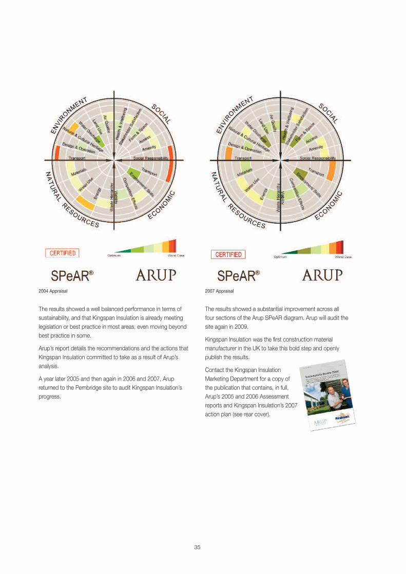
In 2004 Kingspan Insulation put the manufacture of its productsat its Pembridge, Herefordshire facility in the UK through arigorous independent appraisal of its economic, social,environmental and natural resource impacts using Arup’sSPeAR® tool. These products include Kingspan KoolDuct®
rigid phenolic insulation panels.
34
Issues to Consider
35
The results showed a well balanced performance in terms ofsustainability, and that Kingspan Insulation is already meetinglegislation or best practice in most areas, even moving beyondbest practice in some.
Arup’s report details the recommendations and the actions thatKingspan Insulation committed to take as a result of Arup’sanalysis.
A year later 2005 and then again in 2006 and 2007, Arupreturned to the Pembridge site to audit Kingspan Insulation’sprogress.
The results showed a substantial improvement across allfour sections of the Arup SPeAR diagram. Arup will audit thesite again in 2009.
Kingspan Insulation was the first construction materialmanufacturer in the UK to take this bold step and openlypublish the results.
Contact the Kingspan InsulationMarketing Department for a copy ofthe publication that contains, in full,Arup’s 2005 and 2006 Assessmentreports and Kingspan Insulation’s 2007action plan (see rear cover).
2004 Appraisal 2007 Appraisal

It is often claimed by mineral fibre manufacturers that theembodied energy of their products is lower than that ofalternative materials such as the rigid phenolic insulation panelsthat make up the Kingspan KoolDuct® System.
Embodied energy is a measure of the total amount of energyconsumed by a product during production and installation.It includes the energy used during the extraction of rawmaterials, transportation, manufacture through to theinstallation of the product.
The lower the embodied energy of an insulating product, thelower its overall environmental impact and the faster itsenvironmental payback will be. The environmental payback foran insulating product occurs when it has effectively conservedmore energy by restricting heat loss or gain, than its initialembodied energy figure.
In the case of insulating products in energy saving applicationsthe environmental payback period is generally extremely short,compared with the lifetime of the application. After theenvironmental payback is complete, the insulating products cango on saving energy for many years more. Because of this, theenergy saved over the lifetime of an application is mostly fargreater than the embodied energy of the insulating productssaving that energy. Embodied energy is therefore usuallyirrelevant in the specification of insulating products.
However, even though mineral fibre manufacturers are aware ofthis, they persist in using embodied energy as a platform topromote their products.
The embodied energy content of mineral fibre and rigidphenolic insulants vary significantly. Some mineral fibre insulantshave been quoted as having an embodied energy content of13–26 MJ/kg whilst rigid phenolic insulation is quoted as havingan embodied content of 100 MJ/kg. Whilst these figures wouldseem to suggest that the mineral fibre insulant is the moreenvironmentally friendly product, as it has the lower energycontent per kilogram, this is not the case.
In comparing the embodied energies of materials, the conceptof a functional unit must be taken into account. In the case ofductwork insulation, the functional unit depends upon firstly,the density of the insulation and secondly, the thickness ofinsulation required to achieve a defined heat loss / gain.This thickness will vary depending upon the thermalconductivity of the insulation material.
If a comparison is to be made between the KingspanKoolDuct® System and conventional galvanised sheet steelductwork insulated with different materials, then the functionalunit must not only include the insulation as specified above, butalso, in the case of conventional ductwork, the sheet metal as itis absent from the Kingspan KoolDuct® System.
36
Issues to Consider
Embodied Energy
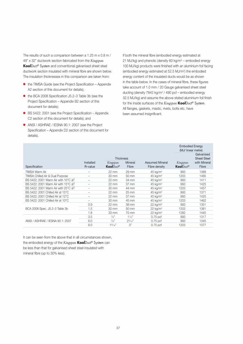
The results of such a comparison between a 1.25 m x 0.8 m /49” x 32” ductwork section fabricated from the KingspanKoolDuct® System and conventional galvanised sheet steelductwork section insulated with mineral fibre are shown below.The insulation thicknesses in this comparison are taken from:
� the TIMSA Guide (see the Project Specification – AppendixA2 section of this document for details);
� the BCA 2008 Specification J5.2–3 Table 3b (see theProject Specification – Appendix B2 section of thisdocument for details);
� BS 5422: 2001 (see the Project Specification – AppendixC2 section of this document for details); and
� ANSI / ASHRAE / IESNA 90.1: 2007 (see the ProjectSpecification – Appendix D2 section of this document fordetails).
If both the mineral fibre (embodied energy estimated at21 MJ/kg) and phenolic (density 60 kg/m3 – embodied energy100 MJ/kg) products were finished with an aluminium foil facing(embodied energy estimated at 52.5 MJ/m2) the embodiedenergy content of the insulated ducts would be as shownin the table below. In the cases of mineral fibre, these figurestake account of 1.0 mm / 20 Gauge galvanised sheet steelducting (density 7842 kg/m3 / 490 pcf – embodied energy32.5 MJ/kg) and assume the above-stated aluminium foil finishfor the inside surfaces of the Kingspan KoolDuct® System.All flanges, gaskets, mastic, rivets, bolts etc. havebeen assumed insignificant.
It can be seen from the above that in all circumstances shown,the embodied energy of the Kingspan KoolDuct® System canbe less than that for galvanised sheet steel insulated withmineral fibre (up to 30% less).
37
Embodied Energy(MJ/ linear metre)
GalvanisedThickness Sheet Steel
Installed Kingspan Mineral Assumed Mineral Kingspan with MineralSpecification R–value KoolDuct® Fibre Fibre density KoolDuct® Fibre
TIMSA Warm Air – 22 mm 29 mm 45 kg/m3 993 1389TIMSA Chilled Air & Dual Purpose – 30 mm 50 mm 45 kg/m3 1203 1485BS 5422: 2001 Warm Air with 10°C ∆T – 22 mm 34 mm 45 kg/m3 993 1411BS 5422: 2001 Warm Air with 15°C ∆T – 22 mm 37 mm 45 kg/m3 993 1425BS 5422: 2001 Warm Air with 25°C ∆T – 30 mm 44 mm 45 kg/m3 1203 1457BS 5422: 2001 Chilled Air at 15°C – 22 mm 25 mm 45 kg/m3 993 1371BS 5422: 2001 Chilled Air at 12°C – 22 mm 37 mm 45 kg/m3 993 1425BS 5422: 2001 Chilled Air at 10°C – 30 mm 45 mm 45 kg/m3 1203 1462
0.9 22 mm 38 mm 22 kg/m3 993 1351BCA 2008 Spec. J5.2–3 Table 3b 1.5 30 mm 50 mm 22 kg/m3 1203 1381
1.8 33 mm 75 mm 22 kg/m3 1282 14453.5 7/8” 11/2” 0.75 pcf 993 1317
ANSI / ASHRAE / IESNA 90.1: 2007 6.0 7/8” 23/16” 0.75 pcf 993 13458.0 13/16” 3” 0.75 pcf 1203 1377
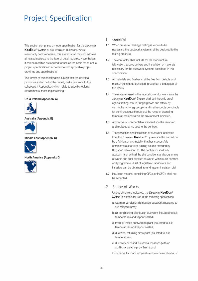
1 General1.1 When pressure / leakage testing is known to be
necessary, the ductwork system shall be designed to thetesting pressure.
1.2 The contractor shall include for the manufacture,fabrication, supply, delivery and installation of materialsnecessary for the ductwork systems described in thisspecification.
1.3 All materials and finishes shall be free from defects andmaintained in good condition throughout the duration ofthe works.
1.4 The materials used in the fabrication of ductwork from theKingspan KoolDuct® System shall be inherently proofagainst rotting, mould, fungal growth and attack byvermin, be non–hygroscopic and in all respects be suitablefor continuous use throughout the range of operatingtemperatures and within the environment indicated.
1.5 Any works of unacceptable standard shall be removedand replaced at no cost to the contract.
1.6 The fabrication and installation of ductwork fabricatedfrom the Kingspan KoolDuct® System shall be carried outby a fabricator and installer that has successfullycompleted a specialist training course provided byKingspan Insulation Ltd. The contractor shall fullyacquaint itself with all the site conditions and programmeof works and shall execute its works within such confinesand programme. A list of registered fabricators andinstallers can be obtained from Kingspan Insulation Ltd.
1.7 Insulation material containing CFC’s or HCFC’s shall notbe accepted.
2 Scope of WorksUnless otherwise indicated, the Kingspan KoolDuct®
System is suitable for use in the following applications:
a. warm air ventilation distribution ductwork (insulated tosuit temperatures);
b. air conditioning distribution ductwork (insulated to suittemperatures and vapour sealed);
c. fresh air intake ductwork to plant (insulated to suittemperatures and vapour sealed);
d. ductwork returning air to plant (insulated to suittemperatures);
e. ductwork exposed in external locations (with anadditional weatherproof finish); and
f. ductwork for room temperature non–chemical exhaust.
38
This section comprises a model specification for the KingspanKoolDuct® System of pre–insulated ductwork. Whilstreasonably comprehensive, this specification may not addressall related subjects to the level of detail required. Nevertheless,it can be modified as required for use as the basis for an actualproject specification in accordance with applicable projectdrawings and specifications.
The format of this specification is such that the universalprovisions as laid out at the outset, make reference to thesubsequent Appendices which relate to specific regionalrequirements, these regions being:
UK & Ireland (Appendix A)
Australia (Appendix B)
Middle East (Appendix C)
North America (Appendix D)
Project Specification
3 Materials3.1 The panels used in the fabrication of ductwork from the
Kingspan KoolDuct® System shall be KingspanKoolDuct® rigid phenolic insulation panels of nominaldimensions 2950 mm x 1200 mm / 9.68 ft x 3.94 ft or3930 mm x 1200 mm / 12.89 ft x 3.94 ft and minimumcompressive strength 200 kPa / 29 psi, as manufacturedby Kingspan Insulation Ltd and detailed in App. A1 / B1 /C1 / D1 (delete as applicable) of this specification.
3.2 Kingspan KoolDuct® rigid phenolic insulation panels shallcomprise a 55–60 kg/m3 / 3.4–3.75 pcf nominal densityCFC/HCFC–free rigid phenolic insulation core with zeroOzone Depletion Potential (ODP), autohesively bonded onboth sides to a 25 micron / 1 mil low vapour permeabilityaluminium foil facing reinforced with a 5 mm / 0.2” glassscrim.
3.3 Kingspan KoolDuct® rigid phenolic insulation panels areavailable in thicknesses of 22 mm / 7/8”, 30 mm 13/16” and33 mm / 15/16”. For determination of the thicknessrequired to achieve a specified thermal performance referto App. A2 / B2 / C2 / D2 (delete as applicable) of thisspecification.
3.4 All other components required for the fabrication ofductwork from the Kingspan KoolDuct® System includingthe silicone sealant, contact adhesive, aluminium tape,self–adhesive gasket, ductwork reinforcements, closures,connectors and flanges shall be as approved / suppliedby Kingspan Insulation Ltd.
4 Fire & Smoke Performance4.1 The rigid phenolic insulation panels used in the fabrication
of ductwork and / or ductwork sections fabricated fromthe Kingspan KoolDuct® System shall achieve the fire andsmoke performance requirements as detailed in App. A3 /B3 / C3/ D3 (delete as applicable) of this specification.
Fabrication of Ductwork4.2 All ductwork fabricated from the Kingspan KoolDuct®
System shall be fabricated in accordance with methods asapproved Kingspan Insulation Ltd.
4.3 Ductwork sections fabricated from the KingspanKoolDuct® System shall not exceed permitted air leakagelimits as detailed in App. A4 / B4 / C4 / D4 (delete asapplicable) of this specification.
4.4 All internal seams must be fully sealed with an unbrokenlayer of silicone sealant.
4.5 Each ductwork section must be duly connected with ajointing system approved Kingspan Insulation Ltd., andsufficient silicone sealant should be applied in order toseal the rigid phenolic insulation panel and ensureminimum air leakage.
4.6 Ductwork reinforcement, if necessary, shall be applied toprotect against side deformation from both positive andnegative pressure.
4.7 All external seams where two separate panels join mustbe taped to achieve a permanent bond and a smoothwrinkle free appearance.
4.8 The design of ductwork fittings shall be in conformancewith the appropriate ductwork construction standard asdetailed in App. A5 / B5 / C5 / D5 (delete as applicable)of this specification.
4.9 Access doors shall be provided where shown on thedrawings. These may be fabricated from the KingspanKoolDuct® System or, a commercially available pre–insulated access door may be incorporated. This accessdoor must be insulated to the same standard as theKingspan KoolDuct® rigid phenolic insulation panel andthe integrity of the vapour barrier must be maintained.
5 Storage & Handling5.1 Care shall be exercised in the handling and transportation
of ductwork sections and the Kingspan KoolDuct® rigidphenolic insulation panels from which they are fabricated,in order to prevent physical damage.
5.2 All ductwork sections, and the materials from which theyare fabricated, shall be stored under cover, clear of theground and protected from the weather and sunlight byan opaque and light coloured waterproof material. Incases where the ductwork sections are to be stored forprolonged periods, the open ends of the ductworksections shall be sealed with a polythene sheet or othersuitable material to prevent the ingress of foreign matter.
39

6 Installation of Ductwork6.1 Ductwork sections fabricated from the Kingspan
KoolDuct® System shall be installed in accordance withmethods approved by Kingspan Insulation Ltd.
6.2 The ductwork system shall be visually inspected beforecommencement of operation and ductwork sectionsfabricated from the Kingspan KoolDuct® System shall beverified as having been installed correctly.
6.3 Flexible connections shall be made between theductwork and any item which is subject to vibration ormovement.
Support6.4 It shall be the responsibility of the installer to ensure that
the ductwork system is properly and adequatelysupported. A number of support systems are approvedfor use by Kingspan Insulation Ltd. It shall be theresponsibility of the installer to ensure that the chosenmethod of support is compatible with ductworkfabricated from the Kingspan KoolDuct® System.
6.5 With the exception of Tiger Supports, all metal supportmembers in contact with the ductwork shall be separatedby a soft gasket material.
6.6 Supports on straight runs of ductwork fabricated from theKingspan KoolDuct® System shall be positioned atcentres not exceeding 3 m / 10 ft for ductwork sectionsfabricated in 3 m / 10 ft lengths, and 4 m / 13 ft forductwork sections fabricated in 4 m / 13 ft lengths.
6.7 Additionally, ductwork shall be supported at changes ofdirection, at branch duct connections, tee fittings and etc.
6.8 All ductwork accessories such as dampers shall beindependently supported.
Internal Ductwork6.9 All internal and exposed to view ductwork fabricated from
Kingspan KoolDuct® System may be provided with aprotective finish in addition to the factory appliedreinforced aluminium facing. For details, refer to App. A6 /B6 / C6 / D6 (delete as applicable) of this specification.
External Ductwork6.10 All externally mounted ductwork fabricated from the
Kingspan KoolDuct® System must be installed with aslight fall so as to shed water from its upper surface andmust be provided with a protective weatherproof finishthat shields against the effects of wind and sunlight.For details, refer to App. A6 / B6 / C6 / D6 (delete asapplicable) of this specification.
40
High Humidity Conditions6.11 High humidity conditions may increase the risk of
condensation forming on ductwork section jointingflanges. To combat this:
� all flanges can be insulated to the same thickness asthe ductwork insulation and fully vapour sealed; or
� a tropical plastic flange can be used to replace theinternal half of the aluminium grip flange, if specified.
In some high humidity conditions, a bloom may form onthe surface of the ductwork. If this is likely to be visible,the ductwork can be painted with a suitable paint finishwhich does not compromise the factory appliedreinforced aluminium facing or fire classification.
7 Testing for Air LeakageDuctwork air leakage testing shall be conducted inconformance with the procedures as set out in theappropriate standard as detailed in App. A7 / B7 / C7 /D7 (delete as applicable) of this specification.
8 Commissioning & Operating Pressures8.1 The commissioning process shall include for the testing
and verification of functional performance, preparation ofdocumentation, training of personnel for continued properoperation and maintenance of the ductwork system, andcompilation of the final commissioning report.
8.2 The commissioning pressure shall not exceed thedesigned pressure limit when a ductwork systemfabricated from the Kingspan KoolDuct® System isbeing commissioned.
9 Standards / ReferencesApp. A8 / B8 / C8 / D8 (delete as applicable)
Project Specification
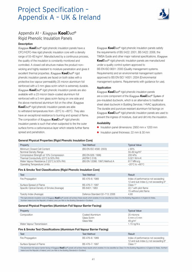
41
Appendix A1 – Kingspan KoolDuct®Rigid Phenolic Insulation PanelsDescriptionKingspan KoolDuct® rigid phenolic insulation panels have aCFC/HCFC–free rigid phenolic insulation core with a densityrange of 55–60 kg/m3. Manufactured by a continuous process,the quality of the insulation is constantly monitored andcontrolled. A closed cell structure makes the product non–wicking and highly resistant to moisture penetration and gives itexcellent thermal properties. Kingspan KoolDuct® rigidphenolic insulation panels are faced on both sides with aprotective low vapour permeability 25 micron aluminium foilreinforced with a 5 mm glass scrim which is extremely durable.Kingspan KoolDuct® rigid phenolic insulation panels are alsoavailable with a 23 micron black–coated aluminium foilreinforced with a 5 mm glass scrim facing on one side andthe above mentioned aluminium foil on the other. KingspanKoolDuct® rigid phenolic insulation panels are ableto withstand temperatures from –20°C to +80°C. They alsohave an exceptional resistance to burning and spread of flame.The composition of Kingspan KoolDuct® rigid phenolicinsulation panels is such that when subjected to fire the outersurface forms a carbonaceous layer which retards further flamespread and penetration.
Kingspan KoolDuct® rigid phenolic insulation panels satisfythe requirements of BS 5422: 2001, BS 5422: 2008, theTIMSA Guide and other major national specifications. KingspanKoolDuct® rigid phenolic insulation panels are manufacturedunder a quality control system approved toBS EN ISO 9001: 2000 (Quality management systems.Requirements) and an environmental management systemapproved to BS EN ISO 14001: 2004 (Environmentalmanagement systems. Requirements with guidance for use).
ApplicationKingspan KoolDuct® rigid phenolic insulation panelsare a core component of the Kingspan KoolDuct® System ofpre–insulated ductwork, which is an alternative to traditionalsheet steel ductwork in Building Services / HVAC applications.The durable and puncture resistant aluminium foil facings onKingspan KoolDuct® rigid phenolic insulation panels are used toprevent the ingress of moisture, dust and dirt into the insulation.
Availability� Insulation panel dimensions: 2950 mm x 1200 mm
� Insulation panel thickness: 22 mm & 30 mm
General Physical Properties (Rigid Phenolic Insulation Core)
Property Test Method Typical Value
Minimum Closed Cell Content (BS EN ISO 4590: 2003) ≥ 90%Nominal Density Range 55–60 kg/m3
Compressive Strength at 10% Compression (BS EN 826: 1996) 200 kPaThermal Conductivity (22°C & 50% RH) (ASTM C 518) 0.021 W/m.KWater Vapour Resistance Z (23°C & 50% RH) (BS EN 12086: 1997) Method A 617 MN.s/gOperating Temperature Limits –20°C to +80°C
Fire & Smoke Test Classifications (Rigid Phenolic Insulation Core)
Test Test Method Result
Fire Propagation BS 476–6: 1989 Index of performance not exceeding12 and sub index (i1) not exceeding 6*
Surface Spread of Flame BS 476–7: 1997 Class 1*Specific Optical Density of Smoke (Average) BS 6401: 1983 22.7 with pilot flame
15 without pilot flameToxicity Index (Average) Defence Standard 02–713: 2006 4.93*The rigid phenolic insulation core of Kingspan KoolDuct® panels will achieve these results which enables it to be classified as Class 0 to the Building Regulations in England & Wales,Northern Ireland and the Republic of Ireland, and Low Risk to the Building Standards in Scotland.
General Physical Properties (Aluminium Foil Vapour Barrier Facing)
Property Typical Value
Composition Coated Aluminium 25 micronsGlass Scrim 5 mm x 5 mmGlass Mat 49 g/m2
Water Vapour Transmission 1.15 ng.N.s
Fire & Smoke Test Classifications (Aluminium Foil Vapour Barrier Facing)
Test Test Method Result
Fire Propagation BS 476–6: 1989 Index of performance not exceeding12 and sub index (i1) not exceeding 6*
Surface Spread of Flame BS 476–7: 1997 Class 1**The aluminium foil vapour barrier facing of Kingspan KoolDuct® panels will achieve these results which enables it to be classified as Class 0 to the Building Regulations in England & Wales, NorthernIreland and the Republic of Ireland, and Low Risk to the Building Standards in Scotland.
Project Specification –Appendix A – UK & Ireland
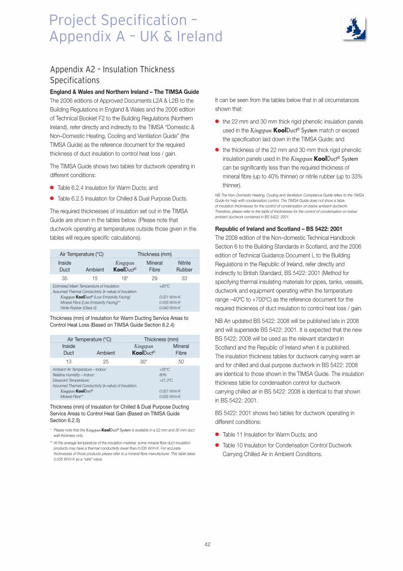
42
Appendix A2 – Insulation ThicknessSpecificationsEngland & Wales and Northern Ireland – The TIMSA GuideThe 2006 editions of Approved Documents L2A & L2B to theBuilding Regulations in England & Wales and the 2006 editionof Technical Booklet F2 to the Building Regulations (NorthernIreland), refer directly and indirectly to the TIMSA “Domestic &Non–Domestic Heating, Cooling and Ventilation Guide” (theTIMSA Guide) as the reference document for the requiredthickness of duct insulation to control heat loss / gain.
The TIMSA Guide shows two tables for ductwork operating indifferent conditions:
� Table 6.2.4 Insulation for Warm Ducts; and
� Table 6.2.5 Insulation for Chilled & Dual Purpose Ducts.
The required thicknesses of insulation set out in the TIMSAGuide are shown in the tables below. (Please note thatductwork operating at temperatures outside those given in thetables will require specific calculations).
It can be seen from the tables below that in all circumstancesshown that:
� the 22 mm and 30 mm thick rigid phenolic insulation panelsused in the Kingspan KoolDuct® System match or exceedthe specification laid down in the TIMSA Guide; and
� the thickness of the 22 mm and 30 mm thick rigid phenolicinsulation panels used in the Kingspan KoolDuct® Systemcan be significantly less than the required thickness ofmineral fibre (up to 40% thinner) or nitrile rubber (up to 33%thinner).
NB The Non–Domestic Heating, Cooling and Ventilation Compliance Guide refers to the TIMSAGuide for help with condensation control. The TIMSA Guide does not show a tableof insulation thicknesses for the control of condensation on below ambient ductwork.Therefore, please refer to the table of thicknesses for the control of condensation on belowambient ductwork contained in BS 5422: 2001.
Republic of Ireland and Scotland – BS 5422: 2001The 2008 edition of the Non–domestic Technical HandbookSection 6 to the Building Standards in Scotland, and the 2006edition of Technical Guidance Document L to the BuildingRegulations in the Republic of Ireland, refer directly andindirectly to British Standard, BS 5422: 2001 (Method forspecifying thermal insulating materials for pipes, tanks, vessels,ductwork and equipment operating within the temperaturerange –40ºC to +700ºC) as the reference document for therequired thickness of duct insulation to control heat loss / gain.
NB An updated BS 5422: 2008 will be published late in 2008and will supersede BS 5422: 2001. It is expected that the newBS 5422: 2008 will be used as the relevant standard inScotland and the Republic of Ireland when it is published.The insulation thickness tables for ductwork carrying warm airand for chilled and dual purpose ductwork in BS 5422: 2008are identical to those shown in the TIMSA Guide. The insulationthickness table for condensation control for ductworkcarrying chilled air in BS 5422: 2008 is identical to that shownin BS 5422: 2001.
BS 5422: 2001 shows two tables for ductwork operating indifferent conditions:
� Table 11 Insulation for Warm Ducts; and
� Table 10 Insulation for Condensation Control DuctworkCarrying Chilled Air in Ambient Conditions.
Air Temperature (°C) Thickness (mm)
Inside Kingspan Mineral NitrileDuct Ambient KoolDuct® Fibre Rubber
35 15 18* 29 33Estimated Mean Temperature of Insulation: +20°CAssumed Thermal Conductivity (k–value) of Insulation:
Kingspan KoolDuct® (Low Emissivity Facing) 0.021 W/m.KMineral Fibre (Low Emissivity Facing)** 0.035 W/m.KNitrile Rubber (Class 0) 0.040 W/m.K
Thickness (mm) of Insulation for Warm Ducting Service Areas toControl Heat Loss (Based on TIMSA Guide Section 6.2.4)
Air Temperature (°C) Thickness (mm)Inside Kingspan MineralDuct Ambient KoolDuct® Fibre
13 25 30* 50Ambient Air Temperature – Indoor: +25°CRelative Humidity – Indoor: 80%Dewpoint Temperature: +21.3°CAssumed Thermal Conductivity (k–value) of Insulation:
Kingspan KoolDuct® 0.021 W/m.KMineral Fibre** 0.035 W/m.K
Thickness (mm) of Insulation for Chilled & Dual Purpose DuctingService Areas to Control Heat Gain (Based on TIMSA GuideSection 6.2.5)
* Please note that the Kingspan KoolDuct® System is available in a 22 mm and 30 mm ductwall thickness only.
** At the average temperature of the insulation material, some mineral fibre duct insulationproducts may have a thermal conductivity lower than 0.035 W/m.K. For accuratethicknesses of those products please refer to a mineral fibre manufacturer. This table takes0.035 W/m.K as a “safe” value.
Project Specification –Appendix A – UK & Ireland

43
The required thicknesses of insulation set out in BS 5422: 2001are shown in the tables below. (Please note that ductworkoperating at temperatures outside those given in the tables willrequire specific calculations).
Temperaturedifference
between air inside Thickness (mm)ductwork and Kingspan Mineral Nitrileambient air (˚C) KoolDuct® Fibre Rubber
10 20* 34 38
15 22* 37 42
25 27* 44 50Estimated Mean Temperature of Insulation: +20°CAssumed Thermal Conductivity (k–value) of Insulation:
Kingspan KoolDuct® 0.021 W/m.KMineral Fibre** 0.035 W/m.KNitrile Rubber (Class 0) 0.040 W/m.K
Environmental Thickness (mm) of Insulation for Ductwork CarryingWarm Air to Control Heat Loss (Based on BS 5422: 2001 Table 11)
Minimum air Thickness (mm)temperature Kingspan Mineral
inside ductwork (˚C) KoolDuct® Fibre
15 16* 25
12 22* 37
10 28* 45Ambient Air Temperature – Indoor: +25°CRelative Humidity – Indoor: 80%Dewpoint Temperature: +21.3°CAssumed Thermal Conductivity (k–value) of Insulation:
Kingspan KoolDuct® 0.021 W/m.KMineral Fibre** 0.035 W/m.K
Thickness (mm) of Insulation for Condensation Control DuctworkCarrying Chilled Air in Ambient Conditions (Based onBS 5422: 2001 Table 10)
* Please note that the Kingspan KoolDuct® System is available in a 22mm and 30 mm ductwall thickness only.
** At the average temperature of the insulation material, some mineral fibre duct insulationproducts may have a thermal conductivity lower than 0.035 W/m.K. For accuratethicknesses of those products please refer to a mineral fibre manufacturer. This table takes0.035 W/m.K as a “safe” value.
It can be seen from the tables that in all circumstancesshown that:
� the 22 mm and 30 mm thick rigid phenolic insulation panelsused in the Kingspan KoolDuct® System match or exceedthe specification laid down in BS 5422: 2001; and
� the thickness of the 22 mm and 30 mm thick rigidphenolic insulation panels used in the Kingspan KoolDuct®
System can be significantly less than the required thicknessof mineral fibre (up to 40% thinner) or nitrile rubber (up to47% thinner).
Appendix A3 – Fire & Smoke PerformanceThe appropriate fire and smoke performance requirements forthe UK & Ireland are detailed below.
Internal Ductwork� BS 476–6: 1989 – of low contribution to fire growth with fire
propagation index of performance (I) not exceeding 12 andsub index (i1) not exceeding 6;
� BS 476–7: 1997 – of very low surface spread of flame(Class 1); and
� Class 0 / Low Risk to the Building Regulations / Standards.
External Ductwork� BS 476–7: 1997 – of very low surface spread of flame
(Class 1).
Appendix A4 – Air Leakage LimitsHVCA DW/144 details the maximum allowable air leakage asshown in the table below:
Static Pressure Maximum Air LeakageDuct Pressure Limit (Pa) Air Velocity LimitsClass Positive Negative (m/s) (l/s/m2)
Low–Pressure(Class A) 500 500 10 0.027 x p0.65
Medium–Pressure(Class B) 1000 750 20 0.009 x p0.65
High–Pressure(Class C) 2000 750 40 0.003 x p0.65
p = static pressure differential (Pa)
Based on the limits set out in table above, the maximumallowable air leakage for each pressure class over a rangeof pressures from 0 to 2,000 Pascals (Pa) is plotted in thegraph below. The leakage figures are given in litres of air persecond per square metre (l/s/m2) of internally measuredductwork against a static pressure differential ranging from100 Pa to 2,000 Pa.
Appendix A5 – Ductwork FittingsThe appropriate ductwork construction standard for theUK & Ireland is HVCA DW/144 (Specification for Sheet MetalDuctwork).
Appendix A6 – FinishesInternal DuctworkThe finish shall be either:
a) aluminium / zinc alloy coated sheet steel (0.7 mm) (e.g.Dobel Aluzinc or equivalent) which can be introduced duringfabrication of the ductwork or installed in situ; or
b) a suitable paint finish (must not compromise factoryapplied reinforced aluminium facing or fire classification)applied in situ.
External DuctworkThe finish shall be either:
a) an aluminium cladding / jacketing system (e.g. Venture Clador equivalent) which can be introduced during fabrication ofthe ductwork or installed in situ;
b) aluminium / zinc alloy coated sheet steel (0.8 mm) (e.g.Dobel Aluzinc or equivalent) which can be introduced duringfabrication of the ducting or installed in situ;
c) a fibre reinforced plastic (e.g. Fibaroll GR Grade orequivalent) which is introduced during the fabrication ofthe ductwork; or
d) a polymeric weather covering (for sheltered locations)installed in situ.
Manufacturers of FinishesFor Dobel Aluzinc aluminium zinc alloy coated sheet steelrefer to:SSAB Dobel Coated Steel LtdNarrowboat WayHurst Business ParkBrierley HillWest MidlandsDY5 1UFTel: +44 (0) 1384 74 660Fax: +44 (0) 1384 77 575www.dobel.co.uk
For Venture Clad aluminium jacketing system refer to:Venture Tape Europe Corp.Units 5–6Faraday CloseDrayton FieldsDaventryNorthamptonshireNN11 8RDTel: +44 (0) 1327 876 555Fax: +44 (0) 1327 876 444www.venturetape.com
For Fibaroll FR Grade fibre reinforced plastic coating forinsulation refer to:FTi LtdWillmotts Business ParkWaterlipSomersetBA4 4RNTel: +44 (0) 1749 881 920Fax: +44 (0) 1749 880 843www.fibaroll.co.uk
Appendix A7 – Testing for Air LeakageApproved Documents L2A & L2B to the Building Regulations inEngland & Wales, and Technical Booklet F2 to the BuildingRegulations (Northern Ireland), state that ductwork leakagetesting should be carried out in accordance with theprocedures set out in HVCA DW/143 on systems served byfans with a design flow rate greater than 1 m3/s, and for thosesections of ductwork where the pressure class is such thatHVCA DW/143 recommends testing and the carbon dioxideemissions rate of the building design assumes a leakage ratefor a given section of ductwork that is lower than the standarddefined in HVCA DW/144 for its particular pressure class.Technical Handbook Section 6 to the Building Standards inScotland state that one way of carrying out ductwork leakagetesting is to follow the procedures set out in HVCA DW/143.
HVCA DW/143 (A Practical Guide to Ductwork LeakageTesting) recommends the range and frequency of testing thatit deems to be satisfactory.
It recommends the following:
� high pressure ducts (Class C) – all tested;
� medium pressure ducts (Class B) – 10% of the ductworkselected at random and tested; and
� low pressure ducts (Class A) – untested.
It is also recommended:
� for medium pressure ducts, in the event of test failure of therandomly selected section, the designer shall have the rightto select two further sections at random for testing. Wheresuccessive failures are identified there shall be a right torequire the contractor to apply remedial attention to thecomplete ductwork system; and
� in general for all ducts tested, that the air leakage rate for anysection shall not be in excess of the permitted rate (as statedin HVCA DW/144) for that section. If a first test producesleakage in excess of the permitted maximum, the sectionshall be resealed and retested until a leakage not greaterthan the permitted maximum for that section is achieved.
44
Project Specification –Appendix A – UK & Ireland
45
Appendix A8– Standards / ReferencesBritish StandardsBS 476–6: 1989Fire tests on building materials and structures. Method of testfor fire propagation for products
BS 476–7: 1997Fire tests on building materials and structures. Method of testto determine the classification of the surface spread of flameof products
BS 6401: 1983Method for measurement, in the laboratory, of the specificoptical density of smoke generated by materials.
BS 5422: 2001Method for specifying thermal insulating materials for pipes,tanks, vessels, ductwork and equipment operating within thetemperature range –40ºC to +700ºC
BS 5422: 2008Method for specifying thermal insulating materials for pipes,tanks, vessels, ductwork and equipment operating within thetemperature range –40ºC to +700ºC
BS EN 826:1996Thermal insulating products for building applications.Determination of compression behaviour
BS EN 12086:1997Thermal insulating products for building applications.Determination of water vapour transmission properties
BS EN ISO 4590: 2003Rigid cellular plastics. Determination of the volume percentageof open cells and of closed cells
BS EN ISO 9001: 2000Quality management systems. Requirements
BS EN ISO 14001: 2004Environmental management systems. Requirements withguidance for use)
American StandardsASTM C 518: 2004Standard Test Method for Steady–State Thermal TransmissionProperties by Means of the Heat Flow Meter Apparatus
Other ReferencesTIMSA GuideTIMSA Domestic & Non–Domestic Heating, Cooling andVentilation Guide
HVCA DW/144Specification for Sheet Metal Ductwork
HVCA DW/143A practical guide to Ductwork Leakage Testing
Defence Standard 02–713: 2006Determination of the Toxicity Index of the Products ofCombustion from Small Specimens of Material
Building Regulations / StandardsEngland & WalesThe Building Regulations 2000. Approved Document B2. 2006Edition, Amended 2007. Appendix A, Paragraph 13.
The Building Regulations 2000. Approved Document L2A.2006 Edition.
The Building Regulations 2000. Approved Document L2B.2006 Edition.
ScotlandThe Building Standards (Scotland) Regulations. Non–domesticTechnical Handbook Section 2 (Fire). 2008 Edition. Annex 2C.
The Building Standards (Scotland) Regulations. Non–domesticTechnical Handbook Section 6 (Energy). 2008 Edition.
Northern IrelandThe Building Regulations (Northern Ireland) 2000. TechnicalBooklet E. 2005 Edition. Paragraph 2.4
The Building Regulations (Northern Ireland) 2000. TechnicalBooklet F2. 2006 Edition.
Irish RepublicThe Building Regulations 2006. Technical Guidance DocumentB. Appendix A. Paragraphs A11 and A12
The Building Regulations 2005. Technical Guidance DocumentL. May 2006 Edition.
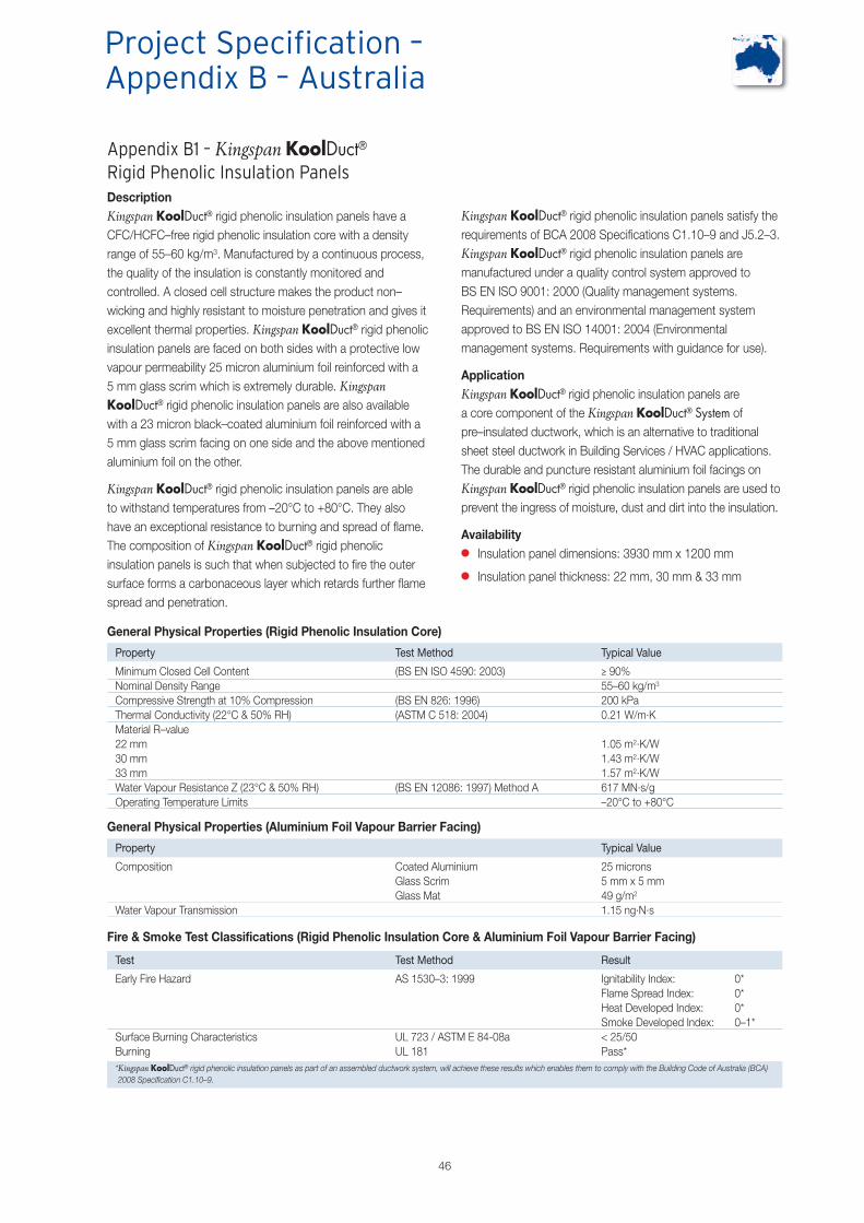
46
Kingspan KoolDuct® rigid phenolic insulation panels satisfy therequirements of BCA 2008 Specifications C1.10–9 and J5.2–3.Kingspan KoolDuct® rigid phenolic insulation panels aremanufactured under a quality control system approved toBS EN ISO 9001: 2000 (Quality management systems.Requirements) and an environmental management systemapproved to BS EN ISO 14001: 2004 (Environmentalmanagement systems. Requirements with guidance for use).
ApplicationKingspan KoolDuct® rigid phenolic insulation panels area core component of the Kingspan KoolDuct® System ofpre–insulated ductwork, which is an alternative to traditionalsheet steel ductwork in Building Services / HVAC applications.The durable and puncture resistant aluminium foil facings onKingspan KoolDuct® rigid phenolic insulation panels are used toprevent the ingress of moisture, dust and dirt into the insulation.
Availability� Insulation panel dimensions: 3930 mm x 1200 mm
� Insulation panel thickness: 22 mm, 30 mm & 33 mm
Appendix B1 – Kingspan KoolDuct®Rigid Phenolic Insulation PanelsDescriptionKingspan KoolDuct® rigid phenolic insulation panels have aCFC/HCFC–free rigid phenolic insulation core with a densityrange of 55–60 kg/m3. Manufactured by a continuous process,the quality of the insulation is constantly monitored andcontrolled. A closed cell structure makes the product non–wicking and highly resistant to moisture penetration and gives itexcellent thermal properties. Kingspan KoolDuct® rigid phenolicinsulation panels are faced on both sides with a protective lowvapour permeability 25 micron aluminium foil reinforced with a5 mm glass scrim which is extremely durable. KingspanKoolDuct® rigid phenolic insulation panels are also availablewith a 23 micron black–coated aluminium foil reinforced with a5 mm glass scrim facing on one side and the above mentionedaluminium foil on the other.
Kingspan KoolDuct® rigid phenolic insulation panels are ableto withstand temperatures from –20°C to +80°C. They alsohave an exceptional resistance to burning and spread of flame.The composition of Kingspan KoolDuct® rigid phenolicinsulation panels is such that when subjected to fire the outersurface forms a carbonaceous layer which retards further flamespread and penetration.
Project Specification –Appendix B – Australia
General Physical Properties (Rigid Phenolic Insulation Core)
Property Test Method Typical Value
Minimum Closed Cell Content (BS EN ISO 4590: 2003) ≥ 90%Nominal Density Range 55–60 kg/m3
Compressive Strength at 10% Compression (BS EN 826: 1996) 200 kPaThermal Conductivity (22°C & 50% RH) (ASTM C 518: 2004) 0.21 W/m.KMaterial R–value22 mm 1.05 m2.K/W30 mm 1.43 m2.K/W33 mm 1.57 m2.K/WWater Vapour Resistance Z (23°C & 50% RH) (BS EN 12086: 1997) Method A 617 MN.s/gOperating Temperature Limits –20°C to +80°C
General Physical Properties (Aluminium Foil Vapour Barrier Facing)
Property Typical Value
Composition Coated Aluminium 25 micronsGlass Scrim 5 mm x 5 mmGlass Mat 49 g/m2
Water Vapour Transmission 1.15 ng.N.s
Fire & Smoke Test Classifications (Rigid Phenolic Insulation Core & Aluminium Foil Vapour Barrier Facing)
Test Test Method Result
Early Fire Hazard AS 1530–3: 1999 Ignitability Index: 0*Flame Spread Index: 0*Heat Developed Index: 0*Smoke Developed Index: 0–1*
Surface Burning Characteristics UL 723 / ASTM E 84-08a < 25/50Burning UL 181 Pass**Kingspan KoolDuct® rigid phenolic insulation panels as part of an assembled ductwork system, will achieve these results which enables them to comply with the Building Code of Australia (BCA)2008 Specification C1.10–9.

47
Appendix B2 – Insulation ThicknessSpecificationsBuilding Code of Australia (BCA) 2008The Energy Efficiency Provisions of BCA 2008 specify theminimum required thermal performance standards for ductworkinsulation, meeting the requirements of AS NZS 4859–1: 2002,installed on air conditioning ductwork in Class 5 to 9 buildings.
BCA 2008 Specification J5.2–3 shows two tables with theminimum required total R–value for ductwork operating indifferent climate zones and locations:
� Table 3a Combined Heating and Cooling Ductwork Systemsgreater than 65k Wr & 65 kWheating Capacity; and
� Table 3b Heating / Cooling Only Ductwork & Fittings forDuctwork Systems less than 65k Wr & 65 kWheating Capacity
The different climate zones are shown on the map to the right.
BCA 2008 Climate Zone Map for Australian Locations
Total Thermal Resistance (Rt) of Ductwork Fabricated From the Kingspan KoolDuct® System Including the Effect ofLow Emissivity Facings
Panel Thickness (mm) Application Ambient Conditions Calculated Rt (m2.K/W)
22
Cooling Application1 Ambient Air Flowing at 0.5 m/s 1.18Still Ambient Air 1.52
Heating Application2 Ambient Air Flowing at 0.5 m/s 1.15Still Ambient Air 1.47
30
Cooling Application1 Ambient Air Flowing at 0.5 m/s 1.57Still Ambient Air 1.91
Heating Application2 Ambient Air Flowing at 0.5 m/s 1.53Still Ambient Air 1.85
33
Cooling Application1 Ambient Air Flowing at 0.5 m/s 1.72
Still Ambient Air 2.06
Heating Application2Ambient Air Flowing at 0.5 m/s 1.67
Still Ambient Air 1.991 Calculated using 13ºC supply air and 26ºC ambient environment.2 Calculated using 30ºC supply air and 18ºC ambient environment.Rt determinations based upon AS / NZS 4859: 2002.Assumed Thermal Conductivity (k–value) of insulation at 23°C mean temp: 0.021 W/m.K.

48
Appendix B2 – Insulation ThicknessSpecifications (Continued)The Kingspan KoolDuct® rigid phenolic insulation panelthickness required to achieve the specified thermalperformance standards as set out in the BCA 2008Specification J5.2–3 tables are shown below.
NB that, in some climates, the minimum energy efficiency requirements may not be sufficientfor condensation control. In such cases, the risk of condensation should be assessed andcalculated as appropriate.
Different Duct Insulation Thicknesses (mm) for the Minimum Required R–values for Ductwork in Each Climate ZoneEvaporative
Cooling System Heating / Refrigerated Cooling Only System Combined Heating & Refrigerated Cooling SystemDuctwork All Zones Zones Zone Zones Zones ZoneElement Zones 1,3,4,6 & 7 2 & 5 8 1,3,4,6 & 7 2 & 5 8
R–0.6 R–1.0 R–1.0 R–1.5 R–1.5* R–1.0 R–1.5Ductwork 22 / 25 22 / 38 22 / 38 30 / 50 30 / 50 22 / 38 30 / 50
R–0.4 R–0.4 R–0.4 R–0.4 R–0.4 R–0.4 R–0.4Fittings 22 / 25 22 / 25 22 / 25 22 / 25 22 / 25 22 / 25 22 / 25*The minimum total R–value required may be reduced by R–0.5 for combined heating refrigerated cooling systems in climate zones 1,3, 4, 6 & 7 if the ductwork is located:(a) under a suspended floor with an enclosed perimeter; or(b) in a roof space that has insulation of not less than R–0.5 directly beneath the roofing.Blue: Kingspan KoolDuct®: Assumed R–value : 22 mm (R–1.05); 30 mm (R–1.43); 33 mm (R–1.57).Red: Mineral Fibre: Assumed R–value: 25 mm (R–0.7); 38 mm (R–1.0); 50 mm (R–1.4); 75 mm (R–2.0).
Table B1 – Minimum Insulation Required to Achieve the Total R–values for Ductwork & Fittings in Each Climate Zone for Systems Less than65 kWr & 65 kWheating Capacity (Based on BCA 2008 Spec J5.2–3 Table 3a)
Different Duct Insulation Thicknesses (mm) for the Minimum Required R–valuesfor Ductwork in Each Climate Zone
EvaporativeCooling System Heating / Refrigerated Cooling Only System
Location of Ductwork All Zones Zones Zones Zone& Fittings Zones 1,3 & 4 2 & 5 6 &7 8
Within a conditioned space other than where Nil R–1.0 R–1.0 R–1.3 R–1.5the space is the only or last space served 22 / 38 22 / 38 30 / 50 30 / 50
All other locationsR–0.9 R–1.8* R–1.5 R–1.8 R–2.022 / 38 33 / 75 30 / 50 33 / 75 N/A / 75
*The minimum total R–value required may be reduced by R–0.5 for heating / refrigerated cooling only system ductwork and fittings in all other locations in climate zones 1,3 & 4 if the ductwork is located:(a) under a suspended floor with an enclosed perimeter; or(b) in a roof space that has insulation of not less than R–0.5 directly beneath the roofing.Blue: Kingspan KoolDuct®: Assumed R–value : 22 mm (R–1.05); 30 mm (R–1.43); 33 mm (R–1.57).Red: Mineral Fibre: Assumed R–value: 25 mm (R–0.7); 38 mm (R–1.0); 50 mm (R–1.4); 75 mm (R–2.0).
Table B2 – Minimum Insulation Required to Achieve the Total R–values for Ductwork in Each Climate Zone for Systems Greater than 65 kWr &65 kWheating Capacity (Based on BCA 2008 Spec J5.2–3 Table 3b)
It can be seen from the tables above that:
� in all circumstances shown that the 22 mm, 30 mm and33 mm thick rigid phenolic insulation panels used in theKingspan KoolDuct® System match or exceed thespecification laid down in BCA 2008; and
� the thickness of the 22 mm, 30 mm and 33 mm thick rigidphenolic insulation panels used in the Kingspan KoolDuct®
System can be significantly less than the required thicknessof mineral fibre (up to 56% thinner).
Project Specification –Appendix B – Australia
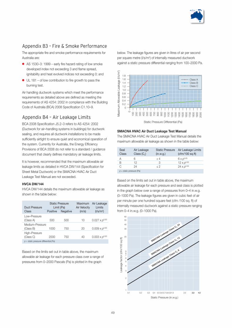
SMACNA HVAC Air Duct Leakage Test ManualThe SMACNA HVAC Air Duct Leakage Test Manual details themaximum allowable air leakage as shown in the table below:
Seal Air Leakage Static Pressure Air Leakage LimitsClass Class (CL) (in.w.g.) (cfm/100 sq.ft)
A 6 ≥ 4 6 x p0.65
B 12 3 12 x p0.65
C 24 ≤ 2 24 x p0.65
p = static pressure (Pa)
Based on the limits set out in table above, the maximumallowable air leakage for each pressure and seal class is plottedin the graph below over a range of pressures from 0–4 in.w.g.(0–1000 Pa). The leakage figures are given in cubic feet of airper minute per one hundred square feet (cfm /100 sq. ft) ofinternally measured ductwork against a static pressure rangingfrom 0–4 in.w.g. (0–1000 Pa).
49
Static Pressure Maximum Air LeakageDuct Pressure Limit (Pa) Air Velocity LimitsClass Positive Negative (m/s) (l/s/m2)
Low–Pressure(Class A) 500 500 10 0.027 x p0.65
Medium–Pressure(Class B) 1000 750 20 0.009 x p0.65
High–Pressure(Class C) 2000 750 40 0.003 x p0.65
p = static pressure differential (Pa)
below. The leakage figures are given in litres of air per secondper square metre (l/s/m2) of internally measured ductworkagainst a static pressure differential ranging from 100–2000 Pa.
Based on the limits set out in table above, the maximumallowable air leakage for each pressure class over a range ofpressures from 0–2000 Pascals (Pa) is plotted in the graph
Appendix B3 – Fire & Smoke PerformanceThe appropriate fire and smoke performance requirements forAustralia are:
� AS 1530–3: 1999 – early fire hazard rating of low smokedeveloped index not exceeding 3 and flame spread,ignitability and heat evolved indices not exceeding 0; and
� UL 181 – of low contribution to fire growth to pass theburning test.
Air handling ductwork systems which meet the performancerequirements as detailed above are defined as meeting therequirements of AS 4254: 2002 in compliance with the BuildingCode of Australia (BCA) 2008 Specification C1.10–9.
Appendix B4 – Air Leakage LimitsBCA 2008 Specification J5.2–3 refers to AS 4254: 2002(Ductwork for air–handling systems in buildings) for ductworksealing, and requires all ductwork installations to be madesufficiently airtight to ensure quiet and economical operation ofthe system. Currently for Australia, the Energy EfficiencyProvisions of BCA 2008 do not refer to a standard / guidancedocument that clearly defines mandatory air leakage limits.
It is however, recommended that the maximum allowable airleakage limits as detailed in HVCA DW/144 (Specification forSheet Metal Ductwork) or the SMACNA HVAC Air DuctLeakage Test Manual are not exceeded.
HVCA DW/144HVCA DW/144 details the maximum allowable air leakage asshown in the table below:
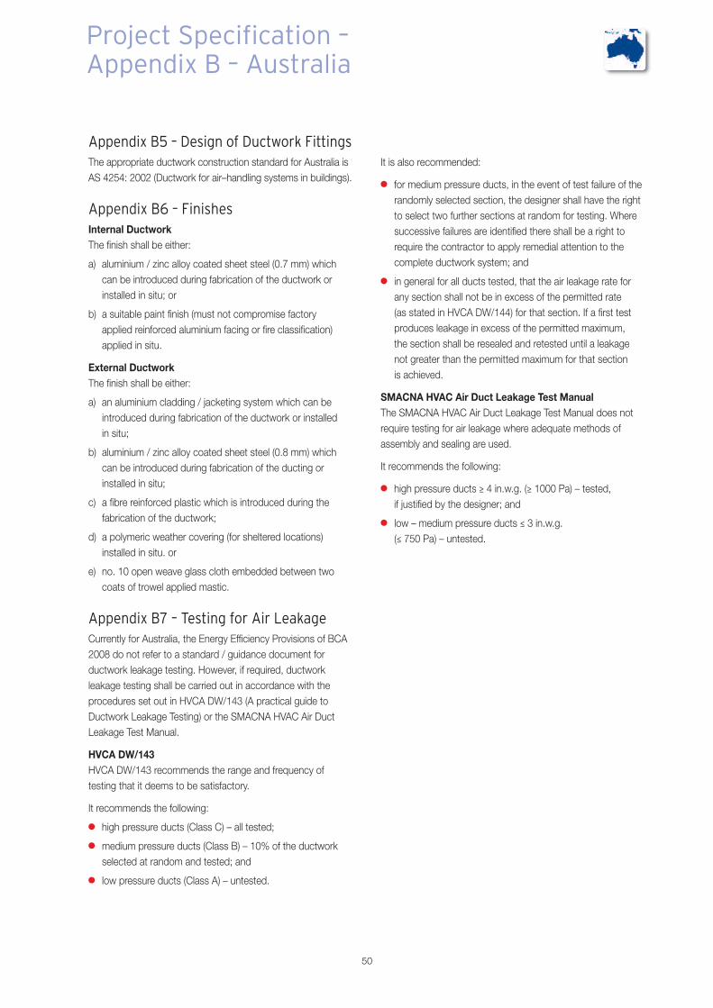
50
Appendix B5 – Design of Ductwork FittingsThe appropriate ductwork construction standard for Australia isAS 4254: 2002 (Ductwork for air–handling systems in buildings).
Appendix B6 – FinishesInternal DuctworkThe finish shall be either:
a) aluminium / zinc alloy coated sheet steel (0.7 mm) whichcan be introduced during fabrication of the ductwork orinstalled in situ; or
b) a suitable paint finish (must not compromise factoryapplied reinforced aluminium facing or fire classification)applied in situ.
External DuctworkThe finish shall be either:
a) an aluminium cladding / jacketing system which can beintroduced during fabrication of the ductwork or installedin situ;
b) aluminium / zinc alloy coated sheet steel (0.8 mm) whichcan be introduced during fabrication of the ducting orinstalled in situ;
c) a fibre reinforced plastic which is introduced during thefabrication of the ductwork;
d) a polymeric weather covering (for sheltered locations)installed in situ. or
e) no. 10 open weave glass cloth embedded between twocoats of trowel applied mastic.
Appendix B7 – Testing for Air LeakageCurrently for Australia, the Energy Efficiency Provisions of BCA2008 do not refer to a standard / guidance document forductwork leakage testing. However, if required, ductworkleakage testing shall be carried out in accordance with theprocedures set out in HVCA DW/143 (A practical guide toDuctwork Leakage Testing) or the SMACNA HVAC Air DuctLeakage Test Manual.
HVCA DW/143HVCA DW/143 recommends the range and frequency oftesting that it deems to be satisfactory.
It recommends the following:
� high pressure ducts (Class C) – all tested;
� medium pressure ducts (Class B) – 10% of the ductworkselected at random and tested; and
� low pressure ducts (Class A) – untested.
It is also recommended:
� for medium pressure ducts, in the event of test failure of therandomly selected section, the designer shall have the rightto select two further sections at random for testing. Wheresuccessive failures are identified there shall be a right torequire the contractor to apply remedial attention to thecomplete ductwork system; and
� in general for all ducts tested, that the air leakage rate forany section shall not be in excess of the permitted rate(as stated in HVCA DW/144) for that section. If a first testproduces leakage in excess of the permitted maximum,the section shall be resealed and retested until a leakagenot greater than the permitted maximum for that sectionis achieved.
SMACNA HVAC Air Duct Leakage Test ManualThe SMACNA HVAC Air Duct Leakage Test Manual does notrequire testing for air leakage where adequate methods ofassembly and sealing are used.
It recommends the following:
� high pressure ducts ≥ 4 in.w.g. (≥ 1000 Pa) – tested,if justified by the designer; and
� low – medium pressure ducts ≤ 3 in.w.g.(≤ 750 Pa) – untested.
Project Specification –Appendix B – Australia

51
Appendix B8– Standards / ReferencesAustralian / New Zealand StandardsAS / NZS 1530–3: 1999Methods for fire tests on building materials, components andstructures – Simultaneous determination of ignitability, flamepropagation, heat release and smoke release
AS / NSZ 4859–1: 2002 / Amdt 1: 2006Materials for the Thermal Insulation of Buildings – GeneralCriteria and technical provisions.
AS 4254: 2002Ductwork for air–handling systems in buildings
British StandardsBS EN 826:1996Thermal insulating products for building applications.Determination of compression behaviour
BS EN 12086:1997Thermal insulating products for building applications.Determination of water vapour transmission properties
BS EN ISO 4590: 2003Rigid cellular plastics. Determination of the volume percentageof open cells and of closed cells
BS EN ISO 9001: 2000Quality management systems. Requirements
BS EN ISO 14001: 2004Environmental management systems. Requirements withguidance for use)
American StandardsASTM C 518: 2004Standard Test Method for Steady–State Thermal TransmissionProperties by Means of the Heat Flow Meter Apparatus
Other ReferencesHVCA DW/144Specification for Sheet Metal Ductwork
HVCA DW/143A practical guide to Ductwork Leakage Testing
SMACNAHVAC Air Duct Test Leakage Manual
Building CodesBuilding Code of Australia (BCA 2008)Volume 2 Class 5 to 9 Buildings Specification C1.10–9
Building Code of Australia (BCA 2008)Volume 2 Class 5 to 9 Buildings Specification J5.2–3

52
Project Specification –Appendix C – Middle East
Appendix C1 – Kingspan KoolDuct®Rigid Phenolic Insulation PanelsDescriptionKingspan KoolDuct® rigid phenolic insulation panels have aCFC/HCFC–free rigid phenolic insulation core with a densityrange of 55–60 kg/m3 / 3.43–3.75 pcf. Manufactured by acontinuous process, the quality of the insulation is constantlymonitored and controlled. A closed cell structure makes theproduct non–wicking and highly resistant to moisturepenetration and gives it excellent thermal properties. KingspanKoolDuct® rigid phenolic insulation panels are faced on bothsides with a protective low vapour permeability 25 micron / 1mil aluminium foil reinforced with a 5 mm / 0.2” glass scrimwhich is extremely durable. Kingspan KoolDuct® rigid phenolicinsulation panels are also available with a 23 micron / 0.9 milblack–coated aluminium foil reinforced with a 5 mm / 0.2” glassscrim facing on one side and the above mentioned aluminiumfoil on the other.
Kingspan KoolDuct® rigid phenolic insulation panels are able towithstand temperatures from –20°C to +80°C / 4°F to + 176°F.They also have an exceptional resistance to burning andspread of flame. The composition of Kingspan KoolDuct® rigidphenolic insulation panels is such that when subjected to firethe outer surface forms a carbonaceous layer which retardsfurther flame spread and penetration.
Kingspan KoolDuct® rigid phenolic insulation panels satisfy therequirements of the UAE Ministry of Interior Dubai Civil Defense,BS 5422: 2001 (Method for specifying thermal insulatingmaterials for pipes, tanks, vessels, ductwork and equipmentoperating within the temperature range –40ºC to +700ºC /–40ºF to –1292ºC) and ANSI / ASHRAE / IESNA 90.1: 2007(Energy Standard for Buildings Except Low–Rise ResidentialBuildings) and other major specifications. Kingspan KoolDuct®rigid phenolic insulation panels are manufactured under aquality control system approved to BS EN ISO 9001: 2000(Quality management systems. Requirements) and anenvironmental management system approved to BS EN ISO14001: 2004 (Environmental management systems.Requirements with guidance for use).
ApplicationKingspan KoolDuct® rigid phenolic insulation panels are a corecomponent of the Kingspan KoolDuct® System of pre–insulatedductwork, which is an alternative to traditional sheet steelductwork in Building Services / HVAC applications. The durableand puncture resistant aluminium foil facings on KingspanKoolDuct® rigid phenolic insulation panels are used to preventthe ingress of moisture, dust and dirt into the insulation.
Availability� Insulation panel dimensions: 3930 mm x 1200 mm /
12.89 ft x 3.94 ft
� Insulation panel thickness: 22 mm / 7/8” &30 mm / 13/16”
General Physical Properties (Rigid Phenolic Insulation Core)Property Test Method Typical Value
Minimum Closed Cell Content (BS EN ISO 4590: 2003) ≥ 90%Nominal Density Range 55–60 kg/m3 / 3.43–3.75 pcfCompressive Strength at 10% Compression (BS EN 826: 1996) 200 kPa / 29 psiThermal Conductivity (23°C / 75°F & 50% RH) (ASTM C 518) 0.021 W/m.K / 0.146 Btu.in/ft2.hr.°FR–value:22 mm / 7/8” 1.05 m2.K/W / 6.0 ft2.hr.°F/Btu30 mm / 13/16” 1.43 m2.K/W / 8.1 ft2.hr.°F/BtuWater Vapour Transmission (23°C / 75°F & 50% RH) (ASTM E 96) 617 MN.s/g / 0.34 grains/hr.ft2Operating Temperature Limits –20°C to +80°C / –4°F to + 176°F
General Physical Properties (Aluminium Foil Vapour Barrier Facing)Property Typical Value
Composition Coated Aluminium 25 microns / 1 milGlass Scrim 5 mm x 5 mm / 0.2” x 0.2”Glass Mat 49 g/m2 / 30 lb/3000 ft2
Water Vapour Transmission 1.15 ng.N.s / 0.02 perm (grains/ft2.hr.in.Hg)
Fire & Smoke Test Classifications (Rigid Phenolic Insulation Core & Aluminium Foil Vapour Barrier Facing)Test Test Method Result
Surface Burning Characteristics UL 723 / ASTM E 84–08a < 25/50*Burning UL 181 Pass*Fire Propagation BS 476–6: 1989 index of performance not exceeding 12 and
sub index (i1) not exceeding 6**Surface Spread of Flame BS 476–7: 1997 Class 1**Specific Optical Density of Smoke (Average) BS 6401: 1983 22.7 with pilot flame & 15 without pilot flameToxicity Index (Average) Defence Standard 02–713: 2006 4.93* These results from a series of tests enables the Kingspan KoolDuct® System to be UL Listed as a Class 1 Air Duct to Standard UL 181.** The rigid phenolic insulation core of Kingspan KoolDuct® panels will achieve these results which enables it to be classified as Class 0 to the Building Regulations in England & Wales,Northern Ireland and the Republic of Ireland.
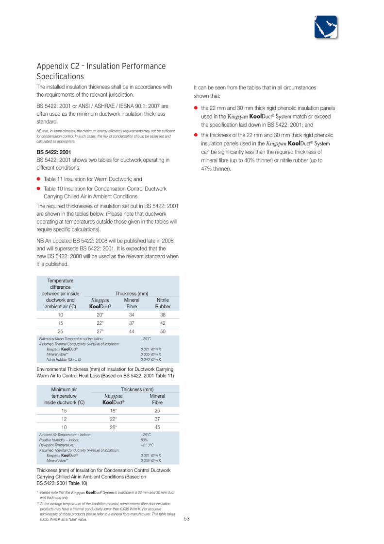
53
It can be seen from the tables that in all circumstancesshown that:
� the 22 mm and 30 mm thick rigid phenolic insulation panelsused in the Kingspan KoolDuct® System match or exceedthe specification laid down in BS 5422: 2001; and
� the thickness of the 22 mm and 30 mm thick rigid phenolicinsulation panels used in the Kingspan KoolDuct® Systemcan be significantly less than the required thickness ofmineral fibre (up to 40% thinner) or nitrile rubber (up to47% thinner).
Appendix C2 – Insulation PerformanceSpecificationsThe installed insulation thickness shall be in accordance withthe requirements of the relevant jurisdiction.
BS 5422: 2001 or ANSI / ASHRAE / IESNA 90.1: 2007 areoften used as the minimum ductwork insulation thicknessstandard.
NB that, in some climates, the minimum energy efficiency requirements may not be sufficientfor condensation control. In such cases, the risk of condensation should be assessed andcalculated as appropriate.
BS 5422: 2001BS 5422: 2001 shows two tables for ductwork operating indifferent conditions:
� Table 11 Insulation for Warm Ductwork; and
� Table 10 Insulation for Condensation Control DuctworkCarrying Chilled Air in Ambient Conditions.
The required thicknesses of insulation set out in BS 5422: 2001are shown in the tables below. (Please note that ductworkoperating at temperatures outside those given in the tables willrequire specific calculations).
NB An updated BS 5422: 2008 will be published late in 2008and will supersede BS 5422: 2001. It is expected that thenew BS 5422: 2008 will be used as the relevant standard whenit is published.
Temperaturedifference
between air inside Thickness (mm)ductwork and Kingspan Mineral Nitrileambient air (˚C) KoolDuct® Fibre Rubber
10 20* 34 38
15 22* 37 42
25 27* 44 50Estimated Mean Temperature of Insulation: +20°CAssumed Thermal Conductivity (k–value) of Insulation:
Kingspan KoolDuct® 0.021 W/m.KMineral Fibre** 0.035 W/m.KNitrile Rubber (Class 0) 0.040 W/m.K
Environmental Thickness (mm) of Insulation for Ductwork CarryingWarm Air to Control Heat Loss (Based on BS 5422: 2001 Table 11)
Minimum air Thickness (mm)temperature Kingspan Mineral
inside ductwork (˚C) KoolDuct® Fibre
15 16* 25
12 22* 37
10 28* 45Ambient Air Temperature – Indoor: +25°CRelative Humidity – Indoor: 80%Dewpoint Temperature: +21.3°CAssumed Thermal Conductivity (k–value) of Insulation:
Kingspan KoolDuct® 0.021 W/m.KMineral Fibre** 0.035 W/m.K
Thickness (mm) of Insulation for Condensation Control DuctworkCarrying Chilled Air in Ambient Conditions (Based onBS 5422: 2001 Table 10)
* Please note that the Kingspan KoolDuct® System is available in a 22 mm and 30 mm ductwall thickness only.
** At the average temperature of the insulation material, some mineral fibre duct insulationproducts may have a thermal conductivity lower than 0.035 W/m.K. For accuratethicknesses of those products please refer to a mineral fibre manufacturer. This table takes0.035 W/m.K as a “safe” value.
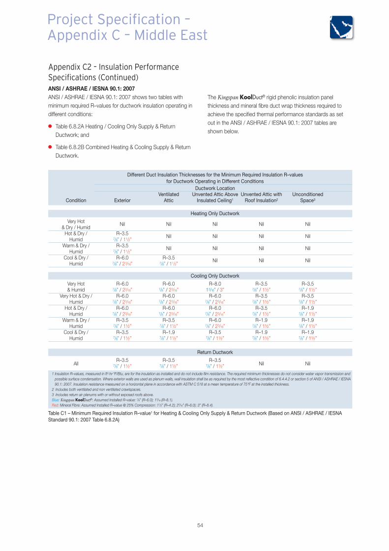
54
Appendix C2 – Insulation PerformanceSpecifications (Continued)ANSI / ASHRAE / IESNA 90.1: 2007ANSI / ASHRAE / IESNA 90.1: 2007 shows two tables withminimum required R–values for ductwork insulation operating indifferent conditions:
� Table 6.8.2A Heating / Cooling Only Supply & ReturnDuctwork; and
� Table 6.8.2B Combined Heating & Cooling Supply & ReturnDuctwork.
The Kingspan KoolDuct® rigid phenolic insulation panelthickness and mineral fibre duct wrap thickness required toachieve the specified thermal performance standards as setout in the ANSI / ASHRAE / IESNA 90.1: 2007 tables areshown below.
Different Duct Insulation Thicknesses for the Minimum Required Insulation R–valuesfor Ductwork Operating in Different Conditions
Ductwork LocationVentilated Unvented Attic Above Unvented Attic with Unconditioned
Condition Exterior Attic Insulated Ceiling1 Roof Insulation2 Space3
Heating Only Ductwork
Very Hot& Dry / Humid
Nil Nil Nil Nil Nil
Hot & Dry / R–3.5Humid 7/8” / 11/2”
Nil Nil Nil Nil
Warm & Dry / R–3.5Humid 7/8” / 11/2”
Nil Nil Nil Nil
Cool & Dry / R–6.0 R–3.5Humid 7/8” / 23/16” 7/8” / 11/2”
Nil Nil Nil
Cooling Only Ductwork
Very Hot R–6.0 R–6.0 R–8.0 R–3.5 R–3.5& Humid 7/8” / 23/16” 7/8” / 23/16” 13/16” / 3” 7/8” / 1½” 7/8” / 1½”
Very Hot & Dry / R–6.0 R–6.0 R–6.0 R–3.5 R–3.5Humid 7/8” / 23/16” 7/8” / 23/16” 7/8” / 23/16” 7/8” / 1½” 7/8” / 1½”
Hot & Dry / R–6.0 R–6.0 R–6.0 R–3.5 R–1.9Humid 7/8” / 23/16” 7/8” / 23/16” 7/8” / 23/16” 7/8” / 1½” 7/8” / 1½”
Warm & Dry / R–3.5 R–3.5 R–6.0 R–1.9 R–1.9Humid 7/8” / 1½” 7/8” / 1½” 7/8” / 23/16” 7/8” / 1½” 7/8” / 1½”
Cool & Dry / R–3.5 R–1.9 R–3.5 R–1.9 R–1.9Humid 7/8” / 1½” 7/8” / 1½” 7/8” / 1½” 7/8” / 1½” 7/8” / 1½”
Return Ductwork
R–3.5 R–3.5 R–3.5All 7/8” / 1½” 7/8” / 1½” 7/8” / 1½” Nil Nil
1 Insulation R–values, measured in ft2.hr.°F/Btu, are for the insulation as installed and do not include film resistance. The required minimum thicknesses do not consider water vapor transmission andpossible surface condensation. Where exterior walls are used as plenum walls, wall insulation shall be as required by the most reflective condition of 6.4.4.2 or section 5 of ANSI / ASHRAE / IESNA90.1: 2007. Insulation resistance measured on a horizontal plane in accordance with ASTM C 518 at a mean temperature of 75°F at the installed thickness.
2 Includes both ventilated and non ventilated crawlspaces.3 Includes return air plenums with or without exposed roofs above.Blue: Kingspan KoolDuct®: Assumed Installed R–value: 7/8” (R–6.0); 13/16 (R–8.1).Red: Mineral Fibre: Assumed Installed R–value @ 25% Compression: 11/2” (R–4.2); 23/16” (R–6.0); 3” (R–8.4).
Table C1 – Minimum Required Insulation R–value1 for Heating & Cooling Only Supply & Return Ductwork (Based on ANSI / ASHRAE / IESNAStandard 90.1: 2007 Table 6.8.2A)
Project Specification –Appendix C – Middle East
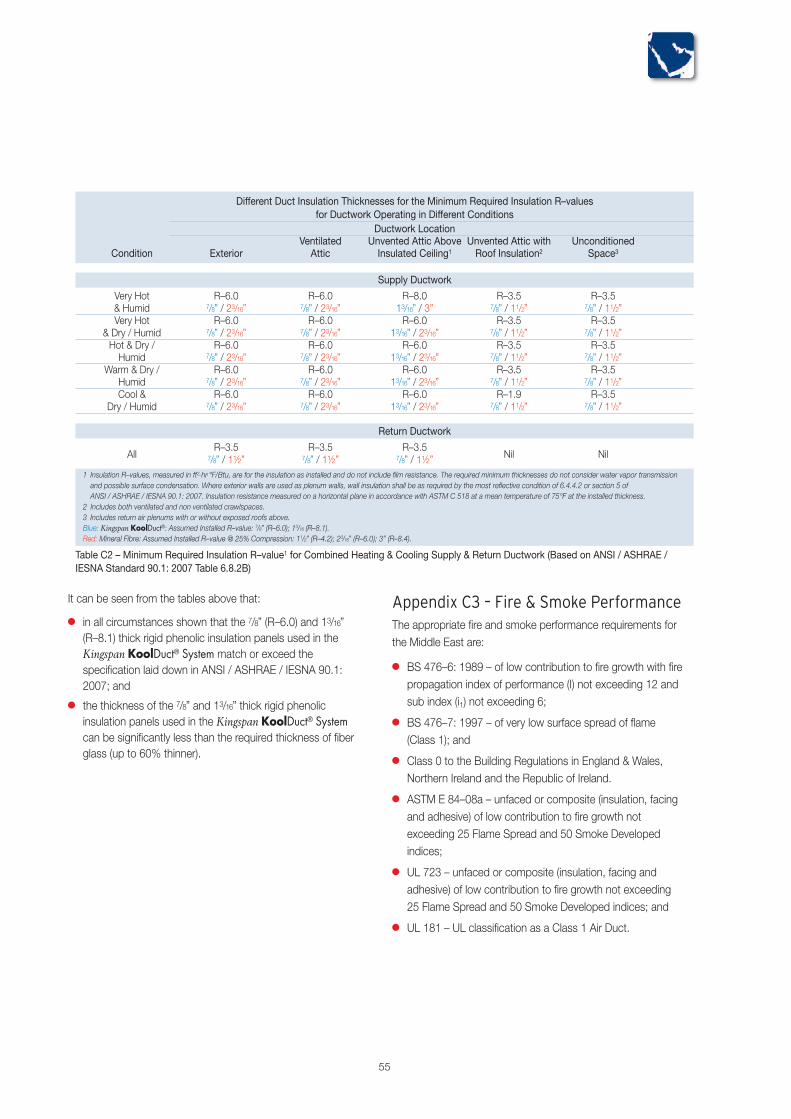
55
It can be seen from the tables above that:
� in all circumstances shown that the 7/8” (R–6.0) and 13/16”(R–8.1) thick rigid phenolic insulation panels used in theKingspan KoolDuct® System match or exceed thespecification laid down in ANSI / ASHRAE / IESNA 90.1:2007; and
� the thickness of the 7/8” and 13/16” thick rigid phenolicinsulation panels used in the Kingspan KoolDuct® Systemcan be significantly less than the required thickness of fiberglass (up to 60% thinner).
Different Duct Insulation Thicknesses for the Minimum Required Insulation R–valuesfor Ductwork Operating in Different Conditions
Ductwork LocationVentilated Unvented Attic Above Unvented Attic with Unconditioned
Condition Exterior Attic Insulated Ceiling1 Roof Insulation2 Space3
Supply Ductwork
Very Hot R–6.0 R–6.0 R–8.0 R–3.5 R–3.5& Humid 7/8” / 23/16” 7/8” / 23/16” 13/16” / 3” 7/8” / 11/2” 7/8” / 11/2”Very Hot R–6.0 R–6.0 R–6.0 R–3.5 R–3.5
& Dry / Humid 7/8” / 23/16” 7/8” / 23/16” 13/16” / 23/16” 7/8” / 11/2” 7/8” / 11/2”Hot & Dry / R–6.0 R–6.0 R–6.0 R–3.5 R–3.5Humid 7/8” / 23/16” 7/8” / 23/16” 13/16” / 23/16” 7/8” / 11/2” 7/8” / 11/2”
Warm & Dry / R–6.0 R–6.0 R–6.0 R–3.5 R–3.5Humid 7/8” / 23/16” 7/8” / 23/16” 13/16” / 23/16” 7/8” / 11/2” 7/8” / 11/2”Cool & R–6.0 R–6.0 R–6.0 R–1.9 R–3.5
Dry / Humid 7/8” / 23/16” 7/8” / 23/16” 13/16” / 23/16” 7/8” / 11/2” 7/8” / 11/2”
Return Ductwork
R–3.5 R–3.5 R–3.5All 7/8” / 1½” 7/8” / 1½” 7/8” / 1½” Nil Nil
1 Insulation R–values, measured in ft2.hr.°F/Btu, are for the insulation as installed and do not include film resistance. The required minimum thicknesses do not consider water vapor transmissionand possible surface condensation. Where exterior walls are used as plenum walls, wall insulation shall be as required by the most reflective condition of 6.4.4.2 or section 5 ofANSI / ASHRAE / IESNA 90.1: 2007. Insulation resistance measured on a horizontal plane in accordance with ASTM C 518 at a mean temperature of 75°F at the installed thickness.
2 Includes both ventilated and non ventilated crawlspaces.3 Includes return air plenums with or without exposed roofs above.Blue: Kingspan KoolDuct®: Assumed Installed R–value: 7/8” (R–6.0); 13/16 (R–8.1).Red: Mineral Fibre: Assumed Installed R–value @ 25% Compression: 11/2” (R–4.2); 23/16” (R–6.0); 3” (R–8.4).
Table C2 – Minimum Required Insulation R–value1 for Combined Heating & Cooling Supply & Return Ductwork (Based on ANSI / ASHRAE /IESNA Standard 90.1: 2007 Table 6.8.2B)
Appendix C3 – Fire & Smoke PerformanceThe appropriate fire and smoke performance requirements forthe Middle East are:
� BS 476–6: 1989 – of low contribution to fire growth with firepropagation index of performance (I) not exceeding 12 andsub index (i1) not exceeding 6;
� BS 476–7: 1997 – of very low surface spread of flame(Class 1); and
� Class 0 to the Building Regulations in England & Wales,Northern Ireland and the Republic of Ireland.
� ASTM E 84–08a – unfaced or composite (insulation, facingand adhesive) of low contribution to fire growth notexceeding 25 Flame Spread and 50 Smoke Developedindices;
� UL 723 – unfaced or composite (insulation, facing andadhesive) of low contribution to fire growth not exceeding25 Flame Spread and 50 Smoke Developed indices; and
� UL 181 – UL classification as a Class 1 Air Duct.
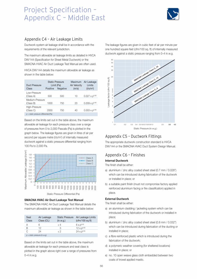
Appendix C5 – Ductwork FittingsThe appropriate ductwork construction standard is HVCADW/144 or the SMACNA HVAC Duct System Design Manual.
Appendix C6 – FinishesInternal DuctworkThe finish shall be either:
a) aluminium / zinc alloy coated sheet steel (0.7 mm / 0.028”)which can be introduced during fabrication of the ductworkor installed in place; or
b) a suitable paint finish (must not compromise factory appliedreinforced aluminium facing or fire classification) applied inplace.
External DuctworkThe finish shall be either:
a) an aluminium cladding / jacketing system which can beintroduced during fabrication of the ductwork or installed inplace;
b) aluminium / zinc alloy coated sheet steel (0.8 mm / 0.032”)which can be introduced during fabrication of the ducting orinstalled in place;
c) a fibre reinforced plastic which is introduced during thefabrication of the ductwork;
d) a polymeric weather covering (for sheltered locations)installed in place; or
e) no. 10 open weave glass cloth embedded between twocoats of trowel applied mastic.
56
SMACNA HVAC Air Duct Leakage Test ManualThe SMACNA HVAC Air Duct Leakage Test Manual details themaximum allowable air leakage as shown in the table below:
Appendix C4 – Air Leakage LimitsDuctwork system air leakage shall be in accordance with therequirements of the relevant jurisdiction.
The maximum allowable air leakage limits as detailed in HVCADW/144 (Specification for Sheet Metal Ductwork) or theSMACNA HVAC Air Duct Leakage Test Manual are often used.
HVCA DW/144 details the maximum allowable air leakage asshown in the table below:
Static Pressure Maximum Air LeakageDuct Pressure Limit (Pa) Air Velocity LimitsClass Positive Negative (m/s) (l/s/m2)
Low–Pressure(Class A) 500 500 10 0.027 x p0.65
Medium–Pressure(Class B) 1000 750 20 0.009 x p0.65
High–Pressure(Class C) 2000 750 40 0.003 x p0.65
p = static pressure differential (Pa)
Based on the limits set out in the table above, the maximumallowable air leakage for each pressure class over a rangeof pressures from 0 to 2,000 Pascals (Pa) is plotted in thegraph below. The leakage figures are given in litres of air persecond per square metre (l/s/m2) of internally measuredductwork against a static pressure differential ranging from100 Pa to 2,000 Pa.
Seal Air Leakage Static Pressure Air Leakage LimitsClass Class (CL) (in.w.g.) (cfm/100 sq.ft)
A 6 ≥ 4 6 x p0.65
B 12 3 12 x p0.65
C 24 ≤ 2 24 x p0.65
p = static pressure (in.w.g)
Based on the limits set out in the table above, the maximumallowable air leakage for each pressure and seal class isplotted in the graph above right over a range of pressures from0–4 in.w.g.
The leakage figures are given in cubic feet of air per minute perone hundred square feet (cfm/100 sq. ft) of internally measuredductwork against a static pressure ranging from 0–4 in.w.g.
Project Specification –Appendix C – Middle East
Appendix C7 – Testing for Air LeakageDuctwork air leakage testing shall be carried out in accordancewith the requirements of the relevant jurisdiction.
Ductwork leakage testing shall be carried out in accordancewith the procedures set out in HVCA DW/144 or the SMACNAHVAC Air Duct Leakage Test Manual
HVCA DW/143HVCA DW/143 recommends the range and frequency oftesting that it deems to be satisfactory.
It recommends the following:
� high pressure ducts (Class C) – all tested;
� medium pressure ducts (Class B) – 10% of the ductworkselected at random and tested; and
� low pressure ducts (Class A) – untested.
It is also recommended:
� for medium pressure ducts, in the event of test failure of therandomly selected section, the designer shall have the rightto select two further sections at random for testing. Wheresuccessive failures are identified there shall be a right torequire the contractor to apply remedial attention to thecomplete ductwork system; and
� in general for all ducts tested, that the air leakage rate for anysection shall not be in excess of the permitted rate (as statedin HVCA DW/144) for that section. If a first test producesleakage in excess of the permitted maximum, the sectionshall be resealed and retested until a leakage not greaterthan the permitted maximum for that section is achieved.
SMACNA HVAC Air Duct Leakage Test ManualThe SMACNA HVAC Air Duct Leakage Test Manual does notrequire testing for air leakage where adequate methods ofassembly and sealing are used.
It recommends the following:
� high pressure ducts ≥ 4 in.w.g. (≥ 1000 Pa) – tested,if justified by the designer; and
� low – medium pressure ducts ≤ 3 in.w.g. (≤ 750 Pa) –untested.
Appendix C8– Standards / ReferencesBritish StandardsBS 476–6: 1989Fire tests on building materials and structures. Method of testfor fire propagation for products
BS 476–7: 1997Fire tests on building materials and structures. Method of testto determine the classification of the surface spread of flame ofproducts
BS 6401: 1983Method for measurement, in the laboratory, of the specificoptical density of smoke generated by materials.
BS 5422: 2001Method for specifying thermal insulating materials for pipes,tanks, vessels, ductwork and equipment operating within thetemperature range –40ºC to +700ºC
BS EN 826:1996Thermal insulating products for building applications.Determination of compression behaviour
BS EN 12086:1997Thermal insulating products for building applications.Determination of water vapour transmission properties
BS EN ISO 4590: 2003Rigid cellular plastics. Determination of the volume percentageof open cells and of closed cells
BS EN ISO 9001: 2000Quality management systems. Requirements
BS EN ISO 14001: 2004Environmental management systems. Requirements withguidance for use)
American StandardsASTM C 518: 2004Standard Test Method for Steady–State Thermal TransmissionProperties by Means of the Heat Flow Meter Apparatus
ASTM E96 / E96M–05Standard Test Methods for Water Vapour Transmission ofMaterials
ASTM E 84–08aStandard Test Method for Surface Burning Characteristics ofBuilding Materials
UL 723Test for Surface Burning Characteristics of Building Materials
UL 181Standard for Safety Factory Made Air Ducts and Connectors
Other ReferencesHVCA DW/144Specification for Sheet Metal Ductwork
HVCA DW/143A practical guide to Ductwork Leakage Testing
SMACNA HVAC Duct System Design Manual
SMACNA HVAC Air Duct Leakage Test Manual
ANSI / ASHRAE / IESNA 90.1: 2007Energy Standard for Buildings Except Low–Rise ResidentialBuildings Sections 5 & 6
57
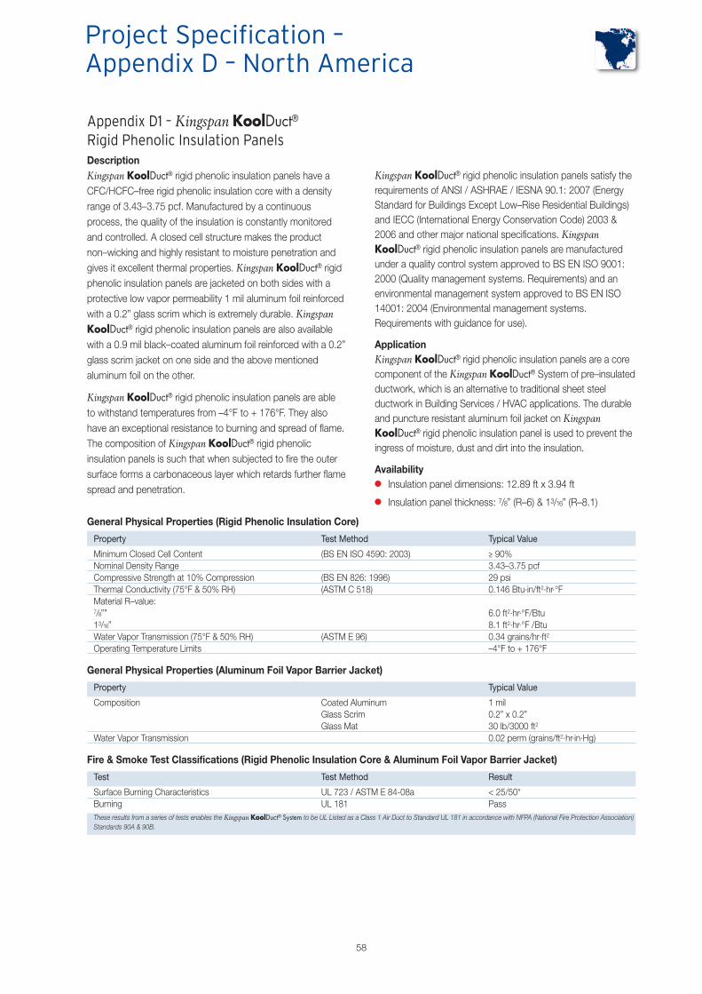
58
Project Specification –Appendix D – North America
Appendix D1 – Kingspan KoolDuct®Rigid Phenolic Insulation PanelsDescriptionKingspan KoolDuct® rigid phenolic insulation panels have aCFC/HCFC–free rigid phenolic insulation core with a densityrange of 3.43–3.75 pcf. Manufactured by a continuousprocess, the quality of the insulation is constantly monitoredand controlled. A closed cell structure makes the productnon–wicking and highly resistant to moisture penetration andgives it excellent thermal properties. Kingspan KoolDuct® rigidphenolic insulation panels are jacketed on both sides with aprotective low vapor permeability 1 mil aluminum foil reinforcedwith a 0.2” glass scrim which is extremely durable. KingspanKoolDuct® rigid phenolic insulation panels are also availablewith a 0.9 mil black–coated aluminum foil reinforced with a 0.2”glass scrim jacket on one side and the above mentionedaluminum foil on the other.
Kingspan KoolDuct® rigid phenolic insulation panels are ableto withstand temperatures from –4°F to + 176°F. They alsohave an exceptional resistance to burning and spread of flame.The composition of Kingspan KoolDuct® rigid phenolicinsulation panels is such that when subjected to fire the outersurface forms a carbonaceous layer which retards further flamespread and penetration.
Kingspan KoolDuct® rigid phenolic insulation panels satisfy therequirements of ANSI / ASHRAE / IESNA 90.1: 2007 (EnergyStandard for Buildings Except Low–Rise Residential Buildings)and IECC (International Energy Conservation Code) 2003 &2006 and other major national specifications. KingspanKoolDuct® rigid phenolic insulation panels are manufacturedunder a quality control system approved to BS EN ISO 9001:2000 (Quality management systems. Requirements) and anenvironmental management system approved to BS EN ISO14001: 2004 (Environmental management systems.Requirements with guidance for use).
ApplicationKingspan KoolDuct® rigid phenolic insulation panels are a corecomponent of the Kingspan KoolDuct® System of pre–insulatedductwork, which is an alternative to traditional sheet steelductwork in Building Services / HVAC applications. The durableand puncture resistant aluminum foil jacket on KingspanKoolDuct® rigid phenolic insulation panel is used to prevent theingress of moisture, dust and dirt into the insulation.
Availability� Insulation panel dimensions: 12.89 ft x 3.94 ft
� Insulation panel thickness: 7/8” (R–6) & 13/16” (R–8.1)
General Physical Properties (Rigid Phenolic Insulation Core)
Property Test Method Typical Value
Minimum Closed Cell Content (BS EN ISO 4590: 2003) ≥ 90%Nominal Density Range 3.43–3.75 pcfCompressive Strength at 10% Compression (BS EN 826: 1996) 29 psiThermal Conductivity (75°F & 50% RH) (ASTM C 518) 0.146 Btu.in/ft2.hr.°FMaterial R–value:7/8”” 6.0 ft2.hr.°F/Btu13/16” 8.1 ft2.hr.°F /BtuWater Vapor Transmission (75°F & 50% RH) (ASTM E 96) 0.34 grains/hr·ft2
Operating Temperature Limits –4°F to + 176°F
General Physical Properties (Aluminum Foil Vapor Barrier Jacket)
Property Typical Value
Composition Coated Aluminum 1 milGlass Scrim 0.2” x 0.2”Glass Mat 30 lb/3000 ft2
Water Vapor Transmission 0.02 perm (grains/ft2.hr.in.Hg)
Fire & Smoke Test Classifications (Rigid Phenolic Insulation Core & Aluminum Foil Vapor Barrier Jacket)
Test Test Method Result
Surface Burning Characteristics UL 723 / ASTM E 84-08a < 25/50*Burning UL 181 PassThese results from a series of tests enables the Kingspan KoolDuct® System to be UL Listed as a Class 1 Air Duct to Standard UL 181 in accordance with NFPA (National Fire Protection Association)Standards 90A & 90B.

Appendix D2 – Insulation PerformanceSpecificationsThe installed insulation thickness shall be in accordance withthe requirements of the relevant jurisdiction. (Consult the DOE(US Department of Energy) ComCheck / ResCheck or therelevant authority for applicable codes / standards).
ANSI / ASHRAE / IESNA 90.1: 2007 and IECC 2003 & 2006are enforced by many, but not all, North American jurisdictionsas the minimum ductwork insulation thickness standard.
ANSI / ASHRAE / IESNA 90.1: 2007 shows two tables withminimum required R–values for ductwork insulation operatingin different climate zones and locations:
� Table 6.8.2A Heating / Cooling Only Supply & ReturnDuctwork; and
� Table 6.8.2B Combined Heating & Cooling Supply & ReturnDuctwork.
The different climate zones are shown on the map to the right.
The Kingspan KoolDuct® rigid phenolic insulation panelthickness and fiber glass duct wrap thickness required toachieve the specified thermal performance standards as setout in the ANSI / ASHRAE / IESNA 90.1: 2007 tables areshown below.
NB that, in some climates, the minimum energy efficiency requirements may not be sufficientfor condensation control. In such cases, the risk of condensation should be assessed andcalculated as appropriate.
ANSI / ASHRAE / IESNA Standard 90.1: 2007 Climate Zone Map forUS Locations
59
Warm / humidbelow line
Zone 1 includes Hawaii, Guam, Puerto Rico, and the Virgin islands
All of Alaska in Zone 7 except for the following Boroughs in Zone 8:
Bethel Northwest Artic DellinghamSoutheast Fairbanks Fairbanks N. Star Wade HamptonNome Yukon–Koyukuk North slope
Dry (B) Moist (A)Marine (C)
Different Duct Insulation Thicknesses for the Minimum Required Insulation R–values for Each Climate ZoneDuctwork Location
Climate Exterior Ventilated Unvented Attic Above Unvented Attic with UnconditionedZone Attic Insulated Ceiling1 Roof Insulation2 Space3
Heating Only Ductwork
R–6.0 R–6.0 R–8.0 R–3.5 R–3.51 7/8” / 23/16” 7/8” / 23/16” 13/16” / 3” 7/8” / 11/2” 7/8” / 11/2”
R–6.0 R–6.0 R–6.0 R–3.5 R–3.52 7/8” / 23/16” 7/8” / 23/16” 7/8” / 23/16” 7/8” / 11/2” 7/8” / 11/2”
R–6.0 R–6.0 R–6.0 R–3.5 R–3.53 7/8” / 23/16” 7/8” / 23/16” 7/8” / 23/16” 7/8” / 11/2” 7/8” / 11/2”
R–6.0 R–6.0 R–6.0 R–3.5 R–3.54 7/8” / 23/16” 7/8” / 23/16” 7/8” / 23/16” 7/8” / 11/2” 7/8” / 11/2”
R–6.0 R–6.0 R–6.0 R–1.9 R–3.55 7/8” / 23/16” 7/8” / 23/16” 7/8” / 23/16” 7/8” / 11/2” 7/8” / 11/2”
R–8.0 R–6.0 R–6.0 R–1.9 R–3.56 13/16” / 3” 7/8” / 23/16” 7/8” / 23/16” 7/8” / 11/2” 7/8” / 11/2”
R–8.0 R–6.0 R–6.0 R–1.9 R–3.57 13/16” / 3” 7/8” / 23/16” 7/8” / 23/16” 7/8” / 11/2” 7/8” / 11/2”
R–8.0 R–8.0 R–8.0 R–1.9 R–6.08 13/16” / 3” 13/16” / 3” 13/16” / 3” 7/8” / 11/2” 7/8” / 23/16”
Return Duct
R–3.5 R–3.5 R–3.5All 7/8” / 1½” 7/8” / 1½” 7/8” / 1½” Nil Nil
1 Insulation R–values, measured in ft2.hr.°F/Btu, are for the insulation as installed and do not include film resistance. The required minimum thicknesses do not consider water vaportransmission and possible surface condensation. Where exterior walls are used as plenum walls, wall insulation shall be as required by the most reflective condition of 6.4.4.2 or section 5of ANSI / ASHRAE / IESNA 90.1: 2007. Insulation resistance measured on a horizontal plane in accordance with ASTM C 518 at a mean temperature of 75°F at the installed thickness.
2 Includes both ventilated and non ventilated crawlspaces.3 Includes return air plenums with or without exposed roofs above.Blue: Kingspan KoolDuct®: Assumed Installed R–value: 7/8” (R–6.0); 13/16 (R–8.1).Red: Fiber Glass: Assumed Installed R–value @ 25% Compression: 11/2” (R–4.2); 23/16” (R–6.0); 3” (R–8.4).
Table D1 – Minimum Required Insulation R–value1 for Combined Heating & Cooling Supply & Return Ductwork (Based on ANSI / ASHRAE /IESNA Standard 90.1: 2007 Table 6.8.2B)

60
It can be seen from the tables above that:
� in all circumstances shown that the 7/8” (R–6.0) and 13/16”(R–8.1) thick rigid phenolic insulation panels used in theKingspan KoolDuct® System match or exceed thespecification laid down in ANSI / ASHRAE / IESNA 90.1:2007 and IECC 2003 & 2006; and
� the thickness of the 7/8” and 13/16” thick rigid phenolicinsulation panels used in the Kingspan KoolDuct® Systemcan be significantly less than the required thickness of fiberglass (up to 60% thinner).
Different Duct Insulation Thicknesses for the Minimum Required Insulation R–values for Each Climate ZoneDuctwork Location
Climate Exterior Ventilated Unvented Attic Above Unvented Attic with UnconditionedZone Attic Insulated Ceiling1 Roof Insulation2 Space3
Heating Only Ductwork
1 & 2 Nil Nil Nil Nil NilR–3.5
3 7/8” / 11/2” Nil Nil Nil Nil
R–3.54 7/8” / 11/2” Nil Nil Nil Nil
R–6.0 R–3.55 7/8” / 23/16” 7/8” / 11/2” Nil Nil Nil
R–6.0 R–6.0 R–3.56 7/8” / 23/16” 7/8” / 23/16” 7/8” / 11/2” Nil Nil
R–8.0 R–6.0 R–6.0 R–3.57 13/16” / 3” 7/8” / 23/16” 7/8” / 23/16” Nil 7/8” / 11/2”
R–8.0 R–8.0 R–8.0 R–6.08 13/16” / 3” 13/16” / 3” 13/16” / 3” Nil 7/8” / 23/16”
Cooling Only Ductwork
R–6.0 R–6.0 R–8.0 R–3.5 R–3.51 7/8” / 23/16” 7/8” / 23/16” 13/16” / 3” 7/8” / 1½” 7/8” / 1½”
R–6.0 R–6.0 R–6.0 R–3.5 R–3.52 7/8” / 23/16” 7/8” / 23/16” 7/8” / 23/16” 7/8” / 1½” 7/8” / 1½”
R–6.0 R–6.0 R–6.0 R–3.5 R–1.93 7/8” / 23/16” 7/8” / 23/16” 7/8” / 23/16” 7/8” / 1½” 7/8” / 1½”
R–3.5 R–3.5 R–6.0 R–1.9 R–1.94 7/8” / 1½” 7/8” / 1½” 7/8” / 23/16” 7/8” / 1½” 7/8” / 1½”
R–3.5 R–1.9 R–3.5 R–1.9 R–1.95 & 6 7/8” / 1½” 7/8” / 1½” 7/8” / 1½” 7/8” / 1½” 7/8” / 1½”
R–1.9 R–1.9 R–1.9 R–1.9 R–1.97 & 8 7/8” / 1½” 7/8” / 1½” 7/8” / 1½” 7/8” / 1½” 7/8” / 1½”
Return Ductwork
R–3.5 R–3.5 R–3.5All 7/8” / 1½” 7/8” / 1½” 7/8” 1½” Nil Nil
1 Insulation R–values, measured in ft2.hr.°F/Btu, are for the insulation as installed and do not include film resistance. The required minimum thicknesses do not consider water vaportransmission and possible surface condensation. Where exterior walls are used as plenum walls, wall insulation shall be as required by the most reflective condition of 6.4.4.2 or section 5of ANSI / ASHRAE / IESNA 90.1: 2007. Insulation resistance measured on a horizontal plane in accordance with ASTM C 518 at a mean temperature of 75°F at the installed thickness.
2 Includes both ventilated and non ventilated crawlspaces.3 Includes return air plenums with or without exposed roofs above.Blue: Kingspan KoolDuct®: Assumed Installed R–value: 7/8” (R–6.0); 13/16 (R–8.1).Red: Fiber Glass: Assumed Installed R–value @ 25% Compression: 11/2” (R–4.2); 23/16” (R–6.0); 3” (R–8.4).
Table D2 – Minimum Required Insulation R–value1 for Heating & Cooling Only Supply & Return Ductwork (Based on ANSI / ASHRAE / IESNAStandard 90.1: 2007 Table 6.8.2A)
Project Specification –Appendix D – North America
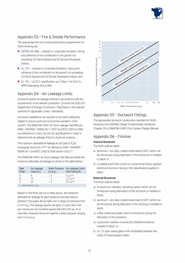
61
Appendix D3 – Fire & Smoke PerformanceThe appropriate fire and smoke performance requirements forNorth America are:
� ASTM E 84–08a – unfaced or composite (insulation, facingand adhesive) of low contribution to fire growth notexceeding 25 Flame Spread and 50 Smoke Developedindices;
� UL 723 – unfaced or composite (insulation, facing andadhesive) of low contribution to fire growth not exceeding25 Flame Spread and 50 Smoke Developed indices; and
� UL 181 – UL/ULC classification as a Class 1 Air Duct toNFPA Standards 90A & 90B.
Appendix D4 – Air Leakage LimitsDuctwork system air leakage shall be in accordance with therequirements of the relevant jurisdiction. (Consult the DOE (USDepartment of Energy) ComCheck / ResCheck or the relevantauthority for applicable codes / standards).
Ductwork installations are required to be made sufficientlyairtight to ensure quiet and economical operation of thesystem. The SMACNA HVAC Air Duct Leakage Test Manual,ANSI / ASHRAE / IESNA 90.1: 2007 and IECC 2003 & 2006are referred to in many, but not all, specifications in order todetermine the air leakage limits for ductwork systems.
The maximum allowable air leakage for all Class 6 (CL6)rectangular ducts is 6 x P0.65 as defined by ANSI / ASHRAE /IESNA 90.1 and IECC 2003 & 2006 section 503.2.7.
The SMACNA HVAC Air Duct Leakage Test Manual details themaximum allowable air leakage as shown in the table below:
Appendix D5 – Ductwork FittingsThe appropriate ductwork construction standard for NorthAmerica is the ASHRAE Design Fundamentals HandbookChapter 35 or SMACNA HVAC Duct System Design Manual.
Appendix D6 – FinishesInternal DuctworkThe finish shall be either:
a) aluminum / zinc alloy coated sheet steel (0.024”) which canbe introduced during fabrication of the ductwork or installedin place; or
b) a suitable paint finish (must not compromise factory appliedreinforced aluminum facing or fire classification) applied inplace.
External DuctworkThe finish shall be either:
a) an aluminum cladding / jacketing system which can beintroduced during fabrication of the ductwork or installed inplace;
b) aluminum / zinc alloy coated sheet steel (0.032”) which canbe introduced during fabrication of the ducting or installed inplace;
c) a fiber reinforced plastic which is introduced during thefabrication of the ductwork;
d) a polymeric weather covering (for sheltered locations)installed in place; or
e) no. 10 open weave glass cloth embedded between twocoats of trowel applied mastic.
Seal Air Leakage Static Pressure Air Leakage LimitsClass Class (CL) (in.w.g.) (cfm/100 sq.ft)
A 6 ≥ 4 6 x p0.65
B 12 3 12 x p0.65
C 24 ≤ 2 24 x p0.65
p = static pressure (in.w.g)
Based on the limits set out in table above, the maximumallowable air leakage for each pressure and seal class isplotted in the graph above right over a range of pressures from0–4 in.w.g. The leakage figures are given in cubic feet of airper minute per one hundred square feet (cfm/100 sq. ft) ofinternally measured ductwork against a static pressure rangingfrom 0–4 in.w.g.

British StandardsBS EN 826:1996Thermal insulating products for building applications.Determination of compression behaviour
BS EN ISO 4590: 2003Rigid cellular plastics. Determination of the volume percentageof open cells and of closed cells
BS EN ISO 9001: 2000Quality management systems. Requirements
BS EN ISO 14001: 2004Environmental management systems. Requirements withguidance for use)
Other ReferencesUS Department of Energy (DOE)ComCheck & ResCheck
ANSI / ASHRAE / IESNA 90.1: 2007Energy Standard for Buildings Except Low–Rise ResidentialBuildings Sections 5 & 6
ASHRAE Design Fundamentals Handbook Chapter 35
SMACNA HVAC Duct System Design Manual
SMACNA HVAC Duct Construction Standard
SMACNA HVAC Air Duct Leakage Test manual
Building CodesThe IECC (International Energy Conservation Code) 2003 &2006
The IECC (International Energy Conservation Code) 2003 &2006 503.2.7
Appendix D7 – Testing for Air LeakageDuctwork air leakage testing shall be carried out in accordancewith the requirements of the relevant jurisdiction.
ANSI / ASHRAE / IESNA 90.1 requires that ductwork designedto operate at static pressures > 3 in.w.g be tested for airleakage and that testing is performed on ≥ 25% of the totalinstalled duct area. It refers to the SMACNA HVAC Air DuctLeakage Manual as an industry accepted test procedure for airleakage.
The SMACNA HVAC Air Duct Leakage Test Manual does notrequire testing for air leakage where adequate methods ofassembly and sealing are used. It recommends the following:
� high pressure ducts ≥ 4 in.w.g. – tested, if justified by thedesigner; and
� low – medium pressure ducts ≤ 3 in.w.g. – untested.
Appendix D8 – Standards / ReferencesAmerican StandardsASTM C 518: 2004Standard Test Method for Steady–State Thermal TransmissionProperties by Means of the Heat Flow Meter Apparatus
ASTM E96 / E96M–05Standard Test Methods for Water Vapor Transmission ofMaterials
ASTM E 84–08aStandard Test Method for Surface Burning Characteristics ofBuilding Materials
UL 723Test for Surface Burning Characteristics of Building Materials
NFPA 90AStandard for the Installation of Air Conditioning and VentilatingSystems
NFPA 90BStandard for the Installation of Warm Air Heating andAir–Conditioning Systems
UL/ULC 181Standard for Safety Factory Made Air Ducts and Connectors
62
Project Specification –Appendix D – North America
Contact Details
UK & IrelandFor all enquiries, please contact Kingspan Insulation Ltd. as follows:
UK – Tel: +44 (0) 870 850 8555– Fax: +44 (0) 870 850 8666– email: [email protected]
Ireland – Tel: +353 (0) 42 97 54200– Fax: +353 (0) 42 97 54299– email: [email protected]
North AmericaFor all enquiries, please contact Kingspan Insulation Ltd. as follows:
– Tel: +44 (0) 870 850 8555– Fax: +44 (0) 870 850 8666– email: [email protected]
AustraliaFor all enquiries, please contact Kingspan Insulation Ltd. as follows:
– 38–52 Dunhevan Circuit, St. Marys, NSW 2760– Tel: +61 (0) 2 9673 5069– Fax: +61 (0) 2 9673 5068– email: [email protected]
Middle EastFor all enquiries, please contact Kingspan Insulation Ltd. as follows:
– Tel: +44 (0) 870 850 8555– Fax: +44 (0) 870 850 8666– email: [email protected]
Kingspan Insulation Ltd. reserves the right to amend product specifications without prior notice.Product thicknesses shown in this document should not be taken as being availableex–stock and reference should be made to the current Kingspan Insulation price–list or advicesought from Kingspan Insulation’s Customer Service Department (see above left). Theinformation, technical details and fixing instructions etc. included in this literature are given ingood faith and apply to uses described. Recommendations for use should be verified as to thesuitability and compliance with actual requirements, specifications and any applicable laws andregulations. For other applications or conditions of use, Kingspan Insulation offers a TechnicalAdvisory Service (see left) the advice of which should be sought for uses of Kingspan Insulationproducts that are not specifically described herein. Please check that your copy of the literatureis current by contacting the Kingspan Insulation Marketing Department (see above).
Kingspan Insulation Ltd. is a member of theAssociation of Ductwork Contractors and AlliedServices (ADCAS)
Kingspan Insulation Ltd. is a member of theSheet Metal & Air Conditioning Contractors'National Association (SMACNA)
Kingspan Insulation Ltd. is an affiliateof the Heating and Ventilating Contractors’Association (HVCA)
Kingspan Insulation LtdPembridge, Leominster, Herefordshire HR6 9LA, UK
Castleblayney, County Monaghan, Ireland
www.kingspaninsulation.us
® Kingspan, KoolDuct, the zo Device and the Lion Device are Registered Trademarks of the Kingspan Group plcKingspan Insulation Ltd. Registered in England & Wales, No. 01882722. Registered Office: Pembridge, Leominster, Herefordshire HR6 9LA UK.
® SPeAR is a Registered Trademark of Arup
Your local supplier is:
80%