Embed Size (px)
Citation preview

The Larsen Auto Blocker
Calibrating Your System for Maximum Productivity and Quality

The Larsen Autoblockeris the Finest Blocking Solution in the Industry.Many labs are discovering that repeatability and precision have a significant impact on profitability and quality. A few of the notable features of the Larsen Blocker are as follows;
• A heavy duty, Cast Iron, fully adjustable machine affords dependable, uncompromising precision.
• A safe, fully automatic pitch dispensing system
• An Automatic pitch Thickness gauge indispensable for water base waxes.
The bottom line – A Larsen Auto blocker can be a solid foundation for a productive and profitable lab.
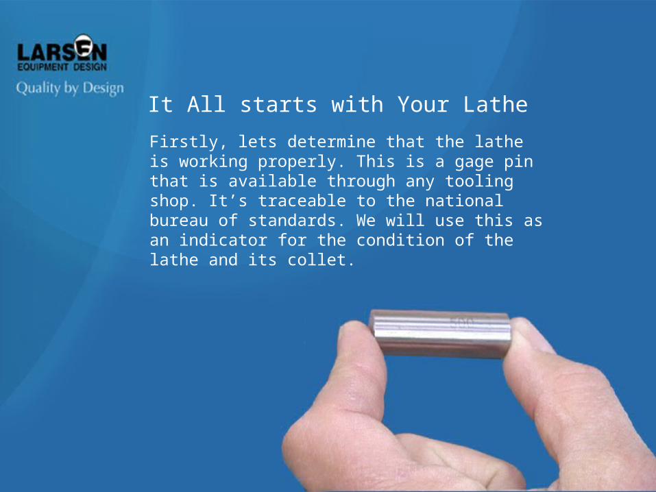
Firstly, lets determine that the lathe is working properly. This is a gage pin that is available through any tooling shop. It’s traceable to the national bureau of standards. We will use this as an indicator for the condition of the lathe and its collet.
It All starts with Your Lathe

After thoroughly cleaning
the Lathe collet, lock the gage pin in to the
depth of a normal arbor. Move the
dial indicator into place. Set it to
zero, then rotate the spindle to see
how much eccentricity exists. Anything less than five microns is acceptable. 3 microns of run-out would be equivalent to 1 ½ microns of eccentricity.
If a thorough cleaning does not correct the problem, lathe servicing would be indicated.
Checking the Lathe Collet
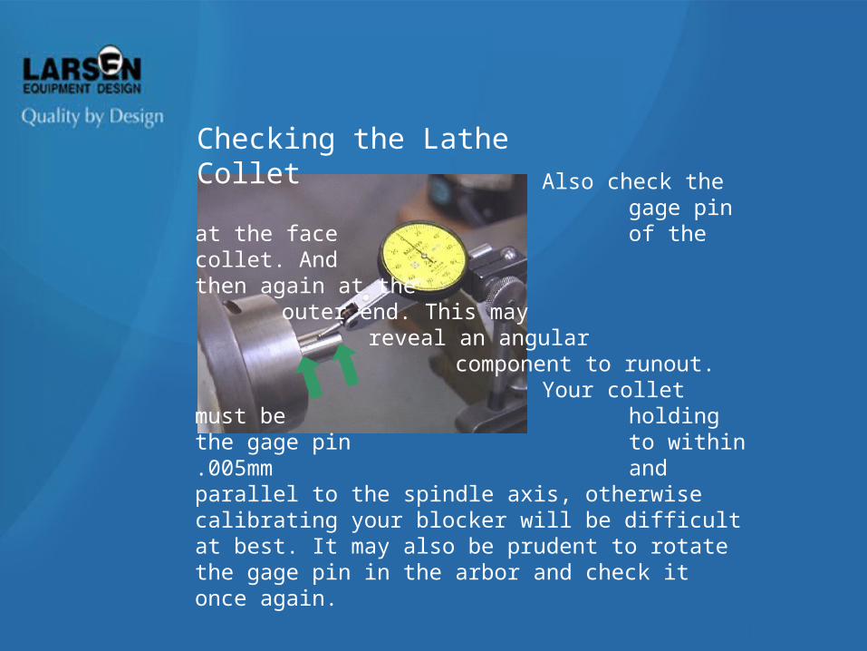
Also check the gage pin at the
face of the collet. And then again
at the outer end. This may reveal an angular component to runout. Your collet must be holding the gage pin to within .005mm and parallel to the spindle axis, otherwise calibrating your blocker will be difficult at best. It may also be prudent to rotate the gage pin in the arbor and check it once again.
Checking the Lathe Collet

Minimizing Radial Runout
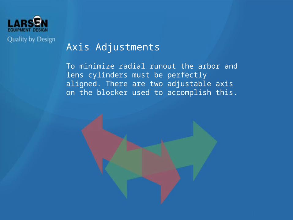
Axis Adjustments
To minimize radial runout the arbor and lens cylinders must be perfectly aligned. There are two adjustable axis on the blocker used to accomplish this.
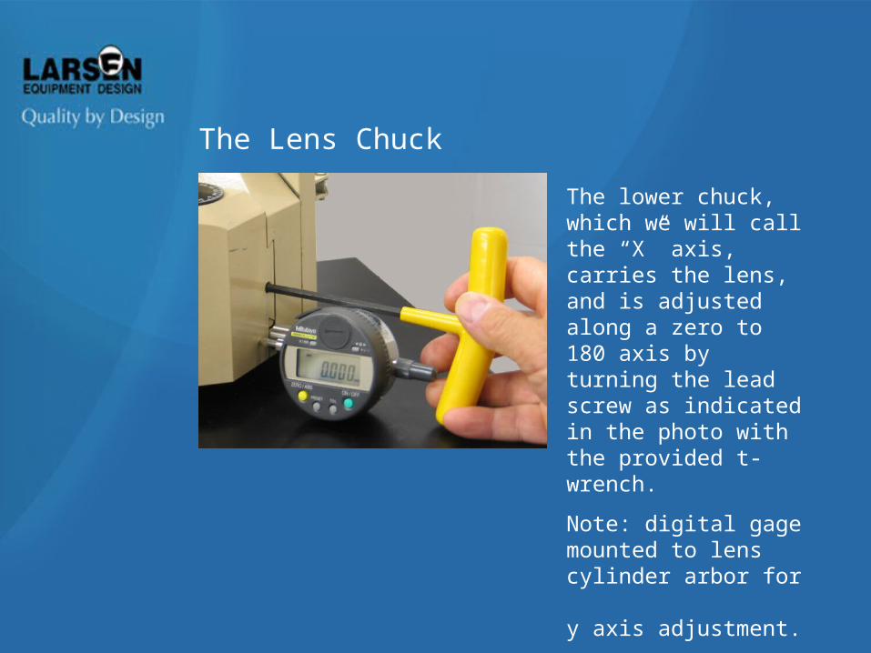
The lower chuck, which we will call the “X” axis, carries the lens, and is adjusted along a zero to 180 axis by turning the lead screw as indicated in the photo with the provided t-wrench.
Note: digital gage mounted to lens cylinder arbor for y axis adjustment.
The Lens Chuck
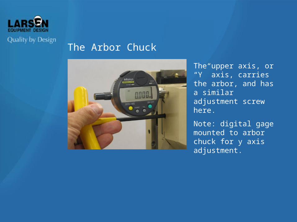
The upper axis, or “Y” axis, carries the arbor, and has a similar adjustment screw here.
Note: digital gage mounted to arbor chuck for y axis adjustment.
The Arbor Chuck
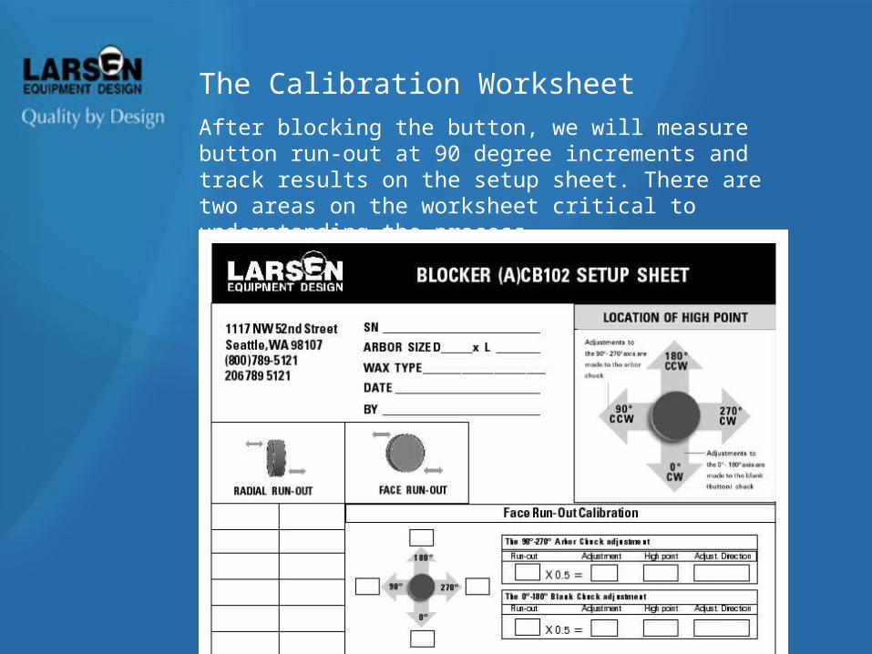
After blocking the button, we will measure button run-out at 90 degree increments and track results on the setup sheet. There are two areas on the worksheet critical to understanding the process.
The Calibration Worksheet
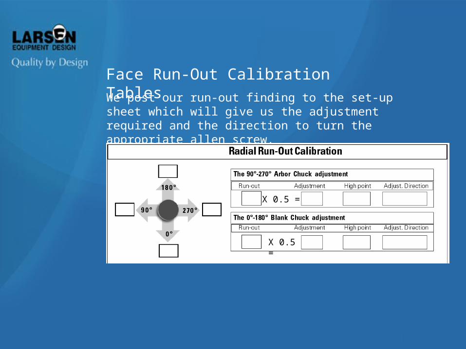
We post our run-out finding to the set-up sheet which will give us the adjustment required and the direction to turn the appropriate allen screw.
Face Run-Out Calibration Tables
X 0.5 =
X 0.5 =
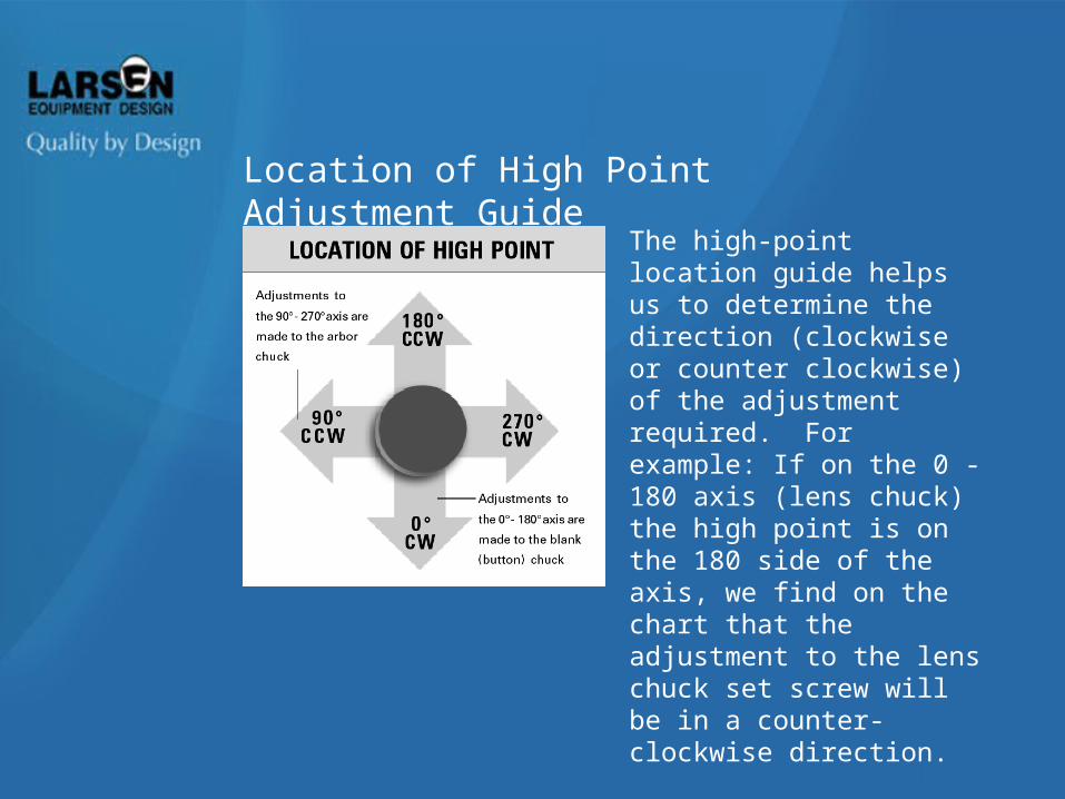
The high-point location guide helps us to determine the direction (clockwise or counter clockwise) of the adjustment required. For example: If on the 0 - 180 axis (lens chuck) the high point is on the 180 side of the axis, we find on the chart that the adjustment to the lens chuck set screw will be in a counter- clockwise direction.
Location of High Point Adjustment Guide
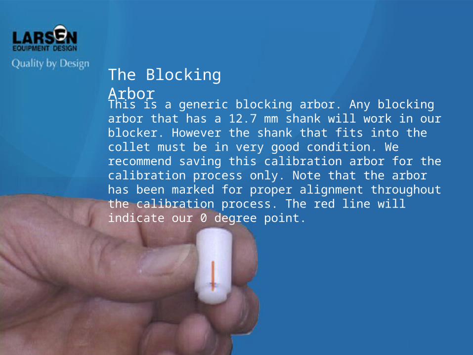
The Blocking ArborThis is a generic blocking arbor. Any blocking arbor that has a 12.7 mm shank will work in our blocker. However the shank that fits into the collet must be in very good condition. We recommend saving this calibration arbor for the calibration process only. Note that the arbor has been marked for proper alignment throughout the calibration process. The red line will indicate our 0 degree point.
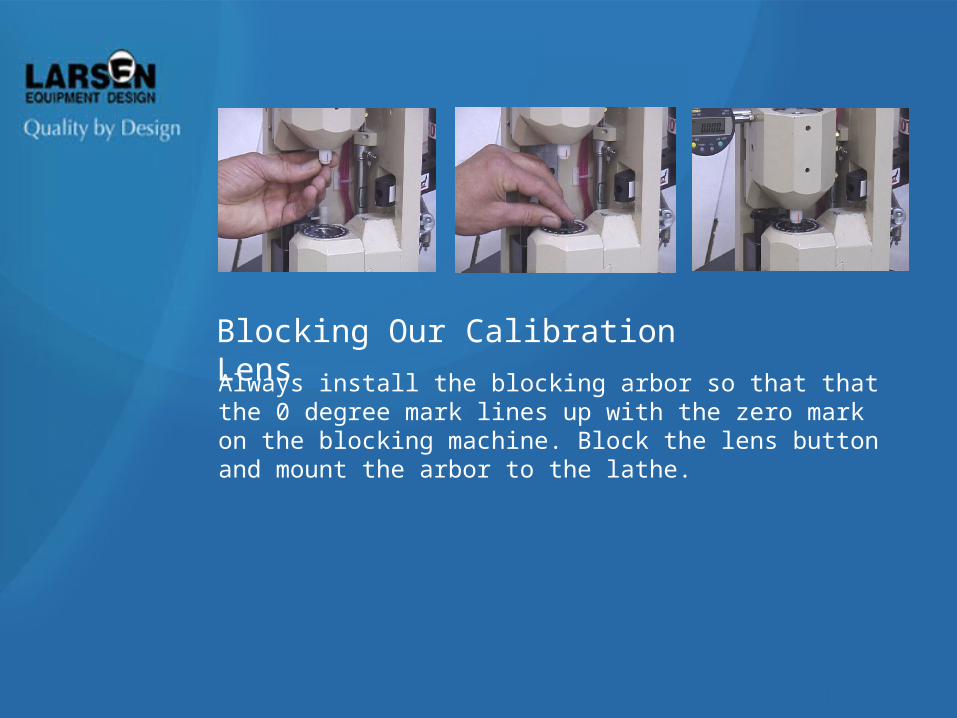
Always install the blocking arbor so that that the 0 degree mark lines up with the zero mark on the blocking machine. Block the lens button and mount the arbor to the lathe.
Blocking Our Calibration Lens

Place the blocked lens in the Lathe. Find the low spot on the lens button and set the gauge to 0. This will guarantee that all measurements are positive numbers. Measure the runout at the 0 degree mark on the arbor and place the number on the calibration sheet. Rotate the lens in 90 degree increments, counter-clockwise, recording the readings at 90, 180 and 270 degrees.
Measuring Runout
.032

Having rotated the arbor to the 90 degree point (1/4 turn from the 0 degree origin) , record the reading.
Measure Runout
.032
.028
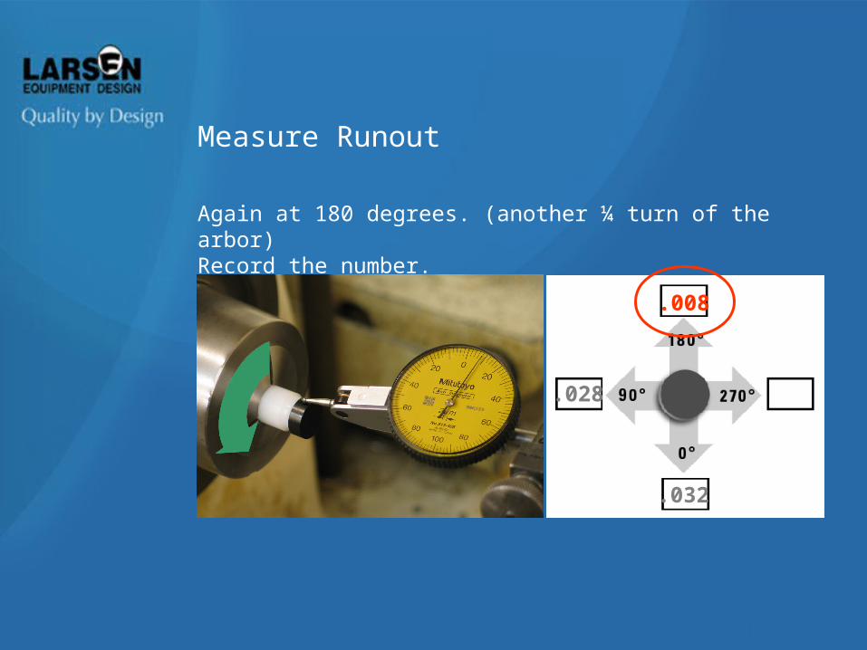
Again at 180 degrees. (another ¼ turn of the arbor) Record the number.
Measure Runout
.032
.028
.008
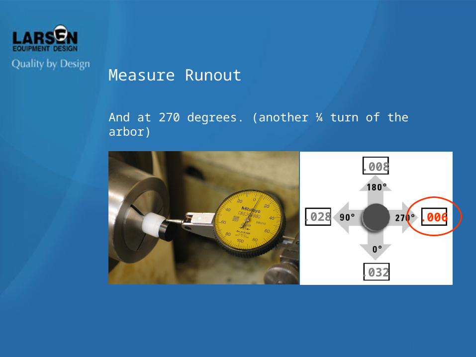
And at 270 degrees. (another ¼ turn of the arbor)
Measure Runout
.032
.028
.008
.006
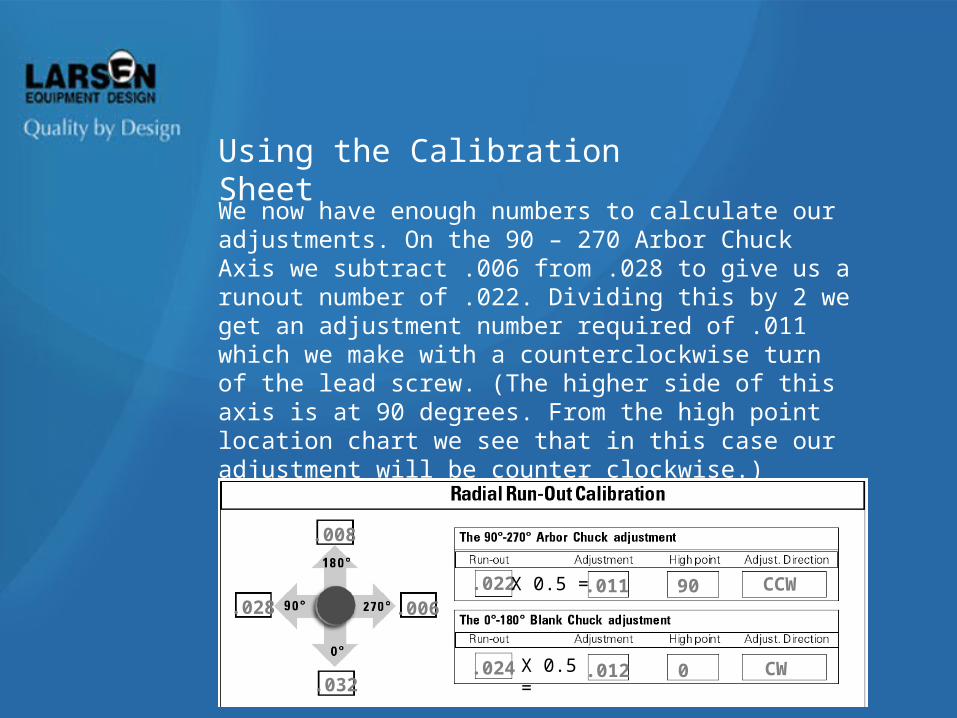
We now have enough numbers to calculate our adjustments. On the 90 – 270 Arbor Chuck Axis we subtract .006 from .028 to give us a runout number of .022. Dividing this by 2 we get an adjustment number required of .011 which we make with a counterclockwise turn of the lead screw. (The higher side of this axis is at 90 degrees. From the high point location chart we see that in this case our adjustment will be counter clockwise.)
The same process applies to the 0 - 180 axis.
Using the Calibration Sheet
.032
.028
.008
.006.022 X 0.5 =
X 0.5 =
.011 90 CCW
.024 .012 0 CW
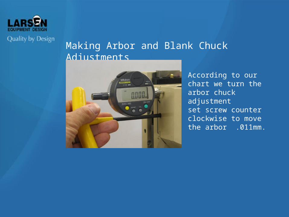
According to our chart we turn the arbor chuck adjustment set screw counter clockwise to move the arbor .011mm.
Making Arbor and Blank Chuck Adjustments
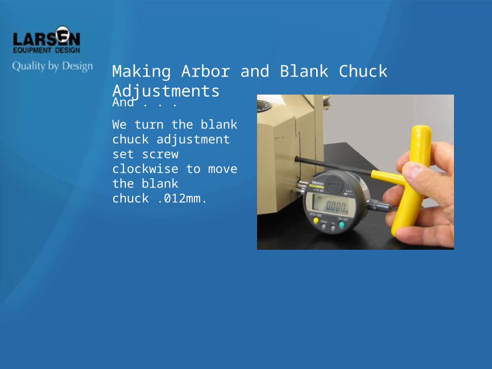
And . . .
We turn the blank chuck adjustment set screw clockwise to move the blank chuck .012mm.
Making Arbor and Blank Chuck Adjustments
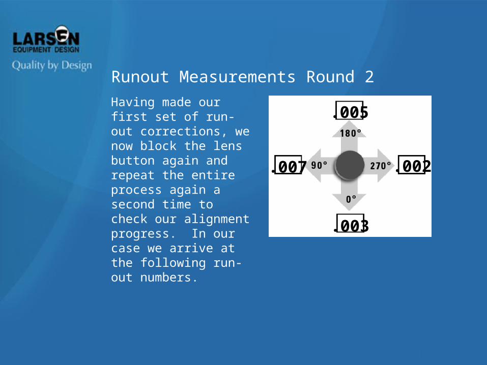
Having made our first set of run-out corrections, we now block the lens button again and repeat the entire process again a second time to check our alignment progress. In our case we arrive at the following run-out numbers.
Runout Measurements Round 2
.005
.002
.003
.007
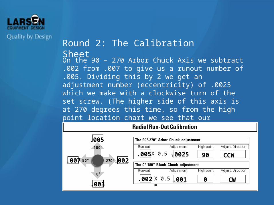
On the 90 – 270 Arbor Chuck Axis we subtract .002 from .007 to give us a runout number of .005. Dividing this by 2 we get an adjustment number (eccentricity) of .0025 which we make with a clockwise turn of the set screw. (The higher side of this axis is at 270 degrees this time, so from the high point location chart we see that our adjustment will be clockwise.) The same process applies to the 0 - 180 axis.
Round 2: The Calibration Sheet
.005
.007
.003
.002.005
.002
.0025
.001
90
0
CCW
CW
X 0.5 =
X 0.5 =
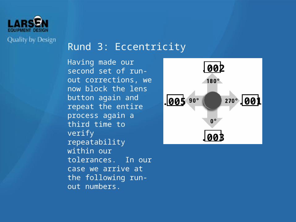
Rund 3: Eccentricity
Having made our second set of run-out corrections, we now block the lens button again and repeat the entire process again a third time to verify repeatability within our tolerances. In our case we arrive at the following run-out numbers.
.002
.001
.003
.005
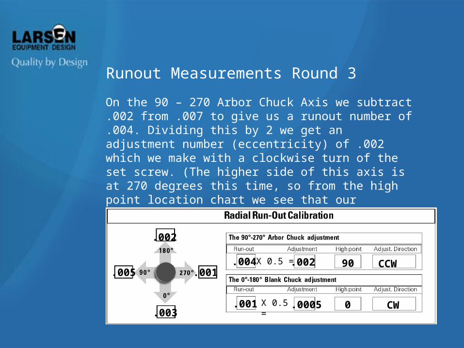
Runout Measurements Round 3
On the 90 – 270 Arbor Chuck Axis we subtract .002 from .007 to give us a runout number of .004. Dividing this by 2 we get an adjustment number (eccentricity) of .002 which we make with a clockwise turn of the set screw. (The higher side of this axis is at 270 degrees this time, so from the high point location chart we see that our adjustment will be clockwise.) The same process applies to the 0 - 180 axis.
.002
.005
.003
.001.004
.001
.002
.0005
90
0
CCW
CW
X 0.5 =
X 0.5 =
Eccentricity is half of the runout.
Calibration is not possible when the lathe cannot maintain its own tolerance of .005mm or better.
Be familiar with the calibration worksheet prior to beginning the calibration tutorial.
When calibrating a lens blank each time, be sure that the red line on the blocking arbor aligns with the 0 degree point of the arbor chuck.
Review
First culprit is usually a dirty or worn out lathe collet
Blocker collets may need cleaning
Check collet pressures. Make sure button and arbor are being held securely
Troubleshooting Prism Problems