Embed Size (px)
Citation preview

LAWHILLLAWHILLLAWHILLLAWHILL
FOR
THE LAWHILL ‘MINI’ FOLIO FINISHING SYSTEM
OPERATING INSTRUCTIONS

General Description Section 1
Operator Controls Section 2
Start Up & Normal Operating Section 3
Operating Adjustments Section 4
Fault Correction Section 5

THE LAWHILL ‘MINI’ FOLIO FINISHING SYSTEM
SECTION 1 - GENERAL DESCRIPTION The Lawhill ’MINI’ Folio Finishing System consists of two modules as shown in the photograph below. The module to the right of the operating position is the guillotine unit with the stitching unit attached, and the module on the left is the conveyor unit. The complete system is designed to convert one discrete folio size into individual booklets of a fixed size with the minimum of adjustment. The normal folio size is A4 printed with three booklets to view. This application is typical for folios produced on cut sheet laser printers processing payment booklets for weekly or monthly instalments resulting in standard 99mm booklets which are easy to mail with other folded A4 documents. The individual folio packs are loaded onto the infeed table of the guillotine unit and, as they pass long the reciprocating infeed track, a stitching unit inserts a pair of stitches into each of the three individual impressions before
the folio is finally cut into separate booklets. As the cut books emerge from the guillotine, they are continually ‘shingle’ stacked on the conveyor from where they are periodically transferred into boxes or bags. The operation of the system is continuously monitored by a programmable logic controller or PLC for short. This is housed with other control devices in a floor standing cabinet positioned beneath the conveyor. The various functions within the machine are processed by the PLC with normal operator control via a colour touch screen panel which is mounted to the rear of the guillotine module and is ideally positioned for easy access. This manual deals solely with the procedures required for operating the machine and the adjustments and fault corrections which are used during normal daily operation.
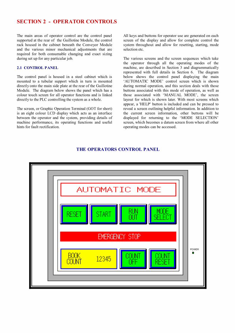
SECTION 2 - OPERATOR CONTROLS The main areas of operator control are the control panel supported at the rear of the Guillotine Module, the control rack housed in the cabinet beneath the Conveyor Module and the various minor mechanical adjustments that are required for both consumable changing and exact sizing during set up for any particular job. 2.1 CONTROL PANEL The control panel is housed in a steel cabinet which is mounted to a tubular support which in turn is mounted directly onto the main side plate at the rear of the Guillotine Module. The diagram below shows the panel which has a colour touch screen for all operator functions and is linked directly to the PLC controlling the system as a whole. The screen, or Graphic Operation Terminal (GOT for short) is an eight colour LCD display which acts as an interface between the operator and the system, providing details of machine performance, its operating functions and useful hints for fault rectification.
All keys and buttons for operator use are generated on each screen of the display and allow for complete control the system throughout and allow for resetting, starting, mode selection etc. The various screens and the screen sequences which take the operator through all the operating modes of the machine, are described in Section 3 and diagrammatically represented with full details in Section 6. The diagram below shows the control panel displaying the main ‘AUTOMATIC MODE’ control screen which is shown during normal operation, and this section deals with those buttons associated with this mode of operation, as well as those associated with ‘MANUAL MODE’, the screen layout for which is shown later. With most screens which appear, a 'HELP' button is included and can be pressed to reveal a screen outlining helpful information. In addition to the current screen information, other buttons will be displayed for returning to the ‘MODE SELECTION’ screen, which becomes a datum screen from where all other operating modes can be accessed.
POWER
THE OPERATORS CONTROL PANEL
2.1.1 Screen Operations in Automatic Mode The operator’s screen buttons that are available during normal running are displayed on the Automatic Mode screen as shown in the diagram on the previous page. As with all other screens, only those operator buttons which are displayed can be utilised while that particular screen is active. The ‘MODE SELECT’ button in the top right hand corner will stop the system and return control to the ‘MODE SELECTION’ screen where a new set of parameters will be activated through a completely new arrangement of buttons. A full description and detailed diagram of all the operator mode screens can be found in Section 4 of the Complete System Service Manual. The following control buttons are active in ‘AUTOMATIC MODE’ at all times. Pressing the ‘RESET’ button resets the system and clears all fault messages and software interlocks so that the machine is ready for normal running. When the system is reset, pressing the ‘START’ button enables all machine drives and other outputs, so that all motors start and normal running time begins. This sequence is referred to as the reset/start procedure. If a fault still prevails after the ‘RESET’ button has been pressed, the system will not start until the particular fault has been rectified and resetting has removed the particular fault from the red message bar across the centre of the screen. When a batch of work has been finished and the last folio has passed through the guillotine unit, the system will not process the last folio which remains on the infeed track immediately in front of the guillotine blade. Pressing the ‘RUNOUT’ button once, will make the infeed track cycle three times moving this last folio through the cutting process and onto the Conveyor Module. Also on this screen is a fully updating book count which indicates the books which have been completed since the last count reset. To turn the book count facility on or off, press the button to the right of the book count. This button is green when the count facility is not operating and displays the text ‘COUNT OFF’, and yellow when the count facility is active with the corresponding text display of ‘COUNT ON’. The ‘COUNT RESET’ button is to the right of the ’COUNT ON/OFF’ button and will reset the book count facility to zero. To ensure that this button is not pressed by mistake while the book count is active, its operation will only work when the count in off, ensuring that two buttons must be pressed to disable the feature. 2.1.2 Screen Fault Messages in Automatic Mode If a fault occurs in the system, the machine will stop immediately and a, normally hidden, fault information line appears on the red message bar across the centre of the screen. Each fault is indicated by a short phrase in white text as detailed by the following 12 fault messages :- INFEED NOT BACK INFEED CYCLE FAIL INFEED NOT FORWARD GUILLOTINE NOT AT TDC
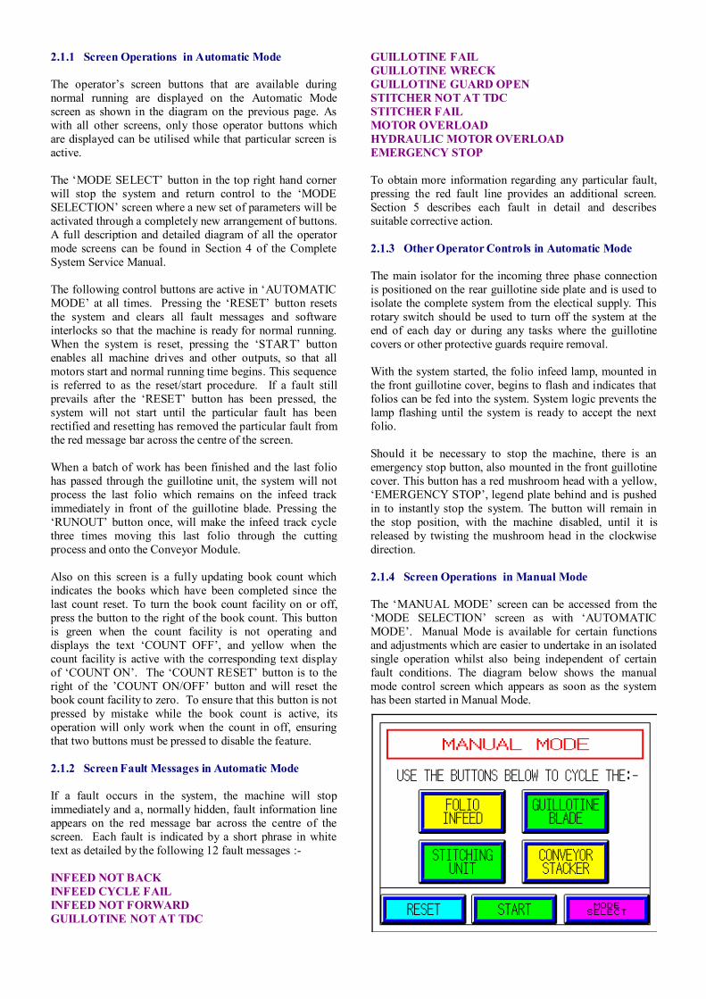
GUILLOTINE FAIL GUILLOTINE WRECK GUILLOTINE GUARD OPEN STITCHER NOT AT TDC STITCHER FAIL MOTOR OVERLOAD HYDRAULIC MOTOR OVERLOAD EMERGENCY STOP To obtain more information regarding any particular fault, pressing the red fault line provides an additional screen. Section 5 describes each fault in detail and describes suitable corrective action. 2.1.3 Other Operator Controls in Automatic Mode The main isolator for the incoming three phase connection is positioned on the rear guillotine side plate and is used to isolate the complete system from the electical supply. This rotary switch should be used to turn off the system at the end of each day or during any tasks where the guillotine covers or other protective guards require removal. With the system started, the folio infeed lamp, mounted in the front guillotine cover, begins to flash and indicates that folios can be fed into the system. System logic prevents the lamp flashing until the system is ready to accept the next folio. Should it be necessary to stop the machine, there is an emergency stop button, also mounted in the front guillotine cover. This button has a red mushroom head with a yellow, ‘EMERGENCY STOP’, legend plate behind and is pushed in to instantly stop the system. The button will remain in the stop position, with the machine disabled, until it is released by twisting the mushroom head in the clockwise direction. 2.1.4 Screen Operations in Manual Mode The ‘MANUAL MODE’ screen can be accessed from the ‘MODE SELECTION’ screen as with ‘AUTOMATIC MODE’. Manual Mode is available for certain functions and adjustments which are easier to undertake in an isolated single operation whilst also being independent of certain fault conditions. The diagram below shows the manual mode control screen which appears as soon as the system has been started in Manual Mode.

under the guillotine top cover, but is also used during the blade changing procedure. ‘STITCHING UNIT’ Pressing this button will cycle the stitching unit once and will enable a pair of stitches to be manually inserted into a section of the folio. This feature is used when the stitching unit is being prepared or tested and is necessary when the wire spool is changed or if the Hohner stitching head jams for any reason. Both of these require the wire to be re-threaded within the unit and details of this procedure can be found in Hohner Universal 48/5 S manual. After the wire has been threaded, the stitching unit must be cycled at least three times using a sample book hand held in the normal stitching position to ensure that stitches of satisfactory quality are being produced. It is essential that, whenever the stitching unit is cycled in manual, a sample book is placed in the stitching position so that loose stitches cannot ‘jam’ in the clincher plate which is mounted below the infeed track level. ‘CONVEYOR STACKER’ Pressing this button will move the conveyor belt and will continue to move all the time the button remains pressed. This function is normally used for moving cut books away from the guillotine blade area after a fault or during Manual Mode operation of the system. 2.2 RACK MODULES AND CONTROLS The photograph below shows the front of the Control Rack which is located in the floor-standing cabinet beneath the Conveyor Module and is mounted behind a steel lockable access door.
At the centre of the Manual Mode screen there are four manual buttons which can be used to cycle the main parts of the system in turn. Although most faults are ignored in manual mode, emergency stop, guillotine guard open or any motor overload will prevent the machine from starting. If this occurs, a red bar appears with the word ’FAULT’ in black text. This message overwrites the text normally at the top of the screen, but since the actual individual fault is not displayed all three areas must be examined. The four manual functions are as follows :- ‘FOLIO INFEED’ Pressing this ‘FOLIO INFEED’ button will cycle the fingers of the infeed track forwards and back once and will move a folio one position along the infeed table. This button is most commonly used to step a folio or part folio through the stitching and cutting sequence when it has been left in the blade area beneath the guillotine top cover following a fault or other stoppage. In this instance each cycle of the infeed must be followed by a guillotine blade cycle and a conveyor movement, as described later in this section, to remove each individual book in turn. Obviously, the last book in each folio will not require a cutting cycle, only a conveyor movement to bring it clear of the guillotine blade area. ‘GUILLOTINE BLADE’ Pressing this button will cycle the guillotine blade downwards to cut through a folio and then return it back up to its start position. This function is normally used following a stoppage when a folio or part folio has been left
PILZ EMERGENCY
STOP UNIT
RESET RELAY
POWER SUPPLY
PLC UNIT

The rack consists of an aluminium plate which is a standard 19" wide and 12U high, and upon which the main control modules are mounted. On a rail at the top of the rack is mounted the PLC (programmable logic controller) together with the emergency stop unit. Below this, and mounted directly to the plate, is the power supply for the complete system. Terminal rails are mounted on the reverse side of the aluminium plate and it is from these that all the machine components are hard wired. Access to the rear of the plate can only be gained by removing the cover secured to the back of the cabinet. 2.2.1 PLC Unit This unit controls and monitors the complete system through a software programme retained in the PLC’s memory and links directly to the operator interface or display screen. The unit is a Mitsubishi FX1S PLC with 16 inputs and 14 outputs. 2.1.2 Emergency Stop Unit This unit comprises of two components, the Pilz emergency stop relay and its associated reset relay. These control the safe shutdown of the system in the event of an emergency stop or the guillotine top cover being removed. The Pilz emergency stop relay enables the shutdown of all 240 VAC devices such as the single phase motors and the starter coil for the three phase hydraulic motor. The reset relay automatically resets the Pilz unit after activation as well as resetting the PLC software. 2.2.3 Power Supply Unit (5A) This module supplies 24 volt D.C. power to all PLC inputs such as switches and photocells, and all outputs such as clutches, lamps and solenoids. 2.

SECTION 3 - START-UP AND NORMAL OPERATING PROCEDURES
As already mentioned in Section 2, the main area of operator control is the colour LCD control panel and this section deals with the various screens which appear for different system functions, and the screen sequences which take the operator through all the operating modes of the machine. 3.1 START-UP PROCEDURE Switch the system on at the main machine isolator which is mounted on the rear guillotine side plate. The diagram above shows the display of the control panel with the initial screen which appears after completion of a short 'boot-up' sequence. This screen only appears at the start of the screen sequence following the switching on of the system. To proceed, press the ‘CONTINUE’ button at the bottom of this screen to display the ‘MODE SELECTION’ screen. The various modes of operation of the system can only be accessed from this screen and as such is frequently used to change from mode to mode. The layout of the ‘MODE SELECTION’ screen is shown opposite and indicates three modes of operation for the ‘MINI’ Folio Finishing System. These modes are the ‘JOB SET UP MODE’, ‘MANUAL MODE’ and ‘AUTOMATIC MODE’ and each can be selected by pressing the appropriate button.
Since direct return to this screen is essential for quick and simple operating, both the ’MANUAL MODE’ control screen and the ’AUTOMATIC MODE’ control screen display a ’MODE SELECT’ button for just this purpose. Pressing any of these three buttons will take the operator to the initial screen associated with that particular mode and these will be dealt with in turn. Pressing the ‘JOB SET UP MODE’ button will activate the ‘JOB SET UP MODE’ screen as shown at the top of the following page. This screen provides buttons for two possible set up options.
POWER

Pressing the ‘STITCHER OFF’ button effectively turns the stitching unit on and as it is being pressed it changes to green and the text will then read ‘STITCHER ON’. Pressing the same button again will change it back to the original condition i.e. yellow and ‘STITCHER OFF’. Normally this button would be green indicating that the stitching unit is turned on, but turning it off is a useful feature if a pre-stitched folio has been removed from the system following a fault and must now be cut by using the guillotine functions only. In this case, the folio will pass along the infeed track and through the cutting area without a duplicate set of stitches being applied. Pressing the ‘GUILLOTINE OFF’ button has a similar effect on the Guillotine. Again, this button would normally be green indicating to the system that the Guillotine is turned on. In the ‘OFF’ condition a folio can be processed with stitches applied but not cut into individual books. This feature might be required for samples of folios in their uncut state. With all the correct parameters now set, the system is ready to operate and pressing the ‘RETURN’ button takes the display back to the ‘MODE SELECTION’ screen. Pressing the ‘MANUAL MODE’ button changes the display to the ‘MANUAL MODE’ screen as shown below. On this screen, pressing the ‘RESET’ button, followed by the ‘START’ button, will change the display to the Manual
Mode control screen as shown below. If the central boxindicates a fault, this must be removed, and although thescreen will still change, the system will not start. The other buttons on this initial ‘MANUAL MODE’ screen allow‘RETURN’ to the ‘MODE SELECTION’ screen or additional ‘HELP’ from another screen displaying usefultext about Manual Mode operations.
From the Manual Mode control screen the four manual cycle buttons are active and are normally used for set up testing of various parts of the system prior to starting the machine in Automatic Mode. After any set up tasks in Manual Mode, the system can be started in Automatic Mode. Pressing the ‘MODE SELECT‘ button on the Manual Mode control screen, returns the display to the ‘MODE SELECTION’ screen from where Automatic Mode can be selected by pressing the ‘AUTO MODE’ button. The initial ‘AUTOMATIC MODE’ screen, shown below, provides four buttons. The ‘RETURN’ and ‘HELP’ buttons have similar functions to those on the initial ‘MANUAL MODE’ screen and pressing the ‘RESET’ button followed by the ‘Start’ button takes the display to the Automatic Mode control screen from which normal running of the system, in Automatic Mode, is continuously monitored and controlled. This screen is shown at the top of the next page and will be the most frequently used screen, as from here are displayed the normal operating parameters such as the book count and
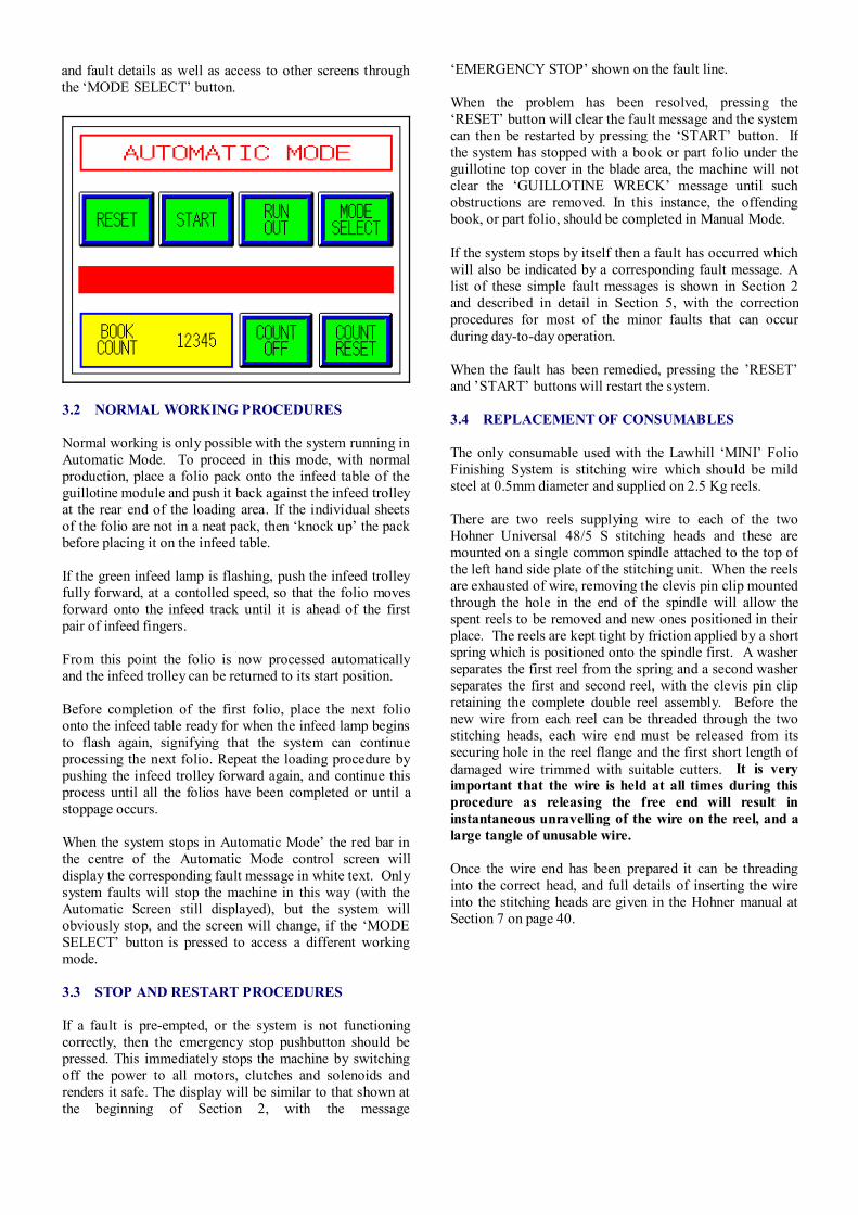
and fault details as well as access to other screens through the ‘MODE SELECT’ button.
‘EMERGENCY STOP’ shown on the fault line. When the problem has been resolved, pressing the ‘RESET’ button will clear the fault message and the system can then be restarted by pressing the ‘START’ button. If the system has stopped with a book or part folio under the guillotine top cover in the blade area, the machine will not clear the ‘GUILLOTINE WRECK’ message until such obstructions are removed. In this instance, the offending book, or part folio, should be completed in Manual Mode. If the system stops by itself then a fault has occurred which will also be indicated by a corresponding fault message. A list of these simple fault messages is shown in Section 2 and described in detail in Section 5, with the correction procedures for most of the minor faults that can occur during day-to-day operation. When the fault has been remedied, pressing the ’RESET’ and ’START’ buttons will restart the system. 3.4 REPLACEMENT OF CONSUMABLES The only consumable used with the Lawhill ‘MINI’ Folio Finishing System is stitching wire which should be mild steel at 0.5mm diameter and supplied on 2.5 Kg reels. There are two reels supplying wire to each of the two Hohner Universal 48/5 S stitching heads and these are mounted on a single common spindle attached to the top of the left hand side plate of the stitching unit. When the reels are exhausted of wire, removing the clevis pin clip mounted through the hole in the end of the spindle will allow the spent reels to be removed and new ones positioned in their place. The reels are kept tight by friction applied by a short spring which is positioned onto the spindle first. A washer separates the first reel from the spring and a second washer separates the first and second reel, with the clevis pin clip retaining the complete double reel assembly. Before the new wire from each reel can be threaded through the two stitching heads, each wire end must be released from its securing hole in the reel flange and the first short length of damaged wire trimmed with suitable cutters. It is very important that the wire is held at all times during this procedure as releasing the free end will result in instantaneous unravelling of the wire on the reel, and a large tangle of unusable wire. Once the wire end has been prepared it can be threading into the correct head, and full details of inserting the wire into the stitching heads are given in the Hohner manual at Section 7 on page 40.
3.2 NORMAL WORKING PROCEDURES Normal working is only possible with the system running in Automatic Mode. To proceed in this mode, with normal production, place a folio pack onto the infeed table of the guillotine module and push it back against the infeed trolley at the rear end of the loading area. If the individual sheets of the folio are not in a neat pack, then ‘knock up’ the pack before placing it on the infeed table. If the green infeed lamp is flashing, push the infeed trolley fully forward, at a contolled speed, so that the folio moves forward onto the infeed track until it is ahead of the first pair of infeed fingers. From this point the folio is now processed automatically and the infeed trolley can be returned to its start position. Before completion of the first folio, place the next folio onto the infeed table ready for when the infeed lamp begins to flash again, signifying that the system can continue processing the next folio. Repeat the loading procedure by pushing the infeed trolley forward again, and continue this process until all the folios have been completed or until a stoppage occurs. When the system stops in Automatic Mode’ the red bar in the centre of the Automatic Mode control screen will display the corresponding fault message in white text. Only system faults will stop the machine in this way (with the Automatic Screen still displayed), but the system will obviously stop, and the screen will change, if the ‘MODE SELECT’ button is pressed to access a different working mode. 3.3 STOP AND RESTART PROCEDURES If a fault is pre-empted, or the system is not functioning correctly, then the emergency stop pushbutton should be pressed. This immediately stops the machine by switching off the power to all motors, clutches and solenoids and renders it safe. The display will be similar to that shown at the beginning of Section 2, with the message

SECTION 4 - OPERATING ADJUSTMENTS
simple check list when making thickness change adjustments. The three labels, shown below are positioned as follows : Labels 1 and 2 are attached either side of the guillotine top cover, and Label 3 to the stitching unit covers which covers the internal components of the stitching unit.
LABEL 3
4.1 SUMMARY OF ADJUSTMENTS The mechanical adjustments which are required to be made to the system, when changing from one book thickness to another, are summarised on three labels positioned at strategic parts of the machine for the operator to use as a
STITCHING UNIT ADJUSTMENTS 1) ADJUST THE STITCHING UNIT TO THE
CORRECT BOOK THICKNESS SETTING BY SIZING THE THICKNESS OF BOOK TO THE GAP IN THE SETTING GAUGE AT THE LEFT HAND SIDE OF EACH UNIT
1) ADJUST WIRE LENGTH AND WIRE POSITION
TO SUIT EACH PARTICULAR BOOK THICKNESS
LABEL 2
LABEL 1
INFEED TRACK ADJUSTMENTS 1) SET THE ADJUSTABLE SIDE GUIDE TO SUIT THE WIDTH OF FOLIOS YOU ARE PROCESSING 2) ADJUST THE HOLD DOWN STRIPS FOR THE CORRECT TENSION TO SUIT THE THICKNESS OF FOLIOS YOU ARE PROCESSING
CONVEYOR ADJUSTMENTS 1) ADJUST THE CONVEYOR SPEED CONTROL TO PROVIDE
CORRECT SHINGLE STACKING 2) ADJUST THE HOLD DOWN WHEELS FOR CORRECT SHINGLE
STACKING IF REQUIRED
4.2 GUILLOTINE ADJUSTMENTS As already stated, the adjustments of every module in the system can be divided into cheque book width, cheque book depth and cheque book thickness and 4.1.0 above summarises these adjustments. The following sub-sections describe these adjustments in more detail. 4.2.1 Book Width Adjustments The guillotine module is normally the start of the book making process, with the folio set being hand fed onto the guillotine infeed table. The rear vertical face of this table is the datum edge for the book folio and as such is a fixed guide, while the front vertical face is an adjustable guide which can be readily moved to accomodate small variations in the widths of folios. This is a necessary adjustment as the width of standard A4 paper has a nominal tolerance of +/- 2 mm giving a 4 mm possible variation from supplier to supplier. Initially, the clamping handles which hold the adjustable guide in position, must be released and the guide moved inwards or outwards so that it is parallel to the front edge of the test folio with approximately 1 mm of clearance. The two clamping handles are now tightened ready for production. 4.2.2 Book Thickness Adjustments Mounted at three positions along the guillotine infeed table are ‘hold-down’ assemblies which can be adjusted so that constant holding pressure may be applied to the folios of all thicknesses. The basic principle of these ‘hold-down’ assemblies applies for each station and is an important design feature of the system. The correct setting of the ‘hold-down’ strips cannot be quantified easily, as booklet thickness, quality of paper, machine station and machine speed influence their effect. However, the normal skills and experience obtained from operating the system are sufficient in most instances for gauging the pressures that are required. The infeed table has three such ‘hold-down’ assemblies each with two ‘hold-down’ strips which are mounted on cross bars, anchored by support blocks, which in turn are attached to the front of the infeed table. The rotary movement of these bars provides the variation in hold-down pressure and are adjusted by releasing the small clamping handle in the support block. Using the lobe knob provided, the bar may be rotated by hand, until the required pressure under the strips is attained. At this point, the clamping handles may be re-locked to maintain the bar in the chosen position. 4.3 STITCHING HEAD ADJUSTMENTS To assist with the various adjustments of the stitching unit, the Hohner Universal 48/5 S manual should be available for reference. The important parts of this manual which should be read carefully are as follows :-
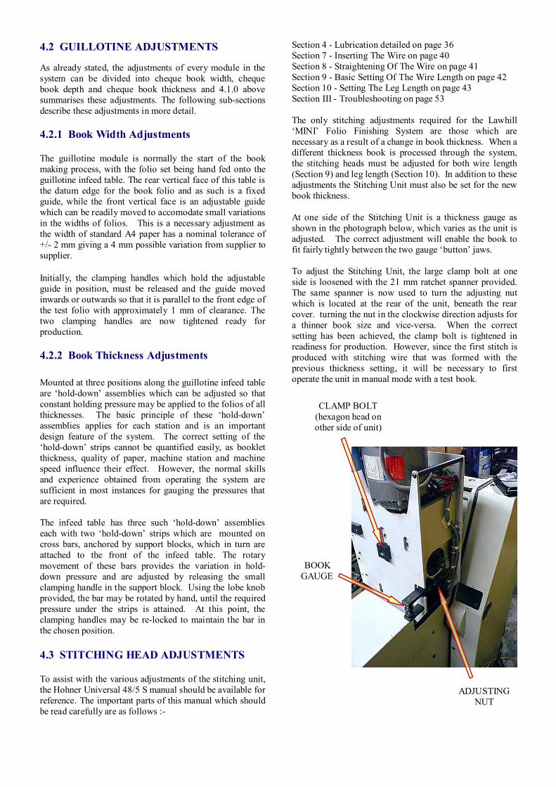
Section 4 - Lubrication detailed on page 36 Section 7 - Inserting The Wire on page 40 Section 8 - Straightening Of The Wire on page 41 Section 9 - Basic Setting Of The Wire Length on page 42 Section 10 - Setting The Leg Length on page 43 Section III - Troubleshooting on page 53 The only stitching adjustments required for the Lawhill ‘MINI’ Folio Finishing System are those which are necessary as a result of a change in book thickness. When a different thickness book is processed through the system, the stitching heads must be adjusted for both wire length (Section 9) and leg length (Section 10). In addition to these adjustments the Stitching Unit must also be set for the new book thickness. At one side of the Stitching Unit is a thickness gauge as shown in the photograph below, which varies as the unit is adjusted. The correct adjustment will enable the book to fit fairly tightly between the two gauge ‘button’ jaws. To adjust the Stitching Unit, the large clamp bolt at one side is loosened with the 21 mm ratchet spanner provided. The same spanner is now used to turn the adjusting nut which is located at the rear of the unit, beneath the rear cover. turning the nut in the clockwise direction adjusts for a thinner book size and vice-versa. When the correct setting has been achieved, the clamp bolt is tightened in readiness for production. However, since the first stitch is produced with stitching wire that was formed with the previous thickness setting, it will be necessary to first operate the unit in manual mode with a test book.
CLAMP BOLT (hexagon head on other side of unit)
BOOK GAUGE
ADJUSTING NUT

SECTION 5 - FAULT CORRECTION
5.1 GENERAL In normal automatic operation the ‘AUTOMATIC MODE’ control screen will appear, without displaying any fault message. If a machine detectable fault occurs, the system will immediately stop as if one of the emergency stop buttons had been pressed. In fact all faults detected by the machine will interrupt the emergency stop circuitry, halting the supply to all the outputs such as motors, clutches, heaters and the like. As the machine stops, a fault message, corresponding to the particular cause of stoppage, will appear as white text within the red bar across the centre of the screen. Most of the fault messages are of obvious meaning, but a detailed description of the fault, with a suitable correction procedure can be obtained by pressing the red bar containing the message. Pressing this key provides a dedicated screen for the particular fault and provides explanatory text describibg suitable corrective action. Pressing the ‘RETURN’ button at the bottom of the help screen will re-activate the normal ‘AUTOMATIC MODE’ control screen and here, once the fault has been successfully cleared, pressing the ‘RESET’ button will clear the red bar and allow the system to be restarted by pressing the ‘START’ button. The faults which are monitored by the system are described below and are described in the order in which they might most commonly occur. 5.2 GUILLOTINE FAULTS ‘EMERGENCY STOP’ This message indicates that the emergency stop switch has been pressed and this switch, is mounted in the front cover of the Guillotine Module. The switch is labelled ‘EMERGENCY STOP’ and is the ‘PUSH ON / TWIST OFF’ type, with a large red mushroom head. If the switch has been pressed it must be twisted clockwise to release the switching mechanism. With the switch released the machine can be restarted using the reset/start procedure. The normal use of this switch is for operator control of the book making process, or for switching the machine ‘OFF’ while minor operator adjustments are made. ‘GUILLOTINE GUARD OPEN’ There is one guard switch which is actuated by the top cover of the guillotine unit. This cover is over the blade area giving protection from the most potentially dangerous part of the machine. This switch is normally closed and opens the guard switch circuit if the cover is removed or dislodged in any way. As the switch operates the fault message ‘GUARD OPEN’ appears on the screen and the system stops. Normally the cause is a guard which has not been tightened down properly or that the switch is defective. If the cause of the fault cannot be readily found, an engineer should investigate the problem. If the guard is removed to investigate the fault, the machine MUST be switched off at the main isolator first and must be repositioned and secured before the system is switched
‘GUILLOTINE NOT AT T.D.C.’ This message indicates that the guillotine blade is not in its top dead centre position after the guillotine’s hydraulic system has been energised during the normal machine cycle. This situation can occur if either the hydraulic motor, the hydraulic valve or the top dead centre photocell (Opto 7) are defective. If the fault does not respond to the reset/start procedure, then the fault is probably within the hydraulic system and an engineer should be contacted immediately to rectify the problem. ‘GUILLOTINE WRECK’ This message normally indicates that a book is present somewhere in the guillotine blade area between the Opto 5 and Opto 6 photocells when that area should be clear. This situation will normally arise when an emergency stop or other such fault has stopped the machine and a book, part of the folio or all of the folio is halted prior to the completion of the guillotine cutting process. Since the normal cycle has now been interrupted, the reset/start procedure will only re-start the machine when the, folio or part folio has been removed and the ‘GUILLOTINE WRECK’ message eliminated. To achieve this, the ‘MODE SELECT’ button must be pressed to return to the ‘MODE SELECTION’ screen where the system can be re-activated in ‘MANUAL MODE’. The offending books can now be progressed onto the Conveyor Module by use of the ‘FOLIO INFEED’, ‘GUILLOTINE BLADE’ and ‘CONVEYOR STACKER’ buttons on the ‘MANUAL MODE’ control screen. When all remnants of the folio have been fully removed from the guillotine blade area, ‘AUTOMATIC MODE’ can now be re-selected, via the ‘MODE SELECTION’ screen, to continue book production. ‘GUILLOTINE FAIL’ This message can occur for one of two reasons. The first is when the guillotine down valve has been activated at the start of the cutting cycle, but the top dead centre (TDC) photocell is still covered or ‘ON’ indicating that the guillotine blade has not moved. The second is when the Guillotine down valve has been activated, but the bottom dead centre (BDC) photocell has not been activated within a predetermined time. In both cases an engineer should investigate the problem immediately. ‘INFEED TRACK NOT BACK’ During one complete cycle of the reciprocating infeed track, the forward and back positions are indicated by switches. In the back position the track begins and ends its movement, while fully forward it positions the folio along the infeed track. If the messages ‘INFEED TRACK NOT BACK’ is displayed as a machine fault, then the back switch is not operating correctly and will prevent further cycling of the infeed track. Adjustment of the switch or
replacement should be carried out by an engineer. ‘INFEED NOT FORWARD’ This fault occurs when the infeed track has commenced a cycle and not registered its fully forward motion by activating the track forward switch. If this fault message appears an engineer should investigate the problem before the system is restarted in ‘AUTOMATIC MODE’. ‘INFEED CYCLE FAIL’ This fault occurs when the infeed track has commenced a cycle and has passed through the fully forward position, but has not returned to the back switch within a predetermined time. If this fault message appears an engineer should investigate the problem before the system is restarted in ‘AUTOMATIC MODE’. ‘MOTOR OVERLOAD’ The message ‘MOTOR OVERLOAD’ indicates that one of the two single phase motors in the system has been overloaded and the contact breaker for that particular motor has ‘cut out’. Both of the breakers are located on the upper terminal rail at the rear of the control rack and are not accessible to the operator. The two motors are the INFEED MOTOR and the STITCHING UNIT MOTOR. An overload fault is normally caused by overheating due to the motor drawing too much current and usually occurs if the particular drive components have been damaged or have ‘jammed’, but in any event an engineer should investigate the problem immediately. ‘HYDRAULIC MOTOR OVERLOAD’ The message ‘HYDRAULIC MOTOR OVERLOAD’ indicates that a problem has occurred with the hydraulic motor which drives the guillotine blade. The overload trip which activates this fault is normally preset at manufacture to the correct working current of the motor. This can be exceeded for a number of reasons, such as a drop in supply voltage, and pushing the stop and start buttons on the guillotine motor isolator, mounted at the rear of the guillotine unit, will normally rectify the fault. The machine can then be re-started using the reset/start procedure. If the machine cannot be re-started successfully then the fault must be rectified by an engineer. 5.3 STITCHING UNIT FAULTS ‘STITCHER NOT AT TDC’ The ‘STITCHER NOT AT TDC’ fault message indicates that the top dead centre switch on the stitching unit has not operated at the end of the stitching cycle. This switch protects the system by stopping the machine should either stitching head ‘jam’ at some point during the stitching cycle. If this fault occurs because of obvious damage to the stitching head or the drive system, then repair must be carried out by an engineer. If the stitching unit appears to be undamaged, the actual switch may be at fault or require
adjustment. Because this switch is mounted beneath the stitching unit cover, replacement or adjustment should also be carried out by an engineer. ‘STITCHER FAIL’ The ‘STITCHER FAIL’ fault message indicates that the two stitching heads are still at the top dead centre position, as indicated by a closed top dead centre switch on the stitching unit, after the stitcher clutch has been activated in normal Automatic Mode operation. This would suggest that the stitching unit mechanism has ‘jammed’ in some way, or that the TDC switch is faulty. If this fault occurs because of obvious damage to the stitching head or the drive system, then repair must be carried out by an engineer.