Embed Size (px)
Citation preview

NASA Contractor Report 196694
The Lift-Fan Aircraft: LessonsLearned
Wallace H. Deckert
Ames Research Center
Moffett Field, CA 94035-1000
Prepared forAmes Research CenterCONTRACT NAS2-5364D
March 1995.
National Aeronautics and
Space Administration
Ames Research CenterMoffett Field, California 94035-1000
https://ntrs.nasa.gov/search.jsp?R=19950020723 2018-06-08T18:37:54+00:00Z


CONTENTS
Introduction ...........................................................................................................................
Summary of the Technical Presentations by
Wallace H. Deckert, NASA Ames retiree. Missions, lift-fan aircraft design
studies, contractual full-scale research, and flight test of the Avrocar .................................
David H. Hickey, NASA Ames retiree and Jerry V. Kirk, NASA Ames staff.
Lift-fan induced airframe aerodynamics, cross-flows and inlets, large versus
small-scale results, thrust vectoring, and acoustics ...............................................................
Woodrow L. Cook, NASA Ames retiree. Flight characteristics of designs and
real aircraft, related wind tunnel investigations, and recent experience with
a lift-fan aircraft development project ..................................................................................
James A. Franklin, NASA Ames staff. Stability and control, including
computer, fixed-based, and moving-base piloted simulations; and lift-fan
related results from VSRA aircraft flight investigations ......................................................
Ronald M. Gerdes, NASA Ames retiree. Pilot's perspective.
XV-5B and other flight activities, and piloted moving-base simulations
at NASA and elsewhere ........................................................................................................
References .............................................................................................................................
Page
ix
9
23
37
51
58
PRECEDING PAGE BLANK NOT FILMED iii


Acknowledgements
To Mr. John Burks of NASA Ames for creating this activity as delineated in the
section Abstract.
To Mr. Clark White of NASA Ames, the contracting Officer's Technical
Representative, who provided outstanding "real time" leadership.
To hundreds whose names are not in this report, but if such acknowledgements
were possible, should be.
PRECEDING PAGE BLANK NO1" FILMED


Abstract
This report summarizes the highlights and results of a workshop held at NASA Ames Research
Center in October 1992. The objective of the workshop was a thorough review of the lessons learned
from past research on lift fans, and lift-fan aircraft, models, designs, and components. The scope
included conceptual design studies, wind tunnel investigations, propulsion system components,
piloted simulation, flight of aircraft such as the SV-5A and SV-5B and a recent lift-fan aircraft
development project. The report includes a brief summary of five technical presentations that
addressed the subject The Lift-Fan Aircraft: Lessons Learned.
PRECEDING PAGE BLANK NOT FILME.D vii
I


Introduction
In 1992 Mr. John Burks of the Aircraft Technology Division,
NASA Ames Research Center, initiated an activity to review the lessons
learned from past lift-fan aircraft research investigations. The time period was
1956 to 1992. The scope of work included NASA retirees and present staff
authoring five written technical papers, one oral presentation, and the conduct
of a Workshop on October 28 & 29, 1992. The five written papers are
summarized in this report. The oral presentation by Laurence Gertsma of
NASA Lewis is not included as reference material was not available.
The objective was a thorough review of the lessons learned from past
research on lift fans, and lift-fan aircraft, models, designs, and components.
Scope included conceptual design studies, wind tunnel investigations,
propulsion system components, piloted simulations, flight of aircraft such asthe XV-5B, and a recent lift-fan aircraft development project. One hope is that
this effort will help foster the continued advancement of light-fan aircraft
technology, and do so "without reinventing the wheel".
The first lift-fan aircraft research investigation in the nation featured a "lift
fan" in a two-dimensional wing. This research, by Mr. David H. Hickey of
NACA Ames, was initiated in 1956. Since then, NACA, NASA, their
contractors and others have authored hundreds of publications on lift-fan
aircraft technology.
Most of the lift-fan aircraft research was applicable to subsonic aircraft. For
supersonic lift-fan aircraft, takeoff, landing, conversion to and from powered-lift
flight, and some mission legs are at subsonic speeds. This fact, and because
some research was generic, makes some subsonic research applicable to
supersonic aircraft. Some research was specific to supersonic aircraft.
Lift-fan aircraft research was applicable to all categories of powered-lift
including those known by the acronyms STOL, VTOL, V/STOL, and STOVL.
Too many understand these acronyms superficially. See Reference 1, Appendix
I for definition and design implications of these acronyms.
Lift-fan aircraft are competitive throughout the powered-lift spectrum;
STOL, VTOL, V/STOL, and STOVL. They are applicable to supersonic and
subsonic, civil and military, fighter and transport, and personal aircraft.
The applicability of lift-fan aircraft is partly because vertical flight often
requires dynamic vertical flight as opposed to sustained steady-state hovering
flight while in the vertical flight mode. Design and operational considerations
differ for dynamic vertical flight and sustained hovering flight. Differences
occur with respect to fuel usage, reingestion, FOD, visibility, noise,
PRECEDING PAGE BLANK NOT F_L_/FEr)
ix
f'/_,:_Eq 'I\\........i>.'_C__'_'_.'-_'I"j

nonproductive time, ground-effect-induced performance changes and attitude
upsets, detectability, and site preparation. A lesson learned was that differences
favor dynamic vertical flight, often by a wide margin.
X

Summary of the Technical Paper by Deckert, Reference 1
Mission Applications
Though promising for certain missions that require sus-
tained hovering, lift-fan aircraft are most promising for
missions that require dynamic vertical flight. Example mis-
sions that require hover are those for which time is of the
essence and radius of action is long, such as oceanwide
search and rescue. Though lift-fan aircraft could be
utilized for todays missions, they are better characterized
as yielding new civil opportunities and new military
strategies. Many examples of both are presented.
A view that is too limited is that lift-fan aircraft
are promising because of their takeoff and landing capabil-
ity such as STOVL or V/STOL. A lesson learned was lift-fan
aircraft are promising for many reasons, such as (i) short
or vertical takeoff and landing, (2) near-terminal departure
and approach patterns, (3) up-and-away flight performance,
(4) maneuverability, (5) design tradeoffs such as wings
designed for cruise and not compromised by takeoff and
landing, (5) advantages from ground facilities such as ski-
jumps, (6) total system savings such as not requiring the
aircraft carrier to turn into the wind, and (7) much more.
Lift-Fan Aircraft Design Studies
The section begins with the first NASA lift-fan air-
craft design, an in-house effort published in 1964. A
lesson learned was the knowledge gained by including refer-
ence aircraft on each side of the powered-lift spectrum
compared to the aircraft under study. If design is about
STOVL, then the scope should include designs to the same
mission (as much as possible) of one V/STOL and one STOL.
The second design effort was contractual studies in the
mid 1960s, figure I. Lessons learned included:
* The importance of preparations. Prior to go-ahead,
NASA spent months on design goals and criteria.
* The weight advantage by using burning reaction control
nozzles, and how to select their design point so that only
rarely is the burning feature ever initiated.
* "A red flag of warning" that pure fan-in-wings may not
be competitive with other lift-fan configurations.
* Advantage in gust sensitivity, due to the lift-fan con-
cepts high wing loading and low-aspect ratio and swept wing.
* Caution required before concluding that lift-fan air-
craft are noisier or quieter than other concepts.* That lift-fan aircraft have "time on their side", be-
cause the impact of advancing technology favors the concept.
* Sensitivity of short-haul economics to nonproductive

time, and how the lift-fan deceleration capability can be
used to minimize nonproductive time.
* Need to periodically review the "lift-fan family-of-air-
craft concept". If a "second best" lift-fan STOL uses much
of the same propulsion as its vertical flight counterpart,
then the STOL will not be second-best for the total system.
Another study was on V/STOL lift-fan research trans-
ports, figure 2. One lesson learned concerned design goalsfor research aircraft, which are different than those for
operational aircraft. Many design goals for research air-
craft are less demanding . A lesson learned was to give con-
sideration to the opposite case. That is, to specify which
of the design goals for research aircraft should be tougher
than for the operational aircraft. Higher control power
during low-speed flight and other examples are presented.
A study in the 1970s was on V/STOL short-haul tran-
sports, figure 3. Aircraft were designed for either engine
or lift-fan failure. Lessons learned included:
* Not to assume about V/STOL performance. A case is pre-
sented in which VTOL had greater range than I000 ft STOL.
* That maximum ground roll acceleration does not occur
when thrust is pointed straight down the runway.
* For aircraft with equal number of engines, that V/STOL
has higher dispatch reliability than CTOL.
* Civil and military V/STOLs (unlike VTOLs and STOLs)
have much different design points.
* Unlike for CTOLs, the best V/STOL design is one that is
non-optimum for the primary mission.
* Implications of the above for a STOVL program.
In the 1970s NASA studied military STOVL aircraft for
Vertical-Onboard-Delivery, figure 4. Lessons learned:
* The compatibility between military and civil lift fans.
* Initial understanding of two-stage lift fans.
* The quad entry scroll and its possible application to a
STOVL supersonic fighter.
Next were studies of Navy multimission STOVL aircraft,
figure 5. Lessons learned included:
* The design flexibility available if lift fans are
interconnected by gas duct or mechanically. Flexibility is
more important for multimission than for single mission de-
sign. The same basic multimission in this study had 2 or 3
gas generators as a function of the specific mission.
* The importance of gyroscopic coupling. Even after
minimizing with opposite rotation of parts, one design was
limited by gyroscopics in nacelle incidence rate and air-
craft roll rate. Should a STOVL design with one 2-stage fan-
in-fuselage have counterrotating stages?
The final design study presented in the paper is on
military multimission research and technology aircraft,
2

figure 6. Lessons learned included:
* Understanding of the Scroll-in-Scroll concept, and im-
portance of continuing advancement of scroll technology.
* The inherent safety and other features of a low-speed
control system that uses both Energy Transfer Control (ETC)
and Thrust Reduction Modulation (TRM).
Design Integration
Presented are full-scale experimental investigations on
manifolding of gas generators, interconnect ducting, and the
Energy Transfer Control system. Lessons learned included:
* Manifolded gas generators, figure 7, are insensitive to
transients, even those due to gas generator failure. The
time that transient lift loss can be tolerated in flight
will dictate design and valve closure rates rather than gas
generator or other propulsion component sensitivities.
* Full-scale metal and composite interconnect duct seg-
ments were promising. The semi-flexible composite ducts
offered advantages of weight, both by weight per length and
by elimination of heavy connecting elements such as bellows.
* An Energy Transfer Control system, figure 8. The paper
lists i0 lift-fan aircraft low-speed control systems and
presents the promising results from full-scale experimental
investigations of Energy Transfer Control.
The Avrocar Flight Evaluations
The author was the USAF project manager of flight
evaluations of the Avrocar, figure 9. Lessons learned were:
* The Avrocar was flown first; put in NASA's full-scale
tunnel second. That sequence of events was backwards.
* The importance of the performance of gas ducts.
* The unacceptability of pure thrust spoilage control.
* Huge changes from small changes of ground height.
* The asymmetry exhibited by symmetric-looking aircraft.
A STOVL fan-on-fuselage-centerline is not symmetrical.
* Gyroscopics, though typically adverse, can be harnessed
and used favorably, as on the Avrocar for stability.
* The many favorable effects from operationally taking VL
to mean almost Vertical, not purely Vertical, Landing.
* The toughness of lift fans, as exemplified by this very
first flightworthy lift fan.
* Importance of an acceptable cockpit environment.
Concluding Remarks stress need for lift-fan technology
aircraft. Such projects exercise the too-inactive contrac-
tual design teams; augment R & T base; include fabrication,
qualifications, flight technology demonstration, and long-
term flight research; and for mature technology like the
lift fan, are the mechanism that enables application.
3

34.5'
/- Estimated C.G. locationat D.G.W.
Fuel in wings /"+'" '///_
\ / /-//,,- MAX 195'
I _ .... -"!-'- - +_--l------_,+_\ APU':,_ \ i I ""I +_., ., , -_ +: \ ....... \ .........
Airstairs __'+ +Cargo I i Cargo \ Airstairs -_- , 31.4' -_- + (under floor)
1= 8zs' ---J
Figure l. Boeing 60-passenger VTOL lift-fan aircraft design.
33.5
L_
4
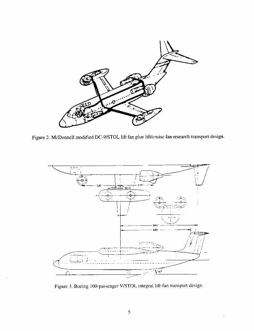
Figure 2. McDonnell modified DC-9/STOL lift fan plus lift/cruise fan research transport design.
71 ':3 -/--_ '5°
Figure 3. Boeing 100-passenger V/STOL integral lift-fan transport design.

0.467 SCALE
Jl01 TECH GAS
GENERATOR
I SOLATI ONVALVE
LIGHTWEIGHT CROSS DUCTING
CONTROL VALVES
1.5 FPR 2-STAGE
VTO DESIGN FANS
QUAD ENTRIES
INTEGRATED SINGLE"CONTROL VALVES SWIVEL NOZZLES
Figure 4. Rockwell STOVL design for Navy Vertical-Onboard-Delivery.
Clutch
Cross shaft
T-box
- Accessories
Reduction gear
Lift/cruise fan
Lift fan
Drive shaft Shaft
Bevel gears (typ)
Figure 5. Isometric of Boeing Navy multimission design
6

ETaC
VALVES
59 IN. TURBOTIP FAN
3rd ENGINE
DIVERTER
VALVE
J-97 GAS
GENERATOR _ HOOD
LIFT FAN
INL
DUCTING
_'- LIFT FAN
VECTORING SYSTEM
GAS GENERATOR
INLET
Figure 6. McDonnell modified T-39 RTA V/STOL aircraft design.
YJ97
Figure 7. Full-scale investigation of characteristics of manifolded Y J-97 gas generators.

Isolation Valve No. 2"_
t Shutoff Valve J m
t--lsolation Valve No. I
LL-Fan NO. 1 ETC Valves No. 1
Figure 8. General arrangement of a paired Energy Transfer Control system.
• "'" :'" ..... "?,'-3P .....
9
Figure 9. USA VZ-9AV/Avro Aircraft Limited Avrocar hovering 1 foot above concrete.
8ORIGINAL PAGE IS
OF POOR QUALITY

Summary of Technical Paper by Hickey and Kirk, Reference 2
Experimental Modelling
For CTOLs viscous and scale effects must be consider-
ed. For STOVLs it is further complicated by the necessity
to model propulsion and free stream mixing and entrainment.
This impacts acceptability of powerplant simulation.
Figure i0 shows viscous effects for tilt duct lip flow
separation. Though the small-scale duct was of reasonable
size (17 in dia), the inner lip stalled 35 deg before the
full-scale. Outer lip differences were greater. Another
result was that i/6 scale cascade vanes had a major loss in
turning efficiency compared to the full-scale cascade.
In 1960 NASA Ames studied the first large-scale model
with a fan (5.2 ft dia) mounted in the fuselage. Primary
differences between this model and a I/9 small-scale model
were in the fan blade geometry itself and the stator. Fig-
ure ii, lift variation with forward speed, shows there was a
problem with the small-scale simulation. The difference is
contrary to Reynolds Number effects. The swirl in the small-
scale exhaust and different exhaust profiles probably re-
sulted in different mixing and entrainment rates.
Another investigation utilized two large-scale fans but
of different pressure ratio. Induced lift and other results
differed. This work indicates that it is not enough to
model an axial flow fan with another axial flow fan; ex-
haust characteristics must be modeled as well.
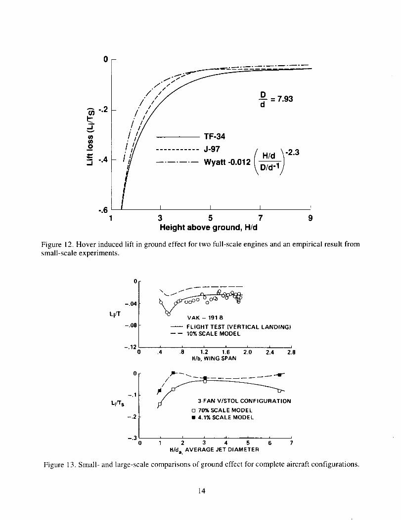
Work at NASA Langley showed importance of exhaust decay
on induced hover lift loss. Small-scale results on figure 12
could not be duplicated which led to study of test facili-
ties. Results are affected by test chamber volume, relative
size and texture of the ground plane, and model exhaust char-
acteristics. At present level of understanding, accurate
ground effect results can only be assured by testing large
scale with realistic power plants, outside where test cham-
ber volume is infinite. Figure 12 shows full-scale engines
had more suckdown than small-scale results. Figure 13 shows
lift increment in ground effect for VAK-191B STOVL and i0 %
scale model. YAK suckdown is twice that of the model. The
above and more lead to these lessons learned:
* Study Reynolds number sensitive devices at large scale
* Propulsion systems must be accurately modeled for
transition aerodynamic studies
* Ground effect studies require (i) well modeled propulsion
systems and (2) an open air test site
* Propulsion modeling must be large scale and the engine
similar to that planned
9

STOVL Components
Emphasis is on inlets and exhaust devices. For STOVL,
inlets range from shallow for fan-in-wing to deep for fan-in-
fuselage. Thus, work on lifting engine inlets is included.
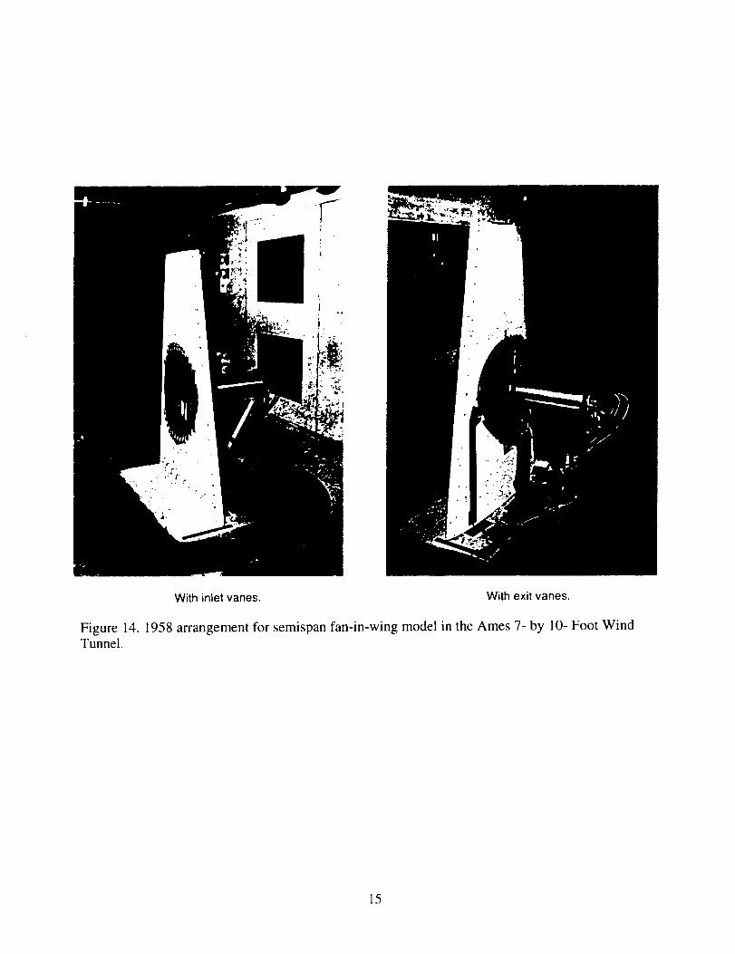
In 1956 NASA (i.e. Hickey) conducted the first wind
tunnel test of a fan-in-wing model. Figure 14 shows the next
effort in 1958 using a fan (i.e. a 20 in dia propeller) in a
wing semispan. Results were used to design the XV-5. Re-
sults show for velocity ratios where fan blades are highly
stressed (below V/Vj=0.3), streamwise and spanwise flow
distortion was small. Thus in 1958 it was already question-
ed whether lift-fan inlets needed flow turning devices.
From early work on thick wing subsonic designs, atten-
tion turned to the thin wing supersonic designs. To provide
a thin fan for thin wing models, the stator was removed from
the X-353 and BLC was used on the outboard part of the
inlet, see figure 15. Except for the unmodified hub, this
first thin fan could fit in a 60 deg swept back triangular
wing 5 % thick. Large-scale aircraft model results using
this thin 5.2 ft dia fan show, compared to the thick fan,
(I) about equal static performance, (2) slightly better for-
ward speed performance, and (3) effectiveness of the BLC - a
jet of magnitude 3 % fan thrust increased fan thrust 30 %.
This and other research lead to questioning whether a thin
fan in a supersonic wing could be shaft driven because of
depth of right angle gear drives, or if it could have
variable pitch because of depth of pitch change mechanisms.
Turning to deep inlets, figure 16 shows lift engines (J-
85s) in a large-scale model. Figure 17 is a comparison of
the deep inlet of figure 16 and others also discussed. One
conclusion is that a small amount of tilt and using the tilt
to increase the upstream inlet radius is a powerful tool to
improve recovery and minimize distortion.
The paper includes a section on exhaust deflectors that
range from cascades of vanes to multi-segmented hoods to
rotating tail pipes.
Lessons learned pertaining to this section on STOVL
component aerodynamic design include the following.
* Lift fans
* Lift-fan inlets don't need flow turning devices
* BLC inlets reduce fan depth and are highly effective
* Small tilt of a thick duct improves fan performance
* Fan should be near top of duct
* Exhaust deflectors
* Cascades can deflect fan flow 60 degrees
* Lift/cruise fan deflectors have a 6 % thrust loss
I0

STOVL Aerodynamics
The section emphasizes ground effects and transition
aerodynamics during the powered-lift flight mode. Ground
effects during hover, because of referenced coverage by
others, is not discussed except for exhaust gas reingestion.
Of potential problems, a catastrophic one is engine stall
from the ingestion of cells of hot air. Such was recognized
early and was the driving reason for the shape and arrange-
ment of the XV-5. The problem could become worse because
new designs will probably have higher temperature engines.
Considerations for solution include configurational layout,
exhaust deflection, and operational procedures.
Ground effects at forward speed can be measured in a
wind tunnel, even in those not equipped to eliminate the
wind tunnel boundary layer. Sometimes investigators
artificially limit testing because of wind tunnel flow
breakdown. Tests should continue to that low speed at which
exhaust flow reflections impinge on the model.
Operation of lift fans in transition can induce majorforces over and above those from direct thrust. A jet-in-
crossflow, figure 18, entrains air from the surrounding
environment and may induce negative lift on surfaces. Most
results and prediction techniques for jet-in-crossflow rely
on experiments with wall jets. The wall acts as a plane of
symmetry and prevents flow across that plane. Few aircraft
are configured in that way so jet trajectories, entrainment,
and induced forces could be different. Such a case that
involved operation of the XV-5 nosefan is discussed.
Transition aerodynamics must be understood, and it is
one of the reasons for wind tunnel investigations of many
aircraft geometries. Figure 19 tabulates major parameters
of 13 large-scale lift-fan powered models that were tested
in the 40-by 80-ft tunnel. Figure 20 shows the variation of
induced lift with airspeed for several of the models. A fan
mounted near the wing trailing edge produces positive in-
duced lift. Some geometries yield no, or even very negative
induced lift. Concern is not just with induced lift itself,
but that induced lift also induces pitching moments. Fig-
ure 21 shows pitching moment variation for several lift-fan
installations. As shown fan-in-wing types can exhibit large
positive changes in pitching moment. The moment variation
from podded configurations is less, and easier to handle.
Lessons learned for this section include:
* Turbulent hot gas cells stall engines. The relngestion is
controlled by configurational layout, by exhaust deflec-
tion, and by operational procedures.
* Lift-fan operation induces a substantial downwash, pro-
vides induced lift, and induces moment.
I]

Prediction Methods
Recognized is the need for sophisticated prediction
techniques using paneling and complex models of the jet in
crossflow. Stressed is the usefulness of simple semiempiri-
cal prediction. The methods presented are compatible with a
personal computer. Addressed are Ground Effects, Jet-in-
Crossflow, Fan-in-Wing, and Tilting Lift/Cruise Fans. To
illustrate this section, the Fan-in-Wing is summarized.
A fan-in-wing can be represented by a mid-chord jet
flap, located anywhere spanwise or chordwise as long as it
is bounded by the wing. As shown in figure 22, a two-dimen-
sional lift coefficient is developed for the wing section
through the fan. Two-dlmensional jet flap theory is used
for lift on the wing section upstream of the fan. Since the
aft section of the fan has separated flow on the under sur-
face, a lift coefficient of -V/Vj to the 3/2 is assigned.
Front and rear lift coefficients are joined to give a com-
plete two-dimensional lift coefficient inside the brackets
(see figure 22 equation). The terms outside the bracketsconvert to three dimensions and from lift coefficient to
lift ratio. Predictions are compared to measurements for
induced lift, lift ratio, moment variation, ram drag, total
horizontal force, and more. Figures 23, 24, and 25 are
included herein to illustrate these comparisons. Agreement
is sufficient for usefulness of these simple methods.
Lessons learned for Prediction Methods include:
* Jet flap and 3-D wing flap theory induced lift predictionmethod
* Momentum methods for thrust/drag
* Momentum/jet flap for lift/cruise
Acoustics
The paper includes a section on acoustics. Lessons
learned and/or findings are:
* A number of ways to minimize lift fan noise will not
compromise performance or volume, and therefore should be
included in any design.
* An increase in fan depth and added treatment can further
reduce noise, but with penalty.
* A thin statorless fan can have noise levels comparable to
the best conventional fan.
* Forward speed increases lift fan noise and jet mixing
noise.
Concluding Remarks
This is a comprehensive paper with 90 figures, most of
which are presentations of technical results.
12

DUCT ANGLE OF ATTACK AT WHICH INNERLIP STALL OCCURS
LEADING-EDGE
IO0 RADIUS. _n /INSIDE SURFACE
12r,. 0eg
50
4 _ x-Z2ASMALL SCALE
L A J
0 ,5 t .0
t/T c
I I I I .
3 5 7
V:V_
DUCT ANGLE OF ATTACK AT WHICH OUTERLIP STALL OCCURS
\\ INSl0[ SU R FAC, I_
X- ZZA
SMALL SCALE
• • , = _ J
0 $ I.O
_/T C
LJ B i3 5 7
VVI
Figure 10. Effect of Reynolds number on duct inlet flow separation.
L/Ts
1.5
1.0 (
.5
Small-scale
© No wall corrections[] With wall corrections
Large-scaleL No wall corrections
With wall corrections
_. ....... -_ .... ;_--..... _z_.... --_ __
L I i J
0 .1 .2 .3 .4 .5
v/vj
Figure 11. Comparison of small- and large-scale model lift variation with forward speed.
13
/ ,/11/ /'"J D
/ /,'/ _ =_.93
-.2r ! ,'/"- / /,7| /,,_/ _ TF-34
'1o |Iil ........... (H/d\ -2.3
..6 | I I I I t1 3 5 7 9
Height above ground, H/d
Figure 12. Hover induced lift in ground effect for two full-scale engines and an empirical result from
small-scale experiments.
Li/T
-.04
-.08
VAK - 191 B
FLIGHT TEST (VERTICAL LANDING)---- 10% SCALE MODEL
-.12 , = , _ I I I0 .4 .8 1.2 1.6 2.0 2.4 2.8
H/b, WING SPAN
Lt/T s
0
-.1
[] 70% SCALE MODEL
-.2 • 4.1% SCALE MODEL
-.3 l l l I I
0 1 2 3 4 5
H/da,_ AVERAGE JET DIAMETER
'__ON
I I
6 7
Figure 13. Small- and large-scale comparisons of ground effect for complete aircraft configurations.
14
I
Figure 14.Tunnel.
With inlet vanes. With exit vanes.
1958 arrangement for semispan fan-in-wing model in the Ames 7- by 10- Foot Wind
15

Fan front frameand bellmouth
Conventionol fan
(GE X 353 Fan)
Circularinlet
guide vane
_t i itoUrb i ne
"_'Fa n stator
Outboard + Inboard
U ppe_
_rface
Reduced lhickness fan
Figure 15. Cross sections of the conventional and modified statorless fan.
_ ?i_ _!....._ _----__
Variable louvers" Diverter valve
Figure 16. Large-scale lift/lift-cruise model
16

.,,_, r-_10
-_ .08 ..... -.... 1"_ _._e_,g,
¢Z._/ "" "_1 / Tip turbine/ J_--_" "_ _ _0 ..__L_. Rotor _
0 .4 .8 1.2 1.B •
Figure 17. Comparison of performance of three left engine inlets.
:rIBBON OF HORSESHOE
VORTICES ALONG
EMPIRICAL JET TRAJECTORY
LOCAL VORTEX
STRENGTH
DETERMINED BY
BALANCING
CENTRIFUGAL FORCE
DUE TO TURNING JET
MOMENTU_
\
\
\
Figure 18. Typical model of a jet-in-crossflow.
17

MODEL TYPE
1 Fan-in-fuselage F
2 Fan-In-wing k
3 Fan4n-wlng ii k
Fan4n-wlng, 6 fans AFT4 Fan-in-wing, 4 fans AFT
Fan4n-wing, 2 fans AFT imFan-in-wing, 6 fans forward
5 Fan4n-wing k
Tandem IIit fan br
6 Fsn4n-wlng, 2 fans AFT •Fan-in-wing, 2 fans forward p_-
Folding lift fan k7 Rotating cruise fan
Tandem podded lift fan L8 2 fans forward P2 fans AFT
Lift-cruise fan9 2 fans forward (podded)2 cruise fans AFTLow wing tandem lift fan L
10 2 fans forward (podded) p.Fan4n-vdng, 2 fans AFTLow wing, 2 lift
11 Fans forward2 lift/cruise fans AFT
1 fan forward k12 2 liflJcruise/'D' deflector
13 2 tilting lift fansF
WING SWEEP OFASPECT QUARTER
RATIO CHORD LINE
5 0°
3.5 16 °
3.11 18°/25 .
3.43 20 °
2.2 52.4 °
5.8 (basic) 35 °3.44 (gross)
5.8 35 °
5.8 (basic)4.04 (gross) 350
5.e (basic)4.4 (gross) 35°
s.6 (basic) 35 °3.7 (gross)
8.14 23.5 °
4.5 25 °
7.6 0/10
Af D D XTAPER REFERENCEi
S C b C
.5 .084 .552 .147 .25 3
.5 .099 .428 .269 .392 14
.32 .147 .U .349 .43 9
.115 .292 .505 .42.47 .076 .268 .336 .43 NASA
.038 .245 .156 .44 TN D-4233
.115 !.292 .505 .322
0 .12 .335 .363 .63 16
.073 .796 .164 .286.3 .036 .398 .164 1.24 29
.036 .398 .164 -.657
.3 .123 29
.086 .946 .164 NASA.3 .043 .473 .164 -.80
.043 .473 .164 1.16 TN D-6234
.094 _ .164 NASA.3 .047 .473 .164 -.80
TM X-62151.007 -- .164 m.080 -- .165 --
.3 .040 .473 .165 -.80 NASA.040 .370 .165 1.19 TM X-62102
.115 -- .134 NASA.23 .057 .48 .134 -2.56.057 .48 .134 2.61 TM X-62231
.3 .101 NASACR-152181
.47 .12 -- .101 -- 20
Figure 19. Geometry of large-scale lift-fan-powered models tested in the 40- by 80- Foot WindTunnel.
18

1.6 Model
6b
1.2
4a.8
Li / Ts
.4 2
0
6c
-o4
• °
v/v II I I t I 1 I
0 40 80 120 160 200 240
V, knots
Figure 20. Induced lift variation with airspeed for several fan-in-wing configurations.
.6
j_
/j/
/,/
/J
-/_
_ MODEL.4
o
_5
> .2
uJ(p
-,4 1 r
0 .2 3 .4 .5 6
FLIGHT VELOCITY RATIO, V/V i
0 25 50 ,'5 m/secI_ -- 11 11 £1
0 50 I00 150 knoIs
VELOCITY
Figure 21. Pitching moment variation with airspeed for several fan installations.
19

SCHEMATIC FOR INDUCEDLIFT CALCULATION
THE V2 CL_I r s,FLOW FIELD L i _ C_. _jWITH FAN T S V .2 47rA /S LOPERATING I s f Szd
8j =90-,8
s3 S2=A,IAREAS FOR INDUCEDLIFT CALCULATION
Figure 22. Schematic for induced lift calculation.
1.4
:1_"8÷
"-I"" .6
.4
.2
_ef
0
....... 35.5
-- ref. 10
..... calculated
I I I I I I
0 .1 .2 .3 .4 .5 .6
v/vj
Figure 23. Calculated and measured variation with airspeed for three exit louver angles.
2O

.5
.4
D .3Ts
.2
.1
°f .°"°_ i II
/_)// O _ Ref. 10
- //./ T V
" T s Vj
/ I J t I I I J
0 .1 .2 .3 .4 .5 .6 .7
V
vj
Figure 24. Calculated and measured variation of drag with airspeed.
.6
.$
.4
.3
2
Fx-- O!Ts
-.1
-.2
+.3
-4
-.5
I r I I
-- v"v'L'_lc_" .... "('-U
0 0 1t=21
I L L
.1 .2 .3 .4
V Vl
]6
Figure 25. Calculated and measured horizontal forced with a lift fan operating with three exit louver
angles.
21


Summary of the Technical Paper by Cook, Reference 3
Doak VZ-4 Ducted Fan Wind Tunnel Tests
Figure 26 is a ducted fan on semispan in Ames 40 x 80.
The fan had inlet guide vanes, fixed pitch blades (variably
tested by manual set), and exit vane with flap. Figure of
merit was 78%, decreasing as blade angle increased. Thrust
for blade pitch was 80 ib/deg; for inlet guide vanes used on
the VZ-4, 12 ib/deg. These inlet vanes were 15% as effective
as blade pitch for lateral and height control near hover.
The exit vane overcame high pitch-up moments caused by
the tilted duct at forward speed. Figure 27 shows the set-
ting of vane 10/flap 20 deg reduced maximum out of trim mo-
ment by 50%. Exit vanes reduce duct tilt in transition
which helps control duct lip stall. Exit cascades, figure 28,
were evaluated. Figure 29 shows, compared to vanes off for
the original Doak duct, one cascade tested increased descent
rate by a factor of 2.5. One lesson from this 1960s workwas that exit vanes are effective for alleviating the common
V/STOL problems of descent rate capability, deceleration in
steep approach, and air braking needed to approach hover.
Wind Tunnel Tests of X-22 Lift/Cruise Fan Aircraft Model
Section includes 0.57 scale aircraft model, and an iso-
lated full-scale X-22 fan. Emphasized is the lesson that
adequate margins must exist during descents; deceleration
margin of -0.05 to-O.lOg, plus 2 to 3 deg descent angle
margin for maneuver. For the basic configuration, maximum
descent angle was -6 to -i0 deg. With margins of -.05g and
-3 deg, descent was reduced to 0 to -2 deg, which would be
of little practical use for terminal area operations. Other
findings were reasonable ground effects, need for a good
wing for L/D, higher pressure ratio fans to reduce cruise
fuel consumption, and benefits from variable blade pitch.
Avrocar
These wind tunnel tests, figure 30, complement flight
section in Reference i. Figure 31 shows the effect of ground
height on lift, which increased 250% as height decreased
from h/D values of 1.0 to 0.15. Since these tests, this
ground effect phenomena has been utilized by air cushion
machines. Other findings or lessons were (I) lower power
required at forward speed in ground effect compared to out
of ground effect, hence the resulting low speed of the Avro
car, (2) large inlet momentum drag and high duct loss were
two reasons why out of ground effect forward speed wouldhave been limited to 59 knots at 4500 pounds, (3) Avrocar
had neither forward thrust, nor pitch control, nor lift to
fly above 70 knots out of ground effect at design weight.
PRECEDING PAGE BLANK NOT FILMED
23

General Electric Lift/Cruise Fan - Wind Tunnel Tests
Tests were conducted of a I.I pressure ratio ducted
lift/cruise fan, 62.5 in dia, driven by exhaust of a J-85.
Exit area was varied for effects on static and forward speed
performance. Results show the need for a variable area exitnozzle for a fan with fixed blade angle instead of variable
blade angles. Presented are the effect of duct external
drag and duct stall. With margins, descent performance was
less than -i0 deg for all speed conditions and duct angles
of 50 deg or more. Once duct lip stall occurred, large
increases in rpm were necessary to unstall the lip.
Reingestion of V/STOL Lift-Engine Fighter Models
Models were powered by J-85s, with internally fixed
lift engines, figure 32, (see complementary results in Refer-
ence 2), or with retractable engines. All exhibited exces-
sive thrust loss and compressor stall with thrust vectored
90 deg, i.e. vertically. Of three exhaust nozzles tested
with the fixed engine, figure 33, the slotted nozzles pro-
duced less gradient and average inlet temperature, thus less
lift loss than the conical or bifurcated nozzles. It was
demonstrated on the retractable engine model, and believed
true on the other model, that vectoring lift engines to a
small forward angle and lift/cruise engines aft to balance
the aircraft alleviated exhaust gas ingestion and thrust los-
ses. The aircraft could takeoff and land with decelerating
approaches while surrounded by exhaust but relatively free
of ingestion effects and losses. In addition to that lesson
learned, pointed out is that results may be applicable to
aircraft with the higher pressure ratio lift fans, and that
the technique might also be used to alleviate suck down.
Grumman-698-111 Tilt Nacelle V/STOL Model
Figure 34 is the powered model in the 40 x 80. Nacelles
with lift/cruise fan engines tilt forward of the wing. The
tilting nacelles during transition change center-of-gravity
alot (about 9 in at landing weight). This affects control
power available after trimmimg moments due to c.g. shift.
The magnitude of c.g. shift is very unusual for a V/STOL air-
craft. Figure 35, descent performance and inlet fan stall,
indicates trimmability over a wide range of nacelle deflec-
tion, angle of attack, velocity, and flight path angle. How-
ever, large nose up pitching moments reduce control avail-able for maneuver to 50% of acceptability, figure 36. The
large pitch up is mostly due to the long inlet and its
height above the c.g., and to the large area of unprotected
wing center section over the fuselage. One proposal was to
reduce inlet length by I ft to achieve sufficient reduction
of pitch up moment. However, during ground effect static
tests, lack of ingestion and thrust losses was attributed to
some degree to the high location of the inlet.
24

Fan-in-Wing Stall Boundaries
The fan-in-wing as in the XV-5 was subject to fan stall
as well as wing stall that affected fan stall and vice ver-
sa. Such effects were examined in the wind tunnel usinq the
5.2 ft dia fan in different wings. Figure 37 shows the vari-
ation of tip speed ratio for stall with angle of attack.
Shown is the aircraft flown level at a -I0 deg descent angle
at 70 knots, and flown parallel to the -i0 deg descent path.
At I0 deg wing angle of attack, for the deck level approach
the margin to stall is small--2 to 3 deg angle of attack and
I0 knots speed --which would be critical to gust or maneuver
requirements. With deck parallel, 12 deg angle-of-attack
margin exists and a factor of two up to 150 knots could be
flown before reaching the stall boundary at an angle of
attack near 0 deg. Lesson learned: the technique used for
approach has much to do with fan-in-wing stall margins.
Conceptual Design Considerations
One design study discussed is on the Lift Fan Research
and Technology Aircraft (LFRTA). Figure 38 shows modified T-
39s, a McDonnell gas-coupled and a Boeing shaft-driven de-
sign. Figure 39 shows two types of shaft-driven systems.
Findings or lessons from the LFRTA include the following.
* Need for design guidelines specifically for technology
demonstrator aircraft. The paper presents one such publica-
tion. Each of the many subjects in it is a lesson learned.
* Shaft-driven was 7% more efficient than gas-coupled, but
its higher weight offset some of the difference.
* Gas-coupled had fixed blade pitch whereas shaft-driven
had variable which offered advantages discussed later.
* Problem for shaft-driven 1975 LFRTA was fatigue life and
qualification of gears. Figure 40 shows gear tooth bending
stress versus pitch line velocity. Pitch line velocities
are high compared to most gears for helicopters of that era.
* Gas-coupled needed development of large ducts and high
temperature valves. For small aircraft volume available for
ducts is not sufficient.
Points made for the LFRTA or other designs include:
* Compared to fixed fan blade pitch, variable pitch offers
(i) faster response, (2) less fan thrust loss for large
control inputs, (3) much better cruise performance, and (4)
potential for reverse thrust at low speed of one fan tobalance multifan aircraft for one fan out safe flight.
* Horizontally mounted lift fans with exit louvers at -30
deg produce deceleration forces that are much greater and
more effective than those from simply deflecting or tilting
the cruise fan or engine thrust.
* Fans in fan-in-wing cause penalties in wing weight, thick-
ness, and volume for fuel; but horizontal lift fans have
merits as stated above, and statorless fans can alleviate
thickness problem.
25

Technology Utilization for Conceptual Design Studies
In his introductory remarks, Mr. Cook says his paper
includes "design integration problems - - including lessons
learned during more recent conceptual design studies related
to a small executive V/STOL transport aircraft". Mr. Cook
has devoted a portion of I0+ retirement years to conceptual
design of lift-fan V/STOL aircraft. For creditable design,
one must understand the lift-fan technology that has been
developed over the past 35+ years, where to find it, and how
to use it. This Technology Utilization section is a 4-page
outline covering subjects that must be addressed. The en-
tire outline could also be called "Lessons Learned".
The outline is organized into Ii topics: horizontally
mounted lift fans, lift/cruise fans, control systems and
simulation, flight tests, structural weight and materials,
lift plus lift/cruise fan model wind tunnel tests, conver-
sion, control and stabilization systems, technology demon-
strator aircraft, conceptual design tradeoffs, and potential
military use. Subsection I follows:
I. Horizontally mounted lift fans (Hickey & Kirk)
A. Data from static and wind tunnel tests for following:
I. Fan sizing and thickness
2. Wing sizing function of fan size
3. Hybrid configuration-effect of fan downwash on aft wing
4. Fan induced lift, drag, and pitching moments
5. Determination of lift fan stall boundaries with cross
flow and angle of attack
6. Inlet requirements for vane, and closure door or vanes
B. Geometric characteristics of lift fans dependent on num-
ber of fan blades and blade area
Lift-fan technology is such that technology demonstrator
aircraft will precede production aircraft. Thus one subject
of interest is subsection IX (paraphrased herein).
IX. Technology demonstrator aircraft (TDA)
A. Geometric size, aerodynamic shape and details, would be
same or close as possible to prototype
B. Structural strength of aircraft and components would be
designed for 235 rather than 350 knots, corresponding to
dynamic pressures of 182 rather than 405 Ib/sq ft
C. Design for 2-place with instrument package for flight
to prove technically, then demonstration flying, then
as 3-place with ½ fuel load of production aircraft
D. Simplifications that are weight and cost effective, re-
sulting in TDA weight 22 to 25% less than production
i. Lift and lift/cruise fans designed for final thrust,
but flown on TDA initially at 75%, thus requiring low-
er initial power requirements as well
2. As development testing of fans was completed to design,
gradually increase gross weight to production value.
26

VANE CHORD
-%.
Figure 26. Model with duct exit vane.
2800
(I3
2400
l--b[..
2000W
0
:E 1600
Z
"r"
2ooI:L
EXIT VANE ANGLE/FLAP ANGLE
800 i I0 I0 70
/_OFF
! I I I
2O 3O 40 50 60AIRSPEED, KNOTS
Figure 27. Reduction in pitching moment due to duct exit vane deflection.
27

Original duct
exit --_.
J
Vone hinge points "-J
45"
-- ix t/8_ 16 l/4- 16,_.
8racinq "_ , 14- ------I
- ".,..Lm"-" //'--i i i -
6 1/2--'_ ,
Ixl/8 Support strop 12-
15 1/2-17 1/2-
45 ° Coscode 18 l/2- _ ,
I/2_
-- _ 2_3
m
(Air dimensions tn inches}
16 1/4 =
16-_
II _ ...__1
ixi/8 Support strop _/ 6 I/2---
14 l/2-_
0 ° Coscode t 7 I/2-
{a) Vane mounting detail
Figure 28. Exit vane dimensions and arrangement.
10 t/4
28

3,000
E...._2,000
0
0>
C
u 1,000
0
8n/_c/Sv, degrees _0
1 /0/10
1 I L I
20 40 60 80Horizontal velocity (knots)
Figure 29. Descent velocity boundary due to stall of the upstream duct lip for the vehicle at 0 degwing angle of attack using the 0 deg cascade with a vane chord-to-gap ratio of 0.83.
29

Figure 30. Rear view at minimum test height.
30

3.0--
2.2
"_1.8
ozl.4
t
1.0 I I0 .2 .4 .6 .8 1.0 1.2
h/D
Figure 31. Variation of ground effect with height to diameter ratio.
Figure 32. Lift engine model mounted in wind tunnel.
31

I00
AT, "F
5O
.3
.2
TtWUSt loss
Tlw_t,%T,OO
.I
0
0
0 Storied
(
k
C_col "_ _k
_q .... "9--. x,
Lift
Thrust,_,T.OO
1.0
lf
ib
.... No doors
With 0oocs on
tocwordt usr,etoge
80 70
Thrust or_le from tmrizo_foI, deg
Figure 33. The effect of exhaust vectoring on temperature rise and thrust loss; internally fixedconfiguration, H/D = 5.0.
32

Figure 34. V/STOL model in 40- by 80- Foot Wind Tunnel.
30
25
20
15
10
¥, (deg) 5
0
-5
-10
-15
-20
-25
Landing wt = 13,654 Ib
Do
C 0D•
O •
D .
[312
0 20 40
(_NAC = 5
62% max power
_NAC (deg)
× 20' v 30
• ' o 50o 40"" 60
o' ,_, 68• • Solid = inlet limited
4• 40 _¢' •
a j• • ,q _ i ¢
, • • e • III
• ,re % •
@ " ,,o , ,-,'_ "_vNAC = 5
_m. idle power"o" °A•
# ,
L i p
60 80 100 120 140 160
V (knot)
Figure 35. Trimmed performance.
33

DO
e
rad/sec 2
<> 6NA c,' 68DEG
O 60 DEG
_] 50 DEG
1.8
1.6
00
1.4
1.2
1.0
tO
m
o.e=L
0.6 _.ur)
n
p.
04
ii
0.2
ii
0 • 1
-o.2 0
0-0.4
-0.6
60
0
I
LIrp sym - I¢_ c9 (GW " 13654 Ib)
Stool1 sym - 11o.cg (GW - 16768 Ibi
i i I
70 80 90
V (KTI
1921-311(T)
R$1.050|-]I l AS
Figure 36. Longitudinal maneuvering capability.
34

16- 0 O0 •
14- OO_. •
12 0 •
10 ×>0
8 0
; 6 o
0 .2 .4U-- - Tip speed ratioVt
• Stallllcl
0 Open mymbo_l-
unmlllled
X X Decklevel
lOdescenl
Deck parollel
10 descent
i I.6
Figure 37. Effect of angle-of-attack on tip sped ratio stall boundaries.
• TttREE FANS
• 110,000 TO 130,000 N 125,000 TO 29,000 lb.) VTOL GROSS WEIGHT
• 42,0(]0 N (9,500 Ib.JUSEFUL LOAD
Figure 38. T-39 modification.
35

THRUST VECTORING NOZZLE TILT NACELLE
LIFT/CRUISE FANS\
f_ COMIINER'_:Y(_ _'" GEARBOX
LtFT FAN
DDA XTTOt ENGINES (31
LIFT/CRUISE _ _FANS (2) /
DDA XT 701 (31
ENGINES \_ _)_LV COMBINER
LIFI FAN CLUTCH __ /_"_j
_ DRiPBO X
LIFT FAN
Figure 39. Shaft drive systems.
180
170
%Z
"_. 150
ud 140
I-.130
<[ 120t.-
(_ 110(.3
100
300 -
190
i
t4J
200_ p-
U<
-8150
720 z -
10 --
0 -
250
Ii
0
HIGH POWER
HELICOPTER
Q SPIRAL BEVEL
CH47C CH53 "_- "_
II_ Z_RTA MAX. \. CH47C
1 I
CONTROL \'\ MCAIR (Ref. II
_ SPIRAL BEVEL
//
RTA E)_---_--- _OEuI:_{HR;I LlgdAL
NORMAL T,O, _
1 I I I
5 10 15 20 25 30
PITCH LINE VELOCITY, fpm X 10 -:3
1 1 L I 1 I [ I I 1 I0 1 2 3 4 5 6 7 8 9 10
PITC}! LINE VELOCITY. mpmX 10 -3
Figure 40. Effective pitch line velocity on stress levels.., contact.
36

Summary of the Technical Paper by Franklin, Reference 4
Initial sections concern V/STOL lift fan research tran-
sport designs of the 1970s. Presented for four contractual
designs are aircraft description, control effecter concepts,
flight control modes, control power, dynamic response of fan
thrust and more. From moving-base simulations, presented
are pilot evaluations of flying qualities and control char-
acteristics, showing a preponderance of "Satisfactory" rat-
ings when appropriate control modes were chosen. Some spe-
cific comments worth noting were (I) a preference for thrust
deflection to control longitudinal translation in hover at
constant pitch attitude, as opposed to modulating attitude,
(2) preference for thrust deflection rates of 20 to 25
deg/sec for transition (5 deg/sec was inadequate), and (3) a
difficulty in maintaining control during low power descent
due to loss of control authority.
Mixed-Flow Remote-Lift Aircraft Design
Figure 41 shows the mixed-flow remote-lift STOVL fighter
aircraft concept, used for following simulation program. The
aircraft's size is comparable to that anticipated for a
STOVL Strike Fighter (SSF), and use of propulsive and aerody-
namic controls is similar. Generalized NASA results may be
applicable to future SSF designs. Propulsion features in-
clude mixed fan and core streams ducted to lift nozzles or
to thrust deflecting cruise nozzle, ventral nozzle diverts
some mixed flow for pitching moment to counter that of lift
nozzles, deflected lift nozzle thrust for longitudinal
force, deflected cruise nozzle for pitch and yaw, and for
transition the flow is smoothly transferred between nozzles.
Pitch--symmetric empennage deflection, reaction con-
trol, thrust transfer between lift and ventral nozzles, ver-
tical deflection of cruise nozzle. Roll--ailerons, lateral
thrust transfer for differential lift nozzle thrust. Yaw--
differential empennage, reaction control, lateral cruise
nozzle deflection. Longitudinal force--thrust transfer be-
tween lift and cruise nozzles, deflection of lift nozzle
thrust. Height control--thrust. For transition either at-
titude or flightpath stabilization and command augmentation
system (SCAS) was available, and a heads-up display (HUD).
Control Mode Evaluations
Figure 42a shows pilot assessment for decelerating tran-
sition under instument conditions to a breakout at I00 ft.
Unlike for attitude SCAS alone, with attitude-plus-flight-
path SCAS the pilots managed the entire transition with min-
imal effort. Figure 42b is for vertical landings on an air-
field, ceiling I00 ft, visual range 1200 ft, visual condi-
37
tions for landing. Unlike for attitude SCAS, for attitude-
plus-velocity SCAS, control of vertical axis and of trans-
lational horizontal velocities was easy. Figure 42c is for
recovery aboard ship. Assessments for attitude SCAS were
poor. For attitude-plus-velocity SCAS, satisfactory ratings
were obtained up to those high wind over deck (WOD) and sea
state conditions that would limit air operations aboard ship
for concerns other than aircraft flying qualities.
Control Usage
Presented are required pitch, roll, and yaw authorities
from simulation of the STOVL design, including rationale.
Pitch control, figure 43: In transition, for maneuvering and
effects of turbulence, control power of 0.20 to 0.25 rad/sec
squared would provide for most demands. 0.14 to 0.27 would
accommodate most demands for attitude SCAS for airfield vert-
ical landings; with velocity command, vertical landing can
require 0.17, independent of winds and turbulence. For ship-
board landing, with attitude command alone, peak control
usage is 0.38 rad/sec squared or less; with attitude-plus-
velocity command SCAS, a requirement of 0.2 should suffice.
Total available for conceptual STOVL was 0.42, with 0.08 to
trim 34 kt wind, so pitch control was more than adequate.
Roll control, figure 44: Note that for this STOVL configura-
tion in turbulence during transition, current criteria (Ref-
erences in figure 44) call for insufficient control. Based
on this simulation, a roll control authority of 0.9 to 1.2
rad/sec squared would be necessary to satisfy demands for
maneuvering and control in turbulence. Control use for air-
field vertical landing is within referenced criteria, rang-
ing from 0.2 to 0.4 in heavy turbulence for both attitude
and attitude-plus-velocity SCAS. For shipboard landing, re-
sults agree with criteria for light winds, but not for high
wind over deck conditions. Operation aboard ship with high
W0D is limited by capability to recover to the deck rather
than by aircraft controllability. And here is a case where
attitude-plus-velocity SCAS required more control authoritythan attitude SCAS alone. Total roll control available for
the STOVL in basic configuration was I.i rad/sec squared, so
it was necessary to augment the baseline with reaction con-
trol to handle high WOD for recovery to the ship.
Yaw control, figure 45: For transition and for airfield
vertical landing, criteria all exceed these results by a
significant degree. The disparity is likely attributable to
good yaw stability augmentation and lower sensitivity to
disturbances for recent ST0VL fighter concepts compared to
the collection of aircraft on which the earlier criteria
were based. Total yaw control authority for this STOVL
design was 0.28 rad/sec squared.
38

Thrust Transfer Rates
Ability to achieve adequate rates of thrust transfer
between propulsion components for pitch and roll control is
an important aspect of control system dynamic response.
Pitch control, figure 46: Most significant control rates are
for shipboard landing. Maximum rates of 3 to 6 klb/sec with
longitudinal velocity command SCAS occur at highest WOD.
Thrust transfer rates are also expressed in time rate of
change of control power for this aircraft, which can be used
to define the relationship between peak control usage and
the effective bandwidth of control that can be achieved
without encountering the control rate limit. For example, a
maximum thrust transfer rate of 2 klb/sec, which corresponds
to a rate of change of angular acceleration of 0.5 rad/sec
cubed, and a peak control usage of 0.05 rad/sec squared
would imply a rate free control bandwidth of I0 rad/sec. For
pitch (and roll) control system designs, variations in band-
width within a range that provided satisfactory flying qual-
ities for the low speed flight tasks did not have a signifi-
cant influence on peak control rates or usage. Designers
have considerable latitude in choice of control bandwidth
while avoiding excessive control use or actuation rates.
(Paper also covers thrust transfer rates for roll control.)
Thrust Control
One section is on influence of ground effect and hot
gas ingestion, figure 47. Experiments were conducted on the
vertical motion simulator (VMS) to evaluate in general these
effects on thrust margin necessary to control height and
sink rate during airfield vertical landings. The results
were validated with specific simulation assessments with the
YAV-8B. Boundaries are presented that define acceptable and
unacceptable regions for combinations of mean ground effect
and ingestion and thrust/weight ratio. The shape of the
boundaries is established by height control out of ground
effect for positive ground effect, on abort capability at
decision height for neutral to moderately negative ground
effect and ingestion, and on control of sink rate and hover
position to touchdown for larger negative ground effect.
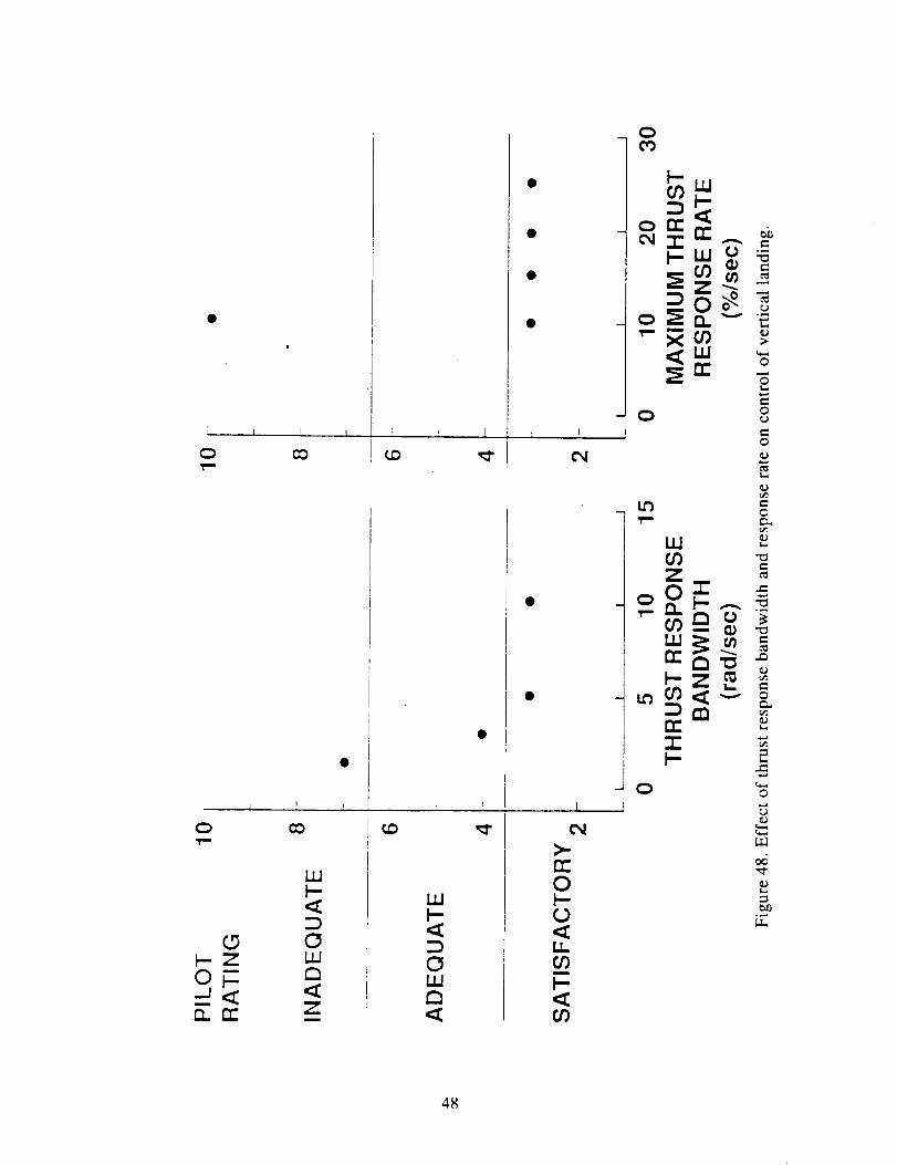
Another section is the influence of engine dynamics,
figure 48. These data apply to manual control of thrust for
vertical landing with attitude SCAS only. Shown is that a
bandwidth of thrust response of the engine core of 4 to 5
rad/sec is sufficient to achieve satisfactory ratings for
height and sink rate control. To a point, vertical landing
is insensitive to maximum rate of change of core thrust,
which is associated with engine acceleration limits imposed
by maximum allowable temperatures in the core. Maximum
thrust response rates from 25 to nearly I0 %/sec were toler-
able for height control. At about i0 %/sec, thrust rate
39

limiting and loss of control were encountered on occasion
for such slow acceleration. Deceleration rate limits are
important to the ability to rapidly reduce thrust at touch-
down, as well as to control vertical velocity in hover.
Accelerating Transition
Pilots' assessments for accelerating from hover to for-
ward flight indicate that flightpath acceleration in excess
of 0.13g is desired for fully acceptable capability. For
0.08g or less the aircraft is intolerant of abuse of control
technique and forces the pilot to devote attention to coordi-
nation of attitude and thrust deflection control. Inter-
pretation of minimum usable transition flight envelope can
be obtained from figure 49. The constriction in the flight
envelope with thrust deflection from 40 to 60 knots, repre-
sented by minimum longitudinal acceleration in level flight,
or equivalently, minimum climb angle, is apparent.
Concluding Remarks
Each result from the research presented could be called
a "lesson learned". The lesson from the sum of all results
reviewed is that they provide the basis for a reassessment
of existing flying qualities design criteria for this class
of STOVL aircraft.
4O

e_
°_
.1>©F-,
.,,._
0E
0
°_
;.q
0 ,,,,,q
41
ORIGINAL PAGE IS
OF POOR QUN,J'I'V

ON
>,(,'1
c_ 22
[_m
[ L !o _ o0
_OEm ea
cr o -"
¢.) _-
,'T <m
om
<_--
-_ (n ÷
o22
c_ =___.< ,<
[_al
L 1 l
c
mm.,_-_
i Q "_ om._ l
r
, oo r12.--'o
: o mcr 3. -" "__a m
• _,_ -_
o
0
E o
= <
.d
--; [_
o
e,, _
o
I r I I
o =
<_ • • •
[] _m._ ad
_o
• I I I [ I )
)
m"_ _ _
_ 2
6
@
e-
o
o
.<
o
_J
°_
42

c_
0fJ)
11 II
"_ N ._c
o •[7 •
Cf)
0CO
__.o
+
..-,
0 []
I
0
\
\
• m
Q Q
[]
• INN • •
Ic_ c_
LO
u
amm
"I"..ior)
Z0F-
Z
F-
0
©
e-
t--
e-
e-
©
.--
e-,o
.<
©
r-
43

II IE
<_o
"_ _ .=orr_© •[] •
u?
0co
>,
coo
o>co +CD I_
•_.. -_,
o D
I I • • • |
QO_
rr\
• IIII
II
cocr_
\.\
_--\
c,i
I
og
i 6be_
I DEx f
O
r_
_zl
r_
,_-il
Z IO Im
B
Z l,_ Ir_ I!-- I
m_O
O
O
O
"a
O
O
.,<
c_
O
=1
44

0 --,0
_._ .r-_..._
me.DO
_- II 11._
.__-_ _
._-" _
-_ :_ .__
0 •
CO
0O9
.n
0
_k
O.
PT
U3•,-- -,_
_Xor" -"
l
• \
! Or',, 1 I
n'C__Z
mC_
Z0m
m
o_Z
n-h-
0
0
©
0
0
e-,
o_
45

Tk=*
0
q) ©
._ II II
E oO 'a
orr_© •[] •
co
Oco
O>0o +
o []
$oeslPeJ
I I I
I
cO
m EEE_E_
eml
• m
.D
t I I
-J WOl-u.
O
O
0n*C_
q
_0
O0
Ng..--a
ZOI--
if)Z
i-.
Ot_
O
C_
O
O
.,.=1
O°_
c-o
r_
o
46

0.025
MEAN
GROUND
EFFECT
AND
INGESTION
(g's)
0
43
430
-0.025
\
//.
,'//
//
-0.05 l
1.0 1.025
Ref. 11 OGE
YAV-8B
LIDS
• ON
• OFF
• ON
• OFF
HGi
NOMINAL
NOMINAL
INCREASED
INCREASED
Ref. 11 IGE
•/// ,
h i = 21 ft
ho=O
I I J I
1.05 1.075 1.10 1.125
Thrust/weight (OGE)
Figure 47. Influence of ground effect and hot gas ingestion on thrust margin for vertical landing.
47
!
Q
0ym
0_-ZOF-
Q.. rt"
L I ! b I
co
1 P I
0
z
F-
0
t_
r
t_
>-rr"0
0
l.l_cO
t_
_ 0
o_uJ
orr_
48

.8
.6
O"-- .4
u .2c=
c-
El.w= 0.mm
LL
--.2
-.4
75
5O
C3
_Jn
t-
en
_. 25
C.
r"
C3
U-
-250
- Sea level
Standard day
Thrust deflection
Thrust
= 25 °
Idle
I J I I50 100 150 200
Airspeed (knots)
Figure 49. Transition flight envelope.
49


Summary of the Technical Paper by Gerdes, Reference 5
XV-5A Flight Tests
Figure 50 is a photo of the XV-5B, a slightly modified
XV-5A. Figures 51 and 52 are drawings of US Army/GE/Ryan XV-
5A. Features are 2 J85s, 2 62.5 in dia lift fans, 1 36 in
dia pitch fan, 12500 ib max gross weight, first flight 1964.
Conventional helicopter controls: collective stick for
height by wing fan exit louvers that spoiled or unspoiled
fan thrust, longitudinal stick for pitch by pitch fan thrust
reverser doors, lateral stick for roll by-exit louvers for
differential fan thrust, pedals for yaw by exit louvers to
differentially vector fan thrust fore and aft. A throttle-
mounted beeper controlled airspeed in fan-mode by collec-
tively deflecting fan exit louvers.
Lessons learned from flight tests of the XV-5A:
* Overall the aircraft performed well, and met the goal of
validating the gas-driven fan-in-wing V/STOL concept.
* Conversion mixer box had 70 relays that required "confi-
dence check" during pilot's pre-flight--too complicated.
* Lacked integrated powered-lift flight controls, hence too
many controls, high workload, impossible for IMC.
* Lateral and directional control decreased as collective
increased. Less control just when needed for VTO and climb-
ing through ground effect disturbances.
* Landing-gear geometry required aircraft to be raised to
level attitude for VTO--prohibited smooth VTOs.
* Momentum drag of pitch fan caused weather-cock and direc-
tional instabilities during very low speed flight. Using a
pitch fan in the fuselage nose was "far from optimal".
* Conversion was "bang bang" type; "most exacting and potent-
ially hazardous operational aspect of the XV-5A". Unaccept-
able--need gradual and reversible type conversion system.
* Figure 53 shows the conversion airspeed corridor was nar-
row. Severely restricted operational flexibility and placed
an unreasonable demand on pilot's adherence to procedures.
* Conversion was accompanied by an abrupt pitch change of i0
to 15 deg. Required excessive coordination--unsafe for IMC.
* J-85 diverter valve gas seal leaked, causing the covered
lift-fan cavities to heat up. Fan cavity temperature indi-
cators had to be monitored by the pilot.
* Gas ducts to the pitch fan were routed under the cockpitfloor. Conversion to fan-mode turned on the "heater".
Cockpit temperatures could get uncomfortably high.
* Outstanding was robustness of the gas-driven lift fans.
Absence of drive shafts, shaft bearings, gear boxes, and
pressure lube systems resulted in low maintenance and high
confidence. Only indicators associated with the three fans
were rpm and fan cavity temperature!
PRECEDING PAGE BLANK NOT FILMED
51

XV-5B Flight Tests
XV-5B was XV-5A modified with mechanical tie between
stabilizer and diverter valve actuators, wider landing gear
tread, improved fuel management system, and improved cockpit
arrangement. First flight was 1968. Investigated steep
terminal area approaches and aircraft noise footprints.
Lessons learned from flight tests of NASA Ames XV-5B:
* Figure 54 shows "deck parallel" descent envelope. Typical
approaches were i0 deg flight path, 70 knots, 20 deg of
thrust vectoring (point B, fig 5). Major source of handling
problems was management of powered-lift. Needed was inte-
grated system that would schedule engine power and fan lift
controls in response to a single powered-lift controller.
* Two glide slope tracking procedures were used. Preferred
was collective for direct-lift-control tracking. When eng-
ing power was used, lags in J-85 and lift fans caused the
pilot to chase glide slope with throttle movements.
* Changing thrust vector angle was effective for controlling
velocity during decelerating approaches. It did induce
flight path disturbances, but the pilot could cope with them
if vector changes were beeped in i0 deg increments.
* Figure 55 shows two procedures, deck level and deck paral-
lel. For preferred deck parallel, the longitudinal axis was
pointed along the glide slope by holding angle of attack
near zero, thus operating lift fans at an angle of attack of
zero. Deck level had potential of reducing fuel used (by
replacing some fan lift with wing lift). Two adversities of
deck level were (i) reduced fan stall margin which limited
descent rate needed for fly-down slope corrections, and (2)
random aerodynamic effects that hindered glide slope track-
ing. Unlike for deck parallel, deck level was operationally
restricted from steeper than i0 deg glide slope angles.
X-14A Flight Tests
_he X-14A was fitted with tip-turbine-driven lift fans
in the wing tips _or roll control. Flight tests are not
summarized herein except to say the roll control system was
unacceptable due to large fan speed first-order time con-
stants and other factors. This finding does not negate the
possibility that using light-weight fans having variable
pitch blades might yield a satisfactory system.
Application of Lessons Learned to Supersonic STOVL Fighter
Lessons learned are organized into case histories, into
design categories, and in Appendix II as applicable to a
hypothetical supersonic STOVL fighter/attack aircraft, as-
sumed to be single engine, single pilot, gas-driven fan-in-
wing. A condensed Appendix II follows.
52

Merits of the gas-driven lift fan:
* Robust, easy to maintain, easy to operate
* Drive shafts, gear boxes, pressure lube-- vulnerable to
enemy fire-- are not required
* Pilot monitoring of health is minimum, fits single pilot
* Resistance to FOD, fits operations from remote sitesLift-fan limitations:
* Eliminate nose pitch fan, use RCS.
* Do not consider X-14 type roll control fans
* Do consider using lift fan thrust spoilage system
* Account for fan stall in specifying flight profiles
Fan-in-wing aircraft handling qualities
* Provide integrated powered-lift management system
* Provide Level I handling qualities
Conversion system design
* Do not use "bang bang" conversion system
* Use continuous, fully reversible conversion system
* Conversion should be decoupled so pilot does not have to
compensate for lift, attitude, or speed changes
* Conversion controller should be single lever or beeper
that is safety-interlocked
* Provide wide conversion airspeed corridor
Terminal area approach operations
* Integrated powered-lift system that provides decoupled
flight path control for glide slope tracking
* Single controller for direct flight path modulation
* Lift fans with increased angle-of-attack capability to
enhance IMC operations and improve safetyHuman factors
* Human factors are important. Though repetitious with
previous sections, examples are confidence in lift fans,
concern for approach to the fan stall boundary, high
pilot workload tasks, and conversion controller design
* Issue that concerned the author the most was cockpit
arrangement.
* Supersonic STOVL designers should take heed of "lessonslearned"
Concluding Remarks
This is the pilot's perspective, written from an engi-
neering test pilot's point of view. The author has I0,000
hours in I00 types of fixed-wing and rotary-wing, including
330 hours in 5 experimental V/STOL research aircraft.
53

Figure 50. XV-5B airplane in hover flight.
54

1 PITOT MAST
2. FIBERGLASS NOSE CONE
3 G E X376 PITCH FAN
4 NOSE FAN THRUST CONTROL DOOR
5 NOSE FAN INLET CLOSURE DOORS
6 WINDSHIELD
7 NOSE FAN SUPPLY DUCT
8 RUDDER PEDALS
9 INSTRUMENT PANEL
10 CONVENTIONAL CONTROL STICK
11 OBSERVER'S EJECTION SEAT
12 NOSE LANDING GEAR
13 THROl-rLE QUADRANT
14 PIOLO1_S EJECTION SEAT
15 COLLECTIVE LIFT STICK
16 HYDRAULIC EQUIPMENT COMPARTMENT
17 SINGLE SPLIT ENGINE INLET DUCT
18 ELECTRICAL EQUIPTMENT COMPARTMENT
lg HYDRAULIC PUMP
20 InNO MAIN FUEL TANK
21 GENERATOR
22 RIGHT WING
23 GE J85-5 GAS GENERATOR
24 AILERON, RH
25 CROSS-OVER DUCT
26 WING FAN LOUVER ACTUATORS
27 DIVERTER VALVE
28 WING FAN INLET CLOSURE DOORS
29 GE X353- 5B LiFT FAN
30 ENGINE TAIL PiPE
31 TWO POSITION MAIN LANDING GEAR
32, LEFT WING
33 AILERON L,H
34 WING FLAP. L.H
35 THRUST SPOILER. LH
36 EXTERNAL LONGERON
37 VERTICAL FIN
38 FULL MOVEABLE HORIZONTAL STABILIZER
39 ANTI-SPIN AND DRAG COMPARTMENT
4O RUDDER
41 ELEVATORS
ii
ll
Figure 51. XV-5A aircraft cutaway drawing.
55

NOSE FAN
2 GAS GENERATOR3 DIVERTER VALVE
4 ENGINE TAIL PIPE
5 WING FAN
6 CROSSOVER DUCTS
7 NOSE FAN SUPPLY DUCT
8 LEFT WING FAN SCROLL
g RIGHT WING FAN SCROLL
10 NOSE FAN SCROLL
Figure 52. XV-5A propulsion components.
f-_J
s,a,,-.89
Jet to Fan
I
Fan to Jet
84 104
Fin-Mo(leL_ Fligt'lt L_Pitch Fan In _1_ L_ Pitch Fain Out _ID, ¢1_ Maximum Level Speed
70 I 8o I 9o t 1DO I 11o IAirspeed-Knots
Figure 53. XV-5A safe conversion airspeed corridor.
56

E
l--ZWfJor)UJ(:3
I..I.o
bJI--
0
4OO
8OO
1200
1600
2000
2400
2800
INDICATED AIRSPEED-" knots
20 40 60 80 I00
I
B 6 °
i0 °
THRUSTVECTORANGLE22 ° 18o 14°
FLIGHT PATH ANGLEOR DECK ATTITUDE ANGLE
Figure 54. XV-5B deck-parallel terminal approach envelope.
I, 500 ft
I (0) DECK-PARALLEL APPROACH
I, 500 ft
_2(b) DECK-LEVEL APPROACH
i0 °
\ , X\!
DECELERATIONSCHEDULE IHOVER
\ X ",,
Figure 55. XV-5B terminal area procedures.
57

References
l.
,
.
.
.
6
Deckert, Wallace H., "'The Lift-Fan Powered-Lift Aircraft Concept: Lessons Learned." NASA
CR- 177616, September 1993.
Hickey, David H. and Kirk Jerry V., "Survey of Lift Fan Aerodynamic Technology." NASA
CR- 177619, August 1993.
Cook, Woodrow L., "Summary of Lift and Lift/Cruise Fan Powered Lift Concept
Technology." NASA CR- 177619, August 1993.
Franklin, James A., "Lift Fan Aircraft Technology Review: Simulation Programs." Presented
at the NASA Ames Research Center Workshop "The Lift-Fan Aircraft: Lessons Learned,"1992.
Gerdes, Ronald M., "The Lift-Fan Aircraft: Lessons Learned-The Pilot's Perspective." NASA
CR- 177620, August 1993.
58

Form Approved
REPORT DOCUMENTATION PAGE OM_No.ozo4-olae
Public reportingburden |or this collectionof information is estimated to average 1 hour per response, includingthe time for reviewinginstructions,searchingexisting data sources,gathering and maintaining the data needed, and completingend reviewing the collectionof information. Send commentsregardingthis burden estimateor any other aspect of thiscollectionof information,includingsuggestionsfor reducingthisburden, to WashingtonHeadquarters Services,Directoratefor informationOperations and Reports, 1215 JeffersonDavis Highway, Suite 1204. Arlington,VA 22202-4302, and to the Office of Managementand Budget,PaperworkReduction Proiect (0704-0t88), Washington. DC 20503
1. AGENCY USE ONLY (Leave blank) 2. REPORT DATE
March 1995
4. TITLE AND SUBTITLE
The Lift-Fan Aircraft: Lessons Learned
6. AUTHOR(S)
Wallace H. Deckert
7. PERFORMINGORGANIZATIONNAME(S)ANDADDRESS(ES)
Ames Research Center
Moffett Field, CA 94035-1000
9. SPONSORING/MONITORING AGENCY NAME(S) AND ADDRESS(ES)
National Aeronautics and Space Administration
Washington, DC 20546-0001
3. REPORTTYPE AND DATESCOVERED
Contractor Report
5. FUNDINGNUMBERS
NAS2-5364D
8. PERFORMING ORGANIZATIONREPORT NUMBER
A-95041
10. SPONSORING/MONITORINGAGENCY REPORT NUMBER
NASA CR- 196694
11. SUPPLEMENTARYNOTESPoint of Contact: Clark White, Ames Research Center, MS 237-2, Moffett Field, CA 94035-1000
(415) 604-5653
12a. DISTRIBUTION/AVAILABILITY STATEMENT
Unclassified-Unlimited
Subject Category - 05
12b. DISTRIBUTION CODE
13. ABSTRACT (Maximum 200 words)
This report summarizes the highlights and results of a workshop held at NASA Ames Research
Center in October 1992. The objective of the workshop was a thorough review of the lessons learned
from past research on lift fans, and lift-fan aircraft, models, designs, and components. The scope
included conceptual design studies, wind tunnel investigations, propulsion system components, piloted
simulation, flight of aircraft such as the XV-5A and XV-5B and a recent lift fan aircraft development
project.
14. SUBJECT TERMS
Lift-fan aircraft
17. SECURITY CLASSIFICATIONOF REPORT
Unclassified
NSN 7540-01-280-5500
18. SECURITY CLASSIFICATIONOF THIS PAGE
Unclassified
19. SECURITY CLASSIFICATIONOF ABSTRACT
15. NUMBER OF PAGES
6316, PRICE CODE
A0420. LIMITATION OF ABSTRACl
Standard Form 298 (Rev. 2-89)Prescnbed by ANSI Sld Z39-18