Embed Size (px)
Citation preview
BG
1
2
3
4
5
6
7
Heritage Roots
T H E L I O N C H A M B E R SPROPOSED CREATIVE CO-WORKING & LEARNING SPACE IN GLASGOW
CREINFORCED CONCRETE STRUCTURE + INTERIORS CONDITION
L
MSC ARCHITECTURAL DESIGN FOR THE CONSERVATION OF BUILT HERITAGE UNIVERSITY OF STRATHCLYDE - GLASGOW CONSERVATION DESIGN PROJECT - ELINA MARIA YLIMAKI - 2020 / 2021
Reflect,Celebrate & Revive
THE MAIN REINFORCED CONCRETE STRUCTURE
HENNEBIQUE REINFORCED SYSTEM
The plan shows the various structural components of the Lion Chambers. (Source: Pardee & amendments by author, 2021)
EXPERIMENTAL HISTORIC CONCRETE
It is essential to put the building in its historical context with regards to historic concrete. At the turn of the century, standardisation for rein-forced concrete did not exist since the material was a new pioneering technique. Before 1904 there were many different recipes to concrete on the market. (Somerville, 2001).
A British standard (BS)12 for Portland cement was published in 1904 by ICE. The Engineering Standards Committee of the Institute of Civil En-gineers (Historic Concrete in Scotland Part 1, Historic Scotland, 2013)
The Lion Chambers preceded the RIBA’s influential Reinforced Con-crete Committee’s 1907 report, and as such, the Lion Chambers can only be viewed as an experiment in reinforced concrete. (Pardee, 2012.)
The 1907 RIBA (Royal Institute of British Architects) publication could be regarded as the first Code of Practice for reinforced concrete.
In 1948 CP 114 (Structural use of normal reinforced concrete in buildings) was published.
In 1972, a ‘The Unified Code’ was introduced, which was built on dec-ades of research and experience and was more comprehensive than the 1948 version. The unified code brought together various separate codes within reinforced, pre-stressed and pre-cast concrete.
A more rigorous criteria was introduced in 1985. CP 110 was replaced by BS 8110:1985 Structural use of concrete.
It has been superseded by BS EN 192 Eurocode 2. Design of con-crete structures. General rules and rules for buildings. (English Heritage, Odger et al. 2013)
Girders
Columns
Beams
THE BASEMENT
Additional structural propping in the basement was installed in 1998. (Dimitrijevic, 2011.) The environmental and conditions report by Curteis, 2015 shows pooling of water in the basement which unlikely is groundwater or foul drainage. The most likely cause is surface water drainage.
However an additional new assessment and survey has to be undertaken to investigate the foundations/columns.
Original drawings show a basement section with pavement lights (glass blocks or similar) to the basement which now have been cov-ered over with tarmac.
There may be poor detailing which is also leading to water ingress inside the basement, lack of any water proofing or insulation and the fact that the building is also situated along a hill/ steep slope, which easily brings down surface water towards the building.
Possible intervention: Full replacement of the basement (raft slab, footings, retaining walls). New tanking, waterproofing and insula-tion. The foundations need to be investigated by a structural engineer.
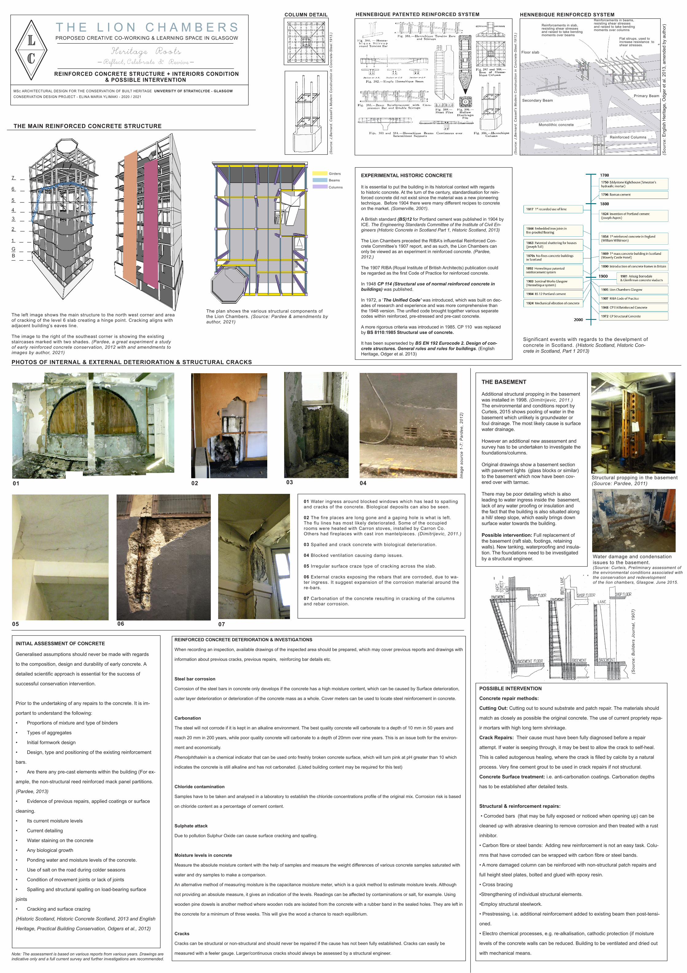
PHOTOS OF INTERNAL & EXTERNAL DETERIORATION & STRUCTURAL CRACKS
01 02 03 04
05 06 07
01 Water ingress around blocked windows which has lead to spalling and cracks of the concrete. Biological deposits can also be seen.
02 The fire places are long gone and a gaping hole is what is left. The flu lines has most likely deteriorated. Some of the occupied rooms were heated with Carron stoves, installed by Carron Co. Others had fireplaces with cast iron mantelpieces. (Dimitrijevic, 2011.)
03 Spalled and crack concrete with biological deterioration.
04 Blocked ventilation causing damp issues.
05 Irregular surface craze type of cracking across the slab.
06 External cracks exposing the rebars that are corroded, due to wa-ter ingress. It suggest expansion of the corrosion material around the re-bars.
07 Carbonation of the concrete resulting in cracking of the columns and rebar corrosion.
& POSSIBLE INTERVENTION
The left image shows the main structure to the north west corner and area of cracking of the level 6 slab creating a hinge point. Cracking aligns with adjacent building’s eaves line.
The image to the right of the southeast corner is showing the existing staircases marked with two shades. (Pardee, a great experiment a study of early reinforced concrete conservation, 2012 with and amendments to images by author, 2021)
Significant events with regards to the develpment of concrete in Scotland. (Historic Scotland, Historic Con-crete in Scotland, Part 1 2013)
Structural propping in the basement (Source: Pardee, 2011)
Water damage and condensationissues to the basement.(Source: Curteis, Preliminary assessment of the environmental conditions associated with the conservation and redevelopmentof the lion chambers, Glasgow. June 2015.
Note: The assessment is based on various reports from various years. Drawings are indicative only and a full current survey and further investigations are recommended.
INITIAL ASSESSMENT OF CONCRETE
Generalised assumptions should never be made with regards
to the composition, design and durability of early concrete. A
detailed scientific approach is essential for the success of
successful conservation intervention.
Prior to the undertaking of any repairs to the concrete. It is im-
portant to understand the following:
• Proportions of mixture and type of binders
• Types of aggregates
• Initial formwork design
• Design, type and positioning of the existing reinforcement
bars.
• Are there any pre-cast elements within the building (For ex-
ample, the non-structural reed reinforced mack panel partitions.
(Pardee, 2013)
• Evidence of previous repairs, applied coatings or surface
cleaning.
• Its current moisture levels
• Current detailing
• Water staining on the concrete
• Any biological growth
• Ponding water and moisture levels of the concrete.
• Use of salt on the road during colder seasons
• Condition of movement joints or lack of joints
• Spalling and structural spalling on load-bearing surface
joints
• Cracking and surface crazing
(Historic Scotland, Historic Concrete Scotland, 2013 and English
Heritage, Practical Building Conservation, Odgers et al., 2012)
REINFORCED CONCRETE DETERIORATION & INVESTIGATIONS
When recording an inspection, available drawings of the inspected area should be prepared, which may cover previous reports and drawings with
information about previous cracks, previous repairs, reinforcing bar details etc.
Steel bar corrosion
Corrosion of the steel bars in concrete only develops if the concrete has a high moisture content, which can be caused by Surface deterioration,
outer layer deterioration or deterioration of the concrete mass as a whole. Cover meters can be used to locate steel reinforcement in concrete.
Carbonation
The steel will not corrode if it is kept in an alkaline environment. The best quality concrete will carbonate to a depth of 10 mm in 50 years and
reach 20 mm in 200 years, while poor quality concrete will carbonate to a depth of 20mm over nine years. This is an issue both for the environ-
ment and economically.
Phenolphthalein is a chemical indicator that can be used onto freshly broken concrete surface, which will turn pink at pH greater than 10 which
indicates the concrete is still alkaline and has not carbonated. (Listed building content may be required for this test)
Chloride contamination
Samples have to be taken and analysed in a laboratory to establish the chloride concentrations profile of the original mix. Corrosion risk is based
on chloride content as a percentage of cement content.
Sulphate attack
Due to pollution Sulphur Oxide can cause surface cracking and spalling.
Moisture levels in concrete
Measure the absolute moisture content with the help of samples and measure the weight differences of various concrete samples saturated with
water and dry samples to make a comparison.
An alternative method of measuring moisture is the capacitance moisture meter, which is a quick method to estimate moisture levels. Although
not providing an absolute measure, it gives an indication of the levels. Readings can be affected by contaminations or salt, for example. Using
wooden pine dowels is another method where wooden rods are isolated from the concrete with a rubber band in the sealed holes. They are left in
the concrete for a minimum of three weeks. This will give the wood a chance to reach equilibrium.
Cracks
Cracks can be structural or non-structural and should never be repaired if the cause has not been fully established. Cracks can easily be
measured with a feeler gauge. Larger/continuous cracks should always be assessed by a structural engineer.
POSSIBLE INTERVENTION
Concrete repair methods:
Cutting Out: Cutting out to sound substrate and patch repair. The materials should
match as closely as possible the original concrete. The use of current propriety repa-
ir mortars with high long term shrinkage.
Crack Repairs: Their cause must have been fully diagnosed before a repair
attempt. If water is seeping through, it may be best to allow the crack to self-heal.
This is called autogenous healing, where the crack is filled by calcite by a natural
process. Very fine cement grout to be used in crack repairs if not structural.
Concrete Surface treatment: i.e. anti-carbonation coatings. Carbonation depths
has to be established after detailed tests.
Structural & reinforcement repairs:
• Corroded bars (that may be fully exposed or noticed when opening up) can be
cleaned up with abrasive cleaning to remove corrosion and then treated with a rust
inhibitor.
• Carbon fibre or steel bands: Adding new reinforcement is not an easy task. Colu-
mns that have corroded can be wrapped with carbon fibre or steel bands.
• A more damaged column can be reinforced with non-structural patch repairs and
full height steel plates, bolted and glued with epoxy resin.
• Cross bracing
•Strengthening of individual structural elements.
•Employ structural steelwork.
• Prestressing, i.e. additional reinforcement added to existing beam then post-tensi-
oned.
• Electro chemical processes, e.g. re-alkalisation, cathodic protection (if moisture
levels of the concrete walls can be reduced. Building to be ventilated and dried out
with mechanical means.
Imag
e so
urce
1-7
: Par
dee,
201
2)
(Sou
rce:
J,B
erna
rd. C
asse
ll’s
Mod
ern
Con
stru
ctio
n in
Con
cret
e-S
teel
.191
3.)
(Sou
rce:
Bui
lder
s Jo
urna
l, 19
07)
(Sou
rce:
Eng
lish
Her
itage
, Odg
er e
t al.
2013
, am
ende
d by
aut
hor)
HENNEBIQUE PATENTED REINFORCED SYSTEM
Reinforced Columns
Primary Beam
Floor slab
Secondary Beam
Monolithic concrete
Reinforcements in slab, resisting shear stresses and raised to take bending moments over beams
Reinforcements in beams, resisting shear stresses and raised to take bending moments over columns
Flat stirups, used to increase resistance to shear stresses.
COLUMN DETAIL
(Sou
rce:
J,B
erna
rd. C
asse
ll’s
Mod
ern
Con
stru
ctio
n in
Con
cret
e-S
teel
.191
3.)