Embed Size (px)
Citation preview
1
Blandine Laurenty in completion of the requirements for the Master of Science degree in Nuclear Engineering of the University of California Berkeley
The LM-LS experiment: investigating corrosion control, in Liquid Fluoride Salts, by Liquid alkali Metal Report UCBTH-06-002 Research Advisor: Professor Per F. Peterson Academic Advisor: Professor Brian D. Wirth January 2006
2
Introduction The conceptual association of liquid fluoride salts and nuclear power is as old as the civilian use of nuclear energy: in 1947 the Aircraft Reactor Experiment (ARE) development program proposed their use as a reactor fuel and coolant. However, in the 1970s, the Atomic Energy Commission abandoned the promising Molten Salt Breeder Reactor (MSBR) project at Oak Ridge National Laboratory to focus breeder reactor research efforts on the Liquid Metal Breeder (LMBR) concept. The molten salts’ attractive features were quickly forgotten, and they today are more famous for the severe corrosion issues which their use entails under certain conditions.
Composed of the most electronegative element (fluorine), and combinations of some very electropositive elements (lithium, beryllium, sodium, potassium, rubidium …) the salts involved are extremely stable compounds. The pure salts do not have the strong corroding power of water, because the products of salt corrosion (metallic fluorides), are less stable than the beryllium and alkali fluorides of the salt, whereas metallic oxides from water corrosion can be very stable. Yet, purity is not a realistic state of operation since contaminants can be introduced in the system via a variety of means including an initially impure salt charge, fluxing of the oxide film that the piping will invariably have, and ingress of impurities such as moisture or air due to a failure in the salt containment. If no control of corrosion is provided, these impurities can lead to severe attack of the structures in contact with the salt. This process is aggravated by the solubility of the corrosion products in the liquid salt. Solubility being temperature-dependant, the temperature gradient intrinsic to any heat exchanging loop transforms this corrosion equilibrium into a permanent transient: material is continuously dissolved away from the hot part of the loop and deposited in its cold part.
Interest in fluoride salts has recently revived due to the growing momentum gathered by high-temperature applications of nuclear reactors. Molten fluoride salts are stable at atmospheric pressure in a broad range of temperatures (~400°C to 1200°C) and are resistant to radiation. They have low vapour pressures and good heat transfer properties. These qualities make them attractive as high temperature reactor coolants or intermediate heat transfer agents, especially when compared to the proposed alternatives (helium or water), which would require hazardous and power-consuming compression or pressurization. Molten salts could also prove useful as a liquid blanket wall to attenuate the blast resulting from the fusion of deuterium and tritium targets in an inertial confinement fusion (ICF) chamber, and to absorb part of the fusion energy to be converted to electricity. UC Berkeley is interested in studying molten salts for use as a non-fuel liquid coolant in the Advanced High Temperature Reactor (AHTR) and as a heat transfer fluid for the intermediate heat transfer loop aiming at hydrogen production in the Next Generation Nuclear Plant (NGNP) [1]. These studies consist primarily in evaluating the efficiency of the heat transfers involved, and proposing methods to control corrosion. Meanwhile, the potential safety benefits that could result from the use of fluoride salts in the NGNP will be assessed, with respect to the presence in the hydrogen production plant of hot, pressurized and concentrated sulphuric acid and di-iodine. Another project consists in evaluating the oxygen chemistry of the proposed salt (2LiF – BeF2 also known as Flibe) for the ICF liquid wall.
3
This report will detail possible approaches to corrosion and redox potential control in fluoride salts. Specific focus will be set on the KF-LiF-NaF eutectic (Flinak), one candidate salt for the NGNP intermediate loop. After summarizing some of the lessons learned from the Molten Salt Reactor Experiment (MSRE) which ran from 1965 to 1969, the requirements set by the NGNP will be detailed. In a third part, the Fluorine potential will be defined as the main variable to describe the chemistry of this system. The thermodynamics of the corrosion process will be explained and the experiment put together to investigate some of the unknowns involved in this study will be described. A fourth part will set forth ideas to mitigate oxygen and sulphur ingress in the loop. Finally, the report will describe what remains to be understood and will propose means to move forward from the present situation to the demonstration of the feasibility of fluoride salt use as heat exchanger fluids for high-temperature applications. Note: the terms of molten salts or liquid salts will be equally used to describe the fluid here studied.
4
Table of Contents Introduction 2 I. The chemistry of fluoride salts, as learned from the MSRE..................................... 6
A. Choice of molten salts: features to be considered in a nuclear system .......................... 6 B. Definition and control of redox conditions in molten fluoride salts .............................. 8 C. Developing Breeder Reactors: the Molten Salt concept lost to the Liquid Metal
approach ....................................................................................................................... 13 D. Corrosion mechanisms in molten fluoride salts ........................................................... 15 E. Oxide, sulphide and fluoride chemistry: salt preparation ............................................ 18 F. Components and materials development...................................................................... 20
II. The New Generation Nuclear Plant (NGNP) project ................................................... 22
A. Nuclear energy to produce hydrogen and electricity ................................................... 22 B. Using a fluoride salt as the heat transfer agent............................................................. 23 C. Safety, cost-effectiveness and resulting constraints ..................................................... 25 D. Systematic approaches to salt cleaning ........................................................................ 27
III. Fluorine potential control................................................................................................. 28
A. Assessing the extent of reactions by use of thermodynamical tools ............................ 28 B. Proposed control systems ............................................................................................. 28
a. Dissolution of multi-valent fluoride salts................................................................. 28 b. Contacting the salt with a reducing metal: local and permanent method................. 30
i. Examples of rejected candidates: Al and Ti......................................................... 30 ii. A well-known and potentially effective option: liquid alkali baths ..................... 31 iii. Solubility of a reducing metal in the fluoride salt ............................................ 33
IV. Oxygen, Iodine and Sulfur ingress control................................................................... 35
A. Sources of contamination ............................................................................................. 35 B. Suggestions to segregate them out of the system......................................................... 35 C. Proposition to both clean the salt of ingress impurities and keep the fluorine potential
low: the LM-LS method ............................................................................................... 41 V. An experiment to assess the feasibility of the LM-LS method. ................................. 43
A. The LM-LS experiment: no useful result but a methodology to be partially corrected, and implemented .................................................................................................................. 43 B. Suggested methods to analyze the melts ...................................................................... 48
i. pH measurement................................................................................................... 48 ii. H2 volume measurement ...................................................................................... 48
C. What needs to be done beyond the LM-LS Experiment .............................................. 49 i. Assess the capacity for HF and heat production .................................................. 49 ii. Assess the RE solubilities and oxide stabilities ................................................... 49 iii. Thermal hydraulics........................................................................................... 50 iv. Alloys ............................................................................................................... 50 v. Tritium.................................................................................................................. 52 vi. SiC.................................................................................................................... 52
5
D. Proposed designs to clean the salt ................................................................................ 53 i. Contamination of the chemical plant by the salt – or the opposite? .................... 53 ii. Initial salt cleaning and charge............................................................................. 53 iii. Detection systems............................................................................................. 53 iv. Solid cryolite and liquid alkali metal ............................................................... 54
E. Safety assessment of the intermediate heat exchanging loop ...................................... 55 F. A few words on the Advanced High Temperature Reactor ......................................... 55
Conclusion .............................................................................................................................. 57 Appendices ............................................................................................................................. 58
Appendix 1: General properties of molten salts………………………………………60 Appendix 2: Production of Hydrogen………………………………………………...61 Appendix 3: Flinak preparation – literature review………………………………….. 62 Appendix 3b: LM-LS experiment procedure ……………………………………….67 Appendix 4: Insights on Na loops operation………………………………………….80 Appendix 5: Contacts ………………………………………………………………...81 Appendix 6: How to make purchases at UCB – procedure and some vendors which we
selected …………………………………………………………………...83 Acknowledgements ............................................................................................................... 91
6
I. The chemistry of fluoride salts, as learned from the MSRE
A. Choice of molten salts: features to be considered in a nuclear system
To choose the molten salt appropriate to the use looked for, their following features are screened [2]: properties at high temperature, likely corrosion (assessed via thermodynamical projections), and, if needed, neutronic properties. Heat transfer The fluid shall
- be compatible with construction materials, - have no violent reaction with air and/or water, - be inexpensive, - have good heat transfer properties, - melt at a temperature suitable for the process looked for, - ideally – be easily separable and recoverable in the event of a spill/leak.
Five applications made, make or would make use of molten salts as heat transfer fluids: - Advanced High Temperature Reactor (AHTR, solid fuel or fuel salt) - Salt cooled fast reactors - Molten Salt Reactors (MSR) - Fusion (liquid blanket, or cooling of a solid blanket) - Solar power towers.
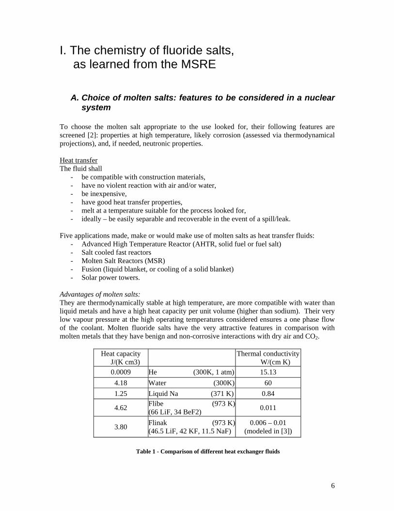
Advantages of molten salts: They are thermodynamically stable at high temperature, are more compatible with water than liquid metals and have a high heat capacity per unit volume (higher than sodium). Their very low vapour pressure at the high operating temperatures considered ensures a one phase flow of the coolant. Molten fluoride salts have the very attractive features in comparison with molten metals that they have benign and non-corrosive interactions with dry air and CO2.
Table 1 - Comparison of different heat exchanger fluids
Heat capacity J/(K cm3) Thermal conductivity
W/(cm K) 0.0009 He (300K, 1 atm) 15.13 4.18 Water (300K) 60 1.25 Liquid Na (371 K) 0.84
4.62 Flibe (973 K) (66 LiF, 34 BeF2) 0.011
3.80 Flinak (973 K) (46.5 LiF, 42 KF, 11.5 NaF)
0.006 – 0.01 (modeled in [3])
7
Cons: Their relatively high freezing point (450°C for Flibe, 455°C for Flinak vs. 98°C for Na) may lead to the plugging of conducts, and will require provisions to be made for a large heating system to reload the reactor after the salt has been discharged. They have lower thermal conductivity than Na. Moreover, the (although slow) reaction that they have with water will promote the corrosion of the structural metals [2]. In core coolants/fuels The fluid chosen shall
- have low capture cross sections for neutrons typical of the expected energy spectrum, - dissolve more than the critical concentration of fissionable material (and high
concentrations of the fertile material if a breeder scheme is pursued) at temperatures below that where the salt leaves the heat exchanger,
- be thermally stable and have low vapour pressure over the range of temperature of interest,
- have heat transfer and hydrodynamic properties compatible with efficient heat transfer, - be non aggressive to construction and moderator materials, - be stable towards radiation and handle fission products accumulation, - ensure a low fuel cycle cost (if used as reactor fuel, they should be compatible with
economical schemes for recovering the fissile and [if appropriate], bread materials, and for getting rid of the fission products).
The only elements and isotopes aside from the actinides with low enough thermal neutron capture cross sections to serve as major constituents of a Molten Salt Breeder Reactor (MSBR) are Be, Bi, 11B, C, D, F, 7Li, 15N and O. However, since C, N and O form high melting binaries with fissionable and fertile elements, and since oxygenated anions either lack the required thermal stability (e.g: NO3
- or NO2-) or
fail as solvents for high concentrations of Th (e.g. CO32-) – the only suitable salts appear to be
the fluorides [6]. Moreover, Li, Be, Th, Pa, U and Pu (these last four being of concern in fuel-bearing salts) all form fluorides which are considerably more stable than those of the structural metals Cr, Fe, Ni and Mo. This means that the fuel constituents will not react with these metals to appreciable extent, and are less likely to do so with alloys containing those metals. When UF3 – UF4 fuel is dissolved in the salt (as was in the MSRE), the attack of the Ni-based alloy used in the circulating salt system is minimized to the point of being tolerable [7]. The salt also acts as a first barrier for fission gas release: noble gases, sulphur and iodine are reported to be soluble in mixtures of molten salts (chapter 3 of [8]). Their stability in high temperature and high radiation environments, and their absence of reaction with graphite (proposed core moderator for the Advanced Nuclear Reactor (AHTR), used in the MSRE) also contribute to making them prime candidate for the core coolant of the AHTR.
8
Chlorides shall not be used in reactor cores because they are easily reduced (and thus corrosive), are volatile (AlCl3, ZrCl4, HfCl4, BeCl2) [6] and have a high absorption cross-section (generating the long lived 36Cl). The chemical inertness and low pressure of these coolants eliminate the potential for damage of the confinement structure by rapid chemical energy release (e.g. sodium) or coolant vaporization (e.g. water). Their high freezing point1 , often deemed a handicap, can be considered as an additional safety feature since coolant leaks become impossible.
B. Definition and control of redox conditions in molten fluoride salts
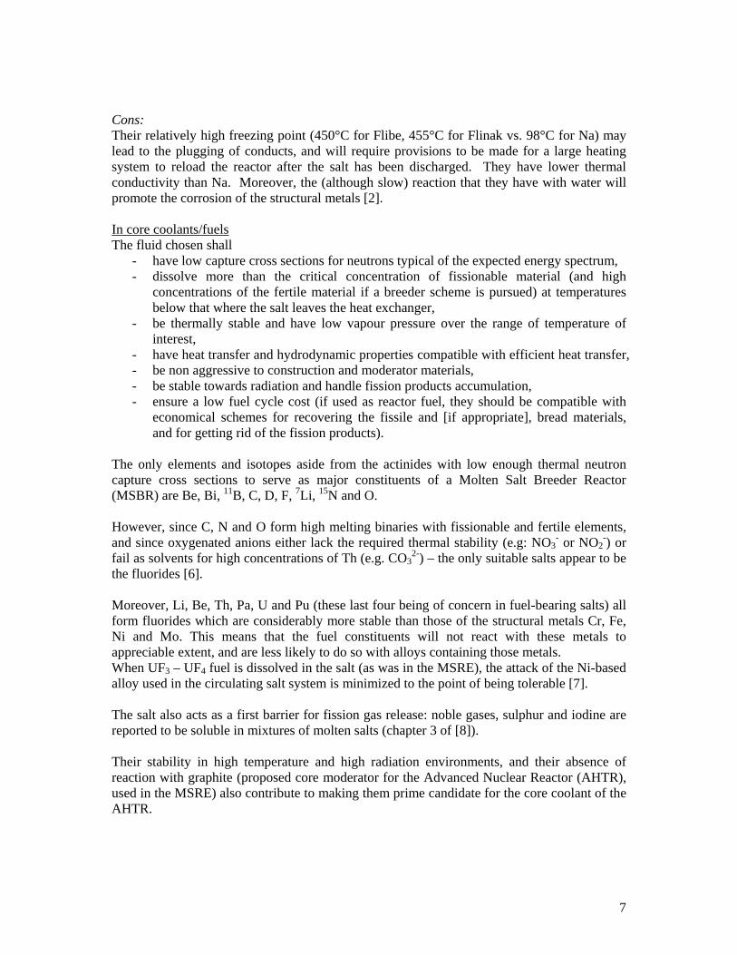
Corrosion refers to the degradation of a material due to contact with an oxidizing chemical. It occurs by the change in the oxidation state of the attacked element. Its impact can be evaluated using thermodynamic equilibriums calculations, since the attack of the material at a given temperature will only be favoured if the oxidation products are more stable than the initial species. In this respect, electrochemical tools and thermodynamical calculations can be equivalently used to reach this goal, given that this is equivalently described by the Nernst equation, or by free energy (∆G) comparisons: Oxidation semi-equation:
M = Mz+ + ze- εΜ = εΜ ° - RT/(zFe) . ln (a[Mz+]/a[M]) ,
where ε ° = - ∆G° / F . z F=e.NA is the Faraday constant 2 and a[Z] = γ[Ζ].[Z] the activity of species Z in the melt,
whose activity coefficient is γ[Ζ] and concentration is [Z].
So that a species be oxidized (lose electrons), another one has to be reduced (gain electrons). Using for the purpose of illustration the simple case where the two equations’ stoechiometries are identical, Nz+ + ze-= N where εΝ = εΝ ° - RT/(zFe) . ln (a[Nz+]/a[N]) Therefore, the redox equation Nz+ + M = N + Mz+
can be described with the Nernst potential ε = εΜ − εΝ
from which we can obtain ∆Gox = - ε . F . z Since the thermodynamical constant of reaction K = exp (-∆G / RT) will quantify the extent of the reaction of oxidation of M (the higher K, the more displaced towards the formation of Mz+ will be the reaction), the smaller (i.e. the more negative and the less positive) ε is, the lesser will be the extent of M oxidation. Equivalently, the bigger the ∆G (the more positive), the lesser the corrosion of M-based alloys. Comparing the ∆G° (free energies of formation) of the fluoride compounds involved will therefore provide us with some insight as to how thermodynamically favored the attack of a
1 350°C for LiF-BeF2-NaF, 459°C for Flibe, 455°C for Flinak 2 with this sign convention, the most noble metals (Au, Cu, Ni) have the most negative ε °.
9
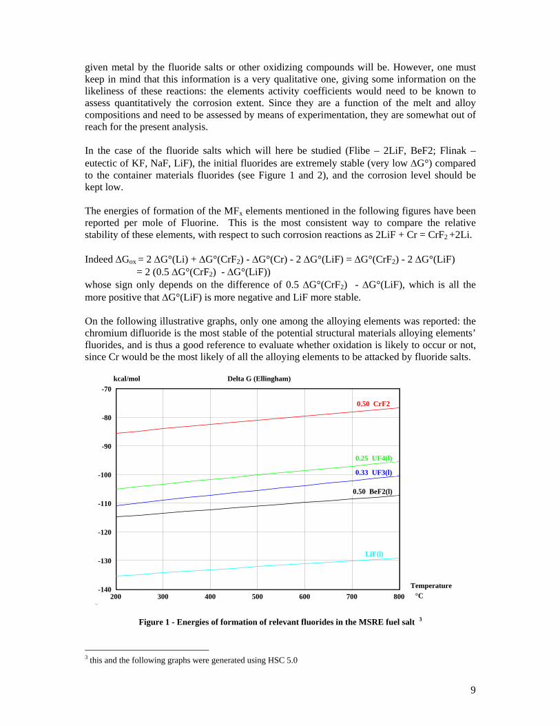
given metal by the fluoride salts or other oxidizing compounds will be. However, one must keep in mind that this information is a very qualitative one, giving some information on the likeliness of these reactions: the elements activity coefficients would need to be known to assess quantitatively the corrosion extent. Since they are a function of the melt and alloy compositions and need to be assessed by means of experimentation, they are somewhat out of reach for the present analysis. In the case of the fluoride salts which will here be studied (Flibe – 2LiF, BeF2; Flinak – eutectic of KF, NaF, LiF), the initial fluorides are extremely stable (very low ∆G°) compared to the container materials fluorides (see Figure 1 and 2), and the corrosion level should be kept low. The energies of formation of the MFx elements mentioned in the following figures have been reported per mole of Fluorine. This is the most consistent way to compare the relative stability of these elements, with respect to such corrosion reactions as 2LiF + Cr = CrF2 +2Li. Indeed ∆Gox = 2 ∆G°(Li) + ∆G°(CrF2) - ∆G°(Cr) - 2 ∆G°(LiF) = ∆G°(CrF2) - 2 ∆G°(LiF) = 2 (0.5 ∆G°(CrF2) - ∆G°(LiF)) whose sign only depends on the difference of 0.5 ∆G°(CrF2) - ∆G°(LiF), which is all the more positive that ∆G°(LiF) is more negative and LiF more stable. On the following illustrative graphs, only one among the alloying elements was reported: the chromium difluoride is the most stable of the potential structural materials alloying elements’ fluorides, and is thus a good reference to evaluate whether oxidation is likely to occur or not, since Cr would be the most likely of all the alloying elements to be attacked by fluoride salts.
Figure 1 - Energies of formation of relevant fluorides in the MSRE fuel salt 3 3 this and the following graphs were generated using HSC 5.0
200 300 400 500 600 700 800-140
-130
-120
-110
-100
-90
-80
-70Delta G (Ellingham)
Fil°C
kcal/mol
Temperature
0.50 BeF2(l)
0.33 UF3(l)
0.25 UF4(l)
LiF(l)
0.50 CrF2
10
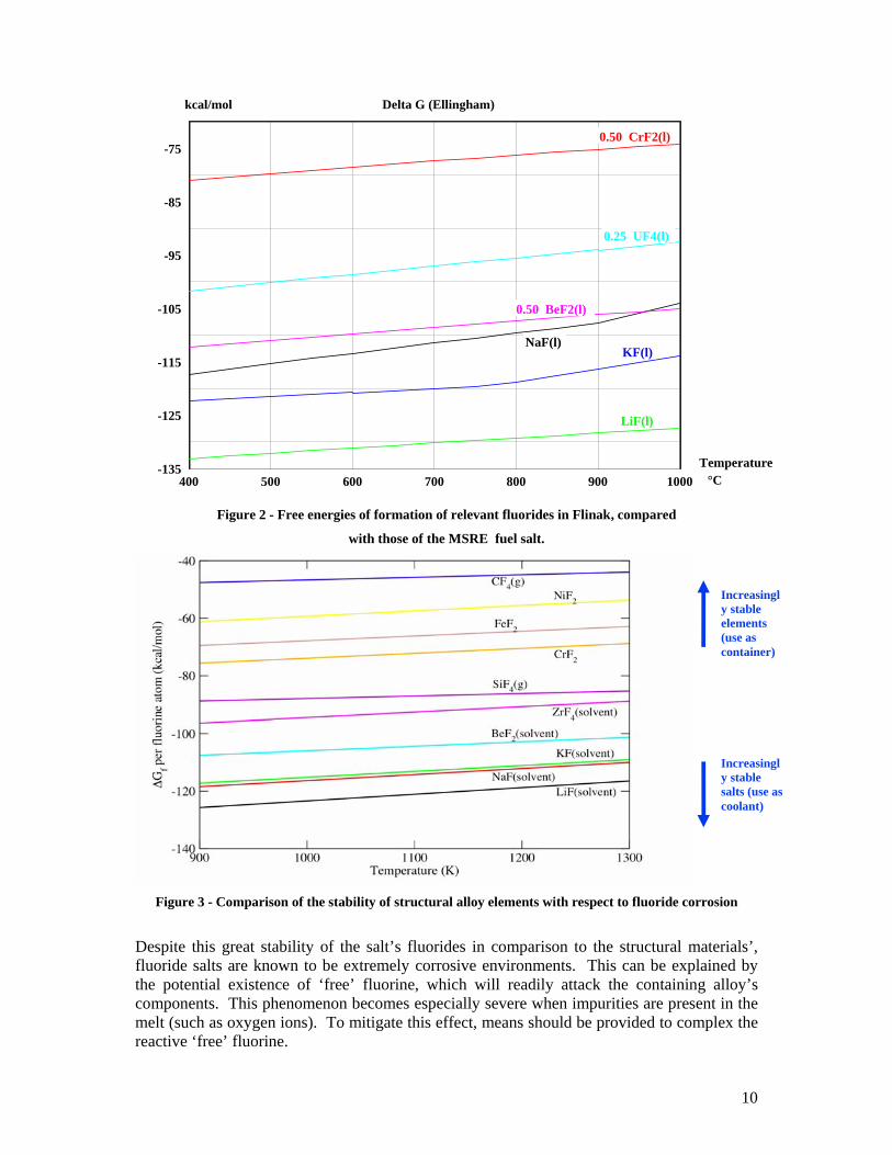
Figure 2 - Free energies of formation of relevant fluorides in Flinak, compared
with those of the MSRE fuel salt.
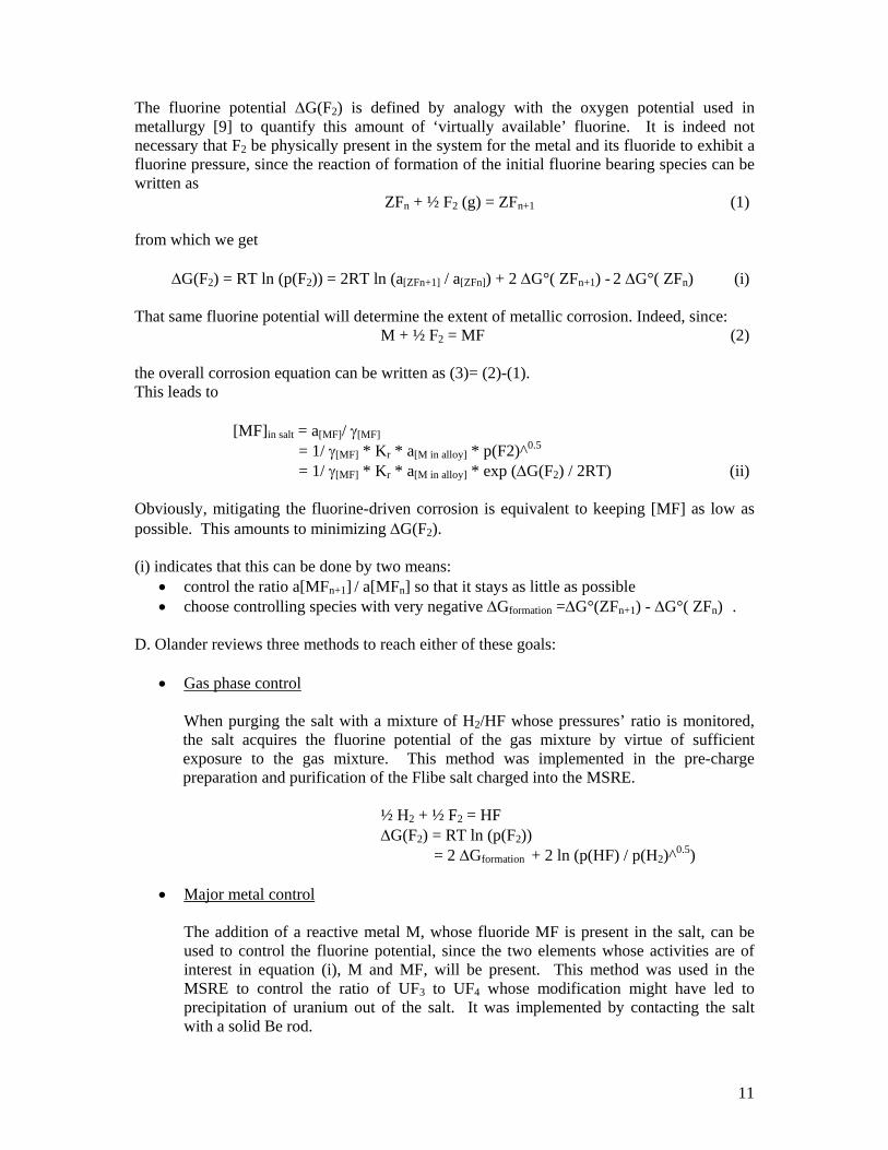
Figure 3 - Comparison of the stability of structural alloy elements with respect to fluoride corrosion
Despite this great stability of the salt’s fluorides in comparison to the structural materials’, fluoride salts are known to be extremely corrosive environments. This can be explained by the potential existence of ‘free’ fluorine, which will readily attack the containing alloy’s components. This phenomenon becomes especially severe when impurities are present in the melt (such as oxygen ions). To mitigate this effect, means should be provided to complex the reactive ‘free’ fluorine.
400 500 600 700 800 900 1000-135
-125
-115
-105
-95
-85
-75
Delta G (Ellingham)
File:°C
kcal/mol
Temperature
NaF(l)KF(l)
LiF(l)
0.25 UF4(l)
0.50 CrF2(l)
0.50 BeF2(l)
Increasingly stable salts (use as coolant)
Increasingly stable elements (use as container)
11
The fluorine potential ∆G(F2) is defined by analogy with the oxygen potential used in metallurgy [9] to quantify this amount of ‘virtually available’ fluorine. It is indeed not necessary that F2 be physically present in the system for the metal and its fluoride to exhibit a fluorine pressure, since the reaction of formation of the initial fluorine bearing species can be written as ZFn + ½ F2 (g) = ZFn+1 (1) from which we get ∆G(F2) = RT ln (p(F2)) = 2RT ln (a[ZFn+1] / a[ZFn]) + 2 ∆G°( ZFn+1) - 2 ∆G°( ZFn) (i) That same fluorine potential will determine the extent of metallic corrosion. Indeed, since: M + ½ F2 = MF (2) the overall corrosion equation can be written as (3)= (2)-(1). This leads to [MF]in salt = a[MF]/ γ[MF] = 1/ γ[MF] * Kr * a[M in alloy] * p(F2)^0.5 = 1/ γ[MF] * Kr * a[M in alloy] * exp (∆G(F2) / 2RT) (ii) Obviously, mitigating the fluorine-driven corrosion is equivalent to keeping [MF] as low as possible. This amounts to minimizing ∆G(F2). (i) indicates that this can be done by two means:
• control the ratio a[MFn+1] / a[MFn] so that it stays as little as possible • choose controlling species with very negative ∆Gformation =∆G°(ZFn+1) - ∆G°( ZFn) .
D. Olander reviews three methods to reach either of these goals:
• Gas phase control
When purging the salt with a mixture of H2/HF whose pressures’ ratio is monitored, the salt acquires the fluorine potential of the gas mixture by virtue of sufficient exposure to the gas mixture. This method was implemented in the pre-charge preparation and purification of the Flibe salt charged into the MSRE. ½ H2 + ½ F2 = HF ∆G(F2) = RT ln (p(F2)) = 2 ∆Gformation + 2 ln (p(HF) / p(H2)^0.5)
• Major metal control
The addition of a reactive metal M, whose fluoride MF is present in the salt, can be used to control the fluorine potential, since the two elements whose activities are of interest in equation (i), M and MF, will be present. This method was used in the MSRE to control the ratio of UF3 to UF4 whose modification might have led to precipitation of uranium out of the salt. It was implemented by contacting the salt with a solid Be rod.
12
M + ½ F2 = MF ∆G(F2) = RT ln (p(F2)) = 2 ( ∆Gformation + ln (a[MF]) ) In the case of pluri-component salts, care must be taken in the choice of the metal: it should not be so reducing as to reduce the salt’s other fluoride species M’F to M’ via: M + M’F = MF + M’
• Dissolved salt control
Fluoride salts, soluble in the fluoride melt (e.g. Flibe or Flinak), with two valence states close in energy, can be used to control the fluorine potential. The effectiveness of this approach depends on the ratio of the two valence states’ activities – and is therefore hard to assess since the activity coefficients of these solutions are not known. It proved effective in the MSRE, where the couple UF3/ UF4 controlled the fluorine potential. Dissolution of rare earths, such as Cerium (CeF3/CeF4), has been suggested in Flibe.
These three methods can be understood as providing the potentially available fluorine with targets which will be preferentially oxidized. This would deter it from attacking the structural metallic alloys whose products of corrosion are not as thermodynamically stable (when the kinetics of the reaction do not prevent it).
13
C. Developing Breeder Reactors: the Molten Salt concept lost to the Liquid Metal approach
At a time when uranium shortage was feared, breeder reactor development programs were launched to keep power costs down in the eventuality of an increase in the uranium prices. A successful breeder is one that can rationally deal with the spent core, either by achieving long burn-ups or by greatly simplifying the recycle step to recover the breeded material. Molten salts were first thought of in nuclear systems as a way to use a liquid form of fuel. The liquid form enables online chemical processing of the fuel and therefore, the continuous removal of fission products. In the 50s, ORNL concentrated on three types of liquid fuel : fuels in aqueous solution, fuels suspended in liquid (or slurries), and molten salt fuels. The aqueous reactor, fuelled with dissolved uranium sulphates, was abandoned after uranium was found to have precipitated out of the solution and subsequently molten part of the container tank [13]. A nuclear reactor fuelled by a molten salt was first suggested in 1947, to power an aircraft. The aircraft program ran from 1946 to 1961 [10], and started a 30 year period during which molten fluoride salts were studied at ORNL. The molten NaF-ZrF4-UF4 [7] salts were tested for 9 days in the Aircraft Reactor Experiment in 1954, with an output temperature of 860°C, in a reactor moderated with BeO and contained in Inconel (p 110 of [12]). Their properties were found attractive enough for a proposal to be made in 1959 for the Molten Salt Reactor Experiment (MSRE) to investigate a molten salt fuelled thermal reactor concept that might lead to the development of a thermal breeder reactor. The conclusions drawn from this later experiment were extremely optimistic: ‘The Molten Salt Breeder Reactor (MSBR) promises to combine simplified fuel recycle and stable fuel in a high performance thermal breeder having low power costs.’ [11] The MSR technology proved adequate for successful construction and operation of the MSRE which showed that circulating molten fuel is practical, that fluoride salts are stable under reactor conditions and that corrosion of the container material can be very low [12]. The MSRE ran an 8 MWth reactor. It was contained in Hastelloy N, moderated with graphite and used a mixture of UF3 and UF4 dissolved in Flibe (2LiF – BeF2) as fuel. ZrF4 was added to the salt in order to prevent precipitation of UO2 were oxygen contamination to occur.4 It was the first reactor to be made critical on U233, which happened in June 1965. Although the MSRE was shut down in 1969, and the program for the development of a molten salt breeder reactor terminated in 1976, ‘the optimism of these [ORNL research] groups [was] not confined to the MSRE, not even to the MSBR’, as Alvin M. Weinberg5 stated in February 1970 [15]. The program seems indeed not to have been abandoned because of corrosion issues as is often assumed, but because the liquid metal fast breeder reactor (LMFBR) program seemed more likely to be operational [7] in the Atomic Energy Commission’s eyes. Numerous fuel mixtures were studied in the MSRE development program, and most of their properties were then determined and tabulated: viscosity, thermal conductivity, phase
4 ZrO2 would have been the first oxide to form in this mixture. Its solubility in the fused salt is 700 ppm. However, after 4 years of operation, only extremely low oxide levels were found in the fuel – about 60 ppm in solution. Therefore, the need to add ZrF4 as a cushion to prevent the formation of UO2 disappeared. [14] 5 Director of ORNL since 1955
14
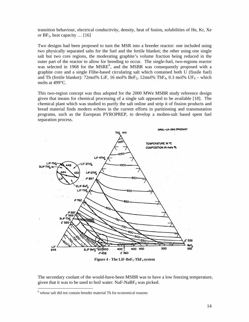
transition behaviour, electrical conductivity, density, heat of fusion, solubilities of He, Kr, Xe or BF3, heat capacity … [16] Two designs had been proposed to turn the MSR into a breeder reactor: one included using two physically separated salts for the fuel and the fertile blanket; the other using one single salt but two core regions, the moderating graphite’s volume fraction being reduced in the outer part of the reactor to allow for breeding to occur. The single-fuel, two-regions reactor was selected in 1968 for the MSRE6, and the MSBR was consequently proposed with a graphite core and a single Flibe-based circulating salt which contained both U (fissile fuel) and Th (fertile blanket): 72mol% LiF, 16 mol% BeF2, 12mol% ThF4, 0.3 mol% UF4 – which melts at 499°C. This two-region concept was thus adopted for the 2000 MWe MSBR study reference design given that means for chemical processing of a single salt appeared to be available [18]. The chemical plant which was studied to purify the salt online and strip it of fission products and bread material finds modern echoes in the current efforts in partitioning and transmutation programs, such as the European PYROPREP, to develop a molten-salt based spent fuel separation process.
Figure 4 - The LiF-BeF2-ThF4 system
The secondary coolant of the would-have-been MSBR was to have a low freezing temperature, given that it was to be used to boil water: NaF-NaBF4 was picked. 6 whose salt did not contain breeder material Th for economical reasons
15
NaBF4, which was tested as a coolant salt, is somehow problematic because the stoechiometric NaBF4 does not exist in the molten salt without a very high partial pressure of BF3 gas. Yet, one of its major advantages is that it has a high solubility of tritium, which can then be removed and isolated in the gas purge system with reduced probability of leaking to the steam producing apparatus [7].
D. Corrosion mechanisms in molten fluoride salts
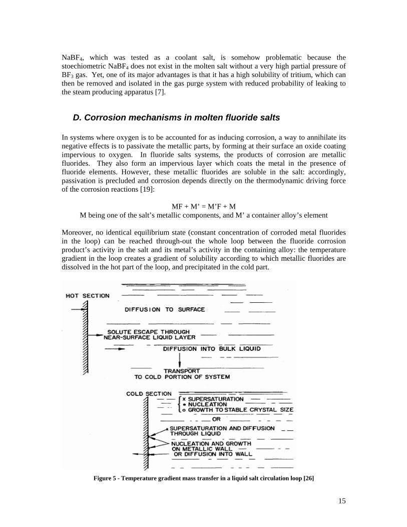
In systems where oxygen is to be accounted for as inducing corrosion, a way to annihilate its negative effects is to passivate the metallic parts, by forming at their surface an oxide coating impervious to oxygen. In fluoride salts systems, the products of corrosion are metallic fluorides. They also form an impervious layer which coats the metal in the presence of fluoride elements. However, these metallic fluorides are soluble in the salt: accordingly, passivation is precluded and corrosion depends directly on the thermodynamic driving force of the corrosion reactions [19]:
MF + M’ = M’F + M M being one of the salt’s metallic components, and M’ a container alloy’s element
Moreover, no identical equilibrium state (constant concentration of corroded metal fluorides in the loop) can be reached through-out the whole loop between the fluoride corrosion product’s activity in the salt and its metal’s activity in the containing alloy: the temperature gradient in the loop creates a gradient of solubility according to which metallic fluorides are dissolved in the hot part of the loop, and precipitated in the cold part.
Figure 5 - Temperature gradient mass transfer in a liquid salt circulation loop [26]
16
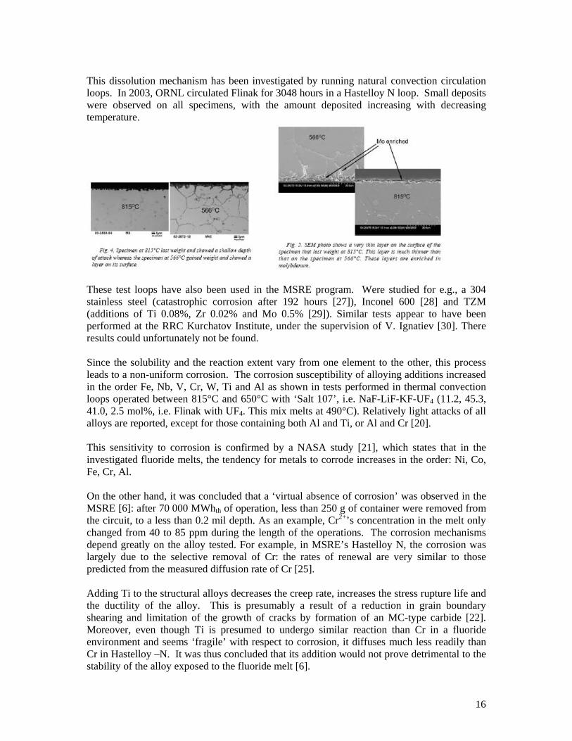
This dissolution mechanism has been investigated by running natural convection circulation loops. In 2003, ORNL circulated Flinak for 3048 hours in a Hastelloy N loop. Small deposits were observed on all specimens, with the amount deposited increasing with decreasing temperature.
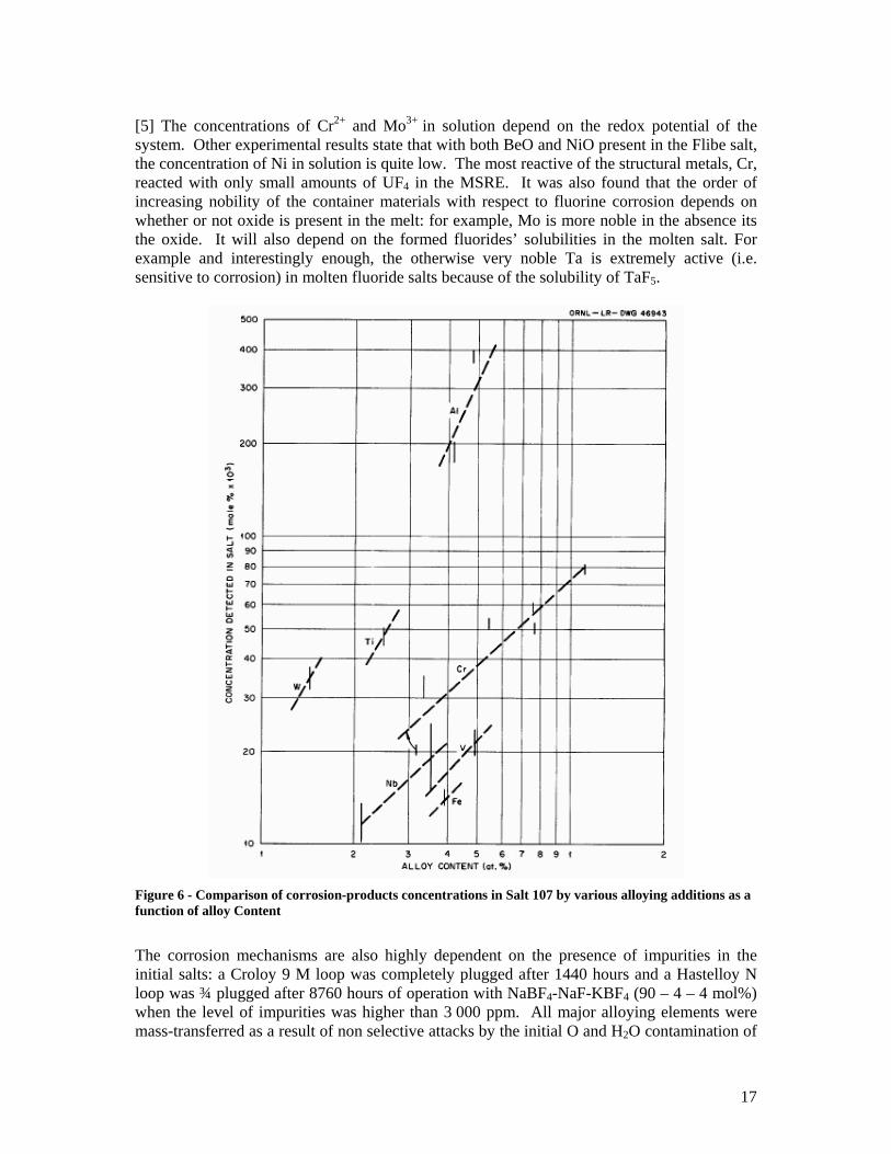
These test loops have also been used in the MSRE program. Were studied for e.g., a 304 stainless steel (catastrophic corrosion after 192 hours [27]), Inconel 600 [28] and TZM (additions of Ti 0.08%, Zr 0.02% and Mo 0.5% [29]). Similar tests appear to have been performed at the RRC Kurchatov Institute, under the supervision of V. Ignatiev [30]. There results could unfortunately not be found. Since the solubility and the reaction extent vary from one element to the other, this process leads to a non-uniform corrosion. The corrosion susceptibility of alloying additions increased in the order Fe, Nb, V, Cr, W, Ti and Al as shown in tests performed in thermal convection loops operated between 815°C and 650°C with ‘Salt 107’, i.e. NaF-LiF-KF-UF4 (11.2, 45.3, 41.0, 2.5 mol%, i.e. Flinak with UF4. This mix melts at 490°C). Relatively light attacks of all alloys are reported, except for those containing both Al and Ti, or Al and Cr [20]. This sensitivity to corrosion is confirmed by a NASA study [21], which states that in the investigated fluoride melts, the tendency for metals to corrode increases in the order: Ni, Co, Fe, Cr, Al. On the other hand, it was concluded that a ‘virtual absence of corrosion’ was observed in the MSRE [6]: after 70 000 MWhth of operation, less than 250 g of container were removed from the circuit, to a less than 0.2 mil depth. As an example, Cr2+’s concentration in the melt only changed from 40 to 85 ppm during the length of the operations. The corrosion mechanisms depend greatly on the alloy tested. For example, in MSRE’s Hastelloy N, the corrosion was largely due to the selective removal of Cr: the rates of renewal are very similar to those predicted from the measured diffusion rate of Cr [25]. Adding Ti to the structural alloys decreases the creep rate, increases the stress rupture life and the ductility of the alloy. This is presumably a result of a reduction in grain boundary shearing and limitation of the growth of cracks by formation of an MC-type carbide [22]. Moreover, even though Ti is presumed to undergo similar reaction than Cr in a fluoride environment and seems ‘fragile’ with respect to corrosion, it diffuses much less readily than Cr in Hastelloy –N. It was thus concluded that its addition would not prove detrimental to the stability of the alloy exposed to the fluoride melt [6].
17
[5] The concentrations of Cr2+ and Mo3+ in solution depend on the redox potential of the system. Other experimental results state that with both BeO and NiO present in the Flibe salt, the concentration of Ni in solution is quite low. The most reactive of the structural metals, Cr, reacted with only small amounts of UF4 in the MSRE. It was also found that the order of increasing nobility of the container materials with respect to fluorine corrosion depends on whether or not oxide is present in the melt: for example, Mo is more noble in the absence its the oxide. It will also depend on the formed fluorides’ solubilities in the molten salt. For example and interestingly enough, the otherwise very noble Ta is extremely active (i.e. sensitive to corrosion) in molten fluoride salts because of the solubility of TaF5.
Figure 6 - Comparison of corrosion-products concentrations in Salt 107 by various alloying additions as a function of alloy Content
The corrosion mechanisms are also highly dependent on the presence of impurities in the initial salts: a Croloy 9 M loop was completely plugged after 1440 hours and a Hastelloy N loop was ¾ plugged after 8760 hours of operation with NaBF4-NaF-KBF4 (90 – 4 – 4 mol%) when the level of impurities was higher than 3 000 ppm. All major alloying elements were mass-transferred as a result of non selective attacks by the initial O and H2O contamination of
18
the salt. Saturation concentrations of 700 ppm Fe and 470 ppm Cr in solution in the fluoride melt were determined for the fluoroborate salt at 460°C [24].
E. Oxide, sulphide and fluoride chemistry: salt preparation [31] About 2 700 pounds of Flibe (7LiF – 66%; BeF2 – 34%) were used in the MSRE, as fuel, coolant and flush salt. These salts were purified prior to injection in the reactor. The fluorides mixtures were sparged with HF and H2 to remove oxide 7 and sulphide impurities. They were then sparged with hydrogen alone and contacted with Be metal to reduce reductible cationic impurities. 1. Removal of oxides, sulphides and iodides So as to avoid corrosion of the MSRE reactor vessel, or deposition of solid oxide particles or scales that would hurt the heat transfer, the oxides (soluble to up to 600 ppm in 660°C Flibe [31]) were removed from the salt before its loading, via the reaction
O2- + 2HF= 2F- + H2O (gas) K = 4 105 at 600°C in Flibe [5].
This reaction was also used as an analytical tool to determine oxide concentrations at very low levels in the MSRE fluoride mixtures. The ease of oxide removal by hydrofluorination has been reported to increase with decreasing temperature and (as expected given LeChatelier’s principle) with increasing partial pressure of HF [33]. The oxide level is reported to have been lowered to 60 ppm +/- 15 ppm [5]. Sulphur attacks Ni based alloys at high-temperatures. The sulphate’s thermal decomposition products (SO3 and SO2 or H2S) are expected to form metal sulphides and oxides at process temperatures of 600 to 800°C with Ni or Cu. The sulphate ion (SO4
2-) can be reduced in a sulphide by hydrogen, and consequently removed as H2S when it reacts with HF.
2HF(g) + S2- = 2F- + H2S (g) where p(H2S) /(p²(HF) * a[S2-]) > 104 in Flibe at 600°C
A similar reaction is reported to occur with I- and could be of equal interest for the NGNP loop:
HF(g)+I- = F- + HI(g) [5]
H2S’ environmental impact can be efficiently mitigated by capture and neutralization, through industrial processes as developed, for e.g., in coal-burning plants. The sulphates can also be rapidly reduced by active metals. As in the case of HF attack on structural metals, controlling the p(H2S) / p(H2) ratio should prevent the corrosion of Ni by H2S.
7 The oxides are formed from pyrolysis of the fluoride salts with their absorbed water, when they are heated above their liquidus temperature.
19
The concurrent reaction:
M° + 2HF = MF2 + H2 must be taken into account to fix a maximum value for HF partial pressure, in order to protect the structural materials [34]. The presence of H2 reduces the corrosiveness of the HF-H2O effluent mixture, whose impact can be further reduced by lining the stainless steel containers with pure Cu or Ni. For example, to limit the concentration of NiF2 in the salt to 25 ppm, [HF] in H2 must be 38% by volume at 600°C, and 23% at 500°C. In the same way, the process temperature needs to be set as a compromise between better oxide removal (low temperature) and less corrosion (lower temperatures favour corrosion of the process equipment according to [31] p 23). 2. Removal of metallic impurities If significant concentrations of metallic fluorides that are more easily reduced than the chosen salts’ metals are present in the salt, excessive corrosion of the container is expected to occur by oxidation of the least noble of the alloy additives (for e.g., Cr oxidized to CrF2 in the Hastelloy-N8 used in the MSRE, through redox reactions such as FeF2 + Cr = Fe + CrF2). Cr, Ni and Fe fluorides are potentially significant impurities. In the MSRE, they were reduced from solution in the molten fluoride by a final gas sparge treatment with H2: while CrF2 was essentially inert to reduction for any practical purposes and FeF2 hard to reduce, NiF2 could be gotten rid of at operating temperature via the reaction:
MF2 + H2(g) = 2HF(g) + M (c) in Flibe where p²(HF)/ (p(H2) . [MF2]) = 5.5 10-6 for Cr; 0.13 for Fe, 16 000 for
Ni for the couple (MSRE fuel salt, Hastelloy-N) The final phase of the salt preparation process involved reducing the remaining potential structural metal impurities, by contacting the mix with an excess of active metal whose cation was present in the salt: Be and Zr (effective reductants for Cr, Ni and Fe) were proposed and Be used. Li was not retained because of its low density, low melting point, and incompatibility with Ni or Cu at the process temperatures. However, the reduction reactions that were to take place appeared to be non-stoechiometric, all the more that the active metals’ surfaces became coated by the reduced materials. The effectiveness of the reducing measure was further limited by the efficiency of the liquid/solid separation process. The particles suspended in the melt needed to be filtered but this proved difficult given that the suspended oxide particles in the salt mixtures rapidly plugged the sintered nickel filter. Separation of the reduced metal particles thus depended upon decantation. The last encountered problem regarded the need for process control measures: the time saved by the rapid reaction of the strong reducing agents could not be taken advantage of, given that the analytical methods used – chemical analysis –, were time consuming. Finally, this method
8 Ni based alloy, 6-8% Cr
20
implied finding a way to add the metals to the melt without exposing either of them to sources of oxide contaminants (especially air). This procedure would certainly be more efficient if a liquid metal was used instead of a solid one. 3. Operations Sparge rates greater than 10 litres/min caused frequent entrainment of the salt in the gas effluent lines ([31] p 12). Those consequently became plugged, when the entrained salt froze in them. The concentration of HF in the effluent gas was monitored to know the extent of the reduction by H2, and was determined by direct titration of a side stream with a standard caustic solution. The gas effluent was then passed through a cold trap (-12°C) to condense all of the formed H2O and most of the HF ([31] p 20) 9. The effluent HF was then trapped on NaF pellets ([31] p 21) - caustic scrubbers are traditionally used for this operation, but they would have been a source of contamination by water. To prevent condensation of HF, and stabilize the polymerization state of the gas in the Ni gas lines, the lines were traced with insulated Nichrome wire and maintained above 100°C by electrical resistance heating. H2S in the effluent gas was collected in ammoniacal cadmium chloride solutions and titrated with a standard iodine solution [31].
F. Components and materials development Although the temperature at which the NGNP will be run is higher than that used in the MSRE (550°C to 900°C for the first generation of metallic heat exchangers and 1000°C for advanced composite materials; compared to the 650°C-run MSRE), the experience acquired in developing loop components such as mechanical valves to control the salt flow, pressure relief systems and cover gas monitoring should be taken advantage of. Most of this information can be found in the ORNL reports. For e.g.:
- ORNL-TM 1855 (June 1967) details the development problems encountered when designing these components,
- ORNL-TM 1856 (May 1967) describes the development of instrumentation and control systems (for flow and pressure measurements),
- ORNL-TM 1857 (June 1967) gives an account of the MSR maintenance development,
- ORNL 4119 (July 1967) explains the off-gas system, - ORNL 4254 presents a conceptual design for a single fluid MSBR fuel salt
pump, which doses not require a salt-lubricated bearing. The then proposed freeze valves are a very interesting passive safety system which prompts the salt to be drained in case of power shortage. The valves and fuel pump bowl are air cooled (with low O-containing air to preclude lubricating oil spilling on hot surfaces to cause a fire): were the electricity supply to be lost, the cooling
9 HF boils at 19°C
21
system would be made inefficient and the salt would drain through the thawed valves.
- ORNL 4344 (February 1969) describes concepts for a bubble generator and gas separator 10 . Development work on methods for this separation are presented in ORNL 4396 (August 1969), ORNL 4548 (August 1970) and ORNL 4676 (August 1971). ORNL 4676 also includes studies of the tritium behaviour. A later report11 proposed to use natural convection of a NaK cooling system for the drain tank.
- The primary drain tank using a Flibe–to water–to air cooling system and the requirements for the MSBR salt pump test stand are covered in ORNL 4449 (February 1970).
- Descriptions of the salt pumps, off gas systems, heat exchangers, salt samplers on the fuel pump, coolant pumps and processing tanks are provided p 132 of [14].
A gamma spectrometer was tested and used to scan the primary heat exchanger, according to [12]. An equivalently non intrusive method would be required to verify that the heat exchangers are neither plugged nor leaking. An Ar electrolytic hygrometer was tested for inline monitoring of the removal of oxide from the molten salt after treatment with H2/HF [35], but did not prove practical because it could not be contacted with HF. All salt piping and vessels were electrically heated to prepare for salt filling and keep the salt molten where there was no nuclear power [36]. The He blanket used in the bowl of the fuel pump was cleaned of O2 and H2O (to a lower than 10 ppm level) by being passed through a 1200°F titanium sponge.
10 MSRE was primarily concerned by Xe-135 poisoning, which was removed by He [12] 11 ORNL 4622 Jan 1971
22
II. The New Generation Nuclear Plant (NGNP) project
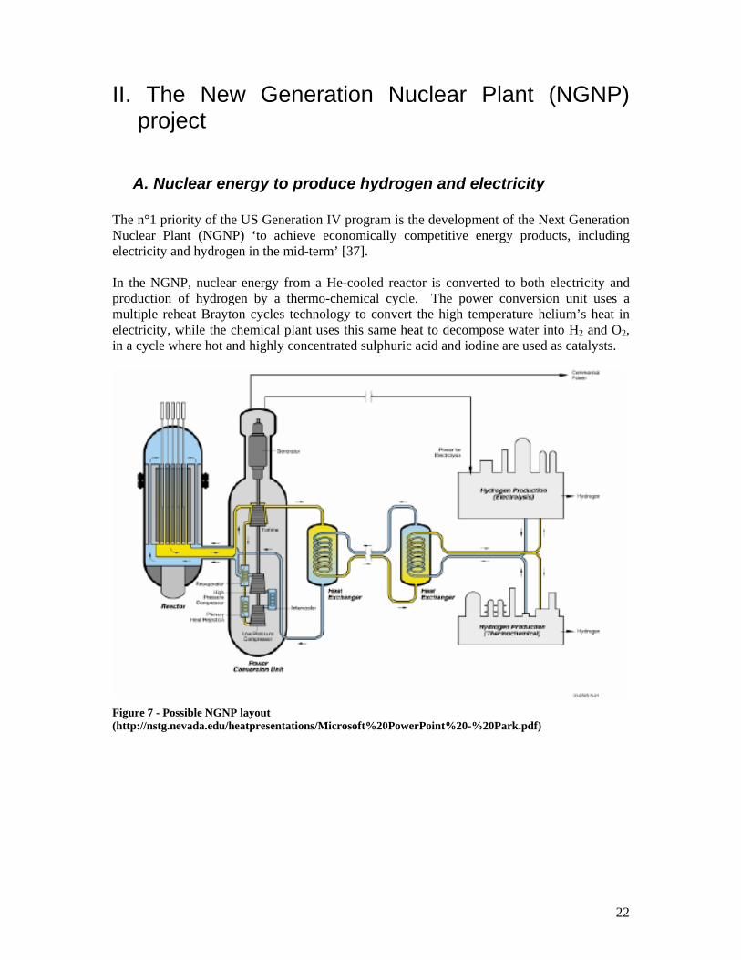
A. Nuclear energy to produce hydrogen and electricity The n°1 priority of the US Generation IV program is the development of the Next Generation Nuclear Plant (NGNP) ‘to achieve economically competitive energy products, including electricity and hydrogen in the mid-term’ [37]. In the NGNP, nuclear energy from a He-cooled reactor is converted to both electricity and production of hydrogen by a thermo-chemical cycle. The power conversion unit uses a multiple reheat Brayton cycles technology to convert the high temperature helium’s heat in electricity, while the chemical plant uses this same heat to decompose water into H2 and O2, in a cycle where hot and highly concentrated sulphuric acid and iodine are used as catalysts.
Figure 7 - Possible NGNP layout (http://nstg.nevada.edu/heatpresentations/Microsoft%20PowerPoint%20-%20Park.pdf)
23
B. Using a fluoride salt as the heat transfer agent
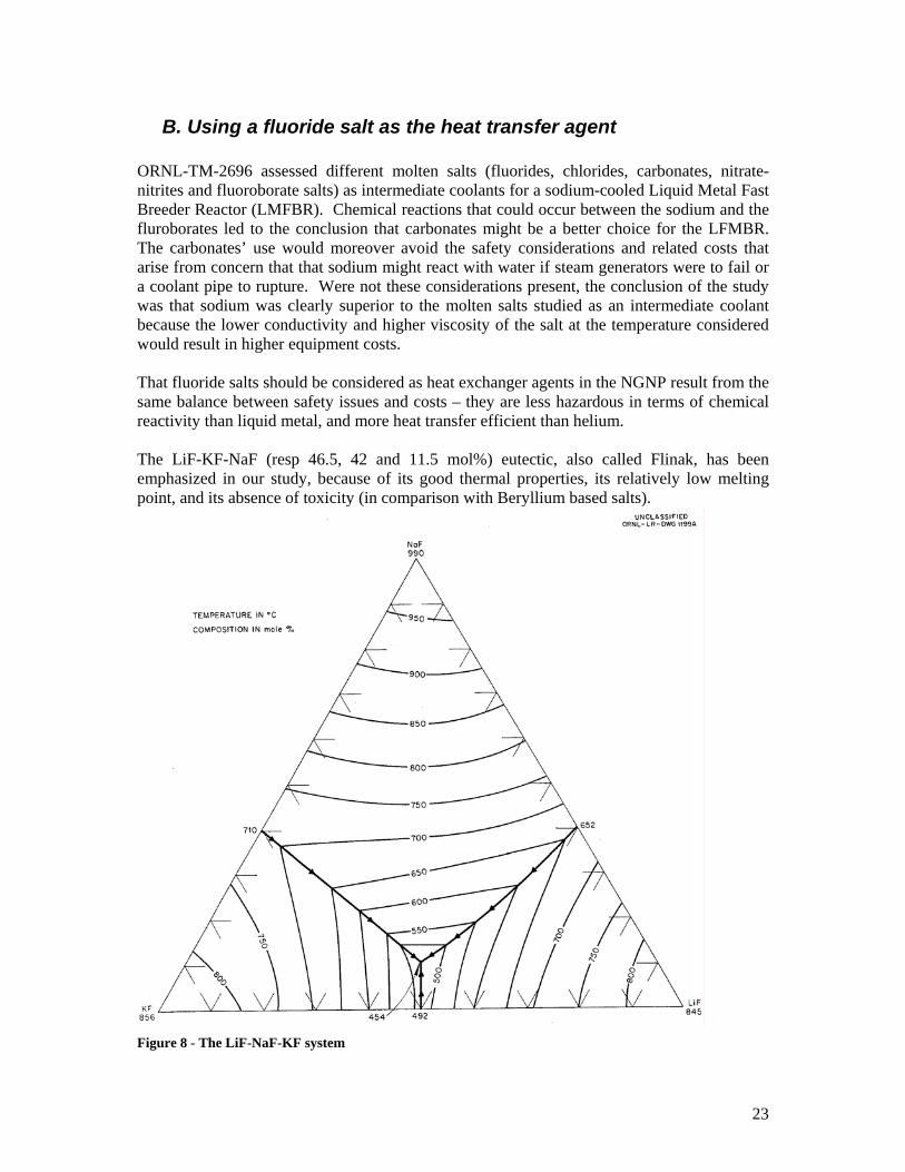
ORNL-TM-2696 assessed different molten salts (fluorides, chlorides, carbonates, nitrate-nitrites and fluoroborate salts) as intermediate coolants for a sodium-cooled Liquid Metal Fast Breeder Reactor (LMFBR). Chemical reactions that could occur between the sodium and the fluroborates led to the conclusion that carbonates might be a better choice for the LFMBR. The carbonates’ use would moreover avoid the safety considerations and related costs that arise from concern that that sodium might react with water if steam generators were to fail or a coolant pipe to rupture. Were not these considerations present, the conclusion of the study was that sodium was clearly superior to the molten salts studied as an intermediate coolant because the lower conductivity and higher viscosity of the salt at the temperature considered would result in higher equipment costs. That fluoride salts should be considered as heat exchanger agents in the NGNP result from the same balance between safety issues and costs – they are less hazardous in terms of chemical reactivity than liquid metal, and more heat transfer efficient than helium. The LiF-KF-NaF (resp 46.5, 42 and 11.5 mol%) eutectic, also called Flinak, has been emphasized in our study, because of its good thermal properties, its relatively low melting point, and its absence of toxicity (in comparison with Beryllium based salts).
Figure 8 - The LiF-NaF-KF system
24
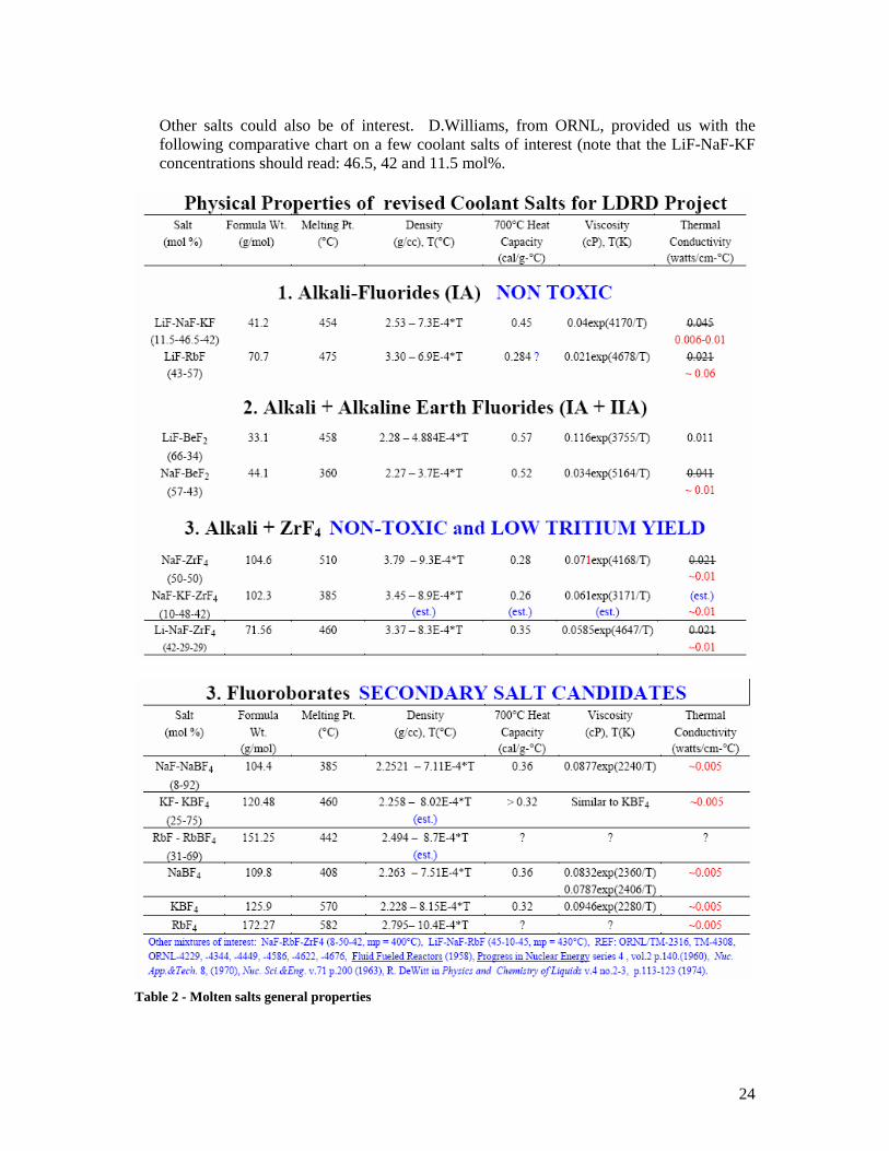
Other salts could also be of interest. D.Williams, from ORNL, provided us with the following comparative chart on a few coolant salts of interest (note that the LiF-NaF-KF concentrations should read: 46.5, 42 and 11.5 mol%.
Table 2 - Molten salts general properties
25
Most of the information found on the Flinak mixture is relative to its electrolyte properties, since it is commonly used in refractory metal electrodeposition due to its very negative cathodic limit [38]. The requirement for material compatibility is that the fluorides of the salt constituents should be more stable than fluorides of the containment materials. Thus, alkali metals are the preferred cations for salt constituents and the more noble metals (e.g. Ni) are the preferred container constituents [2]. As explained in part I, along with the thermodynamical formation data, solubility information must be considered in order to assess the salt’s potential corrosiveness. This in mind, group IA halide salts (such as Flinak) have a greater solubility for the fluorides of structural materials than the group IIA-halides – the salt’s initial purity will therefore be more important for Flinak, a member of the group I A halides. Assuming a 50 MWth heat exchanger loop between the nuclear island and the hydrogen producing plant and a temperature difference of 265°C between the cold part of the loop (550°C) and the hot part, the mass flow of helium in the reactor’s side of the heat exchanger would be 36 kg/sec, and the molten salt’s mass flow 100 kg/sec. These respectively correspond to volumetric flows of 11 m3/sec and 0.05 m3/sec [39]. Comparing the use of pressurized He and molten salts in the loop will bring the same disproportion, which yields an equivalent disproportion in the pumping power requirements, to the advantage of the molten salt system.
C. Safety, cost-effectiveness and resulting constraints
A first safety feature is to separate the nuclear and hydrogen production potential hazard sources. This can be best achieved by spatially separating the two plants. For this to be possible, an economical way must be found to carry energy between them. Electricity generated by the reactor could be this energy carrier, in which case electrolysis of water would be used to generate electricity. However, the low efficiency of energy conversion from heat to electricity on the reactor side yields a very poor energy conversion efficiency for hydrogen production when combined to the electrolysis efficiency (0.35 x 0.7 ~ 0.25). Producing hydrogen directly from nuclear heat is more attractive since efficiencies up to 0.4 to 0.5 are expected (c.f. Appendix 2). A long distance heat carrier is thus required. Of the two proposed candidates, liquid fluoride salts are in this regard much more attractive than pressurized helium: the pumping power required is much lower and therefore less capital consuming. In addition to the nuclear risk presented by the reactor, the main hazard relative to the operation of the NGNP is the potential for generation and release of toxic chemicals, especially on the hydrogen production side: tritium, HI, I2, H2SO4, SO3, SO2 and H2 (when concentrated) are or could be present in the system, leading to the formation of toxic gas plumes, to the contamination of the hydrogen production or to a possible hydrogen explosion (p63 of [4]). Two major sources of energy might lead to the rapid dispersal of these toxic chemicals: high pressure gases, and highly energetic chemical reactions. The use of a liquid as the heat transfer agent makes the first of these two hazards less likely to occur, although the reactor vessel’s high pressure boundary in the nuclear island and the
26
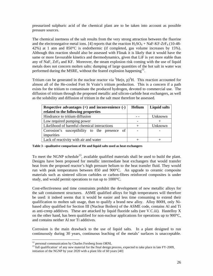
pressurized sulphuric acid of the chemical plant are to be taken into account as possible pressure sources. The chemical inertness of the salt results from the very strong attraction between the fluorine and the electronegative metal ions. [4] reports that the reaction H2SO4 + NaF-KF-ZrF4 (10-48-42%) at 1 atm and 850°C is endothermic (if completed, gas volume increases by 15%). Although this reaction should also be assessed with Flinak it is likely that it would have the same or more favourable kinetics and thermodynamics, given that LiF is yet more stable than any of NaF, ZrF4 and KF. Moreover, the steam explosion risk coming with the use of liquid metals does not concern molten salts: dumping of large quantities of the hot salt in water was performed during the MSRE, without the feared explosion happening12. Tritium can be generated in the nuclear reactor via 3He(n, p)3H. This reaction accounted for almost all of the He-cooled Fort St Vrain’s tritium production. This is a concern if a path exists for the tritium to contaminate the produced hydrogen, devoted to commercial use. The diffusion of tritium through the proposed metallic and silicon-carbide heat exchangers, as well as the solubility and diffusion of tritium in the salt must therefore be assessed.
Respective advantages (+) and inconvenience (-) related to the following properties
Helium Liquid salts
Hindrance to tritium diffusion - - Unknown Low required pumping power - + Likelihood of harmful chemical interactions + Unknown Corrosion’s susceptibility to the presence of impurities
- -
Lack of reactivity with air and water + + Table 3 - qualitative comparison of He and liquid salts used as heat exchangers
To meet the NGNP schedule13, available qualified materials shall be used to build the plant. Designs have been proposed for metallic intermediate heat exchangers that would transfer heat from the proposed reactor’s high pressure helium to the heat transfer fluid. They would run with peak temperatures between 850 and 900°C. An upgrade to ceramic composite materials such as sintered silicon carbides or carbon-fibres reinforced composites is under study, and would permit operations to run up to 1000°C. Cost-effectiveness and time constraints prohibit the development of new metallic alloys for the salt containment structures. ASME qualified alloys for high temperatures will therefore be used: it indeed seems that it would be easier and less time consuming to extend their qualification to molten salt usage, than to qualify a brand new alloy. Alloy 800H, only Ni-based alloy qualified for Section III (Nuclear Boilers) of the ASME code, contains Al and Ti as anti-creep additives. These are attacked by liquid fluoride salts (see V.C.iii). Hastelloy X on the other hand, has been qualified for non-nuclear applications for operations up to 900°C, and contains neither Al nor Ti additives. Corrosion is the main drawback to the use of liquid salts. In a plant designed to run continuously during 30 years, continuous leaching of the metals’ surfaces is unacceptable. 12 personal communication by Charles Forsberg from ORNL 13 full qualification’ of any new material for the final design process, expected to take place in late FY-2009, initiation of the NGNP by year 2020 with a plant life of 60 years [40]
27
Reducing conditions must be maintained, and monitoring systems shall be implemented. This later task will be much easier than in the case of opaque liquid-sodium14, since the molten salts are transparent to visible light. In addition to video-surveillance of the conducts, off-normal operations can be detected by gas analysis: in the case of unmitigated moisture or H2SO4 ingress, H2 and maybe some HF will be generated and can be detected. Moreover, corrosion in a fluoride salts system will be kept low if the oxide concentration is reduced. Once again, experience from the operation of liquid metal reactors can be mined from. A cold trap precipitating dissolved oxides out of the salt can be designed, given that the oxides often have melting points much higher than those of the fluorides. In a series including a 10µm filter followed by a 60µm one, the pressure rise on the second filter due to accumulation of NaOH (which precipitated more than NaO) indicated that the filters are effective – and would need to be replaced. Apart from the intrinsically specific nature of the liquid salts, a challenge arising from the use of so high temperature fluids consists in building an isolation valve that would work with high reliability on the hot leg. At high temperature, the disk and seat exposed to the flow will see their strength greatly reduced – their shock resistance therefore needs to be increased. Better materials and a new design where seat and seal are out of the flow (as in a stop valve) shall be looked for.
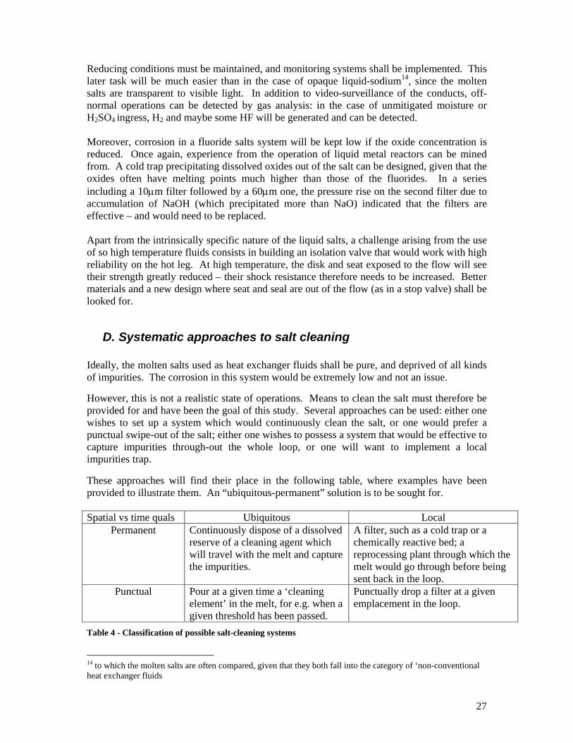
D. Systematic approaches to salt cleaning Ideally, the molten salts used as heat exchanger fluids shall be pure, and deprived of all kinds of impurities. The corrosion in this system would be extremely low and not an issue.
However, this is not a realistic state of operations. Means to clean the salt must therefore be provided for and have been the goal of this study. Several approaches can be used: either one wishes to set up a system which would continuously clean the salt, or one would prefer a punctual swipe-out of the salt; either one wishes to possess a system that would be effective to capture impurities through-out the whole loop, or one will want to implement a local impurities trap. These approaches will find their place in the following table, where examples have been provided to illustrate them. An “ubiquitous-permanent” solution is to be sought for. Spatial vs time quals Ubiquitous Local
Permanent Continuously dispose of a dissolved reserve of a cleaning agent which will travel with the melt and capture the impurities.
A filter, such as a cold trap or a chemically reactive bed; a reprocessing plant through which the melt would go through before being sent back in the loop.
Punctual Pour at a given time a ‘cleaning element’ in the melt, for e.g. when a given threshold has been passed.
Punctually drop a filter at a given emplacement in the loop.
Table 4 - Classification of possible salt-cleaning systems
14 to which the molten salts are often compared, given that they both fall into the category of ‘non-conventional heat exchanger fluids
28
III. Fluorine potential control
A. Assessing the extent of reactions by use of thermodynamical tools
To evaluate the efficiency of the below-proposed control methods, an analytical tool was sought for and found in the HSC 5.0 software. It provides calculations for thermodynamical equilibrium states, yielding the concentrations of a number of selected species depending on the species set in the input, their quantities, and the temperature selected for the equilibrium to be calculated. This software requires that activity coefficients be given for the species of interest, or that they be set to 1 by default. In molten fluoride salts, up to 5-10 mol%, the solute obeys Henry’s Law and the solvent, Raoult’s law in terms of activity coefficients – i.e. their activity coefficients are constant. [41] However, in the range of concentrations that have been of interest for us given Flinak’s composition (LiF-KF-NaF resp 46.5, 42 and 11.5 mol%), they have neither been measured nor predicted. Using the mixing enthalpies of the two-salts melts and the energies of formation of each of the compounds of interest, one might be able to approximate the activity coefficients of each of the eutectic’s components. The resulting calculation which we performed yielded activity coefficients very close to 1 - yet, these would need to be validated by experiment to be given any credit to. Therefore, in the calculations that were made, the activity coefficients were set to one. It is very likely that this will give only a very rough idea of what reactions are actually taking place in the system: at the low concentrations that the structural material elements are in the alloys concerned, their activity coefficient can significantly modify their behaviour. Moreover, it must be taken into account that the resulting calculations only give data for the thermodynamical equilibrium – that may never be reached, depending on the kinetics of the different reactions. In addition, they do not take into account geometry factors such as the fact that the fluoride melts contacts the container material only by surface contact, since the computing is performed as if all the input elements were put in a well stirred mixture.
B. Proposed control systems
a. Dissolution of multi-valent fluoride salts The thermodynamic potential for corrosion can be minimized by maintaining the salt in a reducing condition by using a redox buffer. This buffer would be responsible for capturing the free fluorine, and thus making it not available for complexing the structural alloy’s metallic elements. Electrochemical studies performed at ORNL [2, 42] indicated that suitable redox buffers can be found to minimize corrosion at very high temperatures (for e.g., Yb or V, at concentrations
29
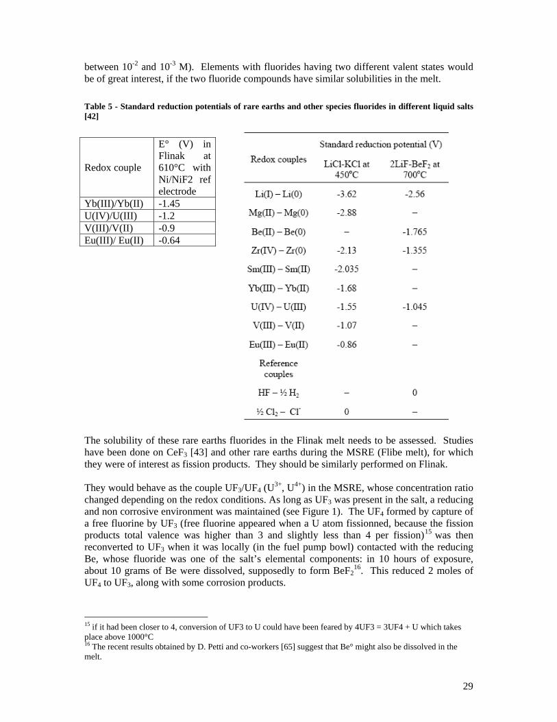
between 10-2 and 10-3 M). Elements with fluorides having two different valent states would be of great interest, if the two fluoride compounds have similar solubilities in the melt. Table 5 - Standard reduction potentials of rare earths and other species fluorides in different liquid salts [42]
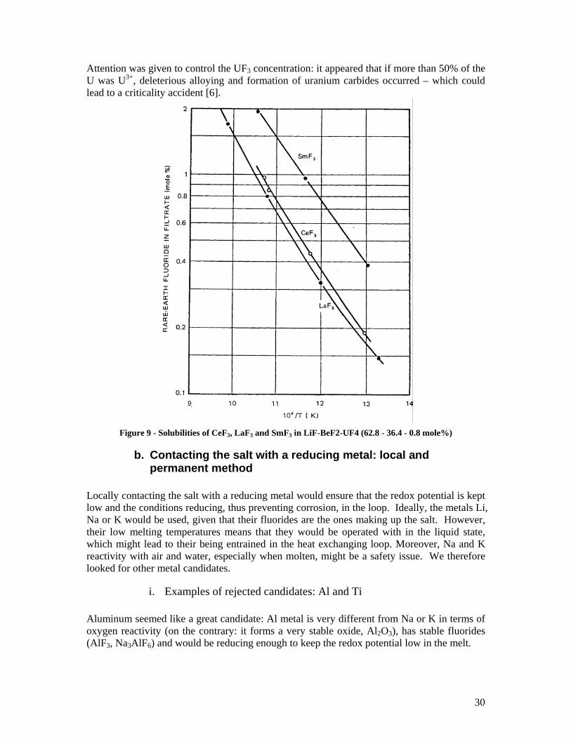
The solubility of these rare earths fluorides in the Flinak melt needs to be assessed. Studies have been done on CeF3 [43] and other rare earths during the MSRE (Flibe melt), for which they were of interest as fission products. They should be similarly performed on Flinak. They would behave as the couple UF3/UF4 (U3+, U4+) in the MSRE, whose concentration ratio changed depending on the redox conditions. As long as UF3 was present in the salt, a reducing and non corrosive environment was maintained (see Figure 1). The UF4 formed by capture of a free fluorine by UF3 (free fluorine appeared when a U atom fissionned, because the fission products total valence was higher than 3 and slightly less than 4 per fission)15 was then reconverted to UF3 when it was locally (in the fuel pump bowl) contacted with the reducing Be, whose fluoride was one of the salt’s elemental components: in 10 hours of exposure, about 10 grams of Be were dissolved, supposedly to form BeF2
16. This reduced 2 moles of UF4 to UF3, along with some corrosion products.
15 if it had been closer to 4, conversion of UF3 to U could have been feared by 4UF3 = 3UF4 + U which takes place above 1000°C 16 The recent results obtained by D. Petti and co-workers [65] suggest that Be° might also be dissolved in the melt.
Redox couple
E° (V) in Flinak at 610°C with Ni/NiF2 ref electrode
Yb(III)/Yb(II) -1.45 U(IV)/U(III) -1.2 V(III)/V(II) -0.9 Eu(III)/ Eu(II) -0.64
30
Attention was given to control the UF3 concentration: it appeared that if more than 50% of the U was U3+, deleterious alloying and formation of uranium carbides occurred – which could lead to a criticality accident [6].
Figure 9 - Solubilities of CeF3, LaF3 and SmF3 in LiF-BeF2-UF4 (62.8 - 36.4 - 0.8 mole%)
b. Contacting the salt with a reducing metal: local and permanent method
Locally contacting the salt with a reducing metal would ensure that the redox potential is kept low and the conditions reducing, thus preventing corrosion, in the loop. Ideally, the metals Li, Na or K would be used, given that their fluorides are the ones making up the salt. However, their low melting temperatures means that they would be operated with in the liquid state, which might lead to their being entrained in the heat exchanging loop. Moreover, Na and K reactivity with air and water, especially when molten, might be a safety issue. We therefore looked for other metal candidates.
i. Examples of rejected candidates: Al and Ti Aluminum seemed like a great candidate: Al metal is very different from Na or K in terms of oxygen reactivity (on the contrary: it forms a very stable oxide, Al2O3), has stable fluorides (AlF3, Na3AlF6) and would be reducing enough to keep the redox potential low in the melt.
31
However, its use would not be practical. It has a fairly low melting point (660°C 17), which is certainly higher than the loop’s lower end operating temperature (550°C) where the salt would most likely be contacted with the metal, but would not leave a large safety margin. Morevoer, if it was to be used in its solid form as a small pebbles bed for e.g., through which the salt would pass, it would quickly be inactivated: the oxygen contaminating species would react with the Al metal to form a coating of the very stable aluminium oxide, which (not like most oxides) is almost insoluble in Flinak. So this system would need to operate in the molten state (Al2O3 is insoluble in Al(l)), which means that heating has to be provided to the aluminium bed. Even though, this would not turn out as a convenient solution: as the HSC calculation shows, when Flinak is contacted with Al(l), cryolite (Na3AlF6) forms. This salt is slightly soluble in Flinak, but would precipitate out of the salt in the colder parts of the loop, thus leading to possible plugging of the very small channels heat exchangers. Moreover, since Al(l) would locally be in great excess over NaF, KF and LiF, a considerable amount of cryolite would be formed, thus significantly changing the salt’s composition which would be detrimental to its heat transfer properties, and to the predictability of its behaviour. Ti metal could also have been an interesting F (and O) fixer. It has different valence states fluoride compounds, which could be slightly soluble in the Flinak melt, and forms TiO and TiS in case of oxygen and sulphur impurities ingress. Locally contacting the melt with a solid bed of Ti thus looked promising. However, Ti’s reducing power is so high that some of the salt elements get reduced to their metal according to the HSC calculation, TiF4 is volatile and TiF3 leads to a higher fluoride potential than KF – which would facilitate corrosion instead of preventing its occurrence.
ii. A well-known and potentially effective option: liquid alkali baths
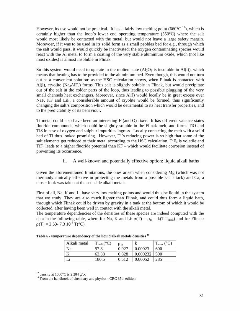
Given the aforementioned limitations, the ones arisen when considering Mg (which was not thermodynamically effective in protecting the metals from a possible salt attack) and Ca, a closer look was taken at the set aside alkali metals. First of all, Na, K and Li have very low melting points and would thus be liquid in the system that we study. They are also much lighter than Flinak, and could thus form a liquid bath, through which Flinak could be driven by gravity in a tank at the bottom of which it would be collected, after having been well in contact with the alkali metal. The temperature dependencies of the densities of these species are indeed computed with the data in the following table, where for Na, K and Li: ρ(T) = ρm – k(T-Tmelt) and for Flinak: ρ(T) = 2.53- 7.3 10-4 T(°C). Table 6 - temperature dependency of the liquid alkali metals densities 18
Alkali metal Tmelt (°C) ρm k Tmax (°C) Na 97.8 0.927 0.00023 600 K 63.38 0.828 0.000232 500 Li 180.5 0.512 0.00052 285
17 density at 1000°C is 2.284 g/cc 18 From the handbook of chemistry and physics - CRC 85th edition
32
NaF being the least stable of the liquid fluorides composing the melt (least negative energy of formation – see figure 2), it would be necessary to use Na as the reducing alkali metal, so that NaF would not be reduced to Na by either K or Li were they to be used. However, since KF is very close in energy to NaF, the exchange reaction Na (l) + KF (l) = NaF (l) + K (l) will take place, thus changing the salt’s composition and modifying its chemical and physical properties. A solution to this problem could be to use a bed of molten Na and K, whose ratio would be fixed so that it is at equilibrium with the salt’s composition – and thus would not change it. To evaluate the extent at which this reaction would take place, and thus find the appropriate ratio of K to Na in the liquid bath so as to keep the concentrations of NaF and KF equal to Flinak’s (resp 11.5 and 42%), we tried to determine the quotient of this reaction, Kr, at 550C, the expected temperature of the cold loop of the system.
Kr = exp ([- ∆Gf (Kl) – ∆Gf (NaFl) + ∆Gf(KFl) + ∆Gf(Nal)] / RT) At the chosen temperature, neither pure KF nor pure NaF can be liquid. We thus computed their energies of formation by extrapolating their known free energies (tabulated) of formation in the liquid state (at temperatures above their melting point) down to the temperature we were studying. Extrapolating from both the Ihsan Barin tables and the JANAF calculations yielded similar results: K~1 at 823K. However, we also used the formerly presented HSC software to do this calculation. The result was three orders of magnitude larger: K ~ 800 at 823 K This large discrepancy consisted in our eyes a first obstacle to the proper choice of the liquid metal mixture. Moreover, the extent to which this exchange reaction occurs being a function of the salt’s activity coefficients, it seemed that it will only be correctly assessed through experimental means – hence was born the rationale for the LM-LS experiment described in the next part. A possible way to use this system to clean the liquid salt would be to bypass all or part of the salt’s flow into a tank where it would be showered over a bed of liquid metal through which it would be driven by gravity, and at the bottom of which it would be collected to be reinjected in the heat loop.
33
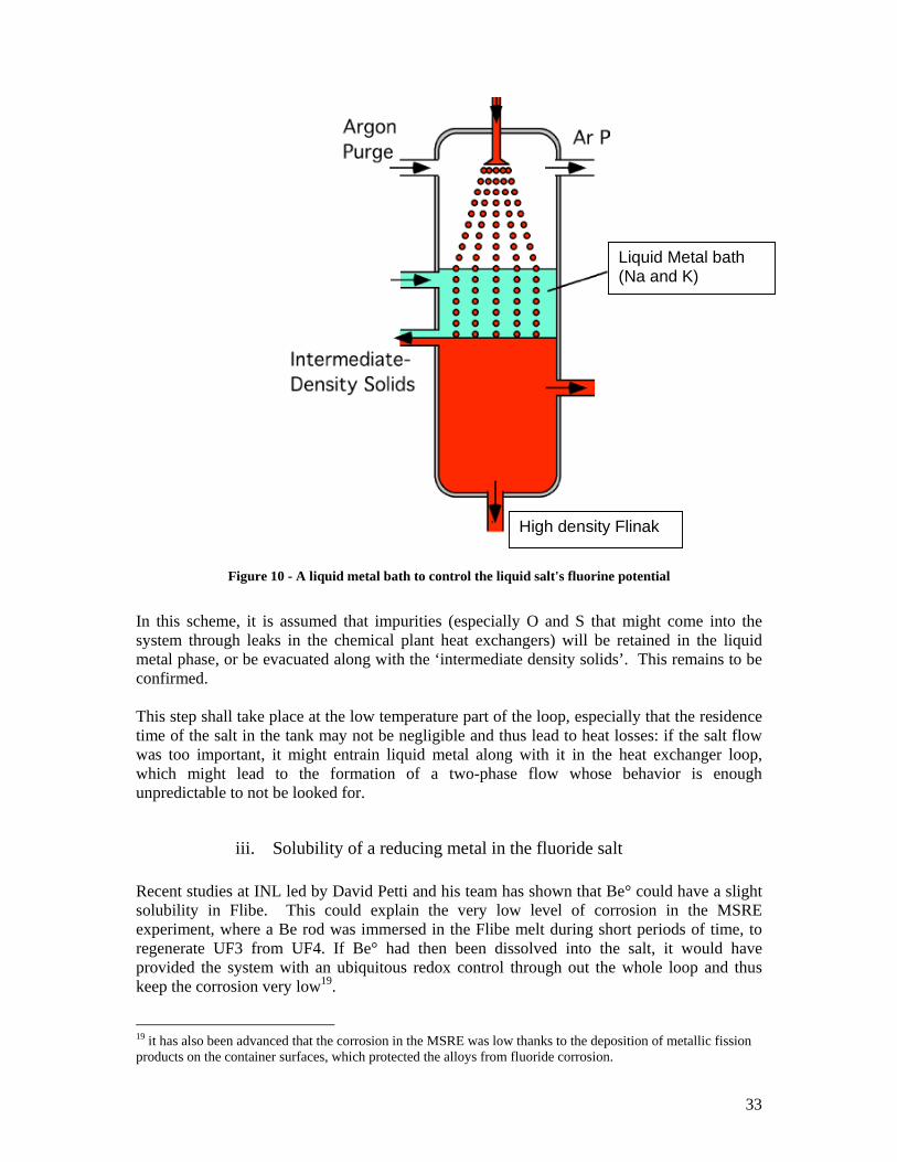
Figure 10 - A liquid metal bath to control the liquid salt's fluorine potential
In this scheme, it is assumed that impurities (especially O and S that might come into the system through leaks in the chemical plant heat exchangers) will be retained in the liquid metal phase, or be evacuated along with the ‘intermediate density solids’. This remains to be confirmed. This step shall take place at the low temperature part of the loop, especially that the residence time of the salt in the tank may not be negligible and thus lead to heat losses: if the salt flow was too important, it might entrain liquid metal along with it in the heat exchanger loop, which might lead to the formation of a two-phase flow whose behavior is enough unpredictable to not be looked for.
iii. Solubility of a reducing metal in the fluoride salt Recent studies at INL led by David Petti and his team has shown that Be° could have a slight solubility in Flibe. This could explain the very low level of corrosion in the MSRE experiment, where a Be rod was immersed in the Flibe melt during short periods of time, to regenerate UF3 from UF4. If Be° had then been dissolved into the salt, it would have provided the system with an ubiquitous redox control through out the whole loop and thus keep the corrosion very low19.
19 it has also been advanced that the corrosion in the MSRE was low thanks to the deposition of metallic fission products on the container surfaces, which protected the alloys from fluoride corrosion.
High density Flinak
Liquid Metal bath (Na and K)
34
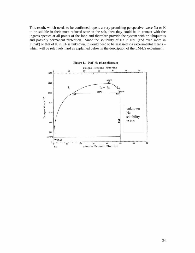
This result, which needs to be confirmed, opens a very promising perspective: were Na or K to be soluble in their most reduced state in the salt, then they could be in contact with the ingress species at all points of the loop and therefore provide the system with an ubiquitous and possibly permanent protection. Since the solubility of Na in NaF (and even more in Flinak) or that of K in KF is unknown, it would need to be assessed via experimental means – which will be relatively hard as explained below in the description of the LM-LS experiment.
Figure 11 - NaF-Na phase diagram
unknown Na solubility in NaF
35
IV. Oxygen, Iodine and Sulfur ingress control The difficulty we are confronted to in the case of the NGNP corrosion study is that one has to consider more than the fluorine potential control to assess the corrosion issues. The chemicals processed in the chemical plant producing hydrogen are very reactive and oxidizing species. Their leaking into the heat exchanging system is plausible, and requires that means be studied to mitigate its impact.
A. Sources of contamination Oxygen can be initially present in the system as an oxide impurity. It is much less likely that S and I will be initially present; however, they could leak into the liquid salt from the hydrogen production plant through the heat exchangers. Sulphur and iodine are reported to be soluble in most molten salts, probably (in the case of iodine) from conversions such as 2I + Cl- -> I2Cl- in LiCl + KCl; on the other hand S2 does not interact with the halide ions [8]. This solubility would enable them to be transported through out the loop, extending the range of their possible impact on the container material. The heat exchangers will very likely not be completely impervious, and some leakage will certainly continuously occur20, possibly causing the infiltration of H2O, H2SO4 or iodine species into the salt. When this ‘background’ leakage rate is exceeded, it will very likely be necessary to shut down the chemical plant to investigate the source of the leak, and prevent a more serious accident from happening. Therefore, means to detect the leaks should be looked for, as well as solutions to mitigate their impact. Given that among the species that would leak to the liquid salt is H2SO4, H2 and maybe HF will be generated by reaction with the container materials and the salt. The H2 detectors used in Na fast KNKII reactors to detect leaks from steam generators (see Appendix 4) could inspire such a gaseous detector.
B. Suggestions to segregate these elements out of the system Sulphur, oxygen and iodine should be segregated out of the salt system – either through methods that would be implemented upon the detection of their presence (which implies finding an adequate detector), or through the provisions developed in the design of the system (which implies developing a control procedure). Segregation in this sense means either being ultimately stripped out of the salt. This led us to think of means to allow this separation that might need to depend on the type of impurities looked at. The easiest case to be dealt with is that in which impurities are volatile elements. They could be extracted from the salt in any place where a free volume exists. If the liquid metal bath approach is validated to keep the fluorine potential low, then the tank where the contact between the salt and the liquid metal takes place would provide such a volume available for 20 a way to diminish its impact could be to use two heat exchangers in series, but this would diminish the efficiency of the whole heat purveying system.
36
the gas expansion out of the salt. To enhance the kinetics of this process, an inert gas such as argon could be injected (counter flow) into the salt melt, or a mixture of salt + inert gas could eventually be sent into centrifuges where the gas would be collected near the rotational axis. In the case of insoluble particles, a filtration would get rid of them. A rigid filter that would be thrown into the system upon detection of a leak, or that would be permanently present and replaced when the head loss across its surface has considerably increased because of its plugging could be set in the cold part of the loop (where the different compounds solubilities are at their lowest). A problem one might ran into concerns the meshing of the filter: the insoluble particles formed upon the ingress of the chemical process plant reactants will not be agglomerated in flakes but rather be present as very small particles, given that a continuous leak through a tiny hole in the huge surface of the heat exchangers proposed is likely to occur (much more than a large rupture leading to a large quantity of reactants being dumped into the salt). A solution might consist in bypassing some of the loop’s flow into a low-Temperature line (not very far away from the salt’s melting point) equipped with a cold trap where the insoluble particles would accumulate. For species that do not fall in either category, that are thus partially soluble in the melt, one should aim at reacting them with other compounds, so as to form a compound which would fall in either of the two previous cases. For example, removal of the sulphides and iodine elements from the MSRE fuel was sought by reaction with the bubbling in of HF/H2 through the following reactions, whose products were gases (which could thus be removed from the melt without extreme difficulty):
2 HF(g) + S2- = 2 F- + H2S (g) whose quotient of reaction21 K > 104 HF(g) + I- = F- + HI (g) whose quotient of reaction K ~600 [5]
It seems that this approach would be the best way to minimize the quantity of oxygen present in the melt upon aggressive ingress. Since we are still looking for a “permanent” and “ubiquitous” if possible method, finding a species that would be soluble into Flinak, and thus be transported through-out the loop, and whose affinity with oxygen be important enough that it would form a stable oxide, whose main attractiveness would be to be insoluble in Flinak – would do the trick. It seems that Na3AlF6 (also known as cryolite) might be our ideal candidate.
Looking for fluoride species, soluble into Flinak and with very stable oxides Given that data about solubilities of oxides and fluorides in Flinak are parsimonious, our method was to aim at species whose oxides are known to be very stable, check whether they have stable fluoride compounds, and investigate whether anything is known about their fluorides and oxides solubilities in molten fluoride salts in general.
Ti Fluorides TiF4 is stable in air, water and ‘do not form oxide species’. Yet, TiF4 is hydroscopic and forms TiF4(2 H2O) complexes, with up to 15% defluorination (in opposition to TiCl4 which is very unstable in the presence of water) [51].
21 without taking into account the activity coefficients
37
Therefore, the Ti fluoride could be used to complex process water from the chemical plant, or even residual water impurities in the melt, thus making it unavailable for corrosion. The equilibrium concentration of TiO2 in the MSRE Flibe based fuel was about 40 weight ppm (at 600°C), meaning that titanium oxide is partially soluble at least in Flibe – although this information may not be of great interest given that this oxide probably did not form from TiF4 but via Ti formed as a fission product (p 140 of [52]). Rare Earths fluorides ‘Unfortunately, the rare earth oxides are not insoluble enough in Flibe to offer a method of separation’ [5]. However, this conclusion of the MSRE22 might not be true for Flinak, given the very different nature of the two salts: Flinak is considered to be made of individual ions, whereas Flibe is currently modelled as including polymers of BeF2. Given that Rare Earths fluorides such as CeF3 have been proposed to monitor the salt’s fluorine potential, and provided that their oxides are insoluble enough in the salt, they might come out as an ideal versatile additive to the salt’s composition. Niobium is an interesting case given that the Nb5+ ion forms a stable oxyon NbO2
+ in molten fluorides [45]. The affinity of O2- to Nb(V) is large in Flinak, resulting in an almost quantitative reaction between O2- and niobium [44]. Could this be used as a means of eliminating the oxides from the melt, provided that an F- getter (or a counter-cation which would not be a structural material’s corrosion product) be available to absorb the F- released by the dissolution of K2NbF7 (likely salt used to introduceNb(V) in the melt) ?
Al fluorides
Al is famous for its affinity to oxygen: as shown in the following figure, Al2O3 is a very stable oxide. It also appears that it is industrially made from its oxide form (alumina) by electrolysis in a fluoride salt melt. These characteristics aroused our interest for aluminium fluorides as O getting species.
22 which wished to get rid of both oxygen and the rare earths, which were generated as fission products and disturbed the fuel salt’s neutronic balance.
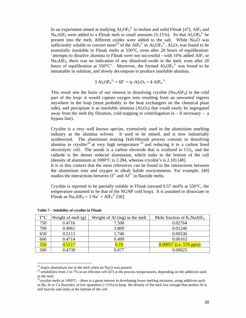
38
In an experiment aimed at studying Al2OF62- in molten and solid Flinak [47], AlF3 and
Na3AlF6 were added to a Flinak melt in small amounts (5-11%). So that Al2OF62- be
present into the melt, different oxides were added to the salt. While Na2O was sufficiently soluble to convert most23 of the AlF6
3- to Al2OF63-, Al2O3 was found to be
essentially insoluble in Flinak melts at 550°C, even after 20 hours of equilibration: ‘attempts to dissolve alumina in Flinak were not successful - with 10% added AlF3 or Na3AlF6, there was no indication of any dissolved oxide in the melt, even after 20 hours of equilibration at 550°C’. Moreover, the formed Al2OF6
3- was found to be metastable in solution, and slowly decompose to produce insoluble alumina.
3 Al2OF62- + 6F- = η–Al2O3 + 4 AlF6
3-
This result sets the basis of our interest in dissolving cryolite (Na3AlF6) in the cold part of the loop: it would capture oxygen ions resulting from an unwanted ingress anywhere in the loop (most probably in the heat exchangers on the chemical plant side), and precipitate it as insoluble alumina (Al2O3) that could easily be segregated away from the melt (by filtration, cold-trapping or centrifugation in – if necessary – a bypass line). Cryolite is a very well known species, extensively used in the aluminium smelting industry as the alumina solvent. It used to be mined, and is now industrially synthesized. The aluminium making Hall-Héroult process consists in dissolving alumina in cryolite24 at very high temperature 25 and reducing it in a carbon lined electrolytic cell. The anode is a carbon electrode that is oxidized to CO2, and the cathode is the denser reduced aluminium, which sinks to the bottom of the cell (density of aluminium at 1000°C is 2.284, whereas cryolite’s is 2.10) [48]. It is in this context that the most references can be found to the interactions between the aluminium ions and oxygen in alkali halide environments. For example, [49] studies the interactions between O2- and Al3+ in fluoride melts. Cryolite is reported to be partially soluble in Flinak (around 0.57 mol% at 550°C, the temperature assumed to be that of the NGNP cold loop). It is assumed to dissociate in Flinak as Na3AlF6 = 3 Na+ + AlF6
3- [50].
Table 7 – Solubility of cryolite in Flinak
T°C Weight of melt (g) Weight of Al (mg) in the melt Mole fraction of K2NaAlF6 750 0.4716 7.508 0.02764 700 0.4961 3.809 0.01246 650 0.5113 1.746 0.00536 600 0.4714 0.499 0.00163 550 0.5117 0.19 0.00057 (i.e. 570 ppm) 500 0.4739 0.077 0.00025
23 major aluminium ion in the melt when no Na2O was present 24 solubilities from 2 to 7% in an efficient cell [47] at the process temperatures, depending on the additives used in the melt 25cryolite melts at 1000°C – there is a great interest in developing lower melting mixtures, using additives such as Ba, Sr or Ca fluorides, in low quantities (<15%) to keep the density of the melt low enough that molten Al is still heavier and sinks at the bottom of the cell.
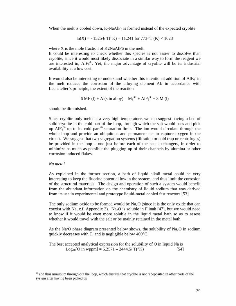
39
When the melt is cooled down, K2NaAlF6 is formed instead of the expected cryolite:
ln(X) = - 15254/ T(°K) + 11.241 for 773<T (K) < 1023 where X is the mole fraction of K2NaAlF6 in the melt. It could be interesting to check whether this species is not easier to dissolve than cryolite, since it would most likely dissociate in a similar way to form the reagent we are interested in, AlF6
3-. Yet, the major advantage of cryolite will be its industrial availability at a low cost. It would also be interesting to understand whether this intentional addition of AlF6
3-in the melt reduces the corrosion of the alloying element Al: in accordance with Lechatelier’s principle, the extent of the reaction
6 MF (l) + Al(s in alloy) = M33+ + AlF6
3- + 3 M (l) should be diminished.
Since cryolite only melts at a very high temperature, we can suggest having a bed of solid cryolite in the cold part of the loop, through which the salt would pass and pick up AlF6
3- up to its cold part26 saturation limit. The ion would circulate through the whole loop and provide an ubiquitous and permanent net to capture oxygen in the circuit. We suggest that two segregation systems (filtration or cold trap or centrifuges) be provided in the loop – one just before each of the heat exchangers, in order to minimize as much as possible the plugging up of their channels by alumina or other corrosion induced flakes.
Na metal As explained in the former section, a bath of liquid alkali metal could be very interesting to keep the fluorine potential low in the system, and thus limit the corrosion of the structural materials. The design and operation of such a system would benefit from the abundant information on the chemistry of liquid sodium that was derived from its use in experimental and prototype liquid-metal cooled fast reactors [53]. The only sodium oxide to be formed would be Na2O (since it is the only oxide that can coexist with Na, c.f. Appendix 3). Na2O is soluble in Flinak [47], but we would need to know if it would be even more soluble in the liquid metal bath so as to assess whether it would travel with the salt or be mainly retained in the metal bath. As the Na/O phase diagram presented below shows, the solubility of Na2O in sodium quickly decreases with T, and is negligible below 400°C. The best accepted analytical expression for the solubility of O in liquid Na is
Log10[O in wppm] = 6.2571 – 2444.5/ T(°K) [54]
26 and thus minimum through-out the loop, which ensures that cryolite is not redeposited in other parts of the system after having been picked up
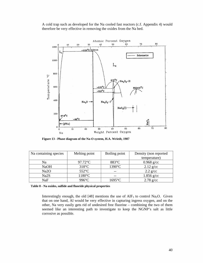
40
A cold trap such as developed for the Na cooled fast reactors (c.f. Appendix 4) would therefore be very effective in removing the oxides from the Na bed.
Figure 13 - Phase diagram of the Na-O system, H.A. Wriedt, 1987
Na containing species Melting point Boiling point Density (non reported
temperature) Na 97.72°C 883°C 0.968 g/cc NaOH 318°C 1390°C 2.12 g/cc Na2O 552°C -- 2.2 g/cc Na2S 1180°C -- 1.856 g/cc NaF 996°C 1695°C 2.78 g/cc
Table 8 - Na oxides, sulfide and fluoride physical properties
Interestingly enough, the old [48] mentions the use of AlF3 to control Na2O. Given that on one hand, Al would be very effective in capturing ingress oxygen, and on the other, Na very easily gets rid of undesired free fluorine – combining the two of them seemed like an interesting path to investigate to keep the NGNP’s salt as little corrosive as possible.
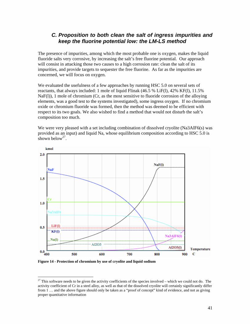
41
C. Proposition to both clean the salt of ingress impurities and keep the fluorine potential low: the LM-LS method
The presence of impurities, among which the most probable one is oxygen, makes the liquid fluoride salts very corrosive, by increasing the salt’s free fluorine potential. Our approach will consist in attacking those two causes to a high corrosion rate: clean the salt of its impurities, and provide targets to sequester the free fluorine. As far as the impurities are concerned, we will focus on oxygen. We evaluated the usefulness of a few approaches by running HSC 5.0 on several sets of reactants, that always included: 1 mole of liquid Flinak (46.5 % LiF(l), 42% KF(l), 11.5% NaF(l)), 1 mole of chromium (Cr, as the most sensitive to fluoride corrosion of the alloying elements, was a good test to the systems investigated), some ingress oxygen. If no chromium oxide or chromium fluoride was formed, then the method was deemed to be efficient with respect to its two goals. We also wished to find a method that would not disturb the salt’s composition too much. We were very pleased with a set including combination of dissolved cryolite (Na3AlF6(s) was provided as an input) and liquid Na, whose equilibrium composition according to HSC 5.0 is shown below27.
Figure 14 - Protection of chromium by use of cryolite and liquid sodium
27 This software needs to be given the activity coefficients of the species involved – which we could not do. The activity coefficient of Cr in a steel alloy, as well as that of the dissolved cryolite will certainly significantly differ from 1 … and the above figure should only be taken as a “proof of concept” kind of evidence, and not as giving proper quantitative information
42
This calculation shows that, at the loop emplacement where sodium, Flinak, chromium, oxygen and cryolite are set in contact:
- cryolite dissolves in Flinak, increasingly with temperature (apparition and increase of Na3AlF6(l) with temperature, for the same amount of initial Na3AlF6(s)),
- the exchange reaction NaF + K = KF + Na does not seem to take place, as if Na was “content” enough with its cryolite based source of fluorine. This however might also be a misconclusion, arisen from a maybe not proper estimate for this reaction’s quotient of reaction (see III.B.2) by the software.
- cryolite reacts with all of the oxygen to form alumina, while its fluorine ions are captured by the liquid metal bath to form NaF in quantities which depend on temperature. Thanks to the reaction
chromium is protected from both O and F corrosion. Moreover, if the liquid metal bath temperature is correctly set, the quantity of NaF may turn out to be that required to form the eutectic Flinak.
Although this calculation needs to be better quantified (especially by taking into account the activity coefficients of the species at hand, and by better incorporating the fact that those species are not well mixed together – for e.g., the chromium atoms are only present on the surface of the container, and not as chromium dust dispersed in the melt), it was exciting enough that we should want to make an experiment out of it. This would be the LM-LS experiment.
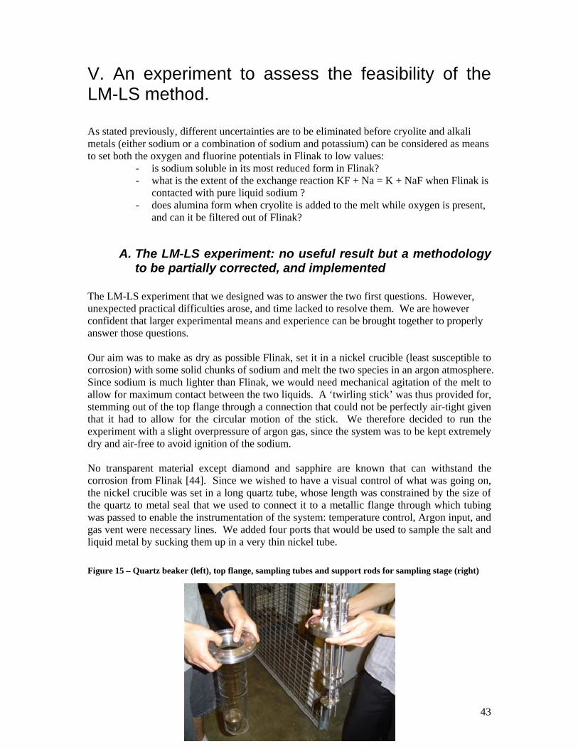
43
V. An experiment to assess the feasibility of the LM-LS method. As stated previously, different uncertainties are to be eliminated before cryolite and alkali metals (either sodium or a combination of sodium and potassium) can be considered as means to set both the oxygen and fluorine potentials in Flinak to low values:
- is sodium soluble in its most reduced form in Flinak? - what is the extent of the exchange reaction KF + Na = K + NaF when Flinak is
contacted with pure liquid sodium ? - does alumina form when cryolite is added to the melt while oxygen is present,
and can it be filtered out of Flinak?
A. The LM-LS experiment: no useful result but a methodology to be partially corrected, and implemented
The LM-LS experiment that we designed was to answer the two first questions. However, unexpected practical difficulties arose, and time lacked to resolve them. We are however confident that larger experimental means and experience can be brought together to properly answer those questions. Our aim was to make as dry as possible Flinak, set it in a nickel crucible (least susceptible to corrosion) with some solid chunks of sodium and melt the two species in an argon atmosphere. Since sodium is much lighter than Flinak, we would need mechanical agitation of the melt to allow for maximum contact between the two liquids. A ‘twirling stick’ was thus provided for, stemming out of the top flange through a connection that could not be perfectly air-tight given that it had to allow for the circular motion of the stick. We therefore decided to run the experiment with a slight overpressure of argon gas, since the system was to be kept extremely dry and air-free to avoid ignition of the sodium. No transparent material except diamond and sapphire are known that can withstand the corrosion from Flinak [44]. Since we wished to have a visual control of what was going on, the nickel crucible was set in a long quartz tube, whose length was constrained by the size of the quartz to metal seal that we used to connect it to a metallic flange through which tubing was passed to enable the instrumentation of the system: temperature control, Argon input, and gas vent were necessary lines. We added four ports that would be used to sample the salt and liquid metal by sucking them up in a very thin nickel tube. Figure 15 – Quartz beaker (left), top flange, sampling tubes and support rods for sampling stage (right)
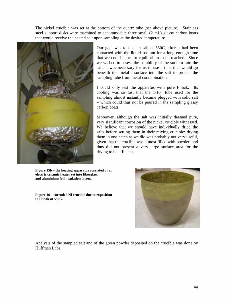
44
The nickel crucible was set at the bottom of the quartz tube (see above picture). Stainless steel support disks were machined to accommodate three small (2 mL) glassy carbon boats that would receive the heated salt upon sampling at the desired temperature.
Our goal was to take in salt at 550C, after it had been contacted with the liquid sodium for a long enough time that we could hope for equilibrium to be reached. Since we wished to assess the solubility of the sodium into the salt, it was necessary for us to use a tube that would go beneath the metal’s surface into the salt to protect the sampling tube from metal contamination. I could only test the apparatus with pure Flinak. Its cooling was so fast that the 1/16” tube used for the sampling almost instantly became plugged with solid salt – which could thus not be poured in the sampling glassy carbon boats. Moreover, although the salt was initially deemed pure, very significant corrosion of the nickel crucible witnessed. We believe that we should have individually dried the salts before setting them in their mixing crucible: drying them in one batch as we did was probably not very useful, given that the crucible was almost filled with powder, and thus did not present a very large surface area for the drying to be efficient.
Figure 15b – the heating apparatus consisted of an electric ceramic heater set into fiberglass and aluminium foil insulation layers.
Figure 16 – corroded Ni crucible due to exposition to Flinak at 550C. Analysis of the sampled salt and of the green powder deposited on the crucible was done by Huffman Labs.
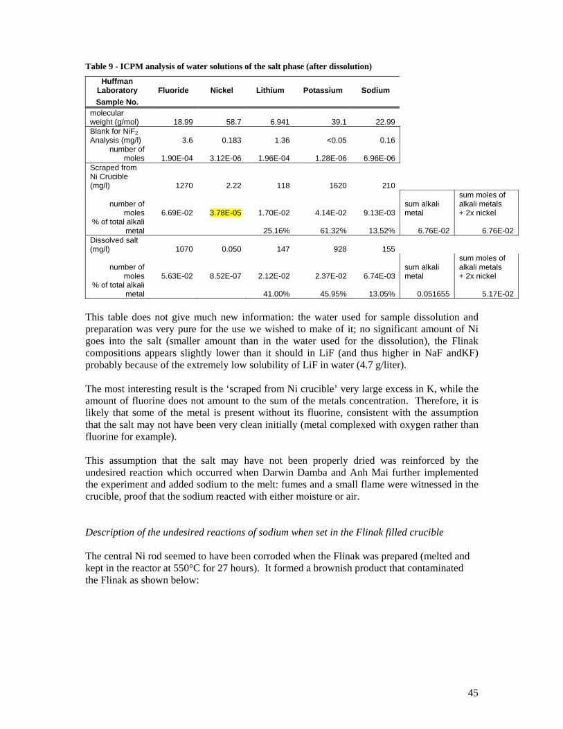
45
Table 9 - ICPM analysis of water solutions of the salt phase (after dissolution)
Huffman Laboratory Fluoride Nickel Lithium Potassium Sodium Sample No.
molecular weight (g/mol) 18.99 58.7 6.941 39.1 22.99 Blank for NiF2 Analysis (mg/l) 3.6 0.183 1.36 <0.05 0.16
number of moles 1.90E-04 3.12E-06 1.96E-04 1.28E-06 6.96E-06
Scraped from Ni Crucible (mg/l) 1270 2.22 118 1620 210
number of moles 6.69E-02 3.78E-05 1.70E-02 4.14E-02 9.13E-03
sum alkali metal
sum moles of alkali metals + 2x nickel
% of total alkali metal
25.16% 61.32% 13.52% 6.76E-02 6.76E-02
Dissolved salt (mg/l) 1070 0.050 147 928 155
number of moles 5.63E-02 8.52E-07 2.12E-02 2.37E-02 6.74E-03
sum alkali metal
sum moles of alkali metals + 2x nickel
% of total alkali metal 41.00% 45.95% 13.05% 0.051655 5.17E-02
This table does not give much new information: the water used for sample dissolution and preparation was very pure for the use we wished to make of it; no significant amount of Ni goes into the salt (smaller amount than in the water used for the dissolution), the Flinak compositions appears slightly lower than it should in LiF (and thus higher in NaF andKF) probably because of the extremely low solubility of LiF in water (4.7 g/liter). The most interesting result is the ‘scraped from Ni crucible’ very large excess in K, while the amount of fluorine does not amount to the sum of the metals concentration. Therefore, it is likely that some of the metal is present without its fluorine, consistent with the assumption that the salt may not have been very clean initially (metal complexed with oxygen rather than fluorine for example). This assumption that the salt may have not been properly dried was reinforced by the undesired reaction which occurred when Darwin Damba and Anh Mai further implemented the experiment and added sodium to the melt: fumes and a small flame were witnessed in the crucible, proof that the sodium reacted with either moisture or air. Description of the undesired reactions of sodium when set in the Flinak filled crucible The central Ni rod seemed to have been corroded when the Flinak was prepared (melted and kept in the reactor at 550°C for 27 hours). It formed a brownish product that contaminated the Flinak as shown below:
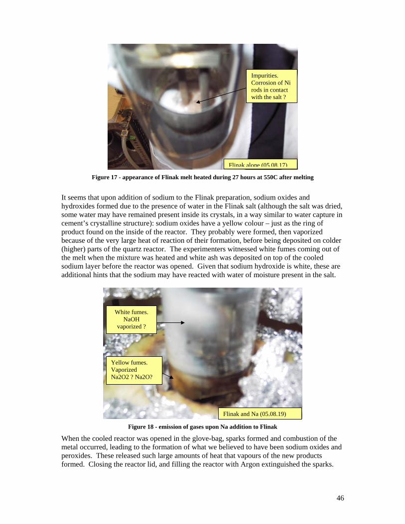
46
Figure 17 - appearance of Flinak melt heated during 27 hours at 550C after melting
It seems that upon addition of sodium to the Flinak preparation, sodium oxides and hydroxides formed due to the presence of water in the Flinak salt (although the salt was dried, some water may have remained present inside its crystals, in a way similar to water capture in cement’s crystalline structure): sodium oxides have a yellow colour – just as the ring of product found on the inside of the reactor. They probably were formed, then vaporized because of the very large heat of reaction of their formation, before being deposited on colder (higher) parts of the quartz reactor. The experimenters witnessed white fumes coming out of the melt when the mixture was heated and white ash was deposited on top of the cooled sodium layer before the reactor was opened. Given that sodium hydroxide is white, these are additional hints that the sodium may have reacted with water of moisture present in the salt.
Figure 18 - emission of gases upon Na addition to Flinak
When the cooled reactor was opened in the glove-bag, sparks formed and combustion of the metal occurred, leading to the formation of what we believed to have been sodium oxides and peroxides. These released such large amounts of heat that vapours of the new products formed. Closing the reactor lid, and filling the reactor with Argon extinguished the sparks.
Impurities. Corrosion of Ni rods in contact with the salt ?
Flinak alone (05.08.17)
Flinak and Na (05.08.19)
White fumes. NaOH
vaporized ?
Yellow fumes. Vaporized Na2O2 ? Na2O?
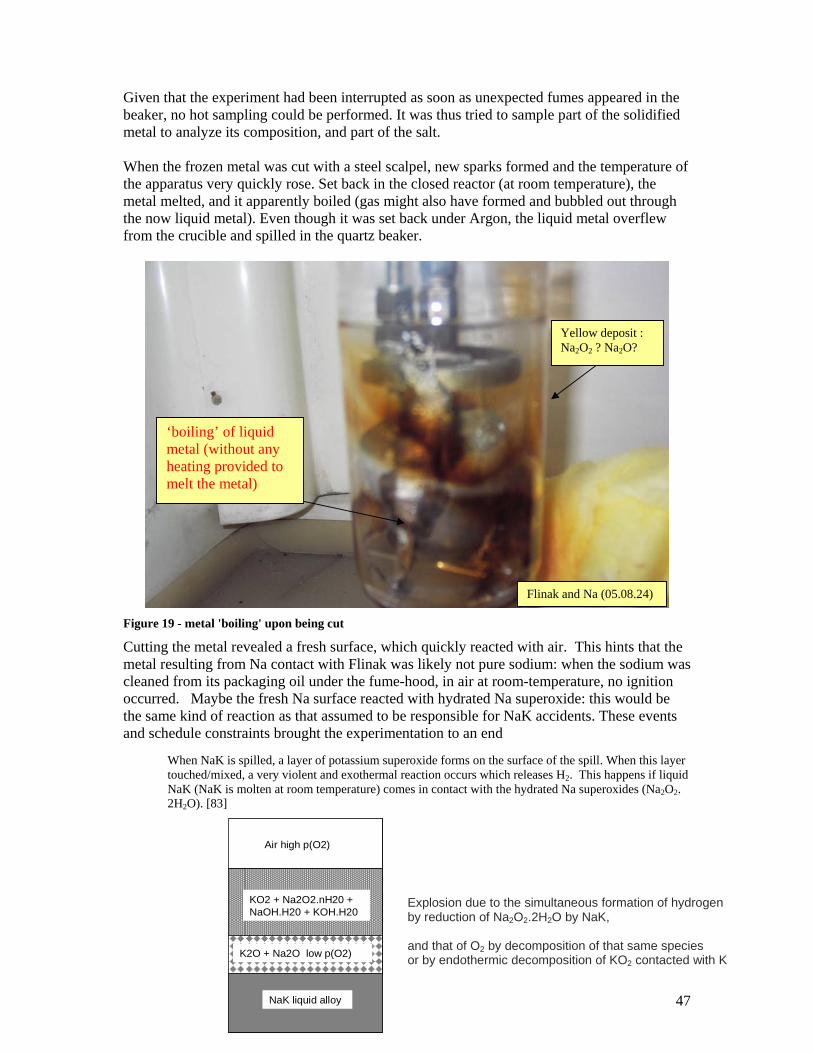
47
Given that the experiment had been interrupted as soon as unexpected fumes appeared in the beaker, no hot sampling could be performed. It was thus tried to sample part of the solidified metal to analyze its composition, and part of the salt. When the frozen metal was cut with a steel scalpel, new sparks formed and the temperature of the apparatus very quickly rose. Set back in the closed reactor (at room temperature), the metal melted, and it apparently boiled (gas might also have formed and bubbled out through the now liquid metal). Even though it was set back under Argon, the liquid metal overflew from the crucible and spilled in the quartz beaker.
Figure 19 - metal 'boiling' upon being cut
Cutting the metal revealed a fresh surface, which quickly reacted with air. This hints that the metal resulting from Na contact with Flinak was likely not pure sodium: when the sodium was cleaned from its packaging oil under the fume-hood, in air at room-temperature, no ignition occurred. Maybe the fresh Na surface reacted with hydrated Na superoxide: this would be the same kind of reaction as that assumed to be responsible for NaK accidents. These events and schedule constraints brought the experimentation to an end
When NaK is spilled, a layer of potassium superoxide forms on the surface of the spill. When this layer touched/mixed, a very violent and exothermal reaction occurs which releases H2. This happens if liquid NaK (NaK is molten at room temperature) comes in contact with the hydrated Na superoxides (Na2O2. 2H2O). [83]
‘boiling’ of liquid metal (without any heating provided to melt the metal)
Yellow deposit : Na2O2 ? Na2O?
Flinak and Na (05.08.24)
Air high p(O2)
KO2 + Na2O2.nH20 + NaOH.H20 + KOH.H20
K2O + Na2O low p(O2)
NaK liquid alloy
Air high p(O2)
KO2 + Na2O2.nH20 + NaOH.H20 + KOH.H20
K2O + Na2O low p(O2)
NaK liquid alloy
Explosion due to the simultaneous formation of hydrogen by reduction of Na2O2.2H2O by NaK, and that of O2 by decomposition of that same species or by endothermic decomposition of KO2 contacted with K
48
B. Suggested methods to analyze the melts Given that we believe that proper care taken in the salt’s preparation, the use of simpler (no mechanical agitation of the liquid salt and metal in a first experimental phase for e.g.) and proper equipment (real sealed gloveboxes of an appropriate size to accommodate the quartz reactor), we wish to provide the reader with suggestions on how to analyze the resulting flinak melt (the metal phase can easily be sampled under an inert atmosphere when cooled down, very carefully reacted with water, and analyzed for Na, K and eventually Ni concentrations for e.g. via ICP).
i. pH measurement This is the analysis which we wished to carry out. It was supposed to consist in dissolving the salt into deionized water, and measuring the change in pH of the resulting solution, between the pure flinak sample, and the one which would have been contacted with liquid metal. Given that Na is a strong reducing agent, the reaction
Na +2 H+ = 2Na+ + H2
would take place, reducing the amount of H+ ions in solution and thus increasing the pH. PH measures being very sensitive (accurate to at least 2 digits), this would have given us good quality quantitative indication on how much Na might have dissolved in the salt. Indeed, if ∆pH= 10-2, then [H+]ini / [H+]fin = exp(0.01) = 1.01005 Therefore, a pH measure would detect a 1% change in [H+] concentration in water. Supposing that the water used is at neutral pH (ie pH=7), one would be able to detect a change of concentration of 10-9 moles/L. Although pure Flinak should not react with water and thus perturb the previously described measurement, there is evidence (Ni crucible corrosion) that it wasn’t be pure in the experimental set-up that we used. A proof dissolution must therefore be ran with non-Na contaminated Flinak, so as to calibrate the above measurement. However, at room temperature, Flinak dissolved with great difficulties into water. We believe that this might be due to the same phenomenon that is responsible for the very low solubility of LiF in water (4.7 g/liter). It might be possible to dissolve the salt by heating up the solution. Moreover, the dissolution times should be carefully monitored: even in pure water, the pH changes with time because of ambient CO2 dissolution in the solution that acidifies the pH:
H2O + CO2 = HCO32- + H+
ii. H2 volume measurement
Gaseous H2 is produced via the reduction of H+ ions by Na. Monitoring the gas volume change of a well-sealed reacting chamber upon dissolution of the salt could also indicate that
49
Na is dissolved in Flinak. This method was used by David Petti and his team with Flibe and Be, which they suggest might be significantly soluble in Flibe. It seemed however difficult to implement in our UCB lab.
iii. Gas analysis
To check whether Na is soluble in Flinak, without trying to obtain quantitative information on the amount of Na dissolved, one could do the dissolution in a hermetically closed cell, and then analyze the cover gas through a gas spectrometer. We however think that this method can not easily be implemented: H2 being an extremely light gas, the gas spectrometer would need to be extremely clean and sensitive to detect its presence.
iv. Electric potential measurements Fluoride melts have much been studied by electrochemists (see bibliography for examples). Monitoring the change in the electric potential during the phase when the melt is contacted with sodium could give interesting insight on the potential change of composition of the melt. The main difficulty of this method would be to ensure sufficient mixing of the sodium and salt phases, and use electrodes that would not contact the liquid sodium layer.
C. What needs to be done beyond the LM-LS Experiment
i. Assess the capacity for HF and heat production This should be done first by using thermodynamical tools, then verified by experiment. HF (a highly neurotoxic gas) should not be generated when Flinak is contacted with water, but might be in the presence of concentrated and hot sulphuric acid. Moreover, calorimetry experiments would be useful to check whether this reaction could release large amounts of heat which would need to be considered a hazard.
ii. Assess the RE solubilities and oxide stabilities Given the interest arisen by the use of bivalent rare earths fluorides to control the salt’s fluorine potential, their solubilities need to be assessed in Flinak. Moreover, the energies of formation of most of these rare earths’ fluorides and oxides are not readily to be found. Darwin Damba compiled a database from various sources so as to have an as complete as possible set of energies of formation. Were some of these species found to have very stable oxides, and were those oxides to be insoluble in Flinak, then the rare earths could become an interesting candidate for both fluorine and oxygen potentials control. Given the interest for fluoride melts of the Partitioning and Transmutation community (programs for fuel pyroprocessing, which need to assess the solubilities of the fission products – among which, rare earths – in the reprocessing solvent), interacting with its members may bring out the looked for properties.
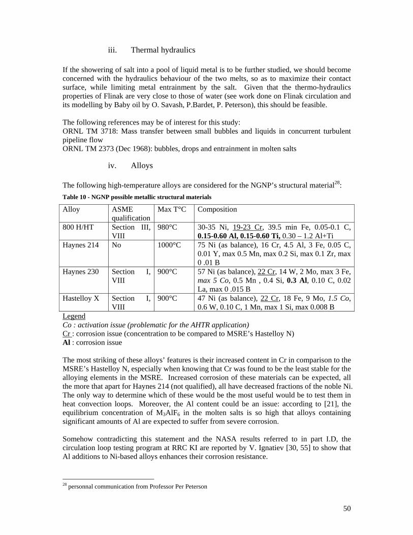
50
iii. Thermal hydraulics If the showering of salt into a pool of liquid metal is to be further studied, we should become concerned with the hydraulics behaviour of the two melts, so as to maximize their contact surface, while limiting metal entrainment by the salt. Given that the thermo-hydraulics properties of Flinak are very close to those of water (see work done on Flinak circulation and its modelling by Baby oil by O. Savash, P.Bardet, P. Peterson), this should be feasible. The following references may be of interest for this study: ORNL TM 3718: Mass transfer between small bubbles and liquids in concurrent turbulent pipeline flow ORNL TM 2373 (Dec 1968): bubbles, drops and entrainment in molten salts
iv. Alloys The following high-temperature alloys are considered for the NGNP’s structural material28: Table 10 - NGNP possible metallic structural materials
Alloy ASME qualification
Max T°C Composition
800 H/HT Section III, VIII
980°C 30-35 Ni, 19-23 Cr, 39.5 min Fe, 0.05-0.1 C, 0.15-0.60 Al, 0.15-0.60 Ti, 0.30 – 1.2 Al+Ti
Haynes 214 No 1000°C 75 Ni (as balance), 16 Cr, 4.5 Al, 3 Fe, 0.05 C, 0.01 Y, max 0.5 Mn, max 0.2 Si, max 0.1 Zr, max 0 .01 B
Haynes 230 Section I, VIII
900°C 57 Ni (as balance), 22 Cr, 14 W, 2 Mo, max 3 Fe, max 5 Co, 0.5 Mn , 0.4 Si, 0.3 Al, 0.10 C, 0.02 La, max 0 .015 B
Hastelloy X Section I, VIII
900°C 47 Ni (as balance), 22 Cr, 18 Fe, 9 Mo, 1.5 Co, 0.6 W, 0.10 C, 1 Mn, max 1 Si, max 0.008 B
Legend Co : activation issue (problematic for the AHTR application) Cr : corrosion issue (concentration to be compared to MSRE’s Hastelloy N) Al : corrosion issue The most striking of these alloys’ features is their increased content in Cr in comparison to the MSRE’s Hastelloy N, especially when knowing that Cr was found to be the least stable for the alloying elements in the MSRE. Increased corrosion of these materials can be expected, all the more that apart for Haynes 214 (not qualified), all have decreased fractions of the noble Ni. The only way to determine which of these would be the most useful would be to test them in heat convection loops. Moreover, the Al content could be an issue: according to [21], the equilibrium concentration of M3AlF6 in the molten salts is so high that alloys containing significant amounts of Al are expected to suffer from severe corrosion. Somehow contradicting this statement and the NASA results referred to in part I.D, the circulation loop testing program at RRC KI are reported by V. Ignatiev [30, 55] to show that Al additions to Ni-based alloys enhances their corrosion resistance.
28 personnal communication from Professor Per Peterson
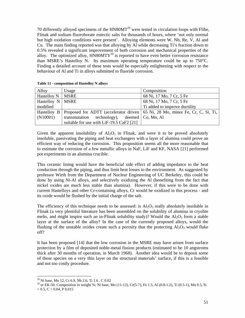
51
70 differently alloyed specimens of the HN80MT29 were tested in circulation loops with Flibe, Flinak and sodium fluoroborate eutectic salts for thousands of hours, where ‘not only normal but high oxidation conditions were present’. Alloying elements were W, Nb, Re, V, Al and Cu. The main finding reported was that alloying by Al while decreasing Ti’s fraction down to 0.5% revealed a significant improvement of both corrosion and mechanical properties of the alloy. The optimized alloy, HN80MTY30 is reported to have even better corrosion resistance than MSRE’s Hastelloy N. Its maximum operating temperature could be up to 750°C. Finding a detailed account of these tests would be especially enlightening with respect to the behaviour of Al and Ti in alloys submitted to fluoride corrosion. Table 11 - composition of Hastelloy N alloys
Alloy Usage Composition Hastelloy N MSRE 68 Ni, 17 Mo, 7 Cr, 5 Fe Hastelloy N modified
MSRE 68 Ni, 17 Mo, 7 Cr, 5 Fe Ti added to improve ductility
Hastelloy B (N10001)
Proposed for ADTT (accelerator driven transmutation technology), deemed suitable for use with LiF-19.5 CaF2 [21]
65 Ni, 28 Mo, minor Fe, Cr, C, Si, Ti, Co, Mn, Al
Given the apparent insolubility of Al2O3 in Flinak, and were it to be proved absolutely insoluble, passivating the piping and heat exchangers with a layer of alumina could prove an efficient way of reducing the corrosion. This proposition seems all the more reasonable that to estimate the corrosion of a few metallic alloys in NaF, LiF and KF, NASA [21] performed pot experiments in an alumina crucible. This ceramic lining would have the beneficial side effect of adding impedance to the heat conduction through the piping, and thus limit heat losses to the environment. As suggested by professor Wirth from the Department of Nuclear Engineering of UC Berkeley, this could be done by using Ni-Al alloys, and selectively oxidizing the Al (benefiting from the fact that nickel oxides are much less stable than alumina). However, if this were to be done with current Hastelloys and other Cr-containing alloys, Cr would be oxidized in this process - and its oxide would be flushed by the initial charge of the salt. The efficiency of this technique needs to be assessed: is Al2O3 really absolutely insoluble in Flinak (a very plentiful literature has been assembled on the solubility of alumina in cryolite melts, and might inspire such an in-Flinak solubility study)? Would the Al2O3 form a stable layer at the surface of the alloy? In the case of the currently proposed alloys, would the flushing of the unstable oxides create such a porosity that the protecting Al2O3 would flake off? It has been proposed [14] that the low corrosion in the MSRE may have arisen from surface protection by a film of deposited noble-metal fission products (estimated to be 10 angstroms thick after 30 months of operation, in March 1968). Another idea would be to deposit some of those species on a very thin layer on the structural materials’ surface, if this is a feasible and not too costly procedure.
29 Ni base, Mo 12, Cr 6.9, Nb 2.6, Ti 1.6 , C 0.02 30 or EK-50. Composition in weight %: Ni base, Mo (11-12), Cr(5-7), Fe 1.5, Al (0.8-1.2), Ti (0.5-1), Mn 0.5, Si < 0.5, C < 0.04, P 0.015
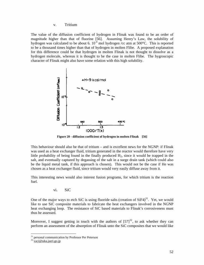
52
v. Tritium
The value of the diffusion coefficient of hydrogen in Flinak was found to be an order of magnitude higher than that of fluorine [56]. Assuming Henry’s Law, the solubility of hydrogen was calculated to be about 6. 10-4 mol hydrogen /cc atm at 500°C. This is reported to be a thousand times higher than that of hydrogen in molten Flibe. A proposed explanation for this difference could be that hydrogen in molten Flinak is not thought to dissolve as a hydrogen molecule, whereas it is thought to be the case in molten Flibe. The hygroscopic character of Flinak might also have some relation with this high solubility.
Figure 20 - diffusion coefficient of hydrogen in molten Flinak [56]
This behaviour should also be that of tritium – and is excellent news for the NGNP: if Flinak was used as a heat exchanger fluid, tritium generated in the reactor would therefore have very little probability of being found in the finally produced H2, since it would be trapped in the salt, and eventually captured by degassing of the salt in a surge drain tank (which could also be the liquid metal tank, if this approach is chosen). This would not be the case if He was chosen as a heat exchanger fluid, since tritium would very easily diffuse away from it. This interesting news would also interest fusion programs, for which tritium is the reaction fuel.
vi. SiC One of the major ways to etch SiC is using fluoride salts (creation of SiF4)31. Yet, we would like to use SiC composite materials to fabricate the heat exchangers involved in the NGNP heat exchanging loop. The resistance of SiC based materials to Flinak’s corrosiveness must thus be assessed. Moreover, I suggest getting in touch with the authors of [57]32, to ask whether they can perform an assessment of the absorption of Flinak unto the SiC composites that we would like
31 personal communication by Professor Per Peterson 32 [email protected]
53
to see used for heat exchangers fabrication. They have performed a series of experiment at 540°C to estimate the Flinak’s absorption on commercially available glassy carbon, pyrolitic graphite, and nickel based Hastelloy B – all found to be more than wished for permeable to the salt. It must however be noted that this issue of salt absorption had already been investigated for graphite in the MSRE, and subsequently mitigated by manufacturing a less porous material.
D. Proposed designs to clean the salt
i. Contamination of the chemical plant by the salt – or the opposite?
The optimal pressure for the hydrogen producing SI cycle is 1 MPa33. Given that the reactor’s pressure will be around 7 MPa, in order to minimize stress on the heat exchanger plates due to pressure unbalance, it is likely that the heat exchanger loop will run at a pressure higher than that of the hydrogen producing process. This would mean that if a heat exchanger was to leak, it would bring H2 producing chemicals into the salt (and not the opposite). Therefore, the risks implied by this event should be compared to that of inducing larger stresses on the heat exchangers, or the efficiency loss induced by running the SI process at a pressure higher than its optimum one, so that the ingress would be from the plant into the loop – which intuitively seems less problematic than the other way round, although this needs to be confirmed.
ii. Initial salt cleaning and charge As appear from the previous discussion, the salts should be as initially clean as feasible. Gas purging shall be implemented, as well as contacting with a bed of liquid Na before charging the salt in the loop. Cleaning of the salt in a fluorinator with salt protected walls may be adequate protection against corrosion (ORNL 4119). The fluorinator walls could be protected by a layer of frozen salt34. A flush salt shall be ran in the loop and discarded before the working salt is charged. A bypass loop could be designed, serving a surge tank whose inert (N2, Ar) cover gas could be analyzed for H2 and tritium. The surge tank would also be used to dump the salt when the chemical plant needs to be isolated from the nuclear island, so that it would not freeze in the piping, but in this tank. The tank would either be provided with continuous heating to keep the salt liquid, or with a punctually operating heater, turned on when the salt would be required to return to the system. Its volume would allow for thermal expansion of the salt upon heating. [74] reports the following volumetric expansion of the salts upon melting : ∆Vm / Vm sol = 10% for Flinak, 29.4% for LiF, 27.4% for NaF, 17.2% for KF upon melting.
iii. Detection systems The leak detection system will need to be pretty sensitive, and respond quickly in time so that if a hole was to be made in the huge surface of the heat exchangers, its consequences can be quickly mitigated. Given the maximum solubility of cryolite in Flinak, a maximum leak rate
33 personal communication by Professor Per Peterson 34 salt studies reported in ORNL 4254 and feasibility demonstrated in ORNL 4344; quantitative studies on the protective layer thickness are reported to have been made in [55]
54
can be easily calculated. The aptitude of the cleaning response to cope with this situation will depend on its sizing (amount of selected ‘cleaning agent’). In the case of large leaks, voids can be detected (ultrasounds, X rays) Part of the salt could also pass through a centrifugal system designed to separate the gas bubbles out of the liquid (such as the centrifuge proposed by I.N. Sviatoslavsky in the context of Flibe cleaning from C, BeO slag, Pb or W in the Hylife-II chamber [58]). A little vortex, as used in the proposed EBWR could be used to the same effect: the heavier liquid would be entrained to the sides of the vortex while the gas would escape through its centre. Experience from liquid metal fast breeder reactors35 and from the MSRE where cover gas36 was analysed in terms of isotopic composition of tracer Xe37 shall be taken advantage of, with the modification that in the NGNP case, the gases to be looked for are H2 and 3H, harder to look for. Continuously assessing the oxide content of the salt will be useful, and ways to do so exist. The form that oxides take in Flinak is Na2O, and Al2O3 when cryolite is added to the salt. To measure the content of these oxides, ORNL researchers [60] reacted the salt with KBrF4 in a Ni cell at 450°C for 2 hours. The oxide (here represented by Al2O3) reacts with KBrF4 according to :
2 Al2O3 + 3 KBrF4 = 4 AlF3 + 3 KBr + 3 O2, with traces of Br2 and BrF
They then measured the resulting oxygen manometrically. The detection limit for this method is reported as being a few 100 ppm of oxides. An improvement to the ORNL method was proposed in 1998 [59], and consisted in switching from a manometric measurement to the use of an yttria-stabilized zirconia (YSZ) oxygen pump, whose detection limit is reported as being as low as 12 µg (ie 0.75 µmoles): after the oxide reaction with KBrF4, the formed O2 is swept through a stabilized zirconia electrochemical cell, and “pumped” out with an applied potential across the zirconia membrane. This simple and inexpensive technique can be used for routine analysis of samples in the 10 to 250 mg range (depending on the oxide assumed content). Cyclic voltammograms and electrochemical measurements have been proposed for the same application [61, 62]. As a side note, let us note that in service inspections will be facilitated (in comparison with the liquid metal cooled systems) by the transparency to visible light of the liquid salt.
iv. Solid cryolite and liquid alkali metal Once these detection systems have been studied, the choice will be easier to make as to which cleaning system can be implemented. The solution that we hope will be investigated is the
35 EBR-I and II, Fermi-I, Superphenix, BN series … 36 in the bowl of the salt pump which was the surge space for the circulating loop, and were dry deoxygenated He at 5 psig blanketed the salt 37 to check for the presence of failed fuel elements
55
joint use of a solid bed of cryolite in the cold part of the loop, and a bath of liquid Na of liquid mixture of Na and K through which the salt would be passed. Filtering of the alumina which we suppose will form when oxygen is present in the melt could be done via a bypass into a cold trap, or into centrifuges. We will need to decide what portion of the salt flowrate we want to be sent to these filtering devices.
E. Safety assessment of the intermediate heat exchanging loop
In addition to the tritium, salt and plant chemicals reactions and ingress detection issues evoked above, potential problems that the NGNP operators might run into regard the management of transients in the heat loop (start up, shut down, consequences of a loss of electric load on H2 production, loss of secondary coolant pressure …), the dimensioning and conception of the interface between the chemical plant and the heat exchanging fluid (what degree of isolation between the process fluids and the liquid salt is needed? is a double walled heat exchanger necessary, as is the case in Na cooled reactors’ steam generators ? would a small tertiary He loop be of any interest, albeit its larger irreversibility and capital cost ?). For example, was flinak to be retained as the heat exchanging fluid, rupture discs shall be designed for relief in case of catastrophic failures of the heat exchangers. Isolation valves should also permit isolation of the loop and Intermediate heat exchanger. Interestingly enough, there was no mechanical valve in the MSRE’s salt piping. Instead, flow was blocked with plugs of salt frozen in flattened sections of the lines. Temperature in the ‘freeze valves’ in the fuel and coolant drain lines were controlled so that they would thaw in 10 to 15 minutes when a drain was requested. A power failure of longer duration also resulted in a drain because the cooling air circulation required to keep the valves frozen was interrupted [14]. This would be an excellent passive safety device to isolate the two plants in case of power shortage.
F. A few words on the Advanced High Temperature Reactor38 ‘The MSRE has shown that salt handling in an operating reactor is quite practical, the salt chemistry is well behaved, there is practically no corrosion, the nuclear characteristics are very close to predictions and the system is dynamically stable. Containment of fission products has been excellent and maintenance of radioactive components has been accomplished without unreasonable delay and with very little radiation exposure’ [14]. This positive judgement on molten fluoride salts behaviour in a nuclear reactor may have fostered the idea of using molten salts, if not as reactor fuel, at least as core coolant. The 2400 MWth LS-VHT Reactor is proposed to work with this scheme, and can be thought of as a NGNP reactor, cooled with molten salt instead of pressurized helium. Gas-cooled reactor type fuel could be used provided that they are shown to be reliable in the 10 to 20
38 now called the LS-VHTR, liquid salt very high temperature reactor
56
W/cc power range which will be that of the AHTR (they are currently rated for 7 W/cc gas cooled reactors39). The same heat exchangers as those developed for the NGNP would be used. Candidate salts for the AHTR include NaF/ZrF4, Flibe (2LiF – BeF2), Flinak (eutectic LiF – NaF – KF), NaF-RbF-ZrF4 [4]. An issue arisen by the use of lithium is this later’s tritium production via 6Li(n,α)3H, where 6Li can be created by 9Be(n,α)6He ->(β decay)6Li in the case of Flibe, and could be initially present in both Flibe and Flinak. Even if 7LiF is used so as to limit the tritium production, this production will be significantly higher than in He cooled reactors (where 3He(n, p)3H takes place), and about equivalent to that of a CANDU reactor. Actinides and FP (esp Cs and I) dissolve in high temperature fluoride salts. Iodine can only be removed from the salt in very oxidizing conditions. The noble fission products coating that took place in the MSRE would most likely also happen in the AHTR, and prevent severe corrosion from being an issue.
39 personal communication from Charles Forsberg (ORNL)
57
Conclusion This report serves multiple purposes, first of which that of economising time to the people that will take up this project in UCB’s Thermal Hydraulics Lab (see the attached CD for a record of the bibliography mentioned articles). We tried in a first part to report current understanding of the mechanisms of corrosion and fluorine chemistry in liquid fluoride salts, and report useful information from the MSRE that would also be of interest to other liquid fluoride salts heat exchanging system. We then become concerned with possible corrosion control methods, whose likely efficiency we analyzed by using a thermodynamical analysis software. Then we described the experiment that was set up to study the one we believe to be the most promising: passing the liquid Flinak through a bed of solid cryolite, before contacting it with a liquid metal bath in the cold part of the loop. The salt would pick up the cryolite up to its solubility limit at the lowest loop temperature (560°C = 833K). We believe that the thus dissolved Al3+ ions will catch ingress O to form insoluble Al2O3 that would be filtered away from the melt. Using a molten bath of Na would 1. keep reducing conditions in loop, 2. maybe catch S as Na2S Although we were not able to run it as we intended to, we believe that it provides a good starting point for further analysis of what could be going on if the proposed system was implemented.

58
Appendices Appendix 1: General properties of molten salts Appendix 2: Production of Hydrogen Appendix 3: Flinak preparation – literature review Appendix 3b: LM-LS experiment procedure Appendix 4: Insights on Na loops operation Appendix 5: Contacts Appendix 6: How to make purchases at UCB – procedure and some vendors which we selected
59
Appendix 1. General Properties of molten (or liquid) salts [8] Molten Salts, as they have long been called, are much better solvents than water. They dissolve water, organic substances, metals, oxides, salts, non-metallic elements … Moreover, a larger variety of solvent temperatures are available: the eutectic AlCl3 + NaCl + KCl melts at 89°C whereas Na3AlF6, also known as cryolite and very well studied because of its use as a solvent for Al2O3 in the aluminium fabrication process, melts at 1003°C. Their extensive use as electrolytes results from their great range of stability in terms of redox potentials: whereas water’s decomposition potential is 1.2 volts, 2.6 volts are required at 700°C to decompose CsCl+MgCl2 eutectic and 3.5 volts for the LiCl + KCl eutectic. Highly electropositive metals can therefore be obtained by electrolysis in these solvents. Non-electrolyte properties: They are similar, although in a very different temperature range, to those of room-temperature liquids: molten alkali halides are clear water-like liquids with comparable to water refractory indexes, viscosity (0.005 to 0.05 P) and surface tension40. Although the surface tensions might be higher than those of room-temperature liquids, they take lower values in molten metals (p 71 of [8]) – the later comparison being of interest in nuclear breeder reactors, where the two fluids have been proposed as core coolants. In molten alkali halides, the forces between the ions are largely coulombic. Molten salts are referred to as acidic or basic with respect to their Lewis properties: acids are electron pair acceptors (BeF2), and bases are electron pair donors (F-) [63]. These salts’ oxidizing properties vary from strong oxidizers to strong reducers, and so do their acidities: Na2S is for example considered basic whereas ZnCl2 will be acidic. (p 154 of [8]) The solubility of refractory materials in molten salts (Al2O3, SiO2, Pt) corresponds to an acid base reaction with a basic oxide dissolving in an acidic melt (or acidic SiO2 dissolving in the basic Na2CO3 for example). When alkali hydroxides are melted in the presence of oxygen and water vapour, peroxides are formed. These solutions will dissolve all known refractories but ThO2 [64]. In the third chapter of [8], molten salts are described as very good solvents for their own metals, which is all the more interesting that Be was long considered insoluble in Flibe (2LiF – BeF2) and that this assumption might be proven wrong [65]. Applications of molten salts include: electrolysis (electropositive metals production, such as Al), molten salt fuel cells, heat transfer, heat storage [21], batteries (LiCl for e.g.), electroplating of refractory metals ([66]; niobium – [67], tantalum – [68], tungsten – [69], hafnium, rhenium – [70]). Chloride salts, inherently more corrosive than fluoride salts, are looked into in the context of fast spectrum transmutation systems, and pyrochemical processing schemes [2]. For the advantages of liquid salts in terms of nuclear applications, see part I.A.
40 the great difference in cohesive force is compensated by the difference in the temperature range of existence
60
Appendix 2. Production of Hydrogen [71] H2 is currently used in the petroleum industry to remove sulfur out of the oils, open benzene rings or break long chains of hydrocarbons. These applications are of particular importance given the declining quality of the available crude oils (use of heavy oils like the Athabasca oil sands). H2 is also massively used in the production of nitrate fertilizers, and in the chemical industry. 95% of the 12 millions tons of H2 consumed in the US in 2002 came from steam reforming of methane, which produced 74 million tons of easy to sequester CO2
41. Steam reforming of methane: CH4 + 2H20 + 185kJ = CO2 + 4H2 This reaction takes place in two steps:
1. the reforming equation: CH4 + H2O -> CO + 3 H2, ∆H= 205.82 kJ
2. the shift reaction: CO + H2O -> CO2 + H2, ∆H= -41.17 kJ
Its efficiency is assessed to be of the order of 70%. A cheap source of hydrogen is water. However, the thermolysis of water H2O=H2+ ½ O2 requires temperatures higher than 2500°C [72]. More than 100 thermochemical water splitting cycles have been found, among which a few promising ones have been selected to lower the temperature for the thermolysis of water. One of those is the sulphur iodine (and hybrid sulphur) cycle. In a first step, water reacts with I2 and SO2 to form hydrogen iodide and sulphuric acid (I2 + SO2 + 2 H2O = 2 HI + H2SO4, takes place at 120°C, ∆H=-52.626 kJ/mol, ∆G=-10.737 kJ/mol). Then, HI and H2SO4 are separated from each other. The I2 and SO2 are recovered and recycled, while hydrogen and oxygen gases are collected: H2SO4 = H2O + SO2 + ½ O2 ( > 850°C, ∆H = 44.348 kJ/mol, ∆G = - 16.412 kJ/mol) 2 HI = H2 + I2 (~ 450°C, ∆H = - 4.210 kJ/mol, ∆G = 10.818 kJ/mol) The efficiency of this cycle could be as high as 50%. The hybrid cycle replaces the lower temperature steps by electrolysis, and does not require I2: SO2 + 2 H2O = H2SO4 + H2 (electrolysis at 80°C). Other cycles are also investigated, such as the Ca-Br process, which has a lower temperature requirement (750°C), but the inconvenience of requiring solid reactants. It is thus a batch process, inherently less effective than the continuous S-I cycle. The solids remain fixed in beds that then must be regenerated with other gases fluxes.
41 Dr Steve Herring, consulting energy at Idaho National Lab, 14th March 2005 NE Colloquium ‘Nuclear Energy and High Temperature Electrolysis for the production of hydrogen’

61
Electrolysis H2O = H2 + ½ O2 Via 2 H3O+ + 2e- -> H2 + 2 H2O at the cathode 3 H2O -> ½ O2 + 2 H3O+ + 2e- at the anode Because electrolysis uses electricity, the overall thermal efficiency of the process should include the efficiency of the electrical power generation. Even though the electrolysis process is about 75% efficient, the overall thermal efficiency generally drops to between 25 and 45%, depending on the electricity producing technology.
62
Appendix 3 - Flinak preparation – literature review
Salt preparation
[74] Analytical reagent grade salts were mixed and melted in a Pt crucible under He, or in a Ni crucible (non tracer salts). Sampling method: capillaries, secured with Ni wire wound around the lower end of the movable Ni rod, were filled with the salt by dipping their mouths into the salt under a vacuum and then feeding He slowly back in the apparatus. 10% volumetric change upon melting. [76] Reagent grade salts. Well mixed and dried in a vacuum oven at 160°C for a week. Powdered mixture melted, and then filtered in an Ar atmosphere to remove black material, using a Ni crucible which had many layers of Pt screen welded over a hole in its bottom. Salt pre-electrolyzed at 1.5V with vitreous carbon anode and SS cathode until the current dropped to about 0.3 mA/cm², so as to eliminate the metal impurities [77] All chemicals are handled in a glove box, under a N2 atmosphere. All electrodes and carbon crucible are dried at about 400 K before using. [47] Preparation of salts by use of a glove box and pre-melting methods under a dry (<5ppm) argon atmosphere or vacuum. Flinak was prepared in a glassy carbon crucible in a closed furnace under Argon, further dried under vacuum at 200°C, mixed, melted and treated at 700°C for 20 hrs before being slowly cooled to RT. [44] All weighing and handling of chemicals were performed in N2 or Ar filled glove boxes with very low water content (dew points ~ - 45°C). Analytical grade initial salts were purified by recrystallisation (operation done twice for Li): a. 100 g of salt in Pt crucible subjected to vacuum treatment at about 400°C for about 8 hours to remove moisture. b. Heated to Tm + 20°C under Ar c. Slowly cooled (4°C/hr i.e. a total of 10hrs) to Tm – 20°C, and then to RT in another 10 hrs. Impurities were by this process concentrated in the central part of the solidified loop (careful crushing of the piece …) [78] Weighing and handling of all chemicals was performed in N2 and Ar filled glove boxes. The box atmosphere was continually passed through an external molecular sieve to remove the water vapor (dew point <-45°C). When not in use, the chemicals were stored in ampoules sealed under vacuum. Mixtures were weighed in glassy carbon crucibles and transferred to a closed furnace for melting and equilibration (700°C for 20 hours) under argon (99.99%). Molten mixtures were solidified in the furnace and transferred to glove boxes for further manipulation. Purification: c.f. [6] The cell (‘reactor’) was assembled within the glove box. [79] Use of glassy carbon crucible [50] LiF = 99.5% Alfa Use of glassy carbon crucible in a quartz cell
63
[80] All manipulations were made in a glove box under an inert atmosphere, filled with purified N2 (<2 ppm H2O). KF, NaF ( 99%) were dried at 300°C overnight under vacuum before being re-crystallized from the molten state in a glassy carbon crucible. Flinak (supplied by L.M. To the from ORNL) was purified by bubbling HF through the molten material at 550°C for 3-4 days, followed by an H2/He sparge to remove additional HF and reduce metal ion impurities. Further purified by electrolysis at an Ni plate cathode with applied potential of –1.5 to –1.8 V. Inconel cell and glassy carbon crucible. [70] Flinak in a graphite crucible, in an airtight SS cell. To dehydrate the salt mixture, 1.5 mol% of KHF2 was added before melting. Salt mixture heated to 300°C under vacuum for 6hrs. Temperature raised up to 600°C at a rate of 100°C/hr under Ar flow. [82] The fluoride eutectic was prepared by mixing pure and finely crushed fluorides (Merck pro analysis), placing them in a Ni crucible and introducing the later in the electrolysis cell, maintained under vacuum during heating by 100°C steps until the salt melts, then under Ar atmosphere. In order to eliminate metallic impurities and oxides, the mixture was pre-electrolysed for 16hr using a 15 cm² nickel cathode and a 5 cm² titanium anode (15 mA/cm²)
Other information
[74] expansion upon melting : ∆Vm / Vm sol = 10% for Flinak, 29.4% for LiF, 27.4% for NaF, 17.2% for KF upon melting Small self-diffusion coefficients Viscosity of Flinak larger than that of other MS: η (LiF) / η (Flinak) = 0.25; η (NaF) / η (Flinak) = 0.19, η (KF)/ η (Flinak) = 0.2 Smaller specific conductance [75] Phase diagram for xAlF3 + (1-x) NaF; thermo calculation on enthalpy of fusion [77] Flinak is an important solvent used in refractory metal electro-deposition and other engineering applications. Is deemed to be a ‘highly corrosive melt’. Mo (from ZnCl2-NaCl [60-40 mole%] or ZnBr2-NaBr), W, are deposited from fused salts; synthesis of high-temperature borides (c.f. Kuznetsov SA, Russian Journal of Electrochemistry 35 (11), 1143-1158 Nov. 1999, Electrochemical Synthesis of high-temperature borides from molten salts); electro-deposition of refractory metal carbides (Journal of the Electrochemical Society, 140 (2): 352-361, Feb 1993, Topor DC, Delman JR); electro-deposition of Niobium-Germanium alloys from molten fluorides (Cohen U, Journal of the Electrochemical Society, 130(7), 1480-1485, 1983) 1 mol% of NiF2 saturates the melt at 973K [47] 10 mol% AlF3 or Na3AlF6 were added to Flinak. Resulted in cloudy melts. [79] Total melting/dissolution of mixtures with 9-11 mol% of alumino-fluoro salts added to Flinak took place near 780°C. [44] No transparent material except diamond can withstand Flinak corrosion.
64
Affinity of oxides to Nb is large: almost quantitative reaction between Nb (2.7 mol% were used) or K2NbF7 and oxides. [78] Ni is moderately attacked by Flinak at 700°C: weight loss of Ni plate with a surface area of 6.5 cm² is 0.7 mg/cm² over 24 hrs. Use of gold and diamond (ZnSe and Si were attacked by Flinak. C.f. exp). [70] Processes using molten salt are employed at industrial level for refractory metals such as W and Hf. [81] Thermo-chemistry of ionic liquid heat transfer fluids. Water content of the ionic liquids was performed by Karl Fischer titration. Measures of thermal conductivity, density, viscosity and heat capacity of three low melting temperature molten salts. [38] Electrochemical study of anodic dissolution of Fe and Ni at 600°C in Flinak. Flinak has a very negative cathodic limit, corresponding to the K+ ions reduction (c.f. ref 16 – saved as “Application de la volt-ampérométrie convolutionnelle à la détermination du coefficient de diffusion des ions TiF6 3– dans l'eutectique LiF–NaF–KF de 600°C a 900°C”). The anodic limit corresponds to the oxidation of F-. The Ni crucible is used as the comparison electrode, a glassy carbon sheet as the counter-electrode. KF = K + ½ F2: E = 4.96 V at 600°C (calculated from thermodynamic data from JANAF 1971). E0 Fe/Fe² + = 1.75 +/- 0.01V / K+; E0 Ni/Ni
2+ = 2.16 +/- 0.01V / K+
(smaller than what theory would have it, probably because of complexation leading to FeF6 4- and NiF6 4-, identified by Raman spectroscopy) [82] 1.5 mol% Ti3+ in melt (for plating)
Documents to be found which may yield additional information
[74] LiF+BeF2 and Flinak systems may have technological applications as fuel or coolant solvents in nuclear reactors and in solar energy storage: Ref 1: Report of the Research Committee of MR technology, MSBR, Atomic Energy Society of Japan, 1979 Ref 2: A. BORUCKA, Survey and Selection of inorganic Salts for application to thermal energy storage, US energy research and development administration, 10F2 ERDA59 (or ERDA S9?), 1975 [77] Refs 1 to 3: behavior of electro-active constituents was investigated (refractory metallic ions, oxides …) History of Electro-analytical chemistry in Molten Salts, ACS (American Chemical Society, Washington DC) symposium series [0097-6156] Laitinen HA, 1989 vol 390 pg 417 Electro-coating from Molten Salts, Journal of applied electrochemistry, 9(4) 411-426, 1979 [47] Check E.W. Dewing for all kind of studies on cryolite. At UC Berkeley can be found : Engi TN1.M5721 Activities in the system cryolite-alumina, Metallurgical and materials transactions-A, Physical Metallurgy and Materials Science [1073-5622], 1997, vol 28 iss 6, pg 1089; Engi TN1.M5722
65
Thermodynamics of the system NaF-AlF3: Part VII. Non-stoichiometric solid cryolite METALLURGICAL AND MATERIALS TRANSACTIONS B-PROCESS METALLURGY AND MATERIALS PROCESSING SCIENCE 28 (6): 1095-1097 DEC 1997: gives activity of NaF and reaction constants, Solutions of CeO2 in cryolite melts, METALLURGICAL AND MATERIALS TRANSACTIONS B-PROCESS METALLURGY AND MATERIALS PROCESSING SCIENCE 28 (6): 1257-1257 DEC 1997 DGCeF3 and its activity coefficient in cryolite: METALLURGICAL AND MATERIALS TRANSACTIONS B-PROCESS METALLURGY AND MATERIALS PROCESSING SCIENCE 21 (5): 861-865 oct 1990 Activities in the system LiF-NaF-AlF3: METALLURGICAL AND MATERIALS TRANSACTIONS B-PROCESS METALLURGY AND MATERIALS PROCESSING SCIENCE 18 (2): 409-414 June 1987 Engi TN1. M5722 Activities in Li3AF6-Na3AlF6 melts, Journal of metals, vol 36:12 pg 94, 1984 Activities in NaF-AlF3 melts saturated with Al2O3, Yoshida K, Dewing EW, Metallurgical Transactions 3(3), pg 683, 1972) Engi TP 795.A62 Phase diagram of a portion of system Na3AlF6-AlF3-Al2O3, Journal of American Ceramic Society, 1975 vol 58 iss7-8 pg 288 [38] ref 9 = [82]: description of dehydratation and purification of the mixture
Ideas
Contact the von Barner et al. team in Denmark for all Flinak investigations
66
Appendix 3b: LM-LS Experiment Procedure – August 2005
Preliminary notes
Description of the set-up
The reactor consists of a quartz beaker, equipped with a quart-to-metal seal that connects it to a stainless steel flange.
Tubing and rods are passed through the flange into the beaker:
• two sampling 1/8” Ni tubes,
• a central ¼” Ni tube used for agitation purposes, which holds the below described ‘sampling floor’ and through which a thermo-couple is inserted,
• a vacuum port,
• an Ar entry port,
• a vent port,
• and two stainless steel rods, supporting the below described ‘buffer plates’.
The vent port is connected to plastic tubing dipping into a vacuum-pump oil filled beaker. The Ar entry port is connected to a bottle of 99.999% pure Ar. The vacuum port is connected to a throttled gas pump.
From top to bottom, the reactor consists of:
• the stainless steel lid
• two ‘buffer plates’: 1/3” thick stainless steel (316 and 304) plates, whose purpose is to limit flow convection inside the reactor
• the ‘sampling floor’: 1/3” thick stainless steel (304) plate, carved so as to accommodate three glassy carbon 2 mL sampling crucibles, supporting a ¼” Ni piece of tubing used as a sheath through which the molten salt (MS) sampling tube will reach the salt without touching the metal phase.
• A 100 mL, 60 mm high Ni crucible where the chemicals will be mixed.
The reactor is hold in place by a metallic support ring connected to a cast iron stand by a stainless steel rod.
To heat the reactor, a ceramic and fiber glass heater (rated to 900W) is used. It is set on a jack that can be lowered if needed in an emergency to remove as fast as possible heat generation from the reactor’s environment. The jack’s vertical movement should have an amplitude of at least 5”.
Two inflatable glove bags (G) will be used:
• G1 outside the fume-hood will be used to prepare the fluoride salts and load them inside the reactor,
• G2 inside the fume-hood will be used for manipulating the alkali metals.
67
G1 should contain a three-beam mass balance, three Teflon coated spatulas, at least three ampoules to be sealed, the NaF, KF and LiF containers, a support to keep the reactor upright (cork or polyester ring for example).
G2 should contain the above sealed ampoules once filled, the metal (M) containers, very dry sand, a Hexane filled bottle, as well as the anhydrous ethanol bottle. It should also contain 4 beakers (3 hexane beakers and one for ethanol, which will be used to clean M), a precise analytical balance, parafilm and a glass watch (to cover the above beakers when not in use).
Both mass balances should be tared with the initially empty Ni crucible.
The Ar flow is divided into two main streams S1 (connected to G1) and S2 (that goes in the fume-hood). S2 is divided in another two streams: S2a connected to the reactor and S2b connected to G2.
S2a will also be used in step D, to create an inert gas buffer over the metal to be dissolved in water.
General Safety
Each experimenter shall read the MSDS kept in a conspicuous binder in 1107 and relative to the different chemicals used in this experiment. Every one of them should also be sure to know how to handle the class-D fire extinguisher.
Experimenters shall wear eye-protection, gloves and a lab coat.
One shall not eat or drink in the neighbourhood of the set-up.
One shall hand-wash after performing manipulations.
A tray shall be set in each of the glove-bags to contain an eventual spill of material.
In the event of a metal fire, dry sand is to be poured on the ignited sample. If this proved insufficient to control the hazard, make use of the fire extinguisher (be however aware that this will ruin this run of experiment).
The MF (where M = Na, K or Li) containing bottles are always to be kept (closed) in G1.
MF are toxic chemicals, and should not be contacted with water, moisture or oxidizing agents. Do not inhale, ingest or contact with skin or eyes.
The M (where M=Na or K) containers are always to be kept (closed) in G2. M are extremely reactive and should not be contacted with water, moisture, air or oxidizing agents. Do not inhale, ingest or contact with skin or eyes.
No water, moisture traces or air whatsoever should ever be allowed in the reactor or either G1 or G2. All cleaning performed in the glove boxes will be done using dry micro-wipes.
68
Notes on Procedure
Agitation will only be provided once the species studied are in a molten state. It shall always be done under Ar slight overpressure, to prevent air from penetrating inside the system through the slight openings in the U-torr, necessary to ensure motion of the central Ni rod.
This will be done by rotating the central Ni rod (into which the thermo-couple will be inserted) with a drill whose speed will be adjusted by using a potentiometer.
For temperature measurements are to be made, the agitation will be stopped.
When unloading the reactor, all potential air entry ports shall be closed using rubber caps.
When not in use for sampling, the two sampling rods are to be kept in position ‘up’.
During cooling of the reactor after sampling, the sampling floor shall be lifted (so that the rods do not get stuck in the melt that is freezing). However, when cooling after Flinak preparation, this should not be the case: leave the sampling stage in place, even though this results in having the rods stuck in the salt. Indeed, there should be as little opportunity as possible for metal to come into the Ni sheath designed to have clean sampling of the salt phase. Eventually, carve a hole in the frozen Flinak into which the metal will be placed before the Flinak melts (at a much higher temperature than M: 455°C v.s. less than 100°C).
For the first flinak-only run (= reference sample, no metal present), proceed in exactly the same way as if metal was to be inserted in the melt (unload the reactor, open it with Hex and ethanol present …).
Labelling of the different bottles or beakers used should make mention of:
- date sealed
- species introduced
- quantities introduced (or estimate)
- round number
- if different from air, atmosphere under which is sealed.
Other
A notebook shall be kept near the set-up to record whatever actions are performed, and at what time.
RT= room temperature
69
Procedure 1 – placing/ removing parts from the glove-bag
The reactor vessel will need to be moved in and out of the glove-bag. To do so, follow the following procedure.
If the glove-bag has never been inflated:
a. Remove the glove-bag from the envelope and unfold
b. Inflate the glove-bag: insert the small plastic adapter into the tabulation and attach rubber tubing from the gas line. Connect the tubing to the Ar source, and purge the residual air from the glove-bag.
c. While purging, insert all equipment and chemicals in the glove-bag.
d. Close equipment sleeve with the supplied handy lock closure. When closing, be sure to leave enough space for the electrical wires. They shall be connected to the glove-bag body using tape.
e. Lower the Ar flow – may need even to stop it. Do not over-inflate (fil like a soft pillow, not like a balloon).
If the glove-bag has already been inflated, and contains material:
a. Turn the Ar flow back on.
b. Open the handy lock closure, and somehow deflate the glove-bag.
c. While purging, insert all equipment and chemicals in the glove-bag
d. Purge the glove-bag: further deflate it, keep the Ar flow moving.
e. Close equipment sleeve with the supplied handy lock closure. When closing, be sure to leave enough space for the electrical wires. They shall be connected to the glove-bag body using tape.
f. Lower the Ar flow – may need even to stop it. Do not over-inflate (fill like a soft pillow, not like a balloon).
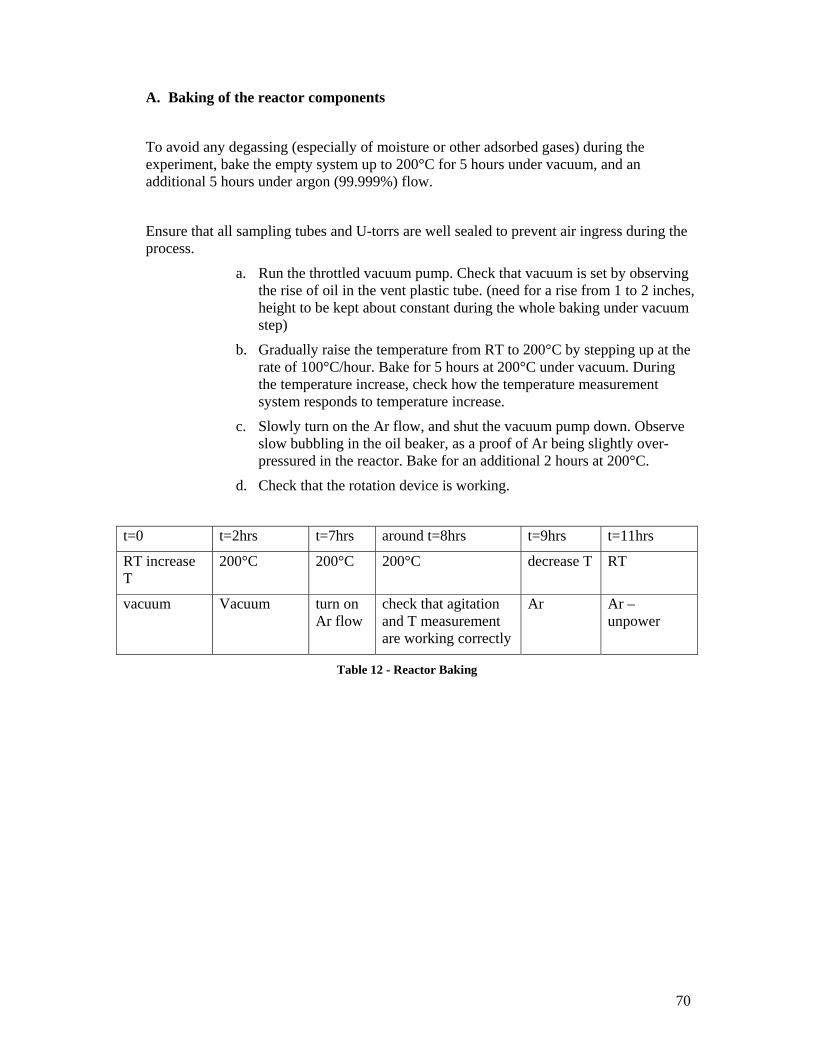
70
A. Baking of the reactor components
To avoid any degassing (especially of moisture or other adsorbed gases) during the experiment, bake the empty system up to 200°C for 5 hours under vacuum, and an additional 5 hours under argon (99.999%) flow.
Ensure that all sampling tubes and U-torrs are well sealed to prevent air ingress during the process.
a. Run the throttled vacuum pump. Check that vacuum is set by observing the rise of oil in the vent plastic tube. (need for a rise from 1 to 2 inches, height to be kept about constant during the whole baking under vacuum step)
b. Gradually raise the temperature from RT to 200°C by stepping up at the rate of 100°C/hour. Bake for 5 hours at 200°C under vacuum. During the temperature increase, check how the temperature measurement system responds to temperature increase.
c. Slowly turn on the Ar flow, and shut the vacuum pump down. Observe slow bubbling in the oil beaker, as a proof of Ar being slightly over-pressured in the reactor. Bake for an additional 2 hours at 200°C.
d. Check that the rotation device is working.
t=0 t=2hrs t=7hrs around t=8hrs t=9hrs t=11hrs
RT increase T
200°C 200°C 200°C decrease T RT
vacuum Vacuum turn on Ar flow
check that agitation and T measurement are working correctly
Ar Ar – unpower
Table 12 - Reactor Baking
71
B. Flinak preparation
Safety
Alkali fluoride salts are toxic chemicals. The corresponding MSDS should be read prior to manipulation.
They should be kept out of contact from water, moisture and oxidizing agents. Contacting them with moisture may result in the generation of the neurotoxic gas HF.
They therefore should be handled under an inert atmosphere or vacuum, in G1or the reactor vessel. They should always be stored in tightly sealed containers in the sealed G1.
0. Baking of the reactor components
1. Drying of the initial salts
The reactor is to always be kept straight, to avoid toppling of the different movable parts (especially Ni crucible and glassy carbon containers).
a. Clean (using dry micro-wipes) the Teflon coated spatulas used for sampling the salts.
b. Disconnect all gas, vacuum and vent lines from the reactor; disconnect rotation and temperature measurement devices.
c. Close all potential air entry ports by using the black rubber stoppers.
d. Set the reactor in the deflated G1.
e. Use of procedure 1 to inflate the glove-bag.
f. Open the reactor, take the Ni crucible out and tar it.
g. Open the NaF container fill the calibrated Ni crucible with NaF using one of the Teflon coated spatulas. Close the NaF container.
h. Measure the mass of NaF set in the crucible.
i. Set the filled crucible in the reactor.
j. Close the reactor, and all its air entry ports.
k. Take the reactor out of G1 (if needed, deflate G1 to do so), set it in the support ring and in the heater. The bottom 4 ½” of the container are to be in the 6” high heater.
l. Connect the gas, vacuum and vent lines. Check that the rotating device is plugged in.
m. Run the vacuum pump. Be careful to slowly set the vacuum to its final value, which should be low: rise of 2 to 3 inches of the oil in the vent plastic tube dipped in the oil filled beaker. (use low pump aspiration is required so that the NaF powder will not be flying around in the reactor).
n. Slowly (100°C/hour) raise the temperature to 400°C.
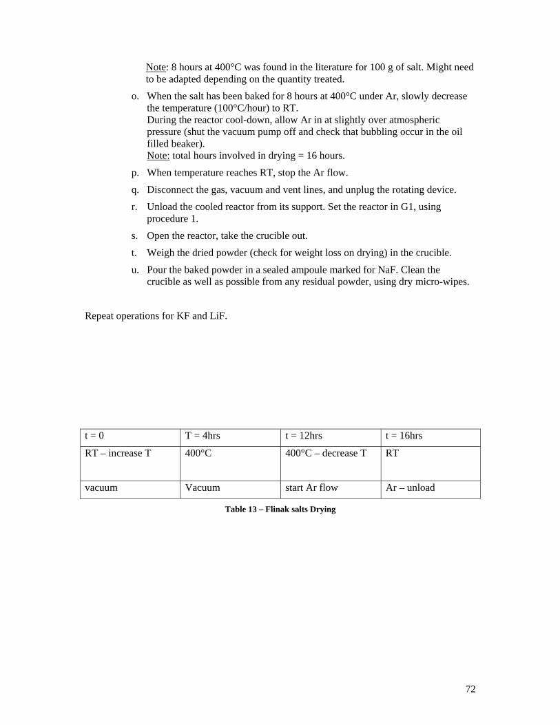
72
Note: 8 hours at 400°C was found in the literature for 100 g of salt. Might need to be adapted depending on the quantity treated.
o. When the salt has been baked for 8 hours at 400°C under Ar, slowly decrease the temperature (100°C/hour) to RT. During the reactor cool-down, allow Ar in at slightly over atmospheric pressure (shut the vacuum pump off and check that bubbling occur in the oil filled beaker). Note: total hours involved in drying = 16 hours.
p. When temperature reaches RT, stop the Ar flow.
q. Disconnect the gas, vacuum and vent lines, and unplug the rotating device.
r. Unload the cooled reactor from its support. Set the reactor in G1, using procedure 1.
s. Open the reactor, take the crucible out.
t. Weigh the dried powder (check for weight loss on drying) in the crucible.
u. Pour the baked powder in a sealed ampoule marked for NaF. Clean the crucible as well as possible from any residual powder, using dry micro-wipes.
Repeat operations for KF and LiF.
t = 0 T = 4hrs t = 12hrs t = 16hrs
RT – increase T 400°C 400°C – decrease T RT
vacuum Vacuum start Ar flow Ar – unload
Table 13 – Flinak salts Drying
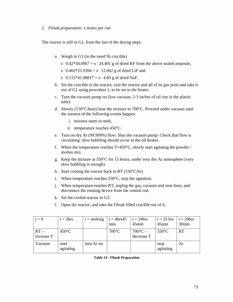
73
2. Flinak preparation: x moles per run
The reactor is still in G1, from the last of the drying steps.
a. Weigh in G1 (in the tared Ni crucible)
x . 0.42*58.0967 = x . 24.401 g of dried KF from the above sealed ampoule,
x . 0.465*25.9394 = x . 12.062 g of dried LiF and
x . 0.115*41.98817 = x . 4.83 g of dried NaF.
b. Set the crucible in the reactor, seal the reactor and all of its gas ports and take it out of G1 using procedure 1, to be set in the heater.
c. Turn the vacuum pump on (low vacuum, 2-3 inches of oil rise in the plastic tube).
d. Slowly (150°C/hour) heat the mixture to 700°C. Proceed under vacuum until the soonest of the following events happen:
i. mixture starts to melt,
ii. temperature reaches 450°C.
e. Turn on dry Ar (99.999%) flow. Shut the vacuum pump. Check that flow is circulating: slow bubbling should occur in the oil beaker.
f. When the temperature reaches T=450°C, slowly start agitating the powder / molten mix.
g. Keep the mixture at 550°C for 15 hours, under very dry Ar atmosphere (very slow bubbling is enough).
h. Start cooling the reactor back to RT (150°C/hr).
i. When temperature reaches 550°C, stop the agitation.
j. When temperature reaches RT, unplug the gas, vacuum and vent lines, and disconnect the rotating device from the central rod.
k. Set the cooled reactor in G2.
l. Open the reactor, and take the Flinak filled crucible out of it.
t = 0 t = 3hrs t = melting t = 4hrs45 min
t = 24hrs 45min
t = 25 hrs 45min
t = 29hrs 30min
RT – increase T
450°C 700°C 700°C – decrease T
550°C RT
Vacuum start agitating
turn Ar on stop agitating
Ar
Table 14 - Flinak Preparation
74
C. Alkali metal M preparation: y moles
Safety
Alkali metals are dangerous chemicals. The corresponding MSDS should be read prior to manipulation.
They should be kept out of contact from water, moisture and oxidizing agents. Contacting them with moisture will result in the generation of the explosively hazardous H2.
They therefore should be handled under an inert atmosphere or vacuum, in G2 or the reactor vessel. They should always be stored in tightly sealed containers, filled with mineral oil to avoid oxide formation, in the sealed G2.
Be assured that G2 is inflated with very dry Ar.
Unplug all electrical devices (but the analytical balance) and heat sources (flammable ethanol and hexane vapours will be present in G2) when working with these metals.
The dipping of the metals in ethanol is designed to remove the likely oxide layer on the surface of the metals. The reactions involved is exothermic, and releases the hazardous gas H2 (for memory, 4% H2 in air consists in an explosive hazard). The foam appearing on the metal is actually H2.
Should a fire start in the glove box, quickly pour sand on the metal which started it. Be sure to get familiar with the manipulation of the yellow class-D (metal fires) extinguisher set against the cage, to be used if the fire hazard can not be controlled using sand.
Do NOT use the red extinguishers (class A, B or C fires).
Procedure
a. Open the M container. With the Teflon coated forceps, take a chip out of the oil. Close the container.
b. Dip the chip in beaker Hex 1 to remove the storage mineral oil from it.
c. Dip in Hex 2 to further dissolve the oil.
d. QUICKLY (esp. for K) dip in ethanol (foam should form on the surface of the metal – due to H2 emission), and from there into Hex 3.
e. Check that the metal surface is shiny. If not, dip again in ethanol and in Hex 3.
f. Weigh the clean and dry chip. Put it into the Flinak filled Ni crucible.
g. Clean as many chips as necessary to obtain the required amount of M in the mixture: y . 39.0983 grams of K, or y . 22.98977 grams of Na.
h. Cover the Hex and ethanol beakers with parafilm or glass watches to avoid evaporation (flammable gases). Be aware that hexane might dissolve the parafilm.
75
i. Set the filled crucible in the reactor.
j. Close the reactor, take it out of G2 and put it in the heater.
k. Connect the gas, vacuum and vent lines; check that the rotating device is in place.
l. Pour the used Hex and ethanol into waste bottles properly labelled, to ultimately be discarded through EHS. Set the corresponding dry beakers back in G2.
D. Equilibration of the two phases
a. Heat up the mixture:
i. up to 100°C for 1 hr, then
ii. stay ½ hr at 100°C, then
iii. 100°C per hour up to 550°C
This should be done under vacuum till the mixture melts.
b. When the mixture starts melting, turn on the Ar flow.
c. When the mixture starts melting and when the Ar flow is set (bubbles in the oil containing beaker), continuously agitate the melt. Stop agitating at t = 24 hrs. the use of t = 20 hrs for equilibrating the phases stems from
d. When the phases are well separated, sample the phases (one metallic sample and two salt samples).
e. Cool down the system (150°C/hr), until it reaches RT and everything in it is frozen. Note: depending of the Na to K ratio in the metal phase, the metal phase might remain be liquid at RT. If remains liquid after 1 hr at RT, proceed with step d.
f. Unplug the gas, vacuum and vent lines, and disconnect the rotating device from the central rod. Close all air entry ports by using the black rubber stoppers.
g. Unplug all heat generating and electrical devices.
h. Unload the reactor from its support.
i. Set the reactor in G2, following procedure 1.
j. Open the reactor. Take the sampling crucibles out, and if the sample is solid, set in plastic vials until further analysis is pursued.
k. Leave the vials in G2. If the sample is liquid, cover the sampling crucible with parafilm.
l. Empty the Ni crucible. Keep what is left of the salt and liquid metal phases in two other properly labelled and tightly sealed under Ar plastic bottles, to be kept in a transparent plastic bag under the fume-hood.
m. Clean the Ni crucible as well as possible using a micro-swipe.
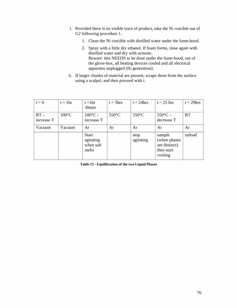
76
i. Provided there is no visible trace of product, take the Ni crucible out of G2 following procedure 1.
1. Clean the Ni crucible with distilled water under the fume-hood.
2. Spray with a little dry ethanol. If foam forms, rinse again with distilled water and dry with acetone. Beware: this NEEDS to be done under the fume-hood, out of the glove-box, all heating devices cooled and all electrical apparatus unplugged (H2 generation).
ii. If larger chunks of material are present, scrape them from the surface using a scalpel, and then proceed with i.
t = 0 t = 1hr t =1hr 30min
t = 5hrs t = 24hrs t ~ 25 hrs t = 29hrs
RT – increase T
100°C 100°C - increase T
550°C 550°C 550°C – decrease T
RT
Vacuum Vacuum Ar Ar Ar Ar Ar
Start agitating when salt melts
stop agitating
sample (when phases are distinct) then start cooling
unload
Table 15 - Equilibration of the two Liquid Phases
77
E. Phase composition analysis
Safety
Dissolution of the fluoride salts may generate neurotoxic HF. Be assured to do all manipulations under the properly closed fume-hood, and at a slow rate to not accumulate HF.
Dissolution of the alkali metals is a very hazardous step, generating explosive H2. Proceed under Ar cover and very slowly (to avoid accumulation of the gas).
Always have sand handy in case of ignition of the metal.
Unplug all heat generating and other electrical devices (but the analytical mass balance).
Procedure
If space under the fume-hood is not sufficient, the empty reactor system (stand + reactor + jack) is to be moved out of the furnace, for more ease in the following manipulations.
The burette stand is to be set under the fume-hood, and the burette filled with distilled water.
A pH-measuring apparatus will be attached to the stand when the dissolution is completed.
The samples shall be dissolved in 300 mL beakers.
The Ar flow S2a is to be set over the beaker, to make an ‘Ar cloud’ over the sample to be dissolved.
a. if Huffman labs: we are to provide them with already dissolved samples.
i. Take the samples filled vials out of G2 into G3.
ii. Set the Ar S2a flow from the reactor, and flow it over the new work area (under the fume hood, out of G2), consisting of the burette stand.
iii. Under continuous Ar flow, open the vial containing the metal sample.
iv. Set the metal sample in a clean and dry pyrex beaker, set on the analytical mass balance.
v. Very slowly (drop by drop) drop distilled water from the burette on the. BEWARE: H2 generation (no heat source should be around, and proper ventilation via the Ar flow should be insured). Wait between drops that the foam has dissipated.
vi. Drop until the whole sample is dissolved.
vii. Add distilled water to the solution so that for m grams of metal, m*100 mL of solution is obtained.
viii. Pour this solution in a properly labelled plastic bottle to be sent out for analysis (K, Li, Na, F, content. If exp 1 and 2, also ask for Ni, Pb and Fe).
78
ix. Proceed in the same way for salt sample n°1 (analyse for Na, K, Li, F. If exp 1 and 2, also ask Ni, Pb and Fe) – except that a plastic and not a pyrex beaker is to be used in this case.
x. Set the pH-meter on the burette stand.
xi. Calibrate the pH-meter using two buffer solutions (pH = 7 and pH = 10).
xii. Salt sample n°2: we will try to follow the pH change resulting from reduction of H+ ions into H2 by the metal dissolved in the salt. After having calibrated the pH=meter, place the pH measuring system in a plastic beaker containing a given amount of water (50 mL – check according to sensitivity of pH-meter).
xiii. Crush the salt into powder.
xiv. Very lowly add a weighed quantity of the salt’s powder to the plastic beaker. Record the changes in pH after dissolution of the salt (and compare to the test experiment results).
b. Pelicananalytics Lab: still waiting for their answer on whether they need us to prepare the samples or not.
Desirable types of runs to be performed:
1. Flinak only (analyze for Ni, Pb, Fe in the salt)
2. eventually Na only (analyze for Ni … impurities in the metal)
3. LiF+KF + Na (analyze for F, Na, K, Ni in salt, as well as F+Li+K in metal phase. Check pH change when dissolving the salt in distilled water)
4. flinak + Na
5. K only
6. flinak + K
7. flinak + K + Na
8. if times permits, try a sample where Flinak is not pre-melted, but LiF+NaF+KF put as powders in the reactor, to which solid Na is added, and then everything is melted. See how this changed the kinetics of melting.
79
Appendix 4. Insights on Na loops operation From BMFT-CEA-USDOE Exchange on Fast Breeder Reactors, Proceedings of the 1rst Expert Meeting, March 1980 [73] KNKII fast reactors: To control the sodium chemistry, one sampling station was established in each loop. Continuously operating probes determined the non metallic impurities content (O2, H2, C) and H2 detectors were used to monitor leaks in the steam generators. KNK: Two cold traps (one running at 5m3/hr), with one plugging meter, which could only be connected to one of the two secondary circuits at one time. One sampling station. EBRII: excellent performance of Na components is reported. No water to sodium leaks in the steam generators occurred over the life of the plant. Safe control and detection of cover gas and sodium contamination existed. Excellent control of the Na purity, with monitoring fo the levels of 25 chemical impurities. Frit type plugging indicators (60 µm stainless steel filters, flow rate of 33mL/sec with inlet Na at 371°C, 10 µm filter in the inlet Na line precludes plugging of the 60 µm filter with anything but precipitate – sodium hydride appeared to be the main responsible for plugging) + meshless cold traps (very effective in removing O, H and tritium) + example of liquid metal oxygen meter. Rapsodie: gamma spectrometry was used to identify deposits in the sodium loops.
80
Appendix 5. Contacts E. Cairns, UCBerkeley. Professor Cairns worked at ORNL. When consulted on how to proceed to study flinak’s corrosion, he appeared very sceptical about the idea of using molten salts as heat transporters, given the differential solubility of the alloying elements with temperature, which leads to dissolution of the structures in the hot part of the loop, and deposition in the cold part. This set aside, his main concerns were about:
- removal of the Al2O3 formed, - removal of the very reactive Na2S that would be formed, and its disposal
(environmental problem), - if centrifuges were used, what would they need to be made of ? - as far as our experimental procedure goes, what crucible material will be used?
Quartz would not do, graphite and C-based materials would introduce reducing conditions in our system (which would alter our interpretation of the experimental results which are basically based on redox principles). The best would be to use the alloy to be recommended (Alloy 800H).
T. Gnasasekaran ([email protected]) : Indira Ghandi Center for Atomic Research, India (contact at the Sodium Technology Division: Mr M. Rajan, [email protected]) on sodium cooled reactors technology. NaOH is thermally unstable in Na to about 683K. It reacts quickly with Na to give Na20 and NaH for T<683K. Na202 does not coexist with Na (decomposes). The only oxide coexisting with Na is Na20, which melts at 1130°C (cf J.D. Noden, Central Elec. Gen. Board 1972: reference study for oxide solubility in Na) Alexis Nuttin [email protected]: CNRS, France Explained that molten salts were only recently being studied in France as fuel salts, but that they had long been studied by chemistry departments with a more fundamental point of view. For the European MOST project (on a molten salt reactor), contact [email protected]. For the molten salts’ use as fuel salts, contact Sylvie Delpech. For the thermodynamical database on fluoride salts, contact Marcelle Gaune Escard. Sylvie Delpech (formerly Sanchez) Chargé de Recherche au CNRS
Laboratoire d’Electrochimie et de Chimie Analytique (CNRS UMR7575) Ecole Nationale Supérieure de Chimie de Paris 11 rue Pierre et Marie Curie 75231 PARIS CEDEX 05 tel : (33) 1 55 42 63 91 fax : (33) 1 44 27 67 50 email : [email protected] 7th International Symposium International on Molten Salts (August 29th – September 2nd) in Toulouse http://inpact.inp-toulouse.fr/MS7/ Marcelle Gaune-Escard Ecole Polytechnique, CNRS UMR 6595 Technopole de Chateau-Gombert 5 Rue Enrico Fermi, 13453 Marseille cedex 13, FRANCE Tel +33 4 91 10 68 82
81
Fax +33 4 91 11 74 39 E-mail : [email protected] http://iusti.polytech.univ-mrs.fr/MOLTEN_SALTS/ 1) Handbook on the Physics and Chemistry of Rare Earths series including 34 volumes that may be available at your library. Contents are given in: http://www.elsevier.com/wps/find/ bookdescription.cws_home/505215/description#description 2) GMELINS'S handbook of inorganic chemistry also an online version http://www.cas.org/ONLINE/DBSS/gmelinss.html Pyroprep (European pyrometallurgical processing research program – CEA [France], ITU [European Commission JRC], CRIEPI [Japan], Ciemat and UVA [Spain], BNFL and ANEA-TK [UK], ENEA and PoliMilano [Italy], NRI [Czech Rep.]) CEA and NRI focus on using fluoride media. NRI is interested in Flinak. Coordinator: Hubert Boussier ([email protected]). CEA’s project on Reductive extraction in molten fluoride media, contact Olivier Conocar (CEA Valrho-France, [email protected], + 33 04 66 39 63 11 or + 33 04 66 39 63 28 Fluorine Chemistry Dpt / Nuclear Research Institute Rez plc 25068 Rez near Prague, Czech Republic study of separation processes in Partitionning and Transmutation systems Pavel Soucek ([email protected]) Jan Uhlir Both invited us to visit their department, and to participate in the Toulouse international symposium on molten salts http://inpact.inp-toulouse.fr/MS7/ I believe that setting up a cooperation frame with this institute to understand the chemistry of Flinak would be extremely beneficial – for example, in order to test the absorption of Flinak on the proposed HEX SiC composites, as done by I. Peka of the same institute. ORNL Charlers Forsberg [email protected] INEL – study on Flibe activity coefficients (used Flinak as a test) Brand Merril [email protected] 208 526 0395 Galen Smolik [email protected] 208 526 8317
82
Appendix 6 – Purchasing for the LM-LS experiment. Advice and choice of vendors Suppliers as of June 2005 When preparing to make orders, do not forget to take into account the localization of the different warehouses contacted: shipping time (and price) will be impacted. Do also get a briefing by Jean Lin Wong (ESRC) on how to make an order: be aware that certain manufacturers give UCB very competitive pricing, which you will only discover when providing them with the proper account number (which Jean can give you). Also know that for lab supplies, UCB charges the lab an additional 50% (to cover electricity bills, heating, occupation of the buildings costs…). For equipment however (i.e., > 1500$ - check this figure, which was likely to change as early as Fall 2005), no so called overhead charges apply … might be interesting to take into account for expensive equipment.
General Lab Equipment Fisher Scientific www.fishersci.com to be checked first ! Excellent quality, very good sales service, no waiting on the phone line. UCB has, via account number 114714-001, special pricing (up to 50% off on certain items, sometimes more. E.g, LiF priced 173$ came out as 53$ …). Ask Jean Lin Wong (ESRC’s office) how it works (shipping to the receiving center at 1000 Folger Street, who then sends it to Etcheverry – a day of delay). To get the actual pricing, call 800 766 7000. To follow up on an order, call 866 374 8225. Lab Safety Lss.com Electron Microscopy Sciences www.emsdiasum.com Excellent catalogue – from sample preparation to pump oil, forceps, pipette holders, air purifiers … Accepts PO numbers online Fax: 215 412 8450 Tel: 212 412 8400 Macnan biologicals www.macnanbio.com Cheap general chemistry supplies (bought a heavy support stand, titration apparel, scalpels …). All products available on ebay.com Not recommended though. Fax: 205 853 0363 Tel: 205 853 2711 Custom metallic apparatus Goodfellows
Other: heaters Watlow SF 780 Montague Expressway Tel: 408 435 1894 Fax: 408 435 5409 Sales via Laboratory: 408 434 0160 – excellent advice and technical assistance. Fax: 408 434 0261 830 Charcot Avenue, San Jose CA 95131
83
Hardware and ‘raw materials’ Oakland Valve and Fittings Co Swagelok fittings – cf catalogue in 4118 2441 Spring Court – Unit A, Oakland Tel: 925 676 4100 Fax : 925 798 9833 Andrew Nagel: [email protected] Macmaster-carr www.mcmaster.com LA phone: 562 692 5911 Plentiful catalogue (used for metal rods and discs. Much cheaper than metalsupermarket) Very fast delivery (more often than not, overnight). If they have what you are looking for, get it there. Ace http://www.acehardware.com Store on 2145 University, near Oxford Ave. Very helpful salesmen. Tel: 510 845 0410 / 510 846 0410 Graingers 825 Potter St Berkeley 510 653 7200 Other hardware: Tubing in addition to the others (check out mcmaster.com first – might be a tiny bit more expensive, but much more convenient than rummaging around : if they have what you are looking for, get it there.) Vici (Valco Instruments) Tel 800 367 8424 (Houston TX) Manufacture valves, gages … and thus 1/8” tubing (Ni among others). Goodfellows.com Tel: 800 821 2870. When ordering on website, 5% discount. Fax order: 800 283 20 20 Excellent service.Specialty store: very expensive, but will find whatever you are looking for. Interestingly enough, no British units – everything is in metrics. Olander’s group managed to get samples (of zirconium?) for free. TW Metals twmetals.com PO box 7609 Los Angeles CA 90088-7609 Tel: 510 613 1100/ 838 55 87 818 If you know the grade, the size, the wall thickness or gage of the metal you are looking for – you will get quick information. No technical assistance however whatsoever – and not helpful at all. Metals supermarket (internet)t Much too expensive to be properly referenced.
O-rings Bay Seal Company PO Box 6145 1550 W Winston Avenue Hayward, CA 94545-1311 Tel: 510 737 7000 Offered to give us free O-rings for testing

84
Gas handling Matheson-Trigas www.matheson-trigas.com Tel 215 648 4051 (or 215 648 4000) Fax: 215 619 0458 [email protected] for flow meters and proportionners, call 215 648 40 11 (Mike Maroni) LabClear 508 29th Street Oakland, CA 94601 Tel: 510 534 7050 Fax: 510 534 0454 www.labclear.com (note: fittings are also available as ¼”, and volumes can be either 200 or 400 cc) IOT-125: indicates whether oxiclear is still working or not 1/8” fitting RGF-125-200: Labclear refillable gas filter with 1/8” fittings RK 400: refill kit DGP-125-R1: Oxiclear (strips gases of their oxygen, to about 5 ppb depending on input Oxygen content) DGP-125-R2: longer and thinner 98$ These products can also be found in online stores – prices are identical or higher, except when specific discounts (cf bestlabdeals.com) are available. Praxair For all orders of gas bottles, excellent pricing for best quality gases Call Neil Barkit 510 715 6093, or Bob Johnstone 800 909 9752 ext 3047 Customer sales : 800 660 2066 Ask Jean Lin Wong (ESRC) for customer ID number, in order to have the best pricing. For e.g., K size (240 cc) high purity Ar 5.0 (99.999%) 39$14; T size (335 cc) 43$26.
Electrical Wires Tanstaafl Electric Cables Inc Illinois Tel: 847 520 3131 Fax: 847 520 1283 (recommended by Instrument Lab in San Jose) ex: purchase of 8A high Temperature (up to 450C) wire: model UL 5107. gage 10 (0.206) = 3$ / foot; gage 12 (0.157) = 2$ / foot
Vacuum Technology Kurt J. Lesker Company Cf catalog in 4118 Etcheverry Hall www.lesker.com Account nb for UCB: U0442L (10% off). A warehouse is present in Livermore – rapid delivery to be expected. Tel Livermore sales: 800 245 1656 MDC vacuum [email protected] mdc-vacuum.com Hayward Tel: 510 265 3500/ 800 443 8817 Fax: 510 887 0626
85
Varian Varianinc.com
Temperature measurement Check the cage out for a score of old thermocouples which still work, and temperature display systems. Omega www.omega.com Sales: 1 888 TCOMEGA Assistance: 1 800 872 9436 ext 2209 for thermocouples. Very efficient and helpful technical assistants. Bought a high-temperature thermocouple (model K)
Glassware and Custom products Check the Chemistry Dpt glass-shop: much can be done there, and if not, they will let you know who to contact to achieve what you are looking for. Larson Electronics www.larsonelectronics.com Jill and Chuck Kraft Tel: 650-369-6734 Fax: 650-369-0728 [email protected] 2840 Bay Road, Redwood City CA 94063 Fantastic people: excellent order following, excellent fabrication delays, very friendly and helpful (for e.g., when asked to include different items under a single name to have an order > 1500$, to avoid overhead charges from the university, very helpfully helped me figure the best deal available; Chuck personally brought the order to the Redwood city Caltrain Station so that I could pick it up …). Can make quartz to metal seals. GM Associates www.gmassoc.com Oakland, CA 94603 Jon Hauer (Technical Sales) Voice: (510)430-0806 ext. 13 Fax: (510)562-9809 Excellent advisor when it comes to designing glass systems. Is ready to spend a lot of time designing your experiment with you – it is definitely worth making an appointment with him and go down to Oakland when you think you have an idea of what you are looking for. Adams and Chittenden Scientific Glass www.adamschittenden.com 2741 Eighth Street Berkeley CA 94710 Tel: 510 843 5277 Fax: 510 843 5290
Chemicals Cerac Very helpful salespersons. Excellent quality of products, very good pricing. Esp. Brit Bergman, Tel: 414 212 0239 Tel: 414 289 9800 Fax: 414 289 9805 PO Box Milwaukee WI 53021
86
Fisher Scientific (Acros) www.fishersci.com c.f. ‘general lab equipment’ for complete reference. Prices somewhat better than Alfa Aesar. Alfa Aesar www.alfa.com Catalog in 4118 Etcheverry Hall Sales 1 800 343 0660 Technical Assistance: 1 800 343 7276 Items very readily available (ship in the week or less) Sigma Aldrich www.sigmaaldrich.com 3050 Spruce St St Louis MO 63103 Customer service: Tel 800 521 8956, Fax: 800 325 5052 BASF Contacted for NaK. Offered to give a free 2 pounds sample of NaK and K, provided that we pay 200$ for the safety containers.
Chemical Analysis Huffman Labs www.huffmanlabs.com 4630 Indiana Street, Golden, Colorado 80403 877 886 6225 (Sandy) Ron Keil (Lab. Director): [email protected], phone : 303 278 4455 xt 14 Fax: 303 278 7012 Grant Fukuda used their services to analyze his vapour pressure analysis samples. Pelican Analytics www.pelicananalytics.com Tel: 732 274 2600 Fax: 732 274 0800 CBW-Hou Lab Deanna McGraw 713 844 3263 Dow Corning 877 322 8378 [email protected] WCAS Louis Albanese
Webstores Scientific Instrument Services Inc www.sisweb.com 908 788 55 50 www.bestlabdeals.com excellent price on Oxiclear for e.g. www.spectrumchemicals.com
87
Bibliography [1] B. LAURENTY, G. FUKUDA, and P. F. PETERSON, ‘Liquid-Salt Chemistry Control for the NGNP Intermediate Loop’, U.C. Berkeley, Report UCBTH-05-002, DRAFT Revision A, February 20, 2005 [2] D. F. WILLIAMS, D. F. WILSON, J. E. KEISER, L.M. TOTH, J. CAJA, ‘Research on Molten Fluorides as High Temperature Heat Transfer Agents’, Paper Prepared for Global 2003, Session 2A: Coolant/Material Interactions in Advanced Reactor Systems, Embedded Topical Within 2003 American Nuclear Society Winter Meeting, November 16-20, 2003, New Orleans, Louisiana [3] C.T. EWING, J.R. SPANN, R.R. MILLER, ‘Radiant Heat Transfer of Heat in Molten Inorganic Compounds at High Temperature’, Journal of Chemical and Engineering Data, v. 7 iss.2, April 1962 [4] ‘Status of Preconceptual Design of the AHTR’ – May 2004 – ORNL Report [5] C.F.BAES Jr, ‘The Chemistry and Thermodynamics of MSR Fuels’, Journal of Nuclear Materials, 51 (1974), 149-162. Also available as Conf 730701-1-1 [6] W.R GRIMES, ‘Molten Salt Reactor Chemistry’, Nuclear Applications and Technologies, v.8, 2, p137, Feb. 1970 [7] H.G. MACPHERSON, ‘The Molten Salt Reactor Adventure’, Nuclear Science and Engineering, 90, 374-380 (1985). Also archived as H.G. MACPHERSON, ‘The Molten Salt Reactor Adventure’, Oak Ridge, Tennessee ORNL- 37831, 15.03.1985 and available on http://home.earthlink.net/~bhoglund/msR_Adventure.html. [8] H. BLOOM, ‘The chemistry of MS – an introduction to the physical and inorganic chemistry of molten salts and salt vapors’, W.A. Benjamin Inc., New York, Amsterdam, 1967 [9] D.OANDER, Letter to the Editors, ‘Redox Condition in molten Fluoride Salts – Definition and Control’, Journal of Nuclear Materials, 300 (2002) 270-272 [10] ‘Review of manned aircraft nuclear propulsion program - atomic energy commission and department of defence, by the comptroller general of the united states’, B-146759, February 1963 [11] H.G. MACPHERSON ‘Molten salt reactor shows most promise to conserve nuclear fuels’, Power Engineering, 71, 1 and 2 (Jan and Feb 1967) [12] R.W.ROSENTHAL, P.R.KASTA, R.B.BRIGGS, ‘Molten Salt Reactors – history, status and potential’, Nuclear Applications and Technologies, v.8, iss.2, p137, Feb. 1970 [13] http://www.ornl.gov/info/ornlreview/rev25-34/net525.html [14] P.N. HAUTENREICH and J.R. ENGEL ‘Experience with the MSRE’, Nuclear Applications and Technologies, v.8, 2, Feb. 1970 [15] A.M.WEINBERG, Preface, Nuclear Applications and Technologies, v.8, iss.2, Feb. 1970 [16] S.CANTOR ORNL-TM-2316 [17] ORNL-3936 June 1966 [18] ORNL-4254 August 1968 [19] ORNL-TM-328 September 1962 [20] J.H. DEVAN, ‘Effect of alloying additions on corrosion behaviour of Nickel-Molybdenum alloys in fused fluoride mixtures’, thesis, ORNL-TM-2021, vol.1 [21] A.K. MISRA, J.D. WHITTENBERGER, ‘Fluoride salts and container materials for thermal energy storage applications in the temperature range 973 – 1400K’, NASA Lewis Research Center, report 879226 [22] ORNL-4561 July 1970 [23]
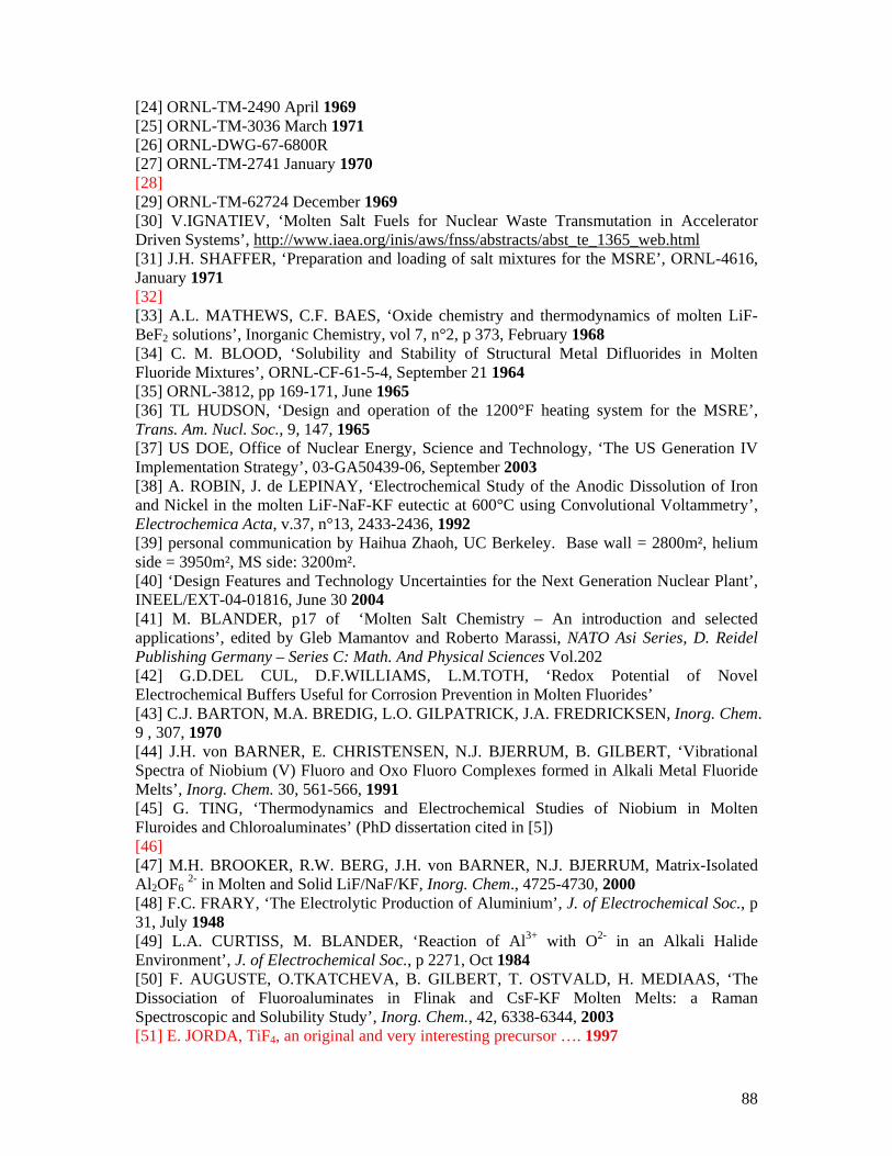
88
[24] ORNL-TM-2490 April 1969 [25] ORNL-TM-3036 March 1971 [26] ORNL-DWG-67-6800R [27] ORNL-TM-2741 January 1970 [28] [29] ORNL-TM-62724 December 1969 [30] V.IGNATIEV, ‘Molten Salt Fuels for Nuclear Waste Transmutation in Accelerator Driven Systems’, http://www.iaea.org/inis/aws/fnss/abstracts/abst_te_1365_web.html [31] J.H. SHAFFER, ‘Preparation and loading of salt mixtures for the MSRE’, ORNL-4616, January 1971 [32] [33] A.L. MATHEWS, C.F. BAES, ‘Oxide chemistry and thermodynamics of molten LiF-BeF2 solutions’, Inorganic Chemistry, vol 7, n°2, p 373, February 1968 [34] C. M. BLOOD, ‘Solubility and Stability of Structural Metal Difluorides in Molten Fluoride Mixtures’, ORNL-CF-61-5-4, September 21 1964 [35] ORNL-3812, pp 169-171, June 1965 [36] TL HUDSON, ‘Design and operation of the 1200°F heating system for the MSRE’, Trans. Am. Nucl. Soc., 9, 147, 1965 [37] US DOE, Office of Nuclear Energy, Science and Technology, ‘The US Generation IV Implementation Strategy’, 03-GA50439-06, September 2003 [38] A. ROBIN, J. de LEPINAY, ‘Electrochemical Study of the Anodic Dissolution of Iron and Nickel in the molten LiF-NaF-KF eutectic at 600°C using Convolutional Voltammetry’, Electrochemica Acta, v.37, n°13, 2433-2436, 1992 [39] personal communication by Haihua Zhaoh, UC Berkeley. Base wall = 2800m², helium side = 3950m², MS side: 3200m². [40] ‘Design Features and Technology Uncertainties for the Next Generation Nuclear Plant’, INEEL/EXT-04-01816, June 30 2004 [41] M. BLANDER, p17 of ‘Molten Salt Chemistry – An introduction and selected applications’, edited by Gleb Mamantov and Roberto Marassi, NATO Asi Series, D. Reidel Publishing Germany – Series C: Math. And Physical Sciences Vol.202 [42] G.D.DEL CUL, D.F.WILLIAMS, L.M.TOTH, ‘Redox Potential of Novel Electrochemical Buffers Useful for Corrosion Prevention in Molten Fluorides’ [43] C.J. BARTON, M.A. BREDIG, L.O. GILPATRICK, J.A. FREDRICKSEN, Inorg. Chem. 9 , 307, 1970 [44] J.H. von BARNER, E. CHRISTENSEN, N.J. BJERRUM, B. GILBERT, ‘Vibrational Spectra of Niobium (V) Fluoro and Oxo Fluoro Complexes formed in Alkali Metal Fluoride Melts’, Inorg. Chem. 30, 561-566, 1991 [45] G. TING, ‘Thermodynamics and Electrochemical Studies of Niobium in Molten Fluroides and Chloroaluminates’ (PhD dissertation cited in [5]) [46] [47] M.H. BROOKER, R.W. BERG, J.H. von BARNER, N.J. BJERRUM, Matrix-Isolated Al2OF6 2- in Molten and Solid LiF/NaF/KF, Inorg. Chem., 4725-4730, 2000 [48] F.C. FRARY, ‘The Electrolytic Production of Aluminium’, J. of Electrochemical Soc., p 31, July 1948 [49] L.A. CURTISS, M. BLANDER, ‘Reaction of Al3+ with O2- in an Alkali Halide Environment’, J. of Electrochemical Soc., p 2271, Oct 1984 [50] F. AUGUSTE, O.TKATCHEVA, B. GILBERT, T. OSTVALD, H. MEDIAAS, ‘The Dissociation of Fluoroaluminates in Flinak and CsF-KF Molten Melts: a Raman Spectroscopic and Solubility Study’, Inorg. Chem., 42, 6338-6344, 2003 [51] E. JORDA, TiF4, an original and very interesting precursor …. 1997
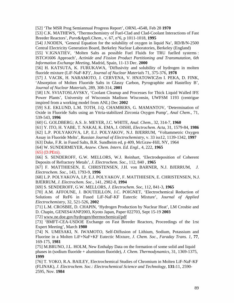
89
[52] ‘The MSR Prog Semiannual Progress Report’, ORNL-4548, Feb 28 1970 [53] C.K. MATHEWS, ‘Thermochemistry of Fuel-Clad and Clad-Coolant Interactions of Fast Breeder Reactors’, Pure&Appli.Chem., v. 67, n°6, p 1011-1018, 1995 [54] J.NODEN, ‘General Equation for the solubility of oxygen in liquid Na’, RD/B/N-2500 Central Electricity Generation Board, Berkeley Nuclear Laboratories, Berkeley (England) [55] V.IGNATIEV, ‘Molten Salts as possible Fuel Fluids for TRU fuelled systems : ISTC#1606 Approach’, Actinide and Fission Product Partitioning and Transmutation, 6th Information Exchange Meeting, Madrid, Spain, 11-13 Dec. 2000 [56] H. KATSUTA, K. FURUKAWA, ‘Diffusivity and solubility of hydrogen in molten fluoride mixture (LiF-NaF-KF)’, Journal of Nuclear Materials 71, 375-376, 1978 [57] J. VACIK, H. NARAMOTO, J. CERVENA, V. HNATOWICZm I. PEKA, D. FINK, ‘Absorption of Molten Fluoride Salts in Glassy Carbon, Pyrographite and Hastelloy B’, Journal of Nuclear Materials, 289, 308-314, 2001 [58] I.N. SVIATOSLAVSKY, ‘Coolant Cleanup and Processes for Thick Liquid Walled IFE Power Plants’, University of Wisconsin Madison Wisconsin, UWFSM 1193 (centrigue inspired from a working model from ANL) Dec 2002 [59] S.E. EKLUND, L.M. TOTH, J.Q. CHAMBERS, G. MAMANTOV, ‘Determination of Oxide in Fluoride Salts using an Yttria-stabilized Zirconia Oxygen Pump’, Anal Chem., 71, 539-543, 1996 [60] G. GOLDBERG; A.S. Jr. MEYER, J.C. WHITE, Anal. Chem., 32, 314-7, 1960 [61] Y. ITO, H. YABE, T. NAKAI, K. EMA, J. OISHI, Electrochem. Acta, 31, 1579-84, 1986 [62] L.P. POLYAKOVA, LP, E.J. POLYAKOV, N.J. BJERRUM, ‘Voltammetric Oxygen Assay in Fluoride Melts’, Russian Journal of Electrochemistry, v. 33 iss12, 1139-1342, 1997 [63] Duke, F.R. in Fused Salts, B.R. Sundheim ed, p 409, McGraw-Hill, NY, 1964 [64] W. SUNDERMEYER, Anzew. Chem. Intern. Ed. Engl., 4, 222, 1965 [65] (D.PEtti). [66] S. SENDEROFF, G.W. MELLORS, W.J. Reinhart, ‘Electrodeposition of Coherent Deposits of Refractory Metals’, J. Electrochem. Soc., 112, 840 , 1965 [67] F. MATTHIESEN, E. CHRISTENSEN, J.H. von BARNER, N.J. BJERRUM, J. Electrochem. Soc., 143, 1793-9, 1996 [68] L.P. POLYAKOVA, LP, E.J. POLYAKOV, F. MATTHIESEN, E. CHRISTENSEN, N.J. BJERRUM, J. Electrochem. Soc., 141, 2982-8, 1994 [69] S. SENDEROFF, G.W. MELLORS, J. Electrochem. Soc, 112, 841-3, 1965 [70] A.M. AFFOUNE, J. BOUTEILLON, J.C. POIGNET, ‘Electrochemical Reduction of Solutions of ReF6 in Fused LiF-NaF-KF Eutectic Mixture’, Journal of Applied Electrochemistry, 32, 521-526, 2002 [71] L.M. CROSBIE, D. CHAPIN, ‘Hydrogen Production by Nuclear Heat’, LM Crosbie and D. Chapin, GENES4/ANP2003, Kyoto Japan, Paper 022703, Sept 15-19 2003 [72] www.ne.doe.gov/hydrogen/thermochemical/pdf [73] ‘BMFT-CEA-USDOE Exchange on Fast Breeder Reactors, Proceedings of the 1rst Expert Meeting’, March 1980 [74] N. UMESAKI, N. IWAMOTO, Self-Diffusion of Lithium, Sodium, Potassium and Fluorine in a Molten LiF+NaF+KF Eutectic Mixture, J. Chem. Soc., Faraday Trans. 1, 77, 169-175, 1981 [75] M.BRUNO, J.L. HOLM, New Enthalpy Data on the formation of some solid and liquid phases in (sodium fluoride + aluminium fluoride), J. Chem. Thermodynamics, 31, 1369-1375, 1999 [76] T. YOKO, R.A. BAILEY, Electrochemical Studies of Chromium in Molten LiF-NaF-KF (FLINAK), J. Electrochem. Soc.: Electrochemical Science and Technology, 131:11, 2590-2595, Nov. 1984
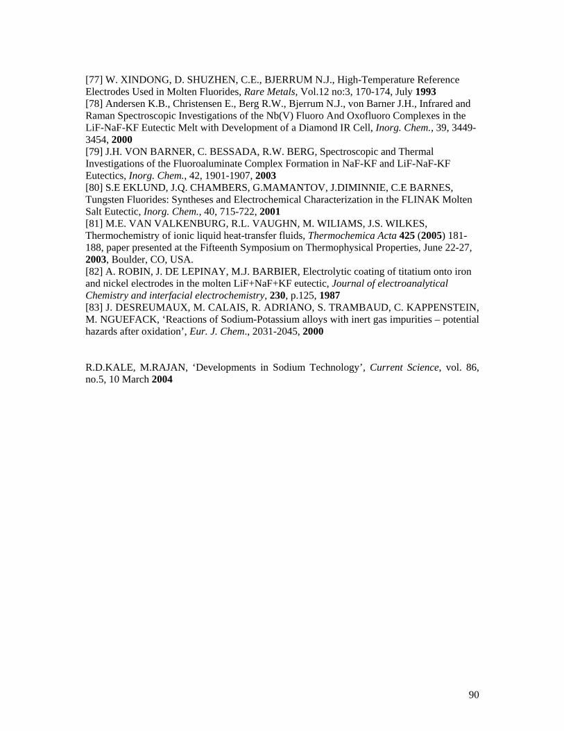
90
[77] W. XINDONG, D. SHUZHEN, C.E., BJERRUM N.J., High-Temperature Reference Electrodes Used in Molten Fluorides, Rare Metals, Vol.12 no:3, 170-174, July 1993 [78] Andersen K.B., Christensen E., Berg R.W., Bjerrum N.J., von Barner J.H., Infrared and Raman Spectroscopic Investigations of the Nb(V) Fluoro And Oxofluoro Complexes in the LiF-NaF-KF Eutectic Melt with Development of a Diamond IR Cell, Inorg. Chem., 39, 3449-3454, 2000 [79] J.H. VON BARNER, C. BESSADA, R.W. BERG, Spectroscopic and Thermal Investigations of the Fluoroaluminate Complex Formation in NaF-KF and LiF-NaF-KF Eutectics, Inorg. Chem., 42, 1901-1907, 2003 [80] S.E EKLUND, J.Q. CHAMBERS, G.MAMANTOV, J.DIMINNIE, C.E BARNES, Tungsten Fluorides: Syntheses and Electrochemical Characterization in the FLINAK Molten Salt Eutectic, Inorg. Chem., 40, 715-722, 2001 [81] M.E. VAN VALKENBURG, R.L. VAUGHN, M. WILIAMS, J.S. WILKES, Thermochemistry of ionic liquid heat-transfer fluids, Thermochemica Acta 425 (2005) 181-188, paper presented at the Fifteenth Symposium on Thermophysical Properties, June 22-27, 2003, Boulder, CO, USA. [82] A. ROBIN, J. DE LEPINAY, M.J. BARBIER, Electrolytic coating of titatium onto iron and nickel electrodes in the molten LiF+NaF+KF eutectic, Journal of electroanalytical Chemistry and interfacial electrochemistry, 230, p.125, 1987 [83] J. DESREUMAUX, M. CALAIS, R. ADRIANO, S. TRAMBAUD, C. KAPPENSTEIN, M. NGUEFACK, ‘Reactions of Sodium-Potassium alloys with inert gas impurities – potential hazards after oxidation’, Eur. J. Chem., 2031-2045, 2000 R.D.KALE, M.RAJAN, ‘Developments in Sodium Technology’, Current Science, vol. 86, no.5, 10 March 2004
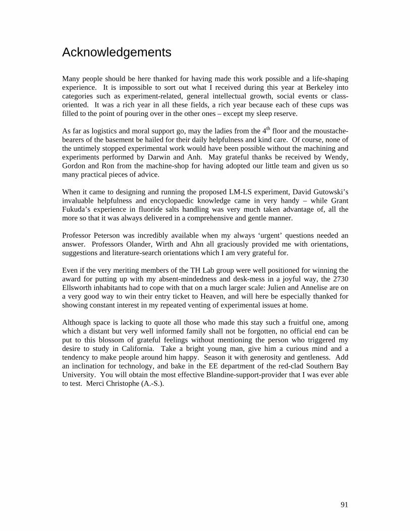
91
Acknowledgements Many people should be here thanked for having made this work possible and a life-shaping experience. It is impossible to sort out what I received during this year at Berkeley into categories such as experiment-related, general intellectual growth, social events or class-oriented. It was a rich year in all these fields, a rich year because each of these cups was filled to the point of pouring over in the other ones – except my sleep reserve. As far as logistics and moral support go, may the ladies from the 4th floor and the moustache-bearers of the basement be hailed for their daily helpfulness and kind care. Of course, none of the untimely stopped experimental work would have been possible without the machining and experiments performed by Darwin and Anh. May grateful thanks be received by Wendy, Gordon and Ron from the machine-shop for having adopted our little team and given us so many practical pieces of advice. When it came to designing and running the proposed LM-LS experiment, David Gutowski’s invaluable helpfulness and encyclopaedic knowledge came in very handy – while Grant Fukuda’s experience in fluoride salts handling was very much taken advantage of, all the more so that it was always delivered in a comprehensive and gentle manner. Professor Peterson was incredibly available when my always ‘urgent’ questions needed an answer. Professors Olander, Wirth and Ahn all graciously provided me with orientations, suggestions and literature-search orientations which I am very grateful for. Even if the very meriting members of the TH Lab group were well positioned for winning the award for putting up with my absent-mindedness and desk-mess in a joyful way, the 2730 Ellsworth inhabitants had to cope with that on a much larger scale: Julien and Annelise are on a very good way to win their entry ticket to Heaven, and will here be especially thanked for showing constant interest in my repeated venting of experimental issues at home. Although space is lacking to quote all those who made this stay such a fruitful one, among which a distant but very well informed family shall not be forgotten, no official end can be put to this blossom of grateful feelings without mentioning the person who triggered my desire to study in California. Take a bright young man, give him a curious mind and a tendency to make people around him happy. Season it with generosity and gentleness. Add an inclination for technology, and bake in the EE department of the red-clad Southern Bay University. You will obtain the most effective Blandine-support-provider that I was ever able to test. Merci Christophe (A.-S.).


![1 O~-'lS''lS'~n~o RtClifIfCJlf Nen9,{k · ::JI1rm:;;:n']lm~:ui'lliII~"'-t~~ RtClifIfCJlf Visit'[jNen9,{k J . o~-'lS''lS'~~'lS'~~ ~: 1](https://img.pdfslide.net/doc/110x75/60405355d11b0d36121b4a37/1-o-lslsno-rtclififcjlf-nen9k-ji1rmnlmuilliii-t-rtclififcjlf.jpg)


![ifjogu€¦ · iwoZ&visf{kr gSaA ifjogu (Transport) LFky ifjogu Hkkjr fo'o osQ lokZfèkd lM+d tky okys ns'kksa esa ls,d gS] ;g lM+d tky yxHkx 54-7 yk[k fdeh- gSA Hkkjr esa lM+d ifjogu]](https://img.pdfslide.net/doc/110x75/5f0dc7b67e708231d43c0c90/ifjogu-iwozvisfkr-gsaa-ifjogu-transport-lfky-ifjogu-hkkjr-foo-osq-lokzfkd.jpg)

![Haryana Government Gazette · ,d fxzM&vk;ju iz.kkyh gS] tks ekStwnk lM+d inkuqØe ds lkFk vPNh rjg ls ,dhd`r gSA ukjukSan ls] ukjukSan&gkalh vkSj ukjukSan&thUn vuqlwfpr lM+d gSA fdlh](https://img.pdfslide.net/doc/110x75/5fd6e6a9daee7052421d86fb/haryana-government-gazette-d-fxzmvkju-izkkyh-gs-tks-ekstwnk-lmd-inkuqe.jpg)