Embed Size (px)
Citation preview

TRANSPORT RESEARCH LABORATORY
The long term performance of embeddedretaining walls
Prepared for Quality Services (Civil Engineering), Departmentof the Environment, Transport and the Regions
D R Carder and P Darley
TRL REPORT 381

Transport Research Foundation Group of CompaniesTransport Research Foundation (a company limited by guarantee) trading as TransportResearch Laboratory. Registered in England, Number 3011746.
TRL Limited. Registered in England, Number 3142272.Registered Offices: Old Wokingham Road, Crowthorne, Berkshire, RG45 6AU.
First Published 1998ISSN 0968-4107
Copyright Transport Research Laboratory 1998.
This report has been produced by the Transport ResearchLaboratory, under/as part of a Contract placed by the Departmentof the Environment, Transport and the Regions. Any viewsexpressed are not necessarily those of the Department.
TRL is committed to optimising energy efficiency, reducingwaste and promoting recycling and re-use. In support of theseenvironmental goals, this report has been printed on recycledpaper, comprising 100% post-consumer waste, manufacturedusing a TCF (totally chlorine free) process.

CONTENTS
Page
Executive Summary 1
1 Introduction 3
2 Embedded walls instrumented during construction 3
2.1 Cut-and-cover tunnels 3
2.1.1 Bell Common tunnel 3
2.1.2 Finchley tunnel 4
2.2 Walls propped at carriageway level 6
2.2.1 Walthamstow bored pile wall 6
2.2.2 Rayleigh Weir bored pile wall 8
2.2.3 A406/A10 Junction diaphragm wall 11
2.2.4 Walthamstow diaphragm wall 11
2.2.5 Hackney to M11 Link bored pile wall 16
2.2.6 Aldershot Road underpass diaphragm wall 16
2.3 Cantilever wall at Finchley 21
3 Embedded walls instrumented whilst in service 21
3.1 Cantilever diaphragm wall at Reading 21
3.2 Propped bored pile wall at New Malden 27
3.3 Anchored diaphragm wall at Neasden 27
4 Conclusions 30
5 Acknowledgements 32
6 References 32
Abstract 33
Related publications 33
iii

iv

1
Executive Summary
Much of the urban development in the UK is founded onheavily overconsolidated sedimentary clays, which areparticularly susceptible to swelling and softeningfollowing the reduction in stress caused by retaining wallconstruction. Moreover, the low permeability of theseclays means the swelling and softening is likely to extendover many years or decades following completion ofconstruction. For these reasons, design of embedded wallsfor long term stability may be critical. This reportdescribes the results from continued monitoring overmany years of various embedded retaining structuresinstrumented by TRL.
The report covers walls instrumented duringconstruction where monitoring has been continued in thelonger term. It also covers walls constructed between 1972and 1975 and instrumented whilst in service to evaluatetheir long term behaviour.
For the walls instrumented during construction,comprehensive data on wall movements and bendingmoments, ground stresses and porewater pressures,together with prop loads, are generally available.Information on the walls in service is more limited andtends to focus on ground stresses and porewater pressures.The report covers cantilever walls, walls propped atcarriageway level, anchored walls and cut-and-covertunnels.
One of the main design uncertainties is the magnitudeof heave which will occur below the new carriageway inthe longer term due to the unloading caused byexcavation. Heave measurements at Bell Common tunnelare reported over an 11 year period of monitoring.
Measurements of anchor head load on under-reamedanchors founded in clay at Neasden are reported over a 24year period since construction and show the anchors areperforming satisfactorily.

2

3
1 Introduction
Over the last two decades, a major programme of researchhas been carried out at TRL for the Highways Agency intothe behaviour of earth retaining structures for roadschemes, with the aim of improving their design andconstruction. The current focus of attention on the needfor highways within built-up areas, and the roadconstruction below ground level that these usually entail,means that this database of research information is nowbeing used extensively in the design of retained cutting,cut-and-cover tunnels, and bridge abutments in the UK.Guidance on the design of embedded walls based on TRLresearch is given in BD 42 (DMRB 2.1).
Particular problems in embedded wall design arise whenthey are founded in heavily overconsolidated claysbecause of the presence of high in situ lateral stresses.These stresses produce high structural loading on the walland any associated propping system, and also render theclays susceptible to swelling and softening followingexcavation. Furthermore, as the clays are of lowpermeability and water percolation is therefore very slow,it may take many decades to reach equilibrium under thenew stress regime caused by construction.
This report discusses the results from TRL sitemonitoring of embedded retaining walls founded in stiffclay carried out to develop a better understanding of longterm behaviour. The studies fall into two categories:
� Embedded walls instrumented at the time ofconstruction where measurements have been continuedfor a number of years. Six walls which are permanentlypropped at carriageway level, one cantilever wall andtwo cut-and-cover tunnels are included in this category.
� Walls constructed between 1972 and 1975 andinstrumented whilst in service to evaluate long termbehaviour. Three different types of wall have beeninvestigated, ie. cantilever, permanently propped atcarriageway level, and anchored.
For the walls instrumented during construction,comprehensive data on wall movements and bendingmoments, ground stresses and porewater pressures,together with prop loads are generally available.Information on the walls in service is more limited andtends to focus on ground stresses and porewater pressures.
2 Embedded walls instrumented duringconstruction
Detailed results on the performance of the instrumentedwalls during construction have already been reported andrecourse should therefore be made to the appropriatesource reference. A summary of the measurements at thevarious sites of wall and ground movements oncompletion of construction has been produced by Carder(1995). This report now deals with the longer term changeswhich have occurred since construction ended.
2.1 Cut-and-cover tunnels
2.1.1 Bell Common tunnelIn 1982-83 a 475m long cut-and-cover tunnel wasconstructed at Bell Common to carry the M25 through thenorthern edge of Epping Forest. The tunnel was formed fromtwo secant pile walls founded in London Clay and proppedapart by a roofing slab which was simply supported on thewalls and on a central line of piles. A section of the tunnelwas extensively instrumented to measure the stresses on, andmovement of, the wall and the adjacent ground movements(Tedd et al, 1984). The field measurements drew attention tothe substantial ground movements which can occur duringthe installation of an embedded wall: these wereaccompanied by significant reductions in the total lateralstress in the ground close to the wall. The magnitude andextent of these movements and stress changes wheninstalling an embedded wall will be highly dependent on theground conditions and the method of construction; theprocess of wall installation is an essential component of theoverall construction sequence which generally needs to besimulated carefully in a numerical analysis to obtain areliable prediction of performance.
At Bell Common, a finite element prediction ofbehaviour (Potts and Burland, 1983) was carried out priorto construction based on published stiffness properties ofthe clay derived from previous back-analyses.Discrepancies between the predicted and measured wallbending moments were accounted for by the combinedstiffness of the roofing slab and compressible packingbeing less than assumed, the process of wall installationnot being modelled, and the excavation sequence varyingfrom that used in the analysis. Further finite elementanalyses (Higgins et al, 1989) were therefore carried outwhich took these factors into account and utilised soilstiffnesses derived from laboratory tests where the stresspaths of the soil in the vicinity of the wall were accuratelyfollowed. The revised prediction gave better agreementwith the measurements when comparing the bendingmoments in the upper part of the wall, but over-predictedthe magnitude of moments at greater depth.
Measurements taken 4 years after the end ofconstruction have been reported by Symons and Tedd(1989) who concluded that there was little indication ofany significant change in lateral earth pressure in theLondon Clay behind the wall while, in front of the wall,earth pressures reduced by only a small amount. Thechanges in wall deflected shape suggested that there hasbeen a reduction in the propping action of the roof slabpossibly due to time dependent stress-strain properties ofthe compressible packing installed between the roof andthe wall. The changes in lateral movement of the wall overa 9 year period following the end of construction areshown in Figure 1. Generally only small changes weremeasured after the reading taken in May 1988 and, after afurther 4 years, movement at the top of the wall record inJuly 1992 indicated only a 2mm difference.
The wall movements appeared to have occurredprimarily by rotation and there was little evidence of anytranslation of the wall toe in the longer term. This

4
conclusion was verified by the tape extensometermeasurements in Figure 2 of convergence inside thetunnel between the secant pile wall and the centraldividing line of piles. Also shown in Figure 2 is themovement at 6.7m depth measured using the inclinometertube in the secant pile wall. The reasonable correlationbetween the results would not exist if any significantmovement of the toe of the wall were occurring. Theresults in Figure 2, particularly the earlier results wherereadings were taken more frequently, also show somesmall seasonal fluctuations which are probably a result ofthermal expansion and contraction of the roof slab.
For walls founded in stiff clay, one of the major designuncertainties is the magnitude of heave which will occurbelow the new carriageway in the longer term due to theunloading caused by bulk excavation. Measurements atBell Common tunnel are unique in so far ascomprehensive monitoring of clay heave was undertaken.Figure 3 shows the heave measured at 1.5m depth acrossthe carriageway using seven settlement cells. These cellswere installed on completion of bulk excavation and, after11 years in service, a maximum heave of nearly 50mm wasmeasured at 10.5m away from the wall, ie. atapproximately midway between the tunnel wall and the
central supporting line of piles. Examination of the resultsin Figure 3 indicates that little or no further heave hasoccurred in the last few years and this is confirmed by thetime plots of subsurface heave given in Figure 4.
The subsurface heave measurements were carried out usinga magnetic extensometer system installed in a borehole at9.3m distance from the wall (Tedd et al, 1984). As with thesettlement cells, the instruments were installed shortly afterbulk excavation was completed. The measurements in Figure4 indicate an approximately linear reduction in heave withdepth at all stages and also confirmed that the major part ofthe heave occurred within the first 3 or 4 years after bulkexcavation. Since then the rate of increase of heave with timehas slowed and an essentially stable situation has beenreached after about 10 years.
2.1.2 Finchley tunnelIn 1995 field instrumentation was installed to investigatethe performance of the diaphragm walls of a cut-and-covertunnel during its construction at the junction of the A406North Circular Road and Old East End Road, Finchley. Thetunnel traverses a Boulder Clay outlier underlain byLondon Clay at a maximum depth of 23m, with asubstantial gravel layer at the interface. The tunnel was
Figure 1 Long term wall movements at Bell Common tunnel
0 5 10 15 20 25 30 35
0
5
10
15
20
Lateral movement towards excavation (mm)
Dep
th (
m)
Oct '83 May '87 May '88
April '90 June '91 July '92
End of construction: June '83
Formation level

5
Figure 2 Convergence across eastbound carriageway at Bell Common tunnel
Figure 3 Heave at 1.5m below the carriageway at Bell Common tunnel
1982 1984 1986 1988 1990 1992 1994
-3
-2
-1
0
1
2
3
4
Year
Con
verg
ence
(m
m)
Taping
Inclinometer
End of construction: June '83
0 2 4 6 8 10 12 14
0
10
20
30
40
50
60
Distance from wall (m)
Hea
ve (
mm
)
July '85 May '87 June '90 July '92 May '94
End of construction: June '83

6
constructed top-down with an integral roof slab installedbetween the planar diaphragm walls prior to bulkexcavation and the construction of a structural carriagewayslab. In addition to monitoring lateral movements andbending moments developed in the wall duringconstruction, axial loads in the roof and carriageway propslab were also measured. The field data covering six monthsafter the completion of tunnel construction were reported byBrookes and Carder (1996a).
Figure 5 shows the lateral movements of the wall andretained ground measured using an inclinometer systemduring construction and the 18 months following bulkexcavation. Only a small additional lateral movement ofabout 1mm was measured close to the top of the wallduring this period. No significant changes were measuredusing the ground inclinometer tube at 1.9m from the wall.
A feature of the construction reported by Brookes andCarder (1996a) was the high initial axial load in the roofof about 1000kN/m, whilst no significant loads wererecorded in the permanent structural slab forming thetunnel carriageway. If temporary props had been employedat a lower level during construction, their removal wouldprobably have pre-loaded the carriageway prop to someextent and resulted in lower roof loads. Figure 6 shows thelonger term changes in axial loads in the tunnel roofmeasured by the strain gauges. There is some evidence of
the high roof loads reducing with time and this reductionhas been accompanied by a small increase in the load inthe carriageway prop to a mean value of no more than160kN/m.
Figure 7 shows that there is little change in the bendingmoments in the tunnel roof from the values reported byBrookes and Carder (1996a) at the end of construction.The results do however demonstrate a reduction inbending moments when the spoil on top of the roof wasremoved and a subsequent increase when fill was placedafter waterproofing the deck.
2.2 Walls propped at carriageway level
2.2.1 Walthamstow bored pile wallA contiguous bored pile retaining wall founded in stiffLondon Clay was constructed in 1991 as part of the A406North Circular Road improvement scheme betweenChingford Road and Hale End Road in Walthamstow.Field monitoring was carried out to measure movements,total lateral stresses and porewater pressures in the groundbehind and in front of the wall. The performance of thestructural members was also monitored by measuring wallmovements and bending moments together with loads inthe permanent hinged prop at carriageway level. Carswellet al (1993) presented the results for the wall installation
Figure 4 Subsurface heave below carriageway at 9.3m from wall at Bell Common tunnel
1982 1984 1986 1988 1990 1992 1994
0
10
20
30
40
50
Year
Hea
ve (
mm
)
1.65m depth 5.65m depth 9.65m depth 13.65m depth
Road opened

7
Figure 5 Wall and ground movements during tunnel construction at Finchley
Figure 6 Development of axial load in the tunnel roof at Finchley
0 1 2 3 4 5 6
0
5
10
15
20
25
Lateral movement towards excavation (mm)
Dep
th (
m)
0 1 2 3 4 5 6
0
5
10
15
20
25
Lateral movement towards excavation (mm)
Dep
th (
m)
11
1
2
2
- Excavation to 3.5m depth
- After roof installation and excavation to formation (9m depth)
Ground inclinometer I1(1.9m from wall)
Wall inclinometersI 2I 3
2
3 - 18 months later
3 3
200 400 600 800 1000 12000
200
400
600
800
1000
1200
1400
Day number
Axi
al lo
ad (
kN/m
)
Excavation complete
Distance of gauges from wall :-
2.98m1.92m1.02m
to formation level
Roof slab cast on day 198

8
stage, underpass construction and the six monthsfollowing opening of the road to traffic.
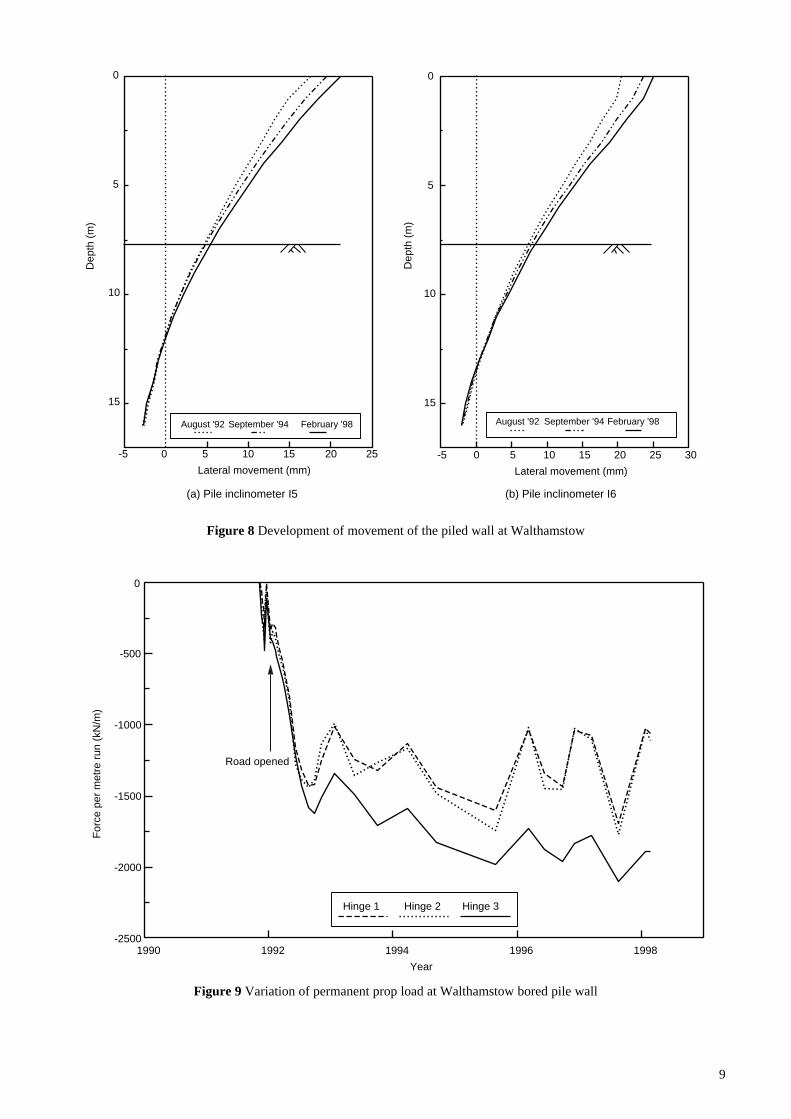
Generally no significant changes have been recorded inthe total lateral stresses and porewater pressures close tothe wall over the following 5 years and results aretherefore similar to those reported by Carswell et al (1993).However some small additional movements of the wallhave occurred and these are shown in Figure 8. In thisfigure, inclinometer readings have been corrected byelectronic distance measurements (Geomensor) to the topof the wall. Measurements on both inclinometer tubes I5and I6 indicate a further outward rotational movementabout the permanent prop slab of about 2mm at the top ofthe wall between August 1992 and September 1994. Theresults confirm that there has been no translation of the toeof the wall in the 2 year period up to September 1994.Further measurements in the 4 year period up to February1998 show the same trend continuing for bothinclinometer tubes I5 and I6, ie. no translation of the toeand a further small outward movement of the top of thewall of about 1.5mm. Over the 6 years in service, there isno indication of any significant outward translation of thetoe which might be expected because of longer termconsolidation effects (Watson and Carder, 1994).
Longer term variations in permanent prop loadmeasured using vibrating wire strain gauges in threeadjacent hinges are shown in Figure 9. Generally aseasonal variation in prop load consistent with thermalexpansion and contraction of the slab was recorded.Particularly noticeable are the peaks in the compressiveloads monitored towards the end of the hot summers of1995 and 1997. The underlying trend of the results
suggests that the gradual increase in prop load measuredover the first 3 years in service has slowed and that themain changes are now thermal effects.
Watson and Carder (1994) carried out finite elementmodelling which indicated that measured and predictedbending moments in the wall were broadly similar at thevarious stages of construction. The results in Figure 10indicate that wall bending moments have increased duringthe 6 years since the road was opened. However themaximum moment of 570kNm/m measured at permanentprop level is still well below the 1750kNm/m calculated onthe basis of the total lateral stresses measured at 1.1mbehind the wall ( ie. a K value of about 1). This discrepancyindicates that some further relief of lateral stress in theretained ground has occurred very close to the wall.
2.2.2 Rayleigh Weir bored pile wallAt this site in Essex, the contiguous bored pile wallfounded in London Clay was allowed to cantileveroutwards during bulk excavation to 3m above final dredgelevel: temporary props were then installed for theremainder of the excavation and permanent propconstruction. This procedure relieved lateral stress on theretained side of the wall and permitted the use of a massconcrete rather than a reinforced concrete prop slab atcarriageway level. Monitoring of ground and waterpressures, wall movements and bending moments,temporary and permanent prop loads, was carried outduring construction and in the following 10 months untilJuly 1992 and was reported by Darley et al (1994).
Continued monitoring of spade pressure cells and
Figure 7 Development of bending moment in the tunnel roof at Finchley
0 200 400 600 800 1000 1200 1400-100
0
100
200
300
400
500
Day number
Ben
ding
mom
ent (
kNm
/m)
Excavation complete
Distance of gauges from wall :-
2.98m1.92m1.02m
to formation level
Roof slab cast on day 198
Spoil placed ontunnel roof
Spoil removed
Fill placed afterwaterproofing deck
9
Figure 9 Variation of permanent prop load at Walthamstow bored pile wall
Figure 8 Development of movement of the piled wall at Walthamstow
-5 0 5 10 15 20 25
0
5
10
15
Lateral movement (mm)
Dep
th (
m)
August '92 September '94 February '98
-5 0 5 10 15 20 25 30
0
5
10
15
Lateral movement (mm)
Dep
th (
m)
August '92 September '94 February '98
(a) Pile inclinometer I5 (b) Pile inclinometer I6
1990 1992 1994 1996 1998-2500
-2000
-1500
-1000
-500
0
Year
For
ce p
er m
etre
run
(kN
/m)
Hinge 1 Hinge 2 Hinge 3
Road opened

10
piezometers over a 3 year period from the last reporteddata indicated that no significant changes had occurred inthe total lateral stresses and porewater pressures in theground close to both sides of the wall.
Lateral movements of the bored pile wall weredetermined from inclinometer surveys on a tube in the walland Geomensor electronic distance measurements to the topof the wall: the results are shown in Figure 11. Movementsevaluated in April 1995, about 3½ years after constructionended, were within the cluster of results obtained during theinitial 10 months in service. It was therefore evident that,within the accuracies of measurement and allowing forsome seasonal variations, little or no movement hadoccurred over the 3½ year period.
Vibrating wire strain gauges were installed both withinthe thrust blocks for the permanent prop slab and withinthe bored pile wall. Readings from these instrumentsindicated that changes had occurred over the monitoring
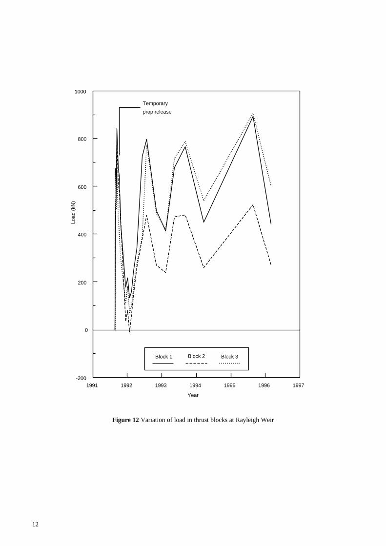
period. Variation of axial loads in the thrust blocks areshown in Figure 12 (page 12). Generally the resultsindicated a seasonal thermal effect with load increasing inthe summer months and decreasing in the winter; thisbehaviour was consistent with thermal expansion andcontraction of the concrete of the prop slab. Peak loads ofabout 900kN were measured on thrust blocks 1 and 3 at theend of the hot summer of 1995. These loads correspondedto a value of 176kN per metre run of the wall.
The changes in wall bending moment calculated fromthe strain gauges are shown in Figure 13 (page 13). Thelast results reported by Darley et al (1994) were for June1992 and since then an increase in bending moment hasoccurred in the upper part of the wall. This increasemainly developed over the winter of 1992 and wasevident in the readings taken in the following March.Since then values have remained fairly constant with apeak of about 500kNm/m at 5.5m depth. This measured
Figure 10 Development of bending moment in the bored piled wall at Walthamstow
0 200 400 600 800 1000-2
0
2
4
6
8
10
12
14
Bending moment (kNm/m)
AO
D (
m)
6 months 3.5 years 6 years
Prop
Time after road opened:

11
Figure 11 Development of movement of the piled wall at Rayleigh Weir
bending moment still remains well below that of830kNm/m calculated for this depth assuming earthpressures corresponding to a K of 1.
2.2.3 A406/A10 Junction diaphragm wallField instrumentation was installed to monitor thebehaviour of a counterforted (T-shaped) diaphragmretaining wall founded in overconsolidated clay during itsconstruction as part of the A406 North Circular Road, GreatCambridge Road Improvement Scheme. The wall wasconstructed with a permanent reinforced concrete prop slabat carriageway level which was hinged at the joints betweenthe prop and the wall. Results during construction and thefirst year of service after the road was opened in February1990 were reported by Carder et al (1991).
Monitoring carried out from 1990 until 1996 showed nosignificant changes in the total lateral stresses and theporewater pressures measured close to the wall on both theretained and excavated sides. Distributions of stress andporewater pressure with depth are therefore as reported byCarder et al (1991).
Figure 14 (page 14) shows the lateral movement of the topof the wall measured over the same period. This shows abroad correlation between the results from electronic distancemeasurements (Geomensor) and those from two separateinclinometer tubes I1 and I2. As the analysis of movementsfrom the inclinometer tubes assumes base fixity, this findingconfirms that little or no movement of the toe of the wall hasoccurred over the 6 year period. Generally the results inFigure 14 also suggest that there is no underlying trend in the
magnitude of wall movements with time. However there is avariation of about ±1.5mm in the movement of the top of thewall and close examination indicates that a small movementtowards the underpass is recorded in winter and the conversein summer. This behaviour is consistent with the thermalcontraction and expansion of the permanent prop slab atcarriageway level which is likely to occur seasonally.
The lateral wall movement profile with depth measuredusing an inclinometer system at 3 yearly intervals isshown in Figure 15 (page 15). The range of measurementsshowed variations of a few millimetres as would beexpected from the results given in Figure 14.
2.2.4 Walthamstow diaphragm wallThis counterforted diaphragm wall was constructed for anunderpass on the A406 North Circular Road improvementscheme in 1991. The underpass was part of the samecontract as the bored pile wall described in Section 2.2.1:however the two locations were about 700m apart. Thewall was founded in London Clay which became stifferwith depth. The clay was encountered to the surfacealthough the upper 8.5m was weathered in nature. Thestructure was propped at carriageway level with precastconcrete hinges at the joints between the slab and the wallto accommodate ground heave during the life of thestructure. Instrumentation was similar to that at the boredpile wall, although measurements of permanent prop loadwere not made at this site. The instrumentation andmonitoring results during construction and the first 3months of service are described by Carder et al (1994).
Toe level
-10 -5 0 5 10 15 20 25 30
0
5
10
15
20
25
Lateral movement towards underpass (mm)
Dep
th (
m)
September '91
December '91
February '92
July '92
April '95
Prop
12
Figure 12 Variation of load in thrust blocks at Rayleigh Weir
1991 1992 1993 1994 1995 1996 1997-200
0
200
400
600
800
1000
Year
Load
(kN
)
Block 1 Block 2 Block 3
Temporary
prop release

13
Figure 13 Development of bending moment in the piled wall at Rayleigh Weir
0 200 400 600 800
0
5
10
15
20
25
Bending moment (kNm/m)
Dep
th (
m)
Sept '91 Jan '92 June '92 March '93 April '95
Prop
Toe level

14
Figure 14 Movement of top of wall at A406/A10
1990 1991 1992 1993 1994 1995 1996 19970
2
4
6
8
10
Year
Late
ral m
ovem
ent t
owar
ds e
xcav
atio
n (m
m)
Geomensor Inclinometer I1 Inclinometer I2

15
Figure 15 Range of movement of the diaphragm wall at A406/A10
0 2 4 6 8
0
2
4
6
8
10
12
14
Lateral movement (mm)
Dep
th (
m)
Nov '90 May '93 Feb '96
Wall inclinometer I1

16
Figure 16 shows the movement of the top of the walldetermined from electronic distance measurements(Geomensor) and from inclinometer surveys assuming basefixity of the tube in the wall. The difference between theresults indicates the magnitude of wall toe movementwhich has occurred. A toe movement towards theunderpass of about 5mm developed primarily during bulkexcavation and, over the 5 year period since the underpasswas opened, very little further movement has developed.The profiles of wall movement with depth measuredbetween 1992 and 1998 are compared in Figure 17. Theresults indicate only a small increase in movement whichmay reflect seasonal changes due to thermal expansionand contraction of the permanent prop slab rather than atrend of increasing lateral movement.
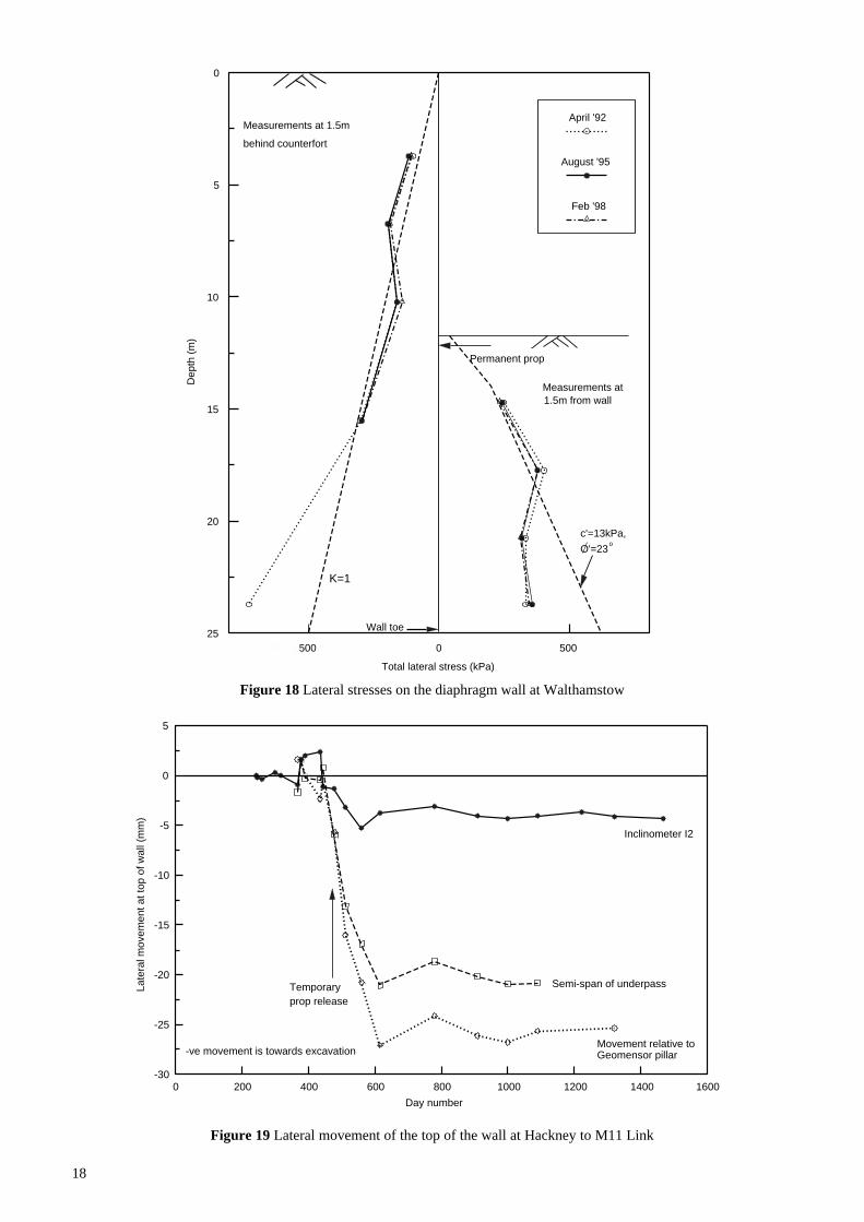
Measurements of total lateral stress acting on both sidesof the wall taken 3 months and nearly 5 years after theopening of the underpass are compared in Figure 18.Results are very similar with only minor redistributions ofstress having occurred. The four uppermost spade cellslocated in the retained ground at 1.5m behind thecounterfort of the T-panels recorded stressescorresponding to a K value of 1. The deepest cell initiallygave higher values in 1992 but has since malfunctioned sothat no further readings are available. The spade cellmeasurements in front of the wall are compared withpassive values calculated using the best fit soil parametersfrom triaxial compression tests of c'=13kPa and φ'=23o.The values of passive earth pressure coefficient have beendetermined assuming a wall friction angle of φ'/2 and zerowall cohesion in accordance with the recommendations ofPadfield and Mair (1984). The measured pressures on theupper two cells were slightly above the K
p value
calculated in this way, although stresses on the deeper twocells were below this K
p.
2.2.5 Hackney to M11 Link bored pile wallThe secant pile wall being investigated forms part of thesouth wall on the George Green tunnel approach which islocated on the new alignment of the A12 to M11 LinkRoad. The secant bored piles were of 1.2m diameter andinstalled at 1m centres; each pile was reinforced by auniversal I-beam (914×305mm, 224kg/m). The wall at theinstrumented section has a nominal retained height of 7.5mand an overall penetration of 18m. The wall was founded inLondon Clay although made ground and sandy gravel(Boyn Hill Gravel) existed to a depth of about 6m from theground surface. Bulk excavation was carried out beneathtemporary steel props which were released after constructionof a permanent reinforced concrete prop slab at carriagewaylevel. The slab was nominally 1m thick and was constructedusing a shear connection between the slab and the wallwhich allowed some rotation to occur thus accommodatinglong term heave of the underlying clay. The fieldinstrumentation and monitoring carried out duringconstruction and the following five months have beenreported by Bennett et al (1996).
Figure 19 shows the lateral movement of the top of thewall obtained using three techniques. The inclinometerresults assume base fixity, which takes no account of any
movement of the toe of the wall. This was assessed usingthe Geomensor electronic distance measuring system intwo ways. Firstly by assuming the reference pillar at 14mfrom the wall remained stationary and secondly bymeasuring the changes in span between the opposingwalls and assuming they moved identically.Measurements in Figure 19 using the latter two techniqueswere not available throughout the period as the sight linesbecame obscured after parapet construction. Readingsusing all three techniques over the 2½ year period sinceconstruction ended (around day 600) indicated very littlechange. The final profile of wall movement with depth istherefore much as reported by Bennett et al (1996) withlateral movements at the top and toe of the wall of no morethan 25mm and 18mm respectively.
The changes in wall bending moment over the sameperiod are shown in Figure 20. These bending momentswere calculated from pairs of strain gauges at variousdepths on the I-beam reinforcement of one of the piles.Generally there were only minor changes in the profilewith depth over the 2½ year period of monitoring. If thebending moments are calculated on the basis of activepressures on the retained side of the wall assuming zerocohesion and φ’ of 36o for the overlying gravel, a peakbending moment of 400kNm/m is determined atcarriageway level. This agrees reasonably with themeasured values shown in Figure 20.
Measurements of lateral stress using spade cells at 1.25mbehind and in front of the wall are given in Figure 21. Verylittle difference existed between the measurements takenin December 1995 (5 months after construction) and muchlater in March 1998. Lateral stresses in the retained claywere generally just below a K value of 2. Stresses on theexcavated side of the wall were below the line calculatedusing best fit soil strength parameters (Bennett et al, 1996)assuming full wall friction and in closer agreement withthat using wall friction of ½φ'.
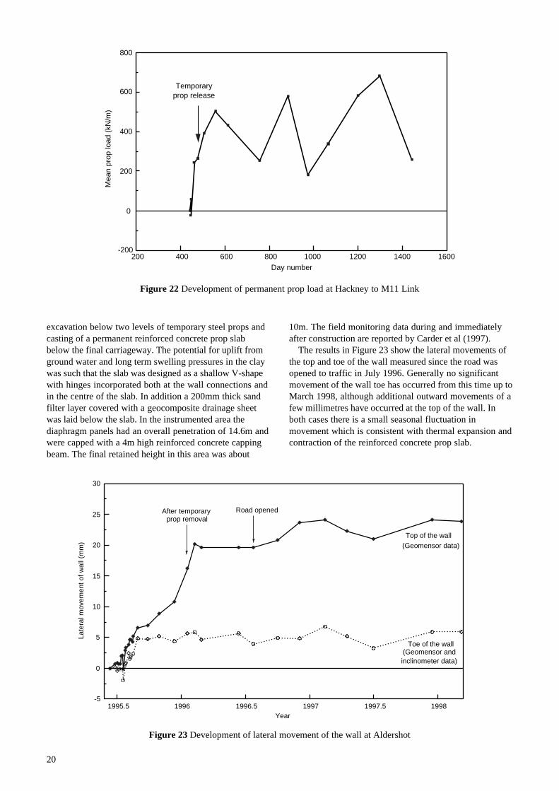
Axial loads in the permanent prop slab were calculatedfrom strain gauge measurements and the variation of meanprop load with time is shown in Figure 22. In commonwith the results from other sites, prop load was found tovary seasonally with the higher loads being recorded dueto prop slab expansion during the summer. Over the periodof measurement, the mean prop load varied between200kN/m and 700kN/m at this site.
The subsurface heave of the clay below the permanentprop slab was monitored using a combination of magnetextensometers and precise levelling. Five months aftercompletion of construction, mean heaves of 19mm, 12mmand 7mm were recorded at 3m, 7m and 10m depths belowthe prop slab. After 2½ years these heaves had increased to26mm, 17mm and 10mm respectively.
2.2.6 Aldershot Road underpass diaphragm wallField instrumentation was installed to monitor thebehaviour of a T-shaped diaphragm retaining wallfounded in overconsolidated London Clay during itsconstruction as part of the Aldershot Road underpass in1995 and 1996. The construction sequence involvedinstallation of the wall under bentonite followed by

17
Figure 16 Movement of top of diaphragm wall at Walthamstow
Figure 17 Lateral movement of the diaphragm wall at Walthamstow
0 5 10 15 20 25
0
5
10
15
20
Lateral movement (mm)
Dep
th (
m)
April '92
March '94
March '96
Feb '98
Wall inclinometer I5
Permanentprop
1992 1994 1996 19980
5
10
15
20
25
Year
Late
ral m
ovem
ent t
owar
ds e
xcav
atio
n (m
m)
Geomensor Inclinometer I5
Underpass opened
18
Figure 18 Lateral stresses on the diaphragm wall at Walthamstow
Figure 19 Lateral movement of the top of the wall at Hackney to M11 Link
-500 0 500
0
5
10
15
20
25
Total lateral stress (kPa)
Dep
th (
m)
April '92
August '95
Feb '98
K=1
Measurements at 1.5m
Measurements at1.5m from wall
Permanent prop
behind counterfort
Wall toe
c'=13kPa,
O'=23o
0 200 400 600 800 1000 1200 1400 1600-30
-25
-20
-15
-10
-5
0
5
Day number
Late
ral m
ovem
ent a
t top
of w
all (
mm
)
Temporaryprop release
-ve movement is towards excavation
Inclinometer I2
Semi-span of underpass
Movement relative toGeomensor pillar

19
Figure 20 Changes in wall bending moment at Hackney to M11 Link
Figure 21 Lateral stress distribution at Hackney to M11 Link
0 100 200 300 400 500 60014
16
18
20
22
24
26
28
30
Bending moment (kNm/m)
AO
D (
m)
December '95
March '98
Permanent
prop
800 600 400 200 0 200 400 600 80010
15
20
25
30
Total lateral stress (kPa)
AO
D (
m)
Wall toe
Permanent prop
December '95
March '98
K=2 K=1
London Clay
δ/O' = 0.5
/ O'=1.0δ
c' = 13 kN/m2, Ο' = 25 o
c' = 13 kN/m2, Ο' = 25 o
20
Figure 22 Development of permanent prop load at Hackney to M11 Link
excavation below two levels of temporary steel props andcasting of a permanent reinforced concrete prop slabbelow the final carriageway. The potential for uplift fromground water and long term swelling pressures in the claywas such that the slab was designed as a shallow V-shapewith hinges incorporated both at the wall connections andin the centre of the slab. In addition a 200mm thick sandfilter layer covered with a geocomposite drainage sheetwas laid below the slab. In the instrumented area thediaphragm panels had an overall penetration of 14.6m andwere capped with a 4m high reinforced concrete cappingbeam. The final retained height in this area was about
10m. The field monitoring data during and immediatelyafter construction are reported by Carder et al (1997).
The results in Figure 23 show the lateral movements ofthe top and toe of the wall measured since the road wasopened to traffic in July 1996. Generally no significantmovement of the wall toe has occurred from this time up toMarch 1998, although additional outward movements of afew millimetres have occurred at the top of the wall. Inboth cases there is a small seasonal fluctuation inmovement which is consistent with thermal expansion andcontraction of the reinforced concrete prop slab.
200 400 600 800 1000 1200 1400 1600-200
0
200
400
600
800
Day number
Mea
n pr
op lo
ad (
kN/m
)
Temporaryprop release
Figure 23 Development of lateral movement of the wall at Aldershot
1995.5 1996 1996.5 1997 1997.5 1998-5
0
5
10
15
20
25
30
Year
Late
ral m
ovem
ent o
f wal
l (m
m)
After temporaryprop removal
Top of the wall(Geomensor data)
Toe of the wall(Geomensor andinclinometer data)
Road opened

21
Five pairs of pressure cells were installed in the sandfilter layer at different distances from the wall to measuretotal vertical stresses below the permanent prop slab. Theaverage results for each pair are shown plotted againsttime in Figure 24. Generally the measured stresses beneaththe western and eastern slabs were lower closer to the wallthan they were further away because more fill was placedtowards the centre of the underpass. A sudden reduction invertical stress was measured on all cells, especially thosenearer the centre of the underpass, when the road wasopened to traffic. It is not clear whether this redistributionof stress due to trafficking was related to the presence ofthe sand and geocomposite layer on which the slab wasseated, or the hinged design of the slab.
Figure 25 shows the subsurface heaves below formationlevel measured using the magnetic ring extensometersystems in conjunction with precise levelling. The detailedlocations of the magnetic rings are described by Carder et al(1997) with the uppermost ring at each location beingbetween 1m and 3m below formation. By the time the roadwas opened to traffic, overall heaves of about 45mm hadbeen recorded on the shallower rings at 6m from both walledge beams. A smaller heave of about 20mm was recordedon the shallow magnetic ring in the centre of the underpass(Figure 25c) and this was because the initial datum readingwas taken after bulk excavation was completed. Whereasthere was little change over the first year in service in heavevalues recorded at 6m from the wall edge beams (Figure 25aand b), measurements on the central magnetic ring system(Figure 25c) suggested that a settlement of about 10mm hadoccurred below the central hinge. This may be related to thefall in vertical stress due to trafficking discussed earlier.
The variations in permanent prop load and temperaturewith time measured using vibrating wire strain gauges andthermistors respectively are shown in Figure 26.Measurements of prop load at this site were unusual in so faras the compressive loads of between 157kN/m and 471kN/mrecorded before opening of the road to traffic have reducedover the first year in service, possibly because of the ‘seating’effects just described. There are now some early signs thatloads are beginning to stabilise and in the longer term anyfurther heave of the clay may result in increases of prop load.
2.3 Cantilever wall at Finchley
This study of the cantilever wall was undertakenconcurrently with an investigation into the performance ofthe cut-and-cover tunnel at the same site: the latter resultshave been discussed in Section 2.1.2. The cantilever wallswere used to flank the approaches to the tunnel, andcomprised 24m deep contiguous bored piles of 1.5mdiameter installed at 1.98m centres. The retained height ofthe wall in the instrumented area was 4.75m. The geology ofthe site was predominantly Boulder Clay, a typicallyheterogenous glacial till comprising stiff clays interspersedwith sand and gravel lenses. Measurements of wallmovement and bending moment were monitored duringconstruction and for a period of about 10 months aftercompletion of construction (Brookes and Carder, 1996b).
Continued monitoring took place over a further 21month period and indicated very little change. Figure 27shows the profiles of lateral movement against depth.
Following bulk excavation in June 1995 the wallcantilevered towards the excavation with a lateralmovement at the top of the wall of about 5mm. Respectivemovements at the top of the wall of 9mm and 11mm wereobserved at 4 and 10 months after excavation. Readingstaken at 31 months after excavation showed nomeasurable change from those recorded at 10 months.Movements at ground surface using a tape extensometersystem showed close agreement throughout with theinclinometer surveys, confirming that no movementoccurred at the base of the pile inclinometer tubes.
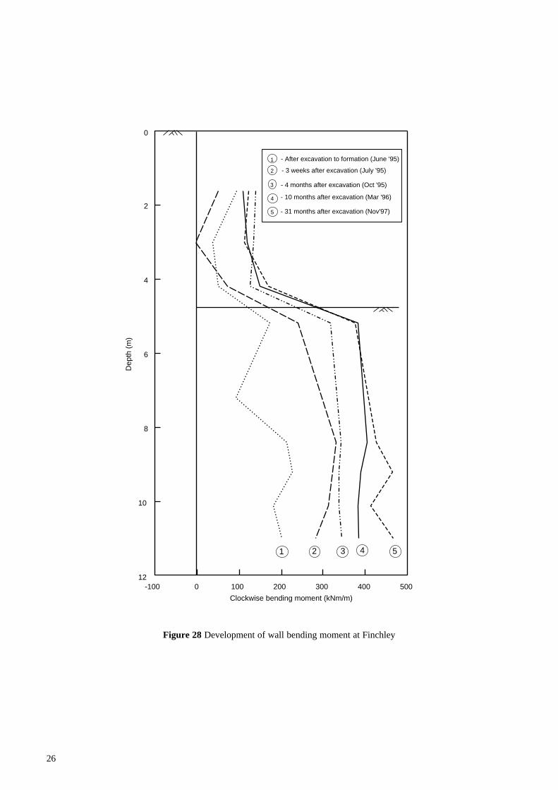
Figure 28 shows the development of wall bendingmoment with time. As would be anticipated from themovement results, no significant change in bendingmoment was measured between 10 and 31 months afterbulk excavation. In Figure 28 the bending moments at 31months after excavation increased with depth to a value ofabout 400kNm/m just below carriageway level. This valuewas more consistent with lateral stresses in the retainedground corresponding to a K value of 1 than with activeearth stresses. This point is discussed in more detail byBrookes and Carder (1996b).
3 Embedded walls instrumented whilstin service
For embedded retaining walls in stiff clay the critical designcondition often occurs in the long term when full porewaterpressure equilibrium has been reached under the new stressregime. Field studies have been undertaken to measure earthand porewater pressures acting on various structural types ofembedded wall which were constructed between 1972 and1975 and therefore have been in service for about twodecades. Data on the performance of a cantilever diaphragmwall, a contiguous bored pile wall propped at carriagewaylevel and an anchored diaphragm wall are now considered.
3.1 Cantilever diaphragm wall at Reading
The diaphragm wall was constructed in 1972 andinstrumentation was installed to establish its long termperformance in 1984. At this site, a layer of terrace graveloverlies the London Clay which extends from a depth of3m to 20m. Below about 14.5m the clay is very stiff, withthin sand bands occurring in places. Instrumentation wasinstalled to monitor the total lateral stress and porewaterpressures both behind and in front of the wall. Results upto 1987 were reported by Carder and Symons (1989a),although monitoring has continued in the longer term.
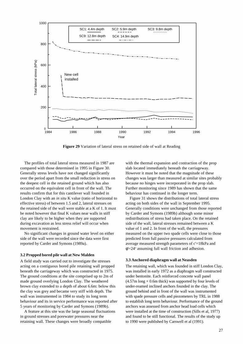
Figure 29 shows the variation of total lateral stress withtime as recorded by push-in spade cells at different depthson the retained side of the wall. Some small readjustmentsin stress were recorded on shallow cells SC1 and SC2:initially SC1 gave the lower values, but by 1995 theconverse was true. Generally however, the only significantchange was the gradual reduction in measured stress withtime on the deepest cell SC4. Carder and Symons (1989a)in interpreting the results recognised that cell SC4 wasgiving a higher value than anticipated possibly becausethe cell was installed in lower plasticity clay.

22
1995.5 1996 1996.5 1997 1997.5 1998 1998.5
0
10
20
30
40
50
60
Year
Tot
al v
ertic
al s
tres
s (k
Pa)
(a) Below western side of area 6 prop slab
1995.5 1996 1996.5 1997 1997.5 1998 1998.5
0
10
20
30
40
50
60
Year
Tot
al v
ertic
al s
tres
s (k
Pa)
(b) Below eastern side of area 6 prop slab
2m from wall edge beam
9m from wall edge beam
2m from wall edge beam
4m from wall edge beam10m from wall edge beam
Road opened
Road opened
Figure 24 Vertical stress beneath the prop slab at Aldershot
(a) Below western side of area 6 prop slab
(b) Below eastern side of area 6 prop slab

23
Figure 25 Subsurface heave beneath the prop slab at Aldershot
1995 1995.5 1996 1996.5 1997 1997.50
10
20
30
40
50
60
Year
Hea
ve (
mm
)
1995 1995.5 1996 1996.5 1997 1997.5
0
10
20
30
40
50
Year
Hea
ve (
mm
)
1995 1995.5 1996 1996.5 1997 1997.5-20
-10
0
10
20
30
Year
Hea
ve (
mm
)
(a) 6m from west wall edge beam (MR9)
(b) 6m from east wall edge beam (MR10)
(c) Centre of underpass (MR11)
M9 (44.5mAOD)
M10 (45.5mAOD)
M11 (49.5mAOD)
M12 (53.5mAOD)
M13 (57.5mAOD)
M15 (51.2mAOD)
M16 (54.2mAOD)
M17 (57.2mAOD)
M6 (52.1mAOD)
M7 (53.6mAOD)
M8 (60.0mAOD)
Prop slab cast
Prop slab cast
Prop slab cast
Road opened
Road opened
Road opened

24
Figure 26 Loads in the permanent prop slab at Aldershot
1996 1996.5 1997 1997.5 1998 1998.5-400
-200
0
200
400
Year
Load
(kN
/m)
(a) Western side of area 6 prop slab
1996 1996.5 1997 1997.5 1998 1998.5-200
-100
0
100
200
300
400
500
600
Year
Load
(kN
/m)
(b) Eastern side of area 6 prop slab
1996 1996.5 1997 1997.5 1998 1998.5
(c) Temperatures of prop slabs
Eastern side
Western side
Near wall
Centre
Near central hinge
Near wall
Centre
Near central hinge
0
10
20
Year
Tem
pera
ture
(D
eg C
)
Road opened
Road opened

25
Figure 27 Wall movements following bulk excavation at Finchley
0 2 4 6 8 10
0
5
10
15
20
25
30
Lateral movement towards excavation (mm)
Dep
th (
m)
1
1 - After excavation to formation (June '95)
5
2 - 3 weeks after excavation (July '95)
3 - 4 months after excavation (Oct '95)
32
4 - 10 months after excavation (Mar '96)
4
5 - 31 months after excavation (Nov '97)
26
Figure 28 Development of wall bending moment at Finchley
-100 0 100 200 300 400 500
0
2
4
6
8
10
12
Clockwise bending moment (kNm/m)
Dep
th (
m)
1 2 3 4
1 - After excavation to formation (June '95)
2 - 3 weeks after excavation (July '95)
3 - 4 months after excavation (Oct '95)
4 - 10 months after excavation (Mar '96)
5
5 - 31 months after excavation (Nov'97)
27
The profiles of total lateral stress measured in 1987 arecompared with those determined in 1995 in Figure 30.Generally stress levels have not changed significantlyover the period apart from the small reduction in stress onthe deepest cell in the retained ground which has alsooccurred on the equivalent cell in front of the wall. Theresults confirm that for this cantilever wall founded inLondon Clay with an in situ K value (ratio of horizontal toeffective stress) of between 1.5 and 2, lateral stresses onthe retained side of the wall were stable at a K of 1. It mustbe noted however that final K values near walls in stiffclay are likely to be higher when they are supportedduring excavation as less stress relief will occur whenmovement is restrained.
No significant changes in ground water level on eitherside of the wall were recorded since the data were firstreported by Carder and Symons (1989a).
3.2 Propped bored pile wall at New Malden
A field study was carried out to investigate the stressesacting on a contiguous bored pile retaining wall proppedbeneath the carriageway which was constructed in 1975.The ground conditions at the site comprised up to 2m ofmade ground overlying London Clay. The weatheredbrown clay extended to a depth of about 6.6m: below thisthe clay was grey and became very stiff with depth. Thewall was instrumented in 1984 to study its long termbehaviour and its in service performance was reported after5 years of monitoring by Carder and Symons (1989b).
A feature at this site was the large seasonal fluctuationsin ground stresses and porewater pressures near theretaining wall. These changes were broadly compatible
with the thermal expansion and contraction of the propslab located immediately beneath the carriageway.However it must be noted that the magnitude of thesechanges was larger than measured at similar sites probablybecause no hinges were incorporated in the prop slab.Further monitoring since 1989 has shown that the samebehaviour has continued in the longer term.
Figure 31 shows the distributions of total lateral stressacting on both sides of the wall in September 1995.Generally conditions were unchanged from those reportedby Carder and Symons (1989b) although some minorredistributions of stress had taken place. On the retainedside of the wall, lateral stresses remained between a Kvalue of 1 and 2. In front of the wall, the pressuresmeasured on the upper two spade cells were close to thosepredicted from full passive pressures calculated fromaverage measured strength parameters of c'=18kPa andφ'=24o assuming full wall friction and adhesion.
3.3 Anchored diaphragm wall at Neasden
The retaining wall, which was founded in stiff London Clay,was installed in early 1972 as a diaphragm wall constructedunder bentonite. Each reinforced concrete wall panel(4.57m long × 0.6m thick) was supported by four levels ofunder-reamed inclined anchors founded in the clay. Theground behind and in front of the wall was instrumentedwith spade pressure cells and piezometers by TRL in 1988to establish long term behaviour. Performance of the groundanchors was assessed from anchor head load cells whichwere installed at the time of construction (Sills et al, 1977)and found to be still functional. The results of the study upto 1990 were published by Carswell et al (1991).
Figure 29 Variation of lateral stress on retained side of wall at Reading
1984 1986 1988 1990 1992 1994 19960
200
400
600
800
1000
Year
Tot
al la
tera
l str
ess
(kP
a)
SC1: 4.4m depth SC2: 5.9m depth SC3: 9.8m depth
SC9: 12.8m depth SC4: 14.9m depth
New cellinstalled

28
Figure 30 Lateral stress distribution acting on the Reading wall
-1000 -500 0 500 1000
0
5
10
15
Total lateral stress (kPa)
Dep
th (
m)
Oct'87
Sept'95
K=1
GWL
K=4
GWL
Measurements at1.4m from wall
Measurements at2.25m from wall

29
Figure 31 Lateral stress distribution acting on the Malden wall
-600 -400 -200 0 200 400 600 800
0
2
4
6
8
10
12
14
Total lateral stress (kPa)
Dep
th (
m)
July'87
Sept'95
K=1
Measurements at1.5m from wall
Measurements at1.7m from wall
K=2
Prop
c'=18kPa,O'=24o

30
Continued monitoring of lateral stresses and porewaterpressures up to September 1995 has shown little change invalues with the possible exception of the stresses belowthe carriageway in front of the wall. A summary of thesestress changes is given in Table 1. Although the resultsindicate some stress reduction on the three cells over the5 year period, latest values still correspond to a K value inexcess of 4. If the passive value is calculated from the soilstrength parameter of φ'=24o assuming full wall friction, avalue of 3.64 is obtained.
Clay, indicated that additional heaves of between 10 and50mm occurred immediately on excavation.
ii Measurements of total lateral stress were taken in theretained clay at between 1.1m and 1.5m from the wallduring the first year in service at various constructionschemes. The stress results indicated an equivalent Kvalue of between 1 and 1.5 which can be comparedwith the in situ values of 2 to 2.5 which existed priorto any construction. Generally longer termmeasurements over periods ranging from 5 to 24 yearsafter construction indicated only minor readjustmentsin the stresses acting over the depth of the wall.
iii Total lateral stresses measured soon after constructionbetween 1.5m and 2m in front of the walls weretypically of a similar magnitude or higher than thosepredicted from passive design values calculated usingbest fit soil strength parameters determined fromtriaxial compression tests. Some small decreases wereobserved with time but stresses remained similar inmagnitude to passive design values.
iv Where a permanent prop slab was used to support thewall at carriageway level, seasonal thermal expansionand contraction of the slab gave rise to cyclic changesin load in the permanent prop slab. In general,monitoring of the permanent props at a number of sitessuggested some increase in load during the first fewyears in service although loads then appeared tostabilise. The seasonal changes in prop load producedonly small changes in the measured soil stresses actingon the wall. The exception to this was the bored pilewall at New Malden (A3) where seasonal ground stressand porewater pressure changes were more apparentpossibly because the permanent prop slab was castdirectly against the wall without any hinges.
v A feature of the construction of the Finchley tunnelwas the high initial roof load of about 1000kN/m,whilst no significant loads were recorded in thepermanent structural slab forming the tunnelcarriageway. If temporary props had been employed ata lower level during construction, their removal wouldprobably have pre-loaded the carriageway prop tosome extent and resulted in lower roof loads. Closeattention needs to be given to the constructionsequence when designing multi-propped structures.
vi Monitoring over the first 5 years in service of wallspropped at carriageway level showed additional lateralmovements of a few millimetres at the top of the walls,although generally there was little or no toe movement.
vii In most cases, wall bending moments immediately afterconstruction were lower than those calculated from thesoil stresses measured between 1m and 1.5m from thewall. A small increase in moments was noticeable overthe first 5 years in service, although values weregenerally still less than those determined from stressmeasurements. This discrepancy indicates that somefurther relief of stress in the retained ground hasoccurred very close to the wall. Generally agreementbetween measured bending moments and predictionsfrom finite element analyses (which were able to modelthe construction sequence) was better than withpredictions based on limit equilibrium methods.
Table 1 Variation in lateral stress in front of the wall atNeasden
Stresses (kPa) Stresses (kPa) Equivalent KDepth (m) Cell no. - Aug ‘90 - Sept ‘95 - Sept ‘95
2 SC6 189 166 4.63.5 SC7 289 262 4.85.1 SC8 339 314 4.2
Long term measurements of anchor head loads takenbetween 1988 and 1996 are shown in Figure 32. Duringconstruction the anchors were installed with an initialprestress of 460kN. The average measured loads in theanchors on completion of construction in 1972 was closeto the prestress value (Sills et al, 1977). Between then and1990 there were only small increases in load of up to 55kNon the upper three levels of anchors. Continuedmonitoring over a further 8 years has shown that onlyminor redistributions of load have occurred and theanchors, which are founded in the clay, appear to beperforming satisfactorily. In general, the maximum load onany anchor is currently no more than 75kN above theinitial prestress value of 460kN.
4 Conclusions
Long term monitoring has been carried out to ascertain the inservice behaviour of a number of embedded retaining wallsfounded in overconsolidated clay. These walls wereconstructed using bored piling and diaphragm walltechniques for either underpass or cut-and-cover tunnelschemes. The following main conclusions have been reached.
i One of the main design uncertainties is the magnitude ofheave which will occur below the new carriageway in thelonger term due to the unloading caused by excavation.Measurements at Bell Common tunnel havedemonstrated that the major part of the long term heaveoccurred within the first 4 years after bulk excavation.Heave then continued at a more gradual rate until a nearstable situation was reached after about 10 years hadelapsed from the time of construction. At this time,measurements at 1.5m depth below the carriagewayindicated a maximum heave of 50mm at a locationapproximately midway between the tunnel wall and thecentral supporting line of piles. It must be noted thatheave measurements at Bell Common were commencedafter bulk excavation was complete. Measurements atother schemes, where the wall was founded in London

31
Figure 32 Variation of ground anchor loads at Neasden
1988 1990 1992 1994 1996300
350
400
450
500
550
Year
Load
(kN
)
A B
C D
E F
G H
Panel A26
Road level
Cell A failed
D
E
C
B
G
F

32
viii The variation of anchor head loads on four levels ofunder-reamed anchors founded in stiff clay andsupporting a diaphragm wall at Neasden was measuredover a 24 year period since construction. Only minorredistributions of loads have occurred over the last 8years. The maximum load on any anchor is currentlyno more than 75kN above the initial prestress value of460kN: the major part of this increase occurred in thefirst decade after construction.
5 Acknowledgements
The work in this report forms part of the researchprogramme of the Civil Engineering Resource Centre. Inaddition to the authors, the TRL research team included
Mr G H Alderman, Mr K Barker, Mr A Brookes,Mr M Easton and Mr M D Ryley. The work was funded byQuality Services (Civil Engineering) of the HighwaysAgency. The Project Managers for Highways Agency wereDr D I Bush and Mr N Finegan.
6 References
Bennett S N, Carder D R and Ryley M D (1996).Behaviour during construction of a propped secant pilewall in stiff clay at Hackney to M11 Link. TRL ReportTRL188. Transport Research Laboratory, Crowthorne.
Brookes A H and Carder D R (1996a). Behaviour of thediaphragm walls of a cut-and-cover tunnel constructed inboulder clay at Finchley. TRL Report TRL187. TransportResearch Laboratory, Crowthorne.
Brookes A H and Carder D R (1996b). Behaviour of acantilever contiguous bored pile wall in boulder clay atFinchley. TRL Report TRL244. Transport ResearchLaboratory, Crowthorne.
Carder D R (1995). Ground movements caused by differentembedded retaining wall construction techniques. TRLReport TRL172. Transport Research Laboratory, Crowthorne.
Carder D R, Ryley M D and Symons I F (1991). Behaviourduring construction of a propped diaphragm wall in stiffclay at the A406/A10 junction. Research Report RR331.Transport Research Laboratory, Crowthorne.
Carder D R, Carswell I G and Watson G V R (1994).Behaviour during construction of a propped diaphragmwall in stiff clay at Walthamstow. Project Report PR17.Transport Research Laboratory, Crowthorne.
Carder D R, Press D J, Morley C H and Alderman G H(1997). Behaviour during construction of a proppeddiaphragm wall founded in London Clay at AldershotRoad underpass. TRL Report TRL239. TransportResearch Laboratory, Crowthorne.
Carder D R and Symons I F (1989a). Long termperformance of an embedded cantilever retaining wall instiff clay. Geotechnique, Vol 39, No 1, pp55-75.
Carder D R and Symons I F (1989b). Long termperformance of a propped retaining wall embedded instiff clay. Research Report RR273. Transport ResearchLaboratory, Crowthorne.
Carswell I G, Carder D R and Symons I F (1991). Longterm performance of an anchored diaphragm wallembedded in stiff clay. Research Report RR313. TransportResearch Laboratory, Crowthorne.
Carswell I G, Carder D R and Gent A J C (1993).Behaviour during construction of a propped contiguousbored pile wall in stiff clay at Walthamstow. ProjectReport PR10. Transport Research Laboratory, Crowthorne.
Darley P, Carder D R and Alderman G H (1994).Behaviour during construction of a propped contiguousbored pile wall in stiff clay at Rayleigh Weir. ProjectReport PR23. Transport Research Laboratory, Crowthorne.
Design Manual for Roads and Bridges (DMRB)Volume 2: Section 1 Sub structuresBD 42 Design of embedded retaining walls and bridgeabutments (DMRB 2.1)
Higgins K G, Potts D M and Symons I F (1989).Comparison of predicted and measured performance of theretaining walls of the Bell Common Tunnel. ContractorReport CR124. Transport Research Laboratory, Crowthorne.
Padfield C J and Mair R J (1984). Design of retaining wallsembedded in stiff clay. CIRIA Report 104. London:Construction Industry Research and Information Association.
Potts D M and Burland J B (1983). A numericalinvestigation of the retaining walls of the Bell CommonTunnel. Supplementary Report SR783. Transport ResearchLaboratory, Crowthorne.
Sills G C, Burland J B and Czechowski M K (1977).Behaviour of an anchored diaphragm wall in stiff clay.Proc 9th Int Conf Soil Mech Foundn Engng, Tokyo, Vol 2,pp147-154.
Symons I F and Tedd P (1989). Behaviour of a proppedembedded retaining wall at Bell Common Tunnel in thelonger term. Geotechnique, Vol 39, No 4, pp701-710.
Tedd P, Chard B M, Charles J A and Symons I F (1984).Behaviour of a propped embedded retaining wall in stiffclay at Bell Common Tunnel. Geotechnique, Vol 34, No 4,pp513-532.
Watson G V R and Carder D R (1994). Comparison ofthe measured and computed performance of a proppedbored pile retaining wall at Walthamstow. Proc Instn CivEngrs Geotech Engng, Vol 107, pp127-133.

33
Abstract
Much of the urban development in the UK is founded on heavily overconsolidated sedimentary clays, whichare particularly susceptible to swelling and softening following the reduction in stress caused by retaining wallconstruction. Moreover, the low permeability of these clays means the swelling and softening is likely toextend over many years or decades following completion of construction. For these reasons, design ofembedded walls for long term stability may be critical.
This report describes the results from continued monitoring over many years of various embedded retainingstructures instrumented by TRL. The types of structure fall into two categories. Firstly, the report covers wallsinstrumented during construction where monitoring has been continued in the longer term. Secondly, it coverswalls constructed between 1972 and 1975 and instrumented whilst in service to evaluate their long termbehaviour.
Related publications
TRL244 Behaviour of a cantilever contiguous bored pile wall in boulder clay at Finchley by A H Brookesand D R Carder. 1997 (price £25, code E)
TRL239 Behaviour during construction of a propped diaphragm wall founded in London clay at AldershotRoad underpass by D R Carder, D J Press, C H Morley and G H Alderman. 1997 (price £35, code H)
TRL188 Behaviour during construction of a propped secant pile wall in stiff clay at Hackney to M11 link byS N Bennett, D R Carder and M D Ryley. 1996 (price £25, code E)
TRL187 Behaviour of the diaphragm walls of a cut-and-cover tunnel constructed in boulder clay at Finchleyby A H Brookes and D R Carder. 1996 (price £25, code E)
TRL172 Ground movements caused by different embedded retaining wall construction techniques byD R Carder. 1995 (price £25, code E)
PR23 Behaviour during construction of a propped contiguous bored pile wall in stiff clay at RayleighWeir by P Darley, D R Carder and G H Alderman. 1994 (price £35, code H)
PR17 Behaviour during construction of a propped diaphragm wall in staff clay at Walthamstow byD R Carder, I G Carswell and G V R Watson. 1994 (price £35, code H)
PR10 Behaviour during construction of a propped contiguous bored pile wall in stiff clay at Walthamstowby I Carswell, D R Carder and A J C Gent. 1993 (price £35, code H)
RR331 Behaviour during construction of a propped diaphragm wall inn stiff clay at the A406/A10 junctionby D R Carder, M D Ryley and I F Symons. 1992 (price £35, code H)
RR313 Long term performance of an anchored diaphragm wall embedded in stiff clay by I G Carswell,D R Carder and I F Symons. 1991 (price £20, code B)
RR273 Long term performance of a propped retaining wall embedded in stiff clay by D R Carder andI F Symons. 1990 (price £20, code B)
CR124 Comparison of predicted and measured performance of the retaining walls of the Bell Commontunnel by K G Higgins, D M Potts and I F Symons. 1989 (price £25, code D)
SR783 A numerical investigation of the retaining walls of the Bell Common tunnel by D M Potts andJ B Burland. 1983 (price £20, code AA)
Prices current at December 1998
For further details of these and all other TRL publications, telephone Publication Sales on 01344 770783 or770784, or visit TRL on the Internet at http://www.trl.co.uk.

34