Embed Size (px)
Citation preview

The M221 Logic Controller

• Small size - 70mm with 32 I/O
• 5K instructions per millisecond
• High speed counters and pulse output
• SD card for data transfer
• On-line modification
• Real Time Clock
• csv export/import of object names and descriptions
• Program via USB or Ethernet (where fitted)
• Serial port for Modbus or ASCII communication
• Two built-in analog inputs
Capabilities

Features of the M221
The appearance of the M221 Logic Controller will
depend on the connector type and whether it has an
Ethernet port. Three of the configurations are shown
below
Product Code
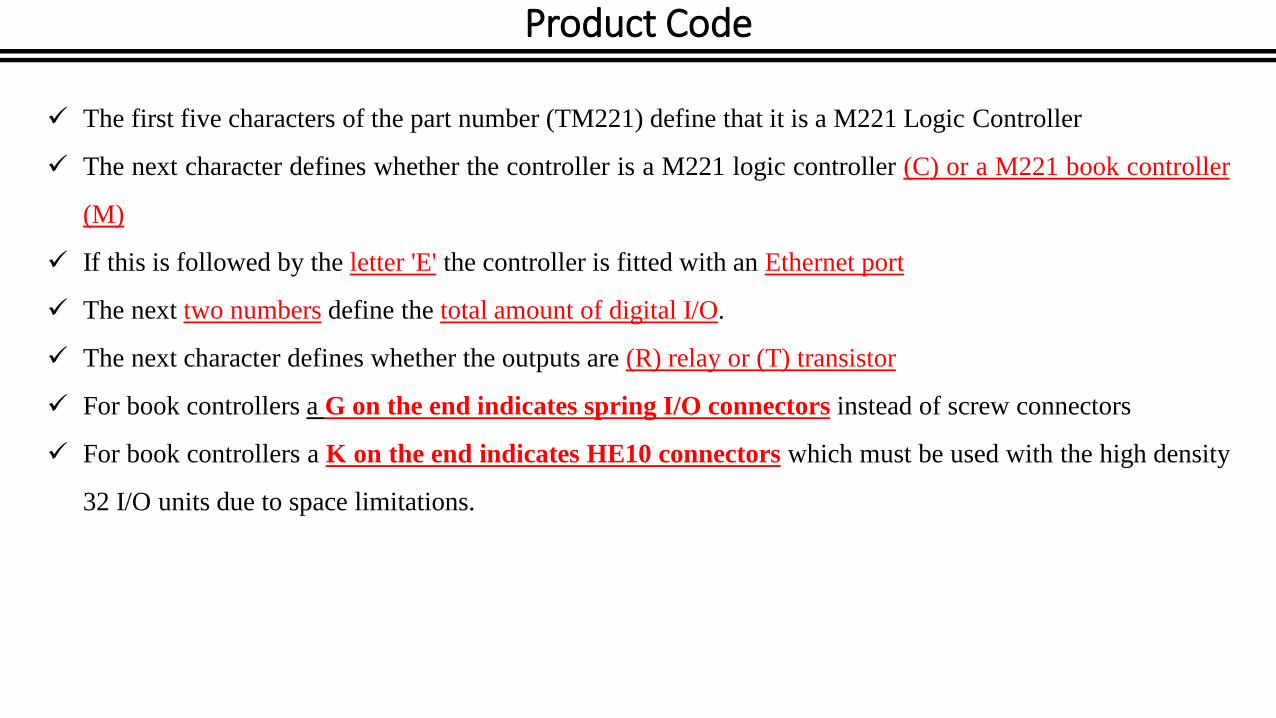
The first five characters of the part number (TM221) define that it is a M221 Logic Controller
The next character defines whether the controller is a M221 logic controller (C) or a M221 book controller
(M)
If this is followed by the letter 'E' the controller is fitted with an Ethernet port
The next two numbers define the total amount of digital I/O.
The next character defines whether the outputs are (R) relay or (T) transistor
For book controllers a G on the end indicates spring I/O connectors instead of screw connectors
For book controllers a K on the end indicates HE10 connectors which must be used with the high density
32 I/O units due to space limitations.

M221 Wiring
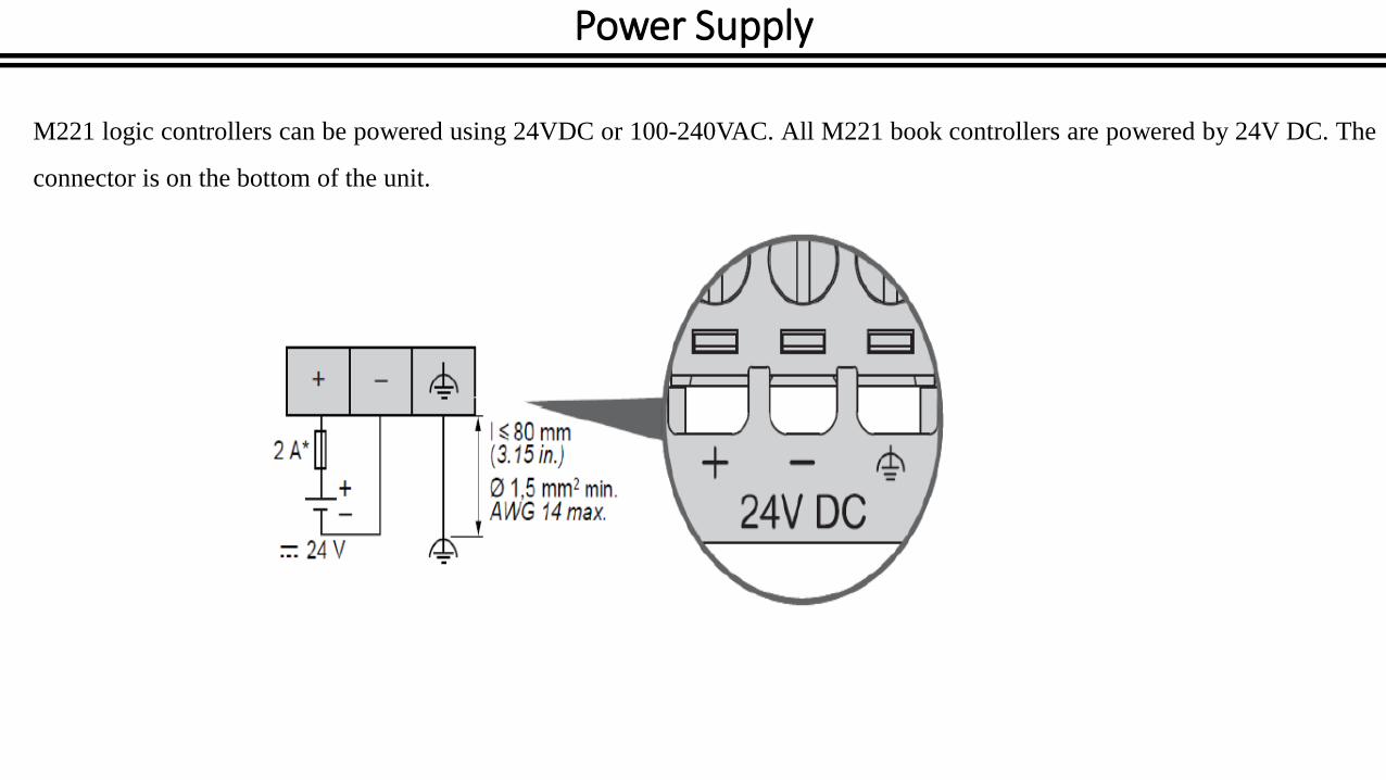
Power Supply
M221 logic controllers can be powered using 24VDC or 100-240VAC. All M221 book controllers are powered by 24V DC. The
connector is on the bottom of the unit.

Analog Inputs
All M221 controllers have two independent 0-10V analog inputs. These are located under the cover at the top left of the unit (it has
the QR code on it). The wiring is as shown.

I/O Connectors
There are three types of connector for the M221 Logic controller I/O. Screw terminals allow each wire to be fitted and a screw will
hold the wire in place. Spring terminals allow the wires to be more easily inserted or extracted.
HE10 connectors are a standard connection for Schneider PLCs and controllers. They allow high density connection so are
ideal for the 32 I/O version of the M221. This connector does require a special cable and different types are available – see the
catalog for details of part numbers. In all cases, the terminal block can be unplugged, allowing the wiring to be easily removed
from the M221.

Input Wiring
The wiring for the 8 and 16 input versions of the M221 Logic Controller are shown below.
The first two inputs are shown shielded as they can be used for high speed pulse inputs so should be protected from noise. If
these are used as normal outputs, they need not be shielded.

Output Wiring
The wiring for the 8 and 16 output versions of the M221 Logic Controller are shown below
The first two outputs are shown shielded as they can be used for high speed pulse outputs so should be protected from noise. If
these are used as normal outputs, they need not be shielded. For the relay output version of the M221, the outputs need not be
shielded as they cannot be used for high speed pulse output.

Expansion

I/O Modules
I/O modules can be added to the M221 controller to expand its capabilities.
There are two types of module that can be added. TM2 modules are existing modules for Twido that can be used and allow the
M221 to be compatible with Twido applications. This makes upgrading from the Twido to M221 simple especially when coupled
with the Twido to M221 application conversion that is part of the SoMachine Basic software. TM3 modules are a new range
specifically designed for the M2xx range of Logic Controllers to take advantage of the extended I/O expansion bus. They offer
new capabilities that are not available to the Twido.
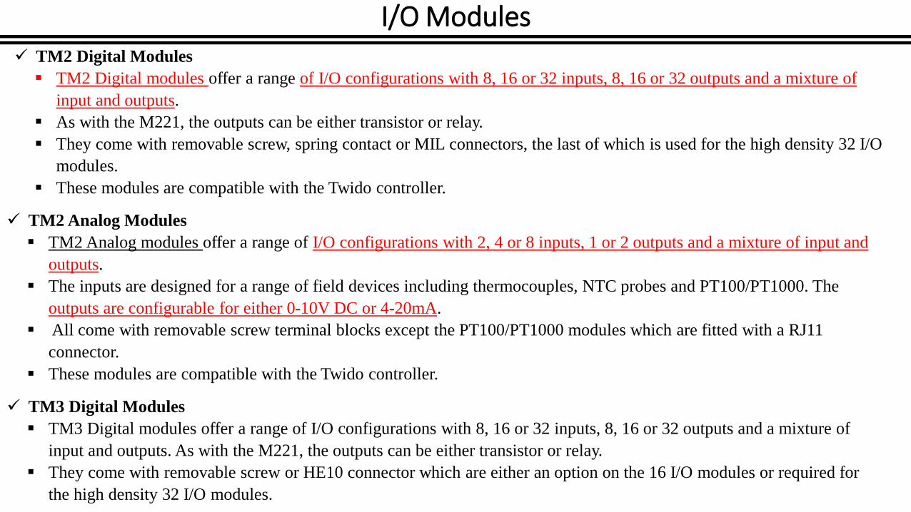
I/O Modules TM2 Digital Modules
TM2 Digital modules offer a range of I/O configurations with 8, 16 or 32 inputs, 8, 16 or 32 outputs and a mixture of
input and outputs.
As with the M221, the outputs can be either transistor or relay.
They come with removable screw, spring contact or MIL connectors, the last of which is used for the high density 32 I/O
modules.
These modules are compatible with the Twido controller.
TM2 Analog Modules
TM2 Analog modules offer a range of I/O configurations with 2, 4 or 8 inputs, 1 or 2 outputs and a mixture of input and
outputs.
The inputs are designed for a range of field devices including thermocouples, NTC probes and PT100/PT1000. The
outputs are configurable for either 0-10V DC or 4-20mA.
All come with removable screw terminal blocks except the PT100/PT1000 modules which are fitted with a RJ11
connector.
These modules are compatible with the Twido controller.
TM3 Digital Modules
TM3 Digital modules offer a range of I/O configurations with 8, 16 or 32 inputs, 8, 16 or 32 outputs and a mixture of
input and outputs. As with the M221, the outputs can be either transistor or relay.
They come with removable screw or HE10 connector which are either an option on the 16 I/O modules or required for
the high density 32 I/O modules.
I/O Modules
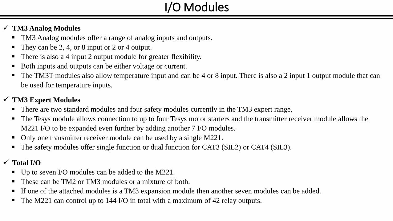
TM3 Analog Modules
TM3 Analog modules offer a range of analog inputs and outputs.
They can be 2, 4, or 8 input or 2 or 4 output.
There is also a 4 input 2 output module for greater flexibility.
Both inputs and outputs can be either voltage or current.
The TM3T modules also allow temperature input and can be 4 or 8 input. There is also a 2 input 1 output module that can
be used for temperature inputs.
TM3 Expert Modules
There are two standard modules and four safety modules currently in the TM3 expert range.
The Tesys module allows connection to up to four Tesys motor starters and the transmitter receiver module allows the
M221 I/O to be expanded even further by adding another 7 I/O modules.
Only one transmitter receiver module can be used by a single M221.
The safety modules offer single function or dual function for CAT3 (SIL2) or CAT4 (SIL3).
Total I/O
Up to seven I/O modules can be added to the M221.
These can be TM2 or TM3 modules or a mixture of both.
If one of the attached modules is a TM3 expansion module then another seven modules can be added.
The M221 can control up to 144 I/O in total with a maximum of 42 relay outputs.
Cartridges
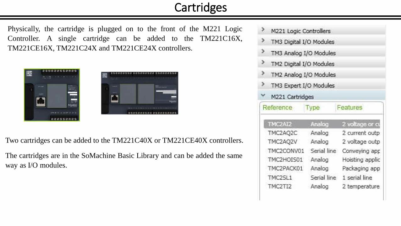
Physically, the cartridge is plugged on to the front of the M221 Logic
Controller. A single cartridge can be added to the TM221C16X,
TM221CE16X, TM221C24X and TM221CE24X controllers.
Two cartridges can be added to the TM221C40X or TM221CE40X controllers.
The cartridges are in the SoMachine Basic Library and can be added the same
way as I/O modules.

Languages
Languages
IEC61131
IEC61131 is the international standard for programming PLCs. Its main purpose is to define standard data types and languages.
There are many data types that will be discussed later, but there are only five programming languages:
Ladder Diagram (LD)
Function Block Diagram (FBD)
Structured Text (ST)
Instruction List (IL)
Sequential Function Chart (SFC)
Of these languages, only Ladder Diagram and Instruction List are currently supported by SoMachine Basic although other
languages are planned for future releases.
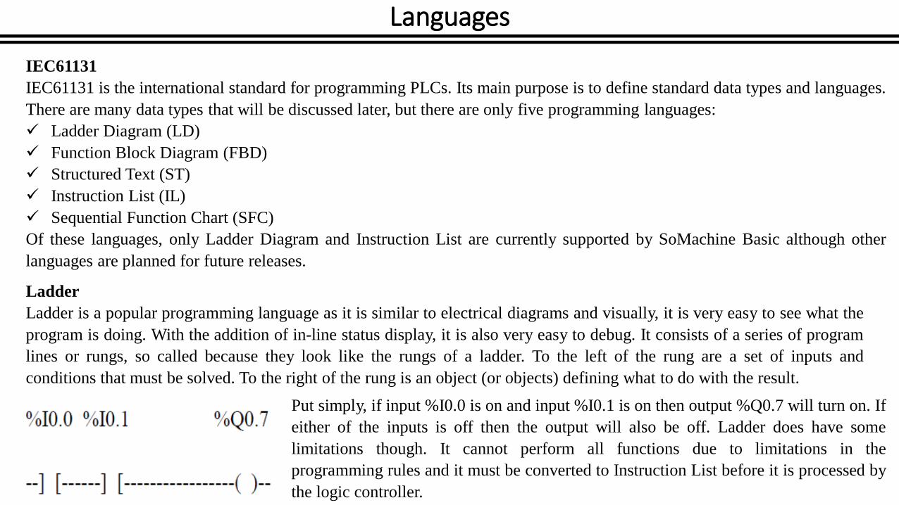
Ladder
Ladder is a popular programming language as it is similar to electrical diagrams and visually, it is very easy to see what the
program is doing. With the addition of in-line status display, it is also very easy to debug. It consists of a series of program
lines or rungs, so called because they look like the rungs of a ladder. To the left of the rung are a set of inputs and
conditions that must be solved. To the right of the rung is an object (or objects) defining what to do with the result.
Put simply, if input %I0.0 is on and input %I0.1 is on then output %Q0.7 will turn on. If
either of the inputs is off then the output will also be off. Ladder does have some
limitations though. It cannot perform all functions due to limitations in the
programming rules and it must be converted to Instruction List before it is processed by
the logic controller.
LanguagesInstruction List
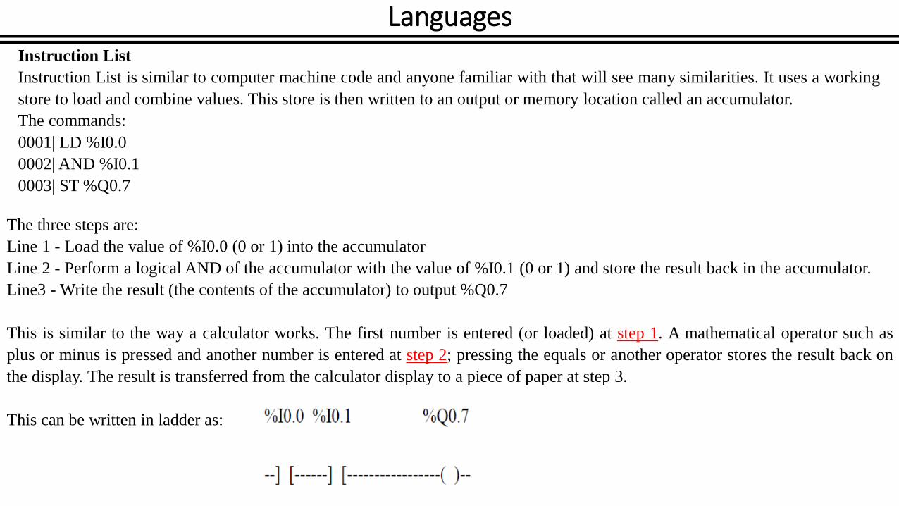
Instruction List is similar to computer machine code and anyone familiar with that will see many similarities. It uses a working
store to load and combine values. This store is then written to an output or memory location called an accumulator.
The commands:
0001| LD %I0.0
0002| AND %I0.1
0003| ST %Q0.7
The three steps are:
Line 1 - Load the value of %I0.0 (0 or 1) into the accumulator
Line 2 - Perform a logical AND of the accumulator with the value of %I0.1 (0 or 1) and store the result back in the accumulator.
Line3 - Write the result (the contents of the accumulator) to output %Q0.7
This is similar to the way a calculator works. The first number is entered (or loaded) at step 1. A mathematical operator such as
plus or minus is pressed and another number is entered at step 2; pressing the equals or another operator stores the result back on
the display. The result is transferred from the calculator display to a piece of paper at step 3.
This can be written in ladder as:

Addressing
Addressing Format
%<Type>[<Identifier>]<Location>
An address must always begin with the % character. This tells the Logic Controller that it is an address, not some other piece
of information. This is followed by one of five letters identifying the type of address:
I The address is a physical input on either the controller or an expansion
module.
K The address is an internal memory location within the controller. The
value is fixed and can NOT be changed by the program.
M The address is an internal memory location within the controller. This
value can be changed by the program.
Q The address is a physical output on either the controller or an expansion
module.
S Internal system locations that are used to perform various functions and
monitor the controller
none The address contains a value that is a single bit having a
value of either 0 or 1.
W The address contains a value that is a word and has a value
between 0 and 65535.
D The address contains a value that is a double word and has
a value between 0 and 4294967295.
F The address contains a value that is in floating point format
and has a value between 0 and 65535.

Addressing I/O Objects
Object Type Syntax Example Description
Memory bits %Mi %M25 Internal memory bit 25.
Memory words %MWi %MW15 Internal memory word 15.
Memory double words %MDi %MD16 Internal memory double word 16.
Memory floating points %MFi %MF17 Internal memory floating point 17.
Constant words %KWi %KW26 Constant word 26.
Constant double words %KDi %KD27 Internal constant double word 27.
Constant floating points %KFi %KF28 Internal constant floating point 28.
Memory objects

Object Type Syntax Example DescriptionSystem bits %Si %S8 System bit 8. System words %SWi %SW30 System word 30.
System objects
Object Type Syntax Example Description
Digital inputs %Iy.z %I0,5 Digital input 5 on the controller (embedded I/O).
Digital outputs %Qy.z %Q3,4 Digital output 4 on the expansion module at address 3 (expansion module I/O).
Analog inputs %IWy.z %IW0,1 Analog input 1 on the controller (embedded I/O).
Fast counters %FCi %FC2 Fast counter 2 on the controller.
High speed counters %HSCi %HSC1 High speed counter 1 on the controller.
Pulse %PLSi %PLS0 Pulse output 0 on the controller.
Pulse width modulation %PWMi
%PWM1 Pulse width modulation output 1 on the controller.
I/O objects
Addressing I/O Objects

Object Type Syntax Example DescriptionTimers %TMi %TM5 Timer instance 5. Counters %Ci %C2 Counter instance 2. Message %MSGi %MSG1 Program compilation status message 1. LIFO/FIFO registers %Ri %R3 FIFO/LIFO registers instance 3. Drum controllers %DRi %DR6 Drum controller 6 on the controller. Shift bit registers %SBRi %SBR5 Shift bit register 5 on the controller. Step counters %SCi %SC5 Step counter 5 on the controller. Schedule blocks SCH i SCH 3 Schedule block 3 on the controller. PID control PID i PID 7 PID feedback object 7 on the controller.
Software objects
Addressing I/O Objects

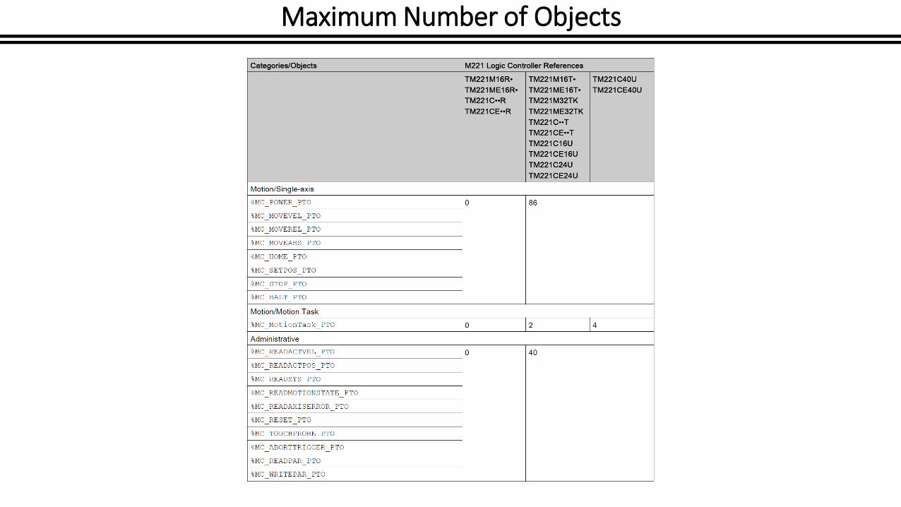
Maximum Number of Objects

Maximum Number of Objects

Maximum Number of Objects
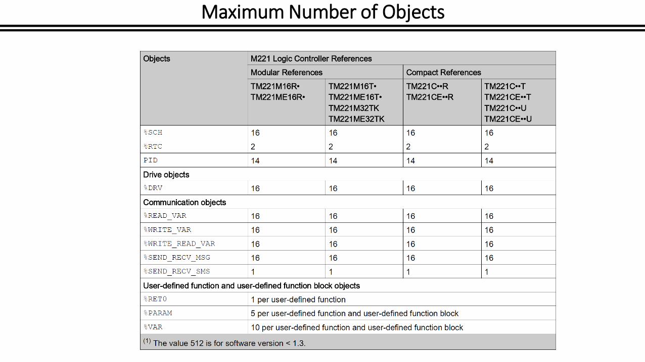
Maximum Number of Objects
Maximum Number of Objects

Data Types
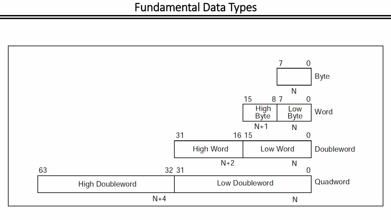
Fundamental Data Types
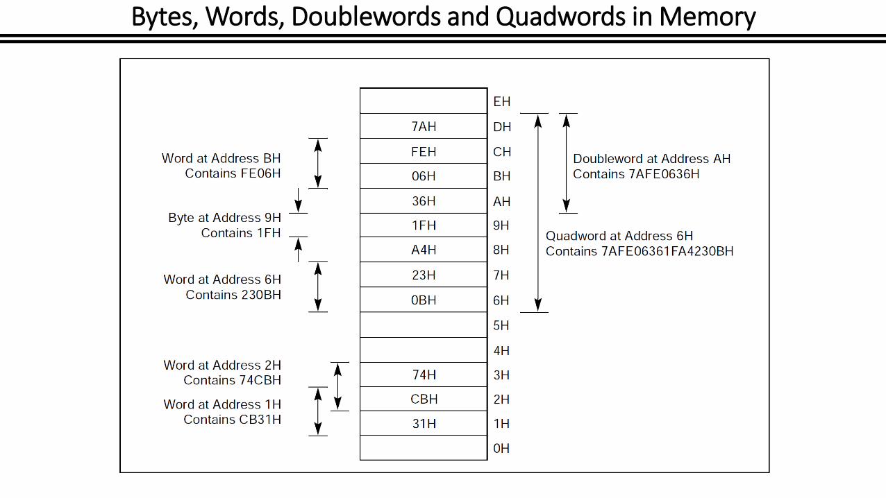
Bytes, Words, Doublewords and Quadwords in Memory
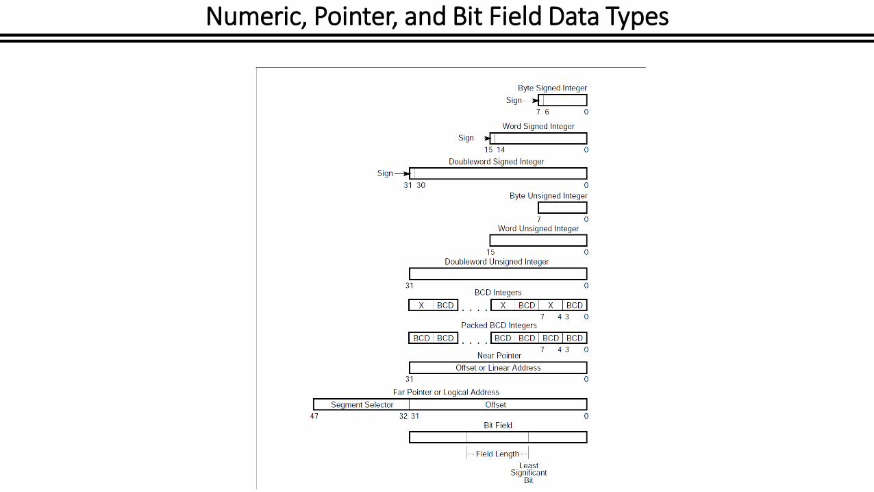
Numeric, Pointer, and Bit Field Data Types

Meanings of Identification Letters (Courtesy of the Instrument Society of America)

Flow control system
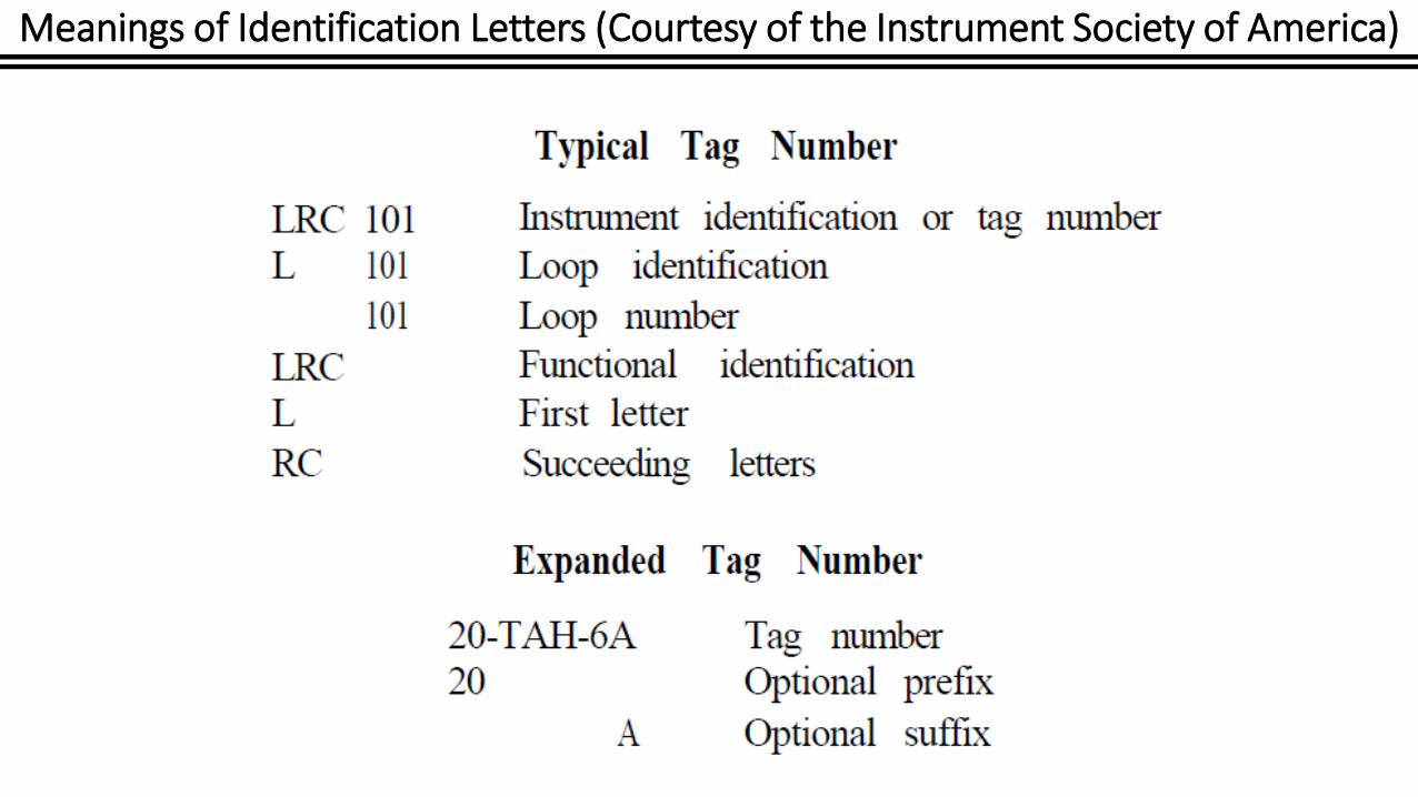
Meanings of Identification Letters (Courtesy of the Instrument Society of America)
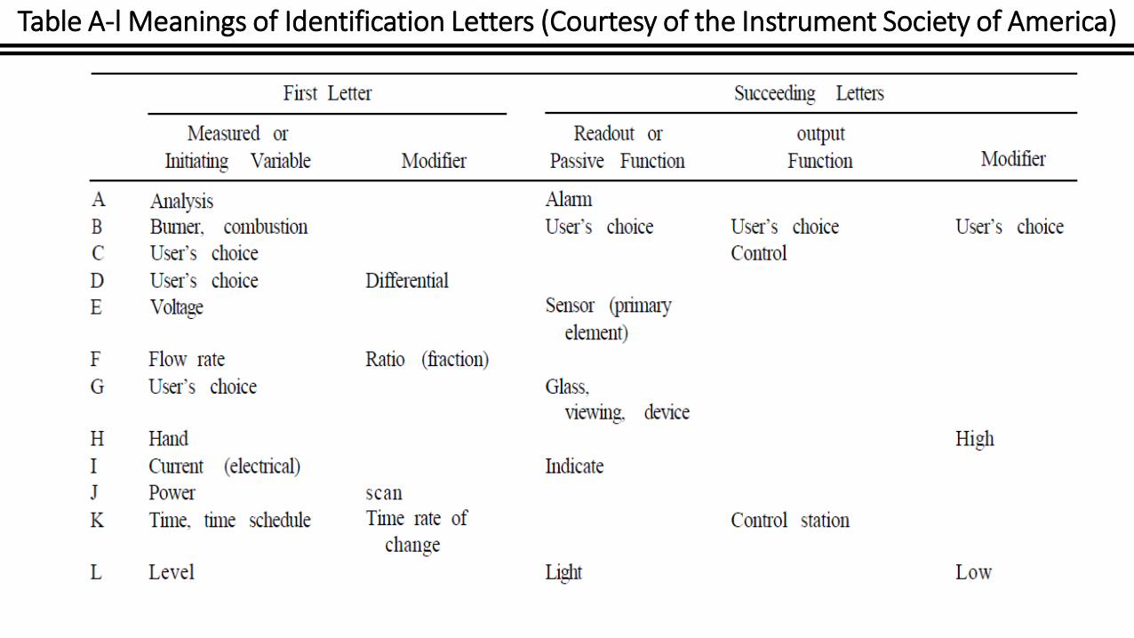
Table A-l Meanings of Identification Letters (Courtesy of the Instrument Society of America)
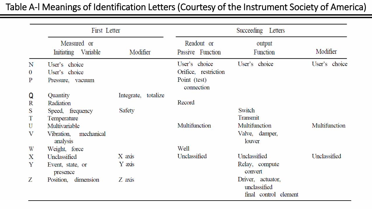
Table A-l Meanings of Identification Letters (Courtesy of the Instrument Society of America)

Table A-l Meanings of Identification Letters (Courtesy of the Instrument Society of America)

Table A-l Meanings of Identification Letters (Courtesy of the Instrument Society of America)
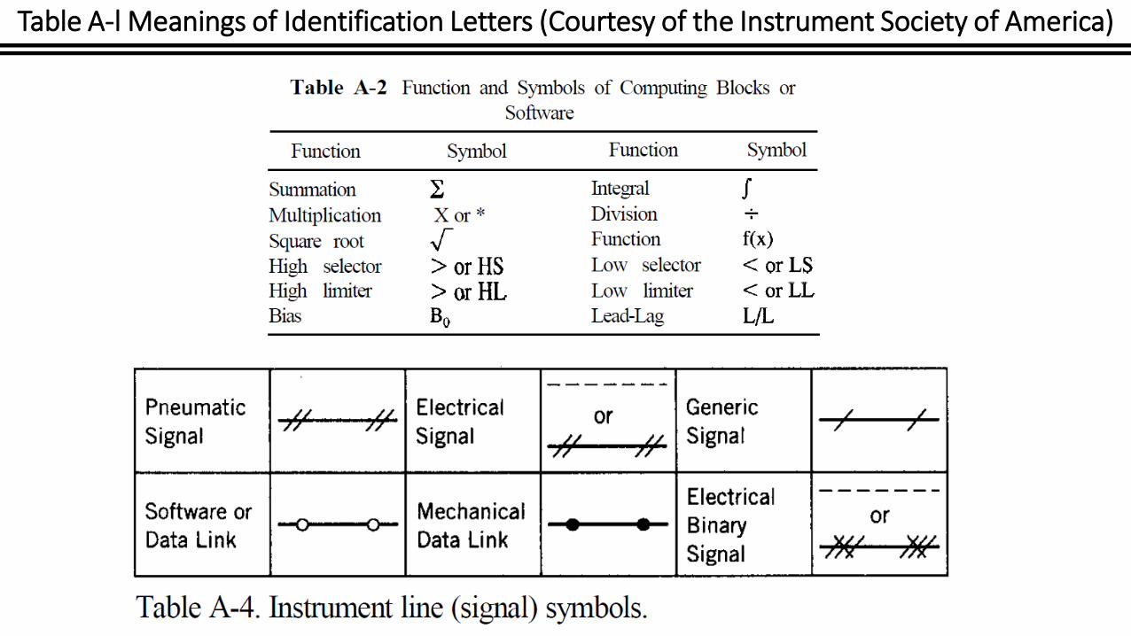
Table A-l Meanings of Identification Letters (Courtesy of the Instrument Society of America)

General instrument symbols.

General instrument symbols

Flow control system
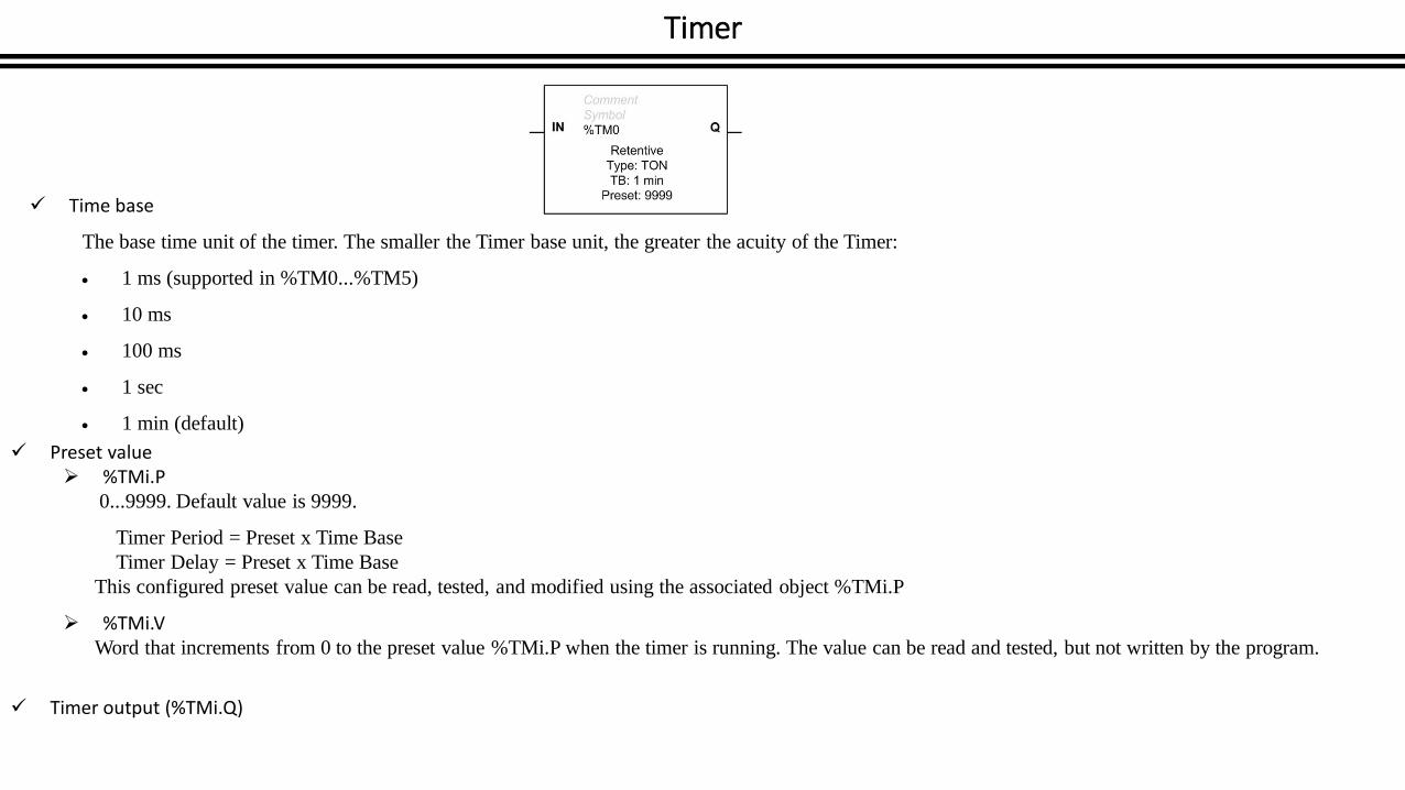
Timer
Time base
The base time unit of the timer. The smaller the Timer base unit, the greater the acuity of the Timer:
1 ms (supported in %TM0...%TM5)
10 ms
100 ms
1 sec
1 min (default)
Preset value %TMi.P
0...9999. Default value is 9999.
Timer Period = Preset x Time Base
Timer Delay = Preset x Time Base
This configured preset value can be read, tested, and modified using the associated object %TMi.P
%TMi.VWord that increments from 0 to the preset value %TMi.P when the timer is running. The value can be read and tested, but not written by the program.
Timer output (%TMi.Q)
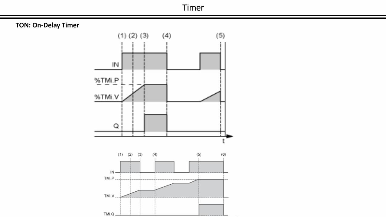
Timer
TON: On-Delay Timer

Timer
TOF: Off-Delay Timer

Timer
TP: Pulse Timer

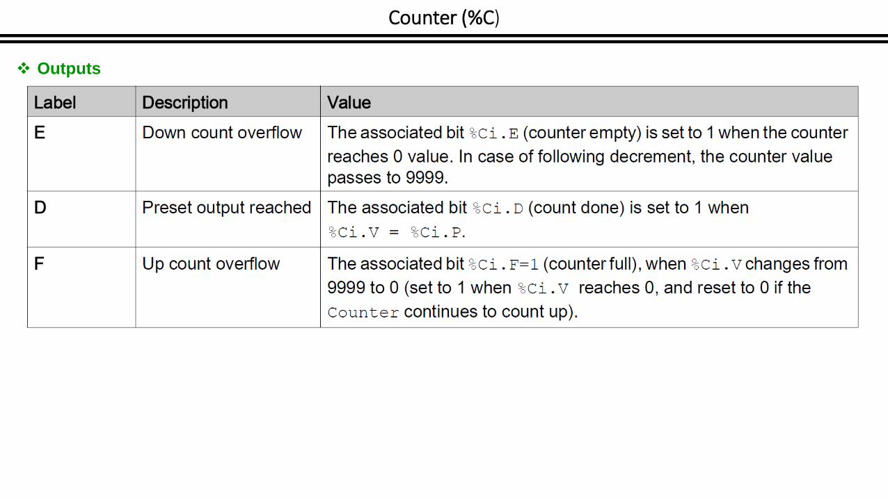
Counter (%C)
Inputs
Counter (%C)
Outputs
Counter (%C)
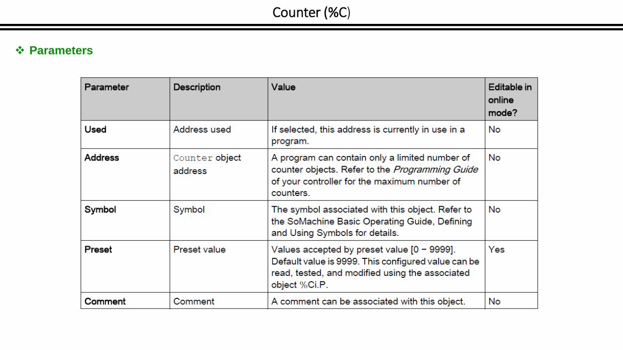
Parameters

Counter (%C)
Objects