Embed Size (px)
Citation preview
© 2011-2012 Calypso Ventures, Inc.
The MachStdMill project: Customizing CNC Control Software. Part 2
By David Bagby, Calypso Ventures, Inc.
In the 1st article in this series, we looked at work flow driven screen set design, how it mapped to the common steps involved in making a part, and how context can be used to dynamically present information. In this article, we’ll show what can happen when the control software is enhanced to automate common personal CNC operator tasks. Automating setup operations: We start with a look at examples of extended functionality which make part setup operations easier. In part 1, we used a touch off operation to locate the part in physical space and thereby position the part to be cut out of the stock. Touch off techniques have some disadvantages:
1) They inherently require multiple manual operations to locate the origin (one touch for each face of the stock).
2) They tend to encourage operators to be within the work envelope of the machine while jogging movements are performed (machinists often hold a piece of paper between the tool and the part to tell when the tool is touching). It’s safer to be outside the work area anytime there is machine movement.
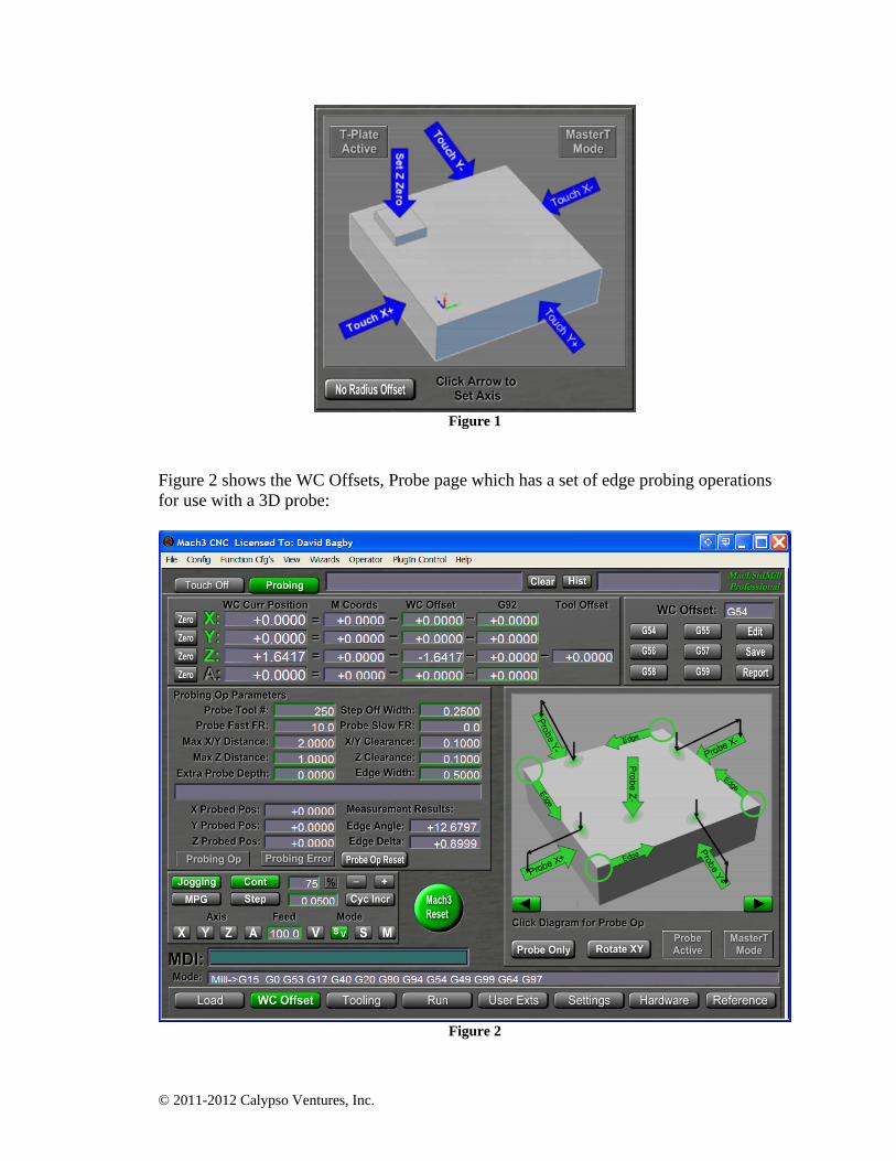
Wouldn’t it be nice to be able to say: “Find the corner of the stock and put Zero there”? That can be done using a tool known as a “probe” and some smart software enhancements. Probes are devices designed to be used with a G31 preparatory command. G31 specifies movement to a given position, but will stop movement if the probe encounters an object. When an object is found, a hardware signal is sent to the control. The signal enables the control to know the coordinate location where the probe was triggered. With probe device support, many operations become easier1. MSM utilizes the basic G31 functionality to implement composite probing operations which an operator can use for stock setup operations. Probing operations are integrated with the user interface (UI) and are designed to take the manual effort out of job setup. In part one of this series we saw this set of touch operations on the WC Offsets, Touch Off page (see figure 1):
1 Probing operations do require the presence of a probe tool. MSM supports three types of “probe input devices” (a mobile touch plate, a fixed touch plate at the tool change position and a 3D probe tool). All three may be present on a single machine.
© 2011-2012 Calypso Ventures, Inc.
Figure 1
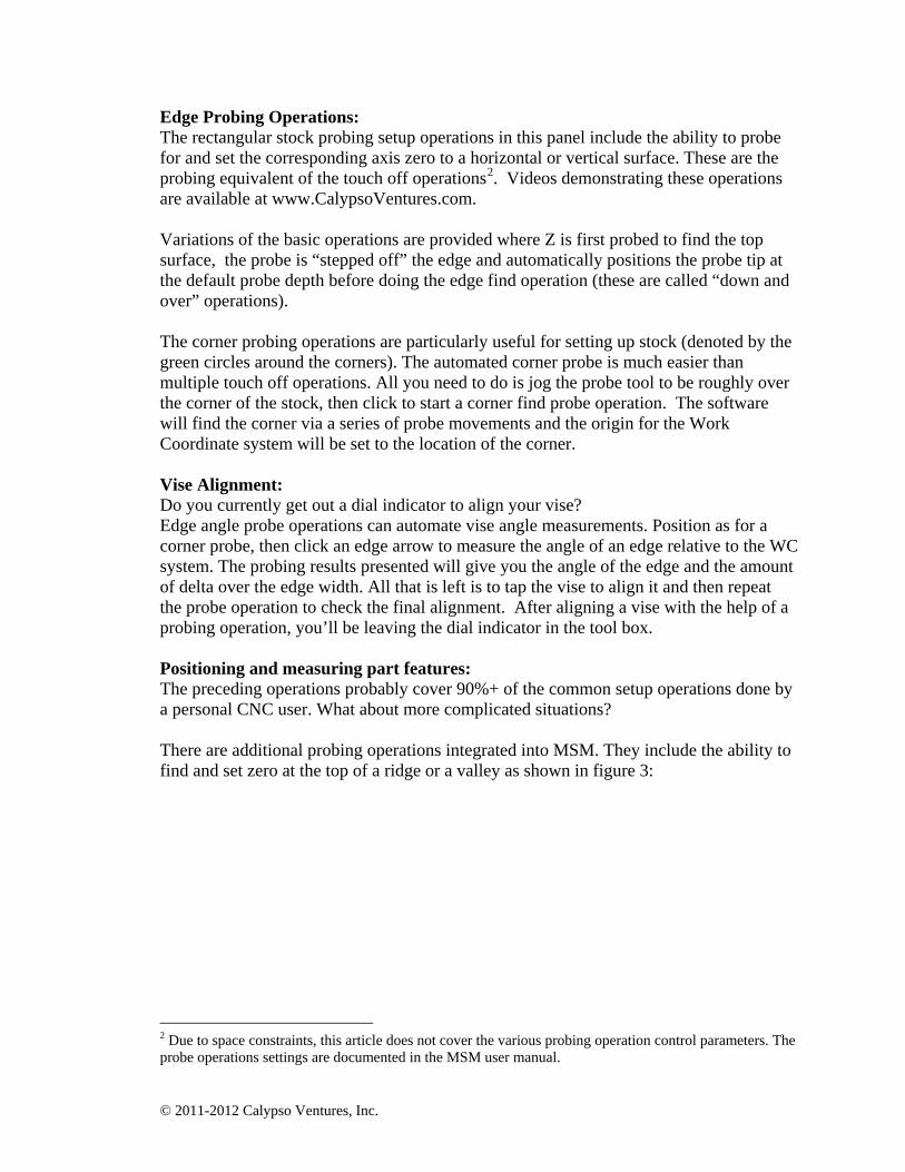
Figure 2 shows the WC Offsets, Probe page which has a set of edge probing operations for use with a 3D probe:
Figure 2
© 2011-2012 Calypso Ventures, Inc.
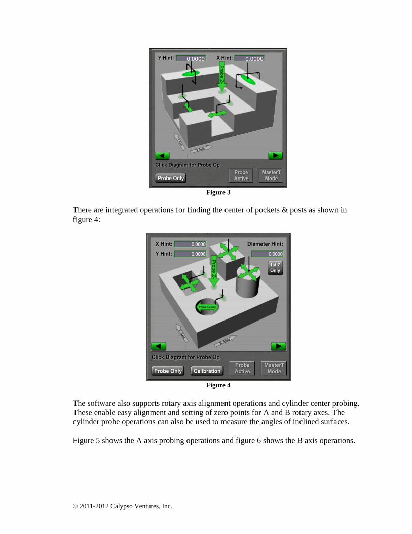
Edge Probing Operations: The rectangular stock probing setup operations in this panel include the ability to probe for and set the corresponding axis zero to a horizontal or vertical surface. These are the probing equivalent of the touch off operations2. Videos demonstrating these operations are available at www.CalypsoVentures.com. Variations of the basic operations are provided where Z is first probed to find the top surface, the probe is “stepped off” the edge and automatically positions the probe tip at the default probe depth before doing the edge find operation (these are called “down and over” operations). The corner probing operations are particularly useful for setting up stock (denoted by the green circles around the corners). The automated corner probe is much easier than multiple touch off operations. All you need to do is jog the probe tool to be roughly over the corner of the stock, then click to start a corner find probe operation. The software will find the corner via a series of probe movements and the origin for the Work Coordinate system will be set to the location of the corner. Vise Alignment: Do you currently get out a dial indicator to align your vise? Edge angle probe operations can automate vise angle measurements. Position as for a corner probe, then click an edge arrow to measure the angle of an edge relative to the WC system. The probing results presented will give you the angle of the edge and the amount of delta over the edge width. All that is left is to tap the vise to align it and then repeat the probe operation to check the final alignment. After aligning a vise with the help of a probing operation, you’ll be leaving the dial indicator in the tool box. Positioning and measuring part features: The preceding operations probably cover 90%+ of the common setup operations done by a personal CNC user. What about more complicated situations? There are additional probing operations integrated into MSM. They include the ability to find and set zero at the top of a ridge or a valley as shown in figure 3:
2 Due to space constraints, this article does not cover the various probing operation control parameters. The probe operations settings are documented in the MSM user manual.
© 2011-2012 Calypso Ventures, Inc.
Figure 3
There are integrated operations for finding the center of pockets & posts as shown in figure 4:
Figure 4
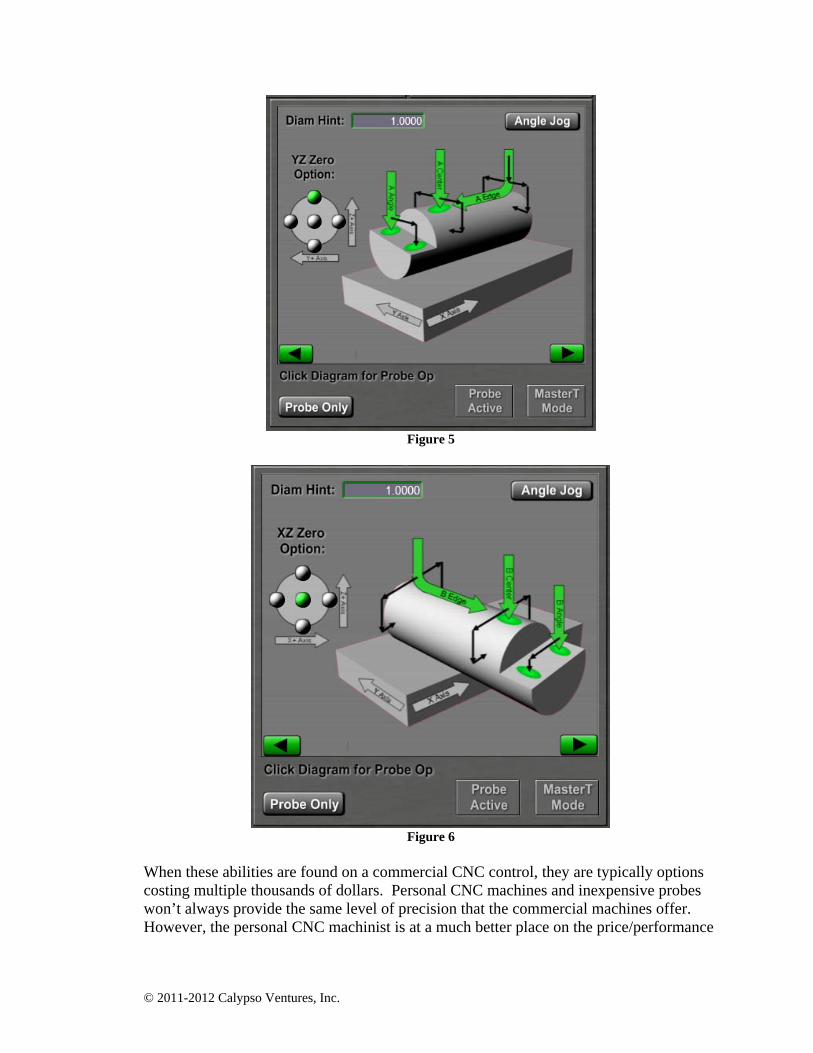
The software also supports rotary axis alignment operations and cylinder center probing. These enable easy alignment and setting of zero points for A and B rotary axes. The cylinder probe operations can also be used to measure the angles of inclined surfaces. Figure 5 shows the A axis probing operations and figure 6 shows the B axis operations.
© 2011-2012 Calypso Ventures, Inc.
Figure 5
Figure 6
When these abilities are found on a commercial CNC control, they are typically options costing multiple thousands of dollars. Personal CNC machines and inexpensive probes won’t always provide the same level of precision that the commercial machines offer. However, the personal CNC machinist is at a much better place on the price/performance
© 2011-2012 Calypso Ventures, Inc.
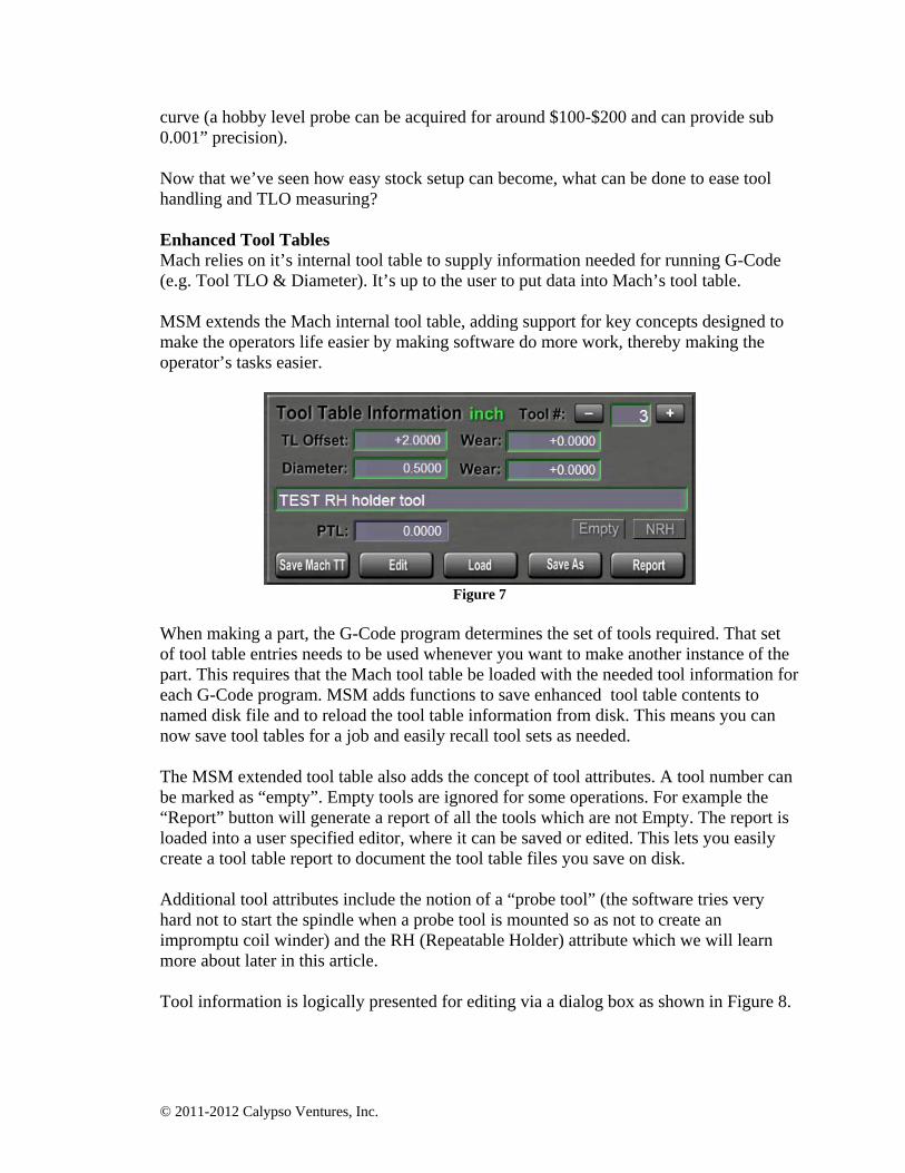
curve (a hobby level probe can be acquired for around $100-$200 and can provide sub 0.001” precision). Now that we’ve seen how easy stock setup can become, what can be done to ease tool handling and TLO measuring? Enhanced Tool Tables Mach relies on it’s internal tool table to supply information needed for running G-Code (e.g. Tool TLO & Diameter). It’s up to the user to put data into Mach’s tool table. MSM extends the Mach internal tool table, adding support for key concepts designed to make the operators life easier by making software do more work, thereby making the operator’s tasks easier.
Figure 7
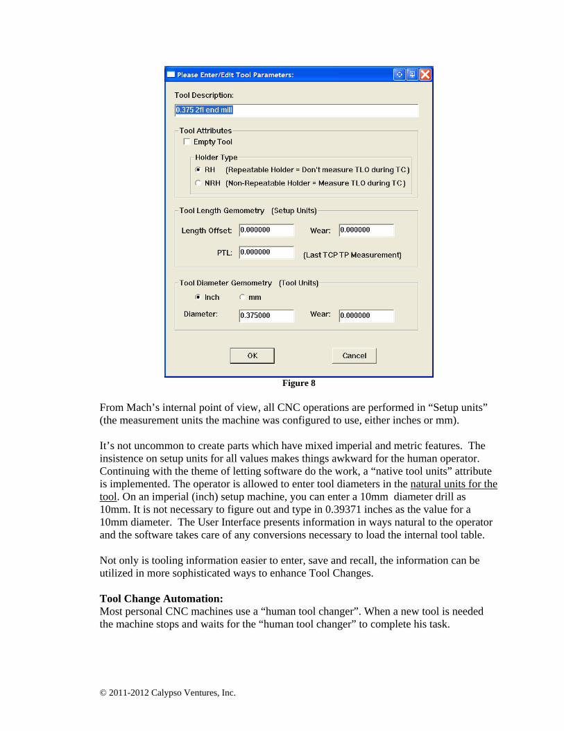
When making a part, the G-Code program determines the set of tools required. That set of tool table entries needs to be used whenever you want to make another instance of the part. This requires that the Mach tool table be loaded with the needed tool information for each G-Code program. MSM adds functions to save enhanced tool table contents to named disk file and to reload the tool table information from disk. This means you can now save tool tables for a job and easily recall tool sets as needed. The MSM extended tool table also adds the concept of tool attributes. A tool number can be marked as “empty”. Empty tools are ignored for some operations. For example the “Report” button will generate a report of all the tools which are not Empty. The report is loaded into a user specified editor, where it can be saved or edited. This lets you easily create a tool table report to document the tool table files you save on disk. Additional tool attributes include the notion of a “probe tool” (the software tries very hard not to start the spindle when a probe tool is mounted so as not to create an impromptu coil winder) and the RH (Repeatable Holder) attribute which we will learn more about later in this article. Tool information is logically presented for editing via a dialog box as shown in Figure 8.
© 2011-2012 Calypso Ventures, Inc.
Figure 8
From Mach’s internal point of view, all CNC operations are performed in “Setup units” (the measurement units the machine was configured to use, either inches or mm). It’s not uncommon to create parts which have mixed imperial and metric features. The insistence on setup units for all values makes things awkward for the human operator. Continuing with the theme of letting software do the work, a “native tool units” attribute is implemented. The operator is allowed to enter tool diameters in the natural units for the tool. On an imperial (inch) setup machine, you can enter a 10mm diameter drill as 10mm. It is not necessary to figure out and type in 0.39371 inches as the value for a 10mm diameter. The User Interface presents information in ways natural to the operator and the software takes care of any conversions necessary to load the internal tool table. Not only is tooling information easier to enter, save and recall, the information can be utilized in more sophisticated ways to enhance Tool Changes. Tool Change Automation: Most personal CNC machines use a “human tool changer”. When a new tool is needed the machine stops and waits for the “human tool changer” to complete his task.
© 2011-2012 Calypso Ventures, Inc.
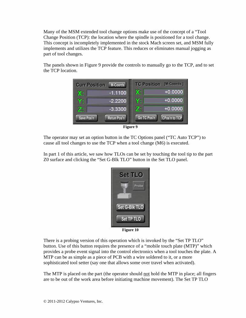
Many of the MSM extended tool change options make use of the concept of a “Tool Change Position (TCP): the location where the spindle is positioned for a tool change. This concept is incompletely implemented in the stock Mach screen set, and MSM fully implements and utilizes the TCP feature. This reduces or eliminates manual jogging as part of tool changes. The panels shown in Figure 9 provide the controls to manually go to the TCP, and to set the TCP location.
Figure 9
The operator may set an option button in the TC Options panel (“TC Auto TCP”) to cause all tool changes to use the TCP when a tool change (M6) is executed. In part 1 of this article, we saw how TLOs can be set by touching the tool tip to the part Z0 surface and clicking the “Set G-Blk TLO” button in the Set TLO panel.
Figure 10
There is a probing version of this operation which is invoked by the “Set TP TLO” button. Use of this button requires the presence of a “mobile touch plate (MTP)” which provides a probe event signal into the control electronics when a tool touches the plate. A MTP can be as simple as a piece of PCB with a wire soldered to it, or a more sophisticated tool setter (say one that allows some over travel when activated). The MTP is placed on the part (the operator should not hold the MTP in place; all fingers are to be out of the work area before initiating machine movement). The Set TP TLO
© 2011-2012 Calypso Ventures, Inc.
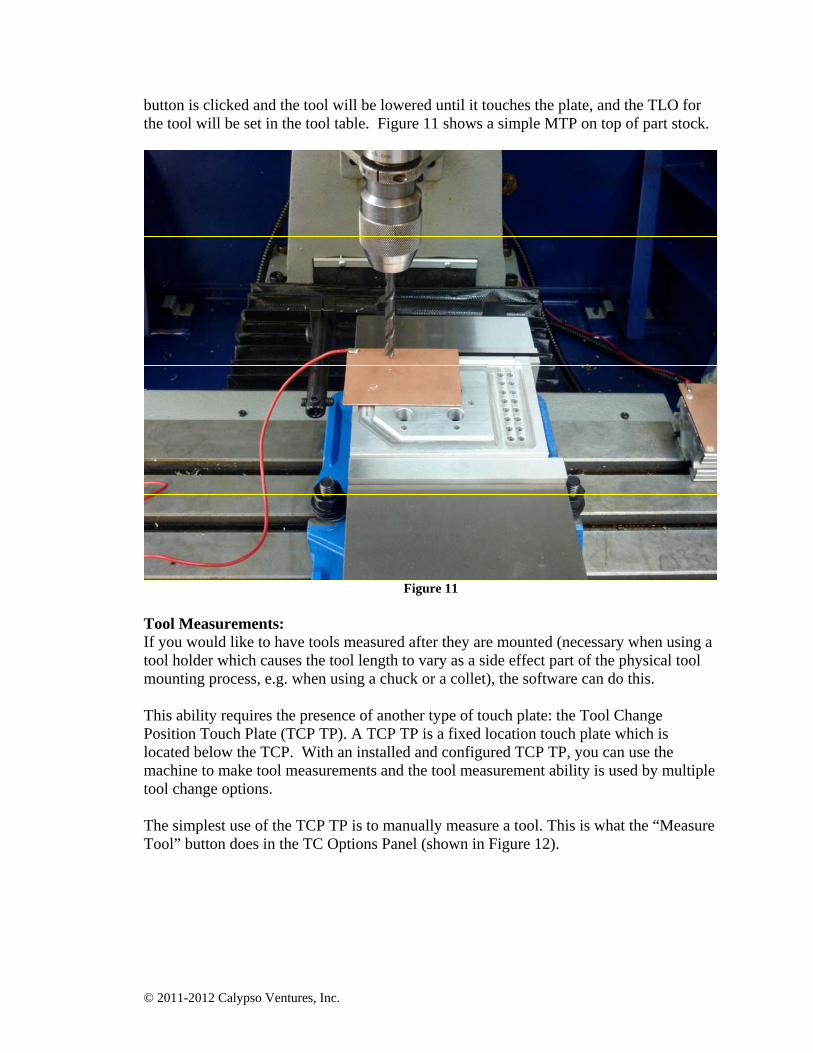
button is clicked and the tool will be lowered until it touches the plate, and the TLO for the tool will be set in the tool table. Figure 11 shows a simple MTP on top of part stock.
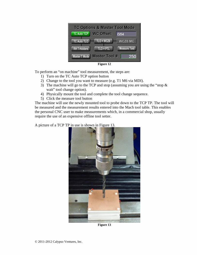
Figure 11 Tool Measurements: If you would like to have tools measured after they are mounted (necessary when using a tool holder which causes the tool length to vary as a side effect part of the physical tool mounting process, e.g. when using a chuck or a collet), the software can do this. This ability requires the presence of another type of touch plate: the Tool Change Position Touch Plate (TCP TP). A TCP TP is a fixed location touch plate which is located below the TCP. With an installed and configured TCP TP, you can use the machine to make tool measurements and the tool measurement ability is used by multiple tool change options. The simplest use of the TCP TP is to manually measure a tool. This is what the “Measure Tool” button does in the TC Options Panel (shown in Figure 12).
© 2011-2012 Calypso Ventures, Inc.
Figure 12
To perform an “on machine” tool measurement, the steps are:
1) Turn on the TC Auto TCP option button 2) Change to the tool you want to measure (e.g. T1 M6 via MDI). 3) The machine will go to the TCP and stop (assuming you are using the “stop &
wait” tool change option). 4) Physically mount the tool and complete the tool change sequence. 5) Click the measure tool button
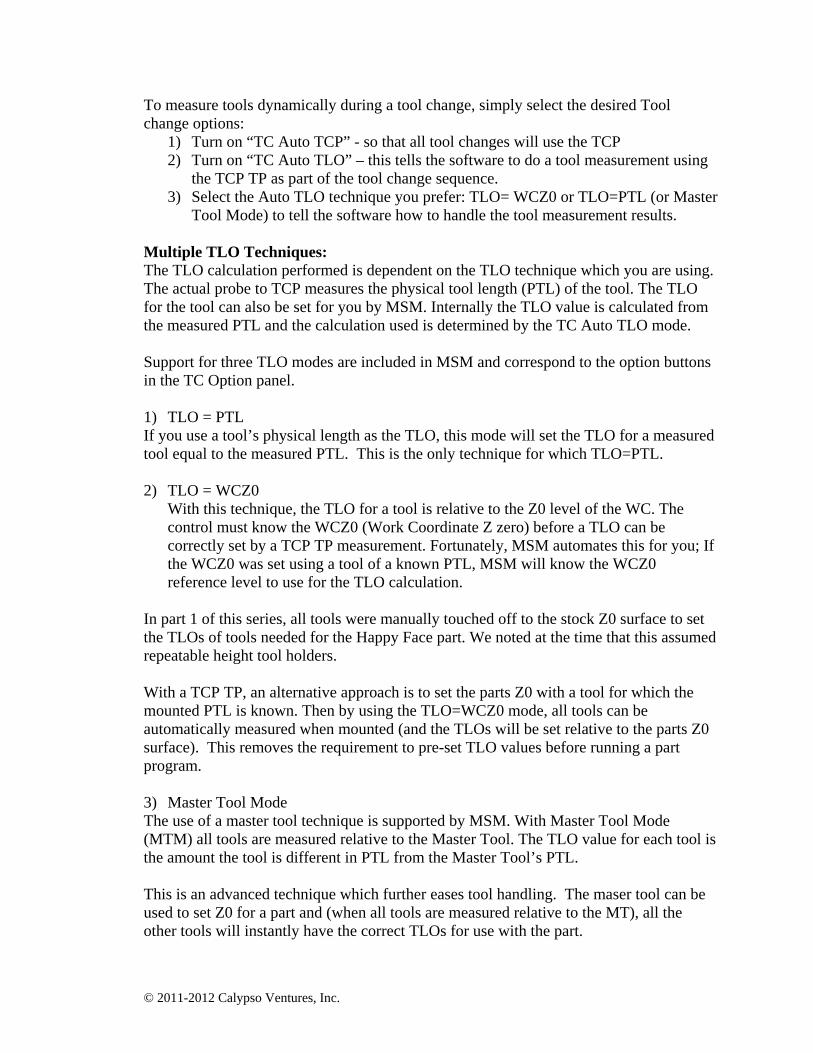
The machine will use the newly mounted tool to probe down to the TCP TP. The tool will be measured and the measurement results entered into the Mach tool table. This enables the personal CNC user to make measurements which, in a commercial shop, usually require the use of an expensive offline tool setter. A picture of a TCP TP in use is shown in Figure 13.
Figure 13
© 2011-2012 Calypso Ventures, Inc.
To measure tools dynamically during a tool change, simply select the desired Tool change options:
1) Turn on “TC Auto TCP” - so that all tool changes will use the TCP 2) Turn on “TC Auto TLO” – this tells the software to do a tool measurement using
the TCP TP as part of the tool change sequence. 3) Select the Auto TLO technique you prefer: TLO= WCZ0 or TLO=PTL (or Master
Tool Mode) to tell the software how to handle the tool measurement results. Multiple TLO Techniques: The TLO calculation performed is dependent on the TLO technique which you are using. The actual probe to TCP measures the physical tool length (PTL) of the tool. The TLO for the tool can also be set for you by MSM. Internally the TLO value is calculated from the measured PTL and the calculation used is determined by the TC Auto TLO mode. Support for three TLO modes are included in MSM and correspond to the option buttons in the TC Option panel. 1) TLO = PTL If you use a tool’s physical length as the TLO, this mode will set the TLO for a measured tool equal to the measured PTL. This is the only technique for which TLO=PTL. 2) TLO = WCZ0
With this technique, the TLO for a tool is relative to the Z0 level of the WC. The control must know the WCZ0 (Work Coordinate Z zero) before a TLO can be correctly set by a TCP TP measurement. Fortunately, MSM automates this for you; If the WCZ0 was set using a tool of a known PTL, MSM will know the WCZ0 reference level to use for the TLO calculation.
In part 1 of this series, all tools were manually touched off to the stock Z0 surface to set the TLOs of tools needed for the Happy Face part. We noted at the time that this assumed repeatable height tool holders.
With a TCP TP, an alternative approach is to set the parts Z0 with a tool for which the mounted PTL is known. Then by using the TLO=WCZ0 mode, all tools can be automatically measured when mounted (and the TLOs will be set relative to the parts Z0 surface). This removes the requirement to pre-set TLO values before running a part program.
3) Master Tool Mode The use of a master tool technique is supported by MSM. With Master Tool Mode (MTM) all tools are measured relative to the Master Tool. The TLO value for each tool is the amount the tool is different in PTL from the Master Tool’s PTL. This is an advanced technique which further eases tool handling. The maser tool can be used to set Z0 for a part and (when all tools are measured relative to the MT), all the other tools will instantly have the correct TLOs for use with the part.
© 2011-2012 Calypso Ventures, Inc.
Using the probe tool as the master tool can be quite convenient. With this combination (MTM “On” and MT=Probe tool), whenever the probe tool is used to set the stock origin, the TLOs for all the tools are also now set. This reduces the entire series of “set stock origin and set all the tool TLO steps” to just a single corner probe operation.
Mixed Tooling Usage: Finally let’s consider the “RH T-Holders” TC Option button. Commercial CNC machine shops only use tool holders which are inherently “repeatable height”. Their entire work flow and TLO techniques are predicated on this assumption of RH holder use. Spindle tapers in commercial CNC machines are designed to achieve repeatable height tool mounting. Personal CNC machinists are usually not so blessed. Our machines are often R-8 spindle tapers and we often use tool holders that can’t provide repeatable tool lengths. In fact, RTH holders are more the norm than the exception. As personal CNC users learn the ropes and expand their tooling collection, they often start investing in RH holders of some type. However, it’s a rare personal CNC machinist that can afford to buy a complete set of RH holder and use only those holders. The RH/NRH (“Repeatable Height / “Non-repeatable Height” ) tool attribute allows the easy use of both types of tool holders. The personal CNC machinist may use any mixture of RH and NRH holders. Simply mark the tool as RH/NRH in the extended tool table. The “RH T-Holders” tool change option button tells MSM whether to measure RH holders or not during a tool change. When this option is On, NRH tools will be measured and RH tools will not be measured (the TLO values in the tool table for the RH tool will be used). This can save tool change time for RH tools. This second article has shown that Mach’s customization facilities enable a high level of feature enhancements. Enhancements can be used to make major changes in how the user interacts with the CNC control, and can also provide enhanced system features to make both common job setup tasks and tool handling much easier for the CNC operator. In the final part of the series, we’ll look under the hood and learn how the 3.43.xx Mach scripting extensions made these features possible. We’ll also look at some common scripting habits that are no longer needed now that the script extensions are available. Correspondence regarding this article may be emailed to the author via [email protected]. The enhanced features described in this article are available as part of the MachStdMill Professional Edition available from www.Calypsoventures.com