Embed Size (px)
Citation preview
Uptime is a registered trademark of NetexpressUSA, Inc. The following article is used with permission from Uptime Magazine. Copyright© 2006 by NetexpressUSA, Inc. All rights reserved.
uptimet h e m a g a z i n e f o r Pd M & C B M p r o f e s s i o n a l s
feb
2006
www.uptimemagazine.com
Motors: The Past is Present
Windows to the IR World
Hunting in the Haystack
Alignment: Fountain of Youth for Bearings
Acceleration Enveloping, sometimes referred to as Demodulation, Shock Pulse Spectrum, or Spike Energy Spec-trum, is a highly useful signal processing technique primarily used for the detection of rolling element bearing prob-lems in the early stages of damage. Often acceleration enveloping is overlooked as a key analysis tool because little is known about the measurement and how it is derived. The purpose of this article is to explain how Acceleration Enveloping is derived and to show its usefulness in the early detection of rolling element bearing faults.
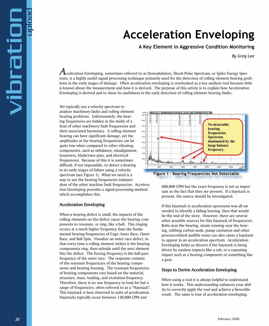
We typically use a velocity spectrum to analyze machinery faults and rolling element bearing problems. Unfortunately, the bear-ing frequencies are hidden in the midst of a host of other machinery fault frequencies and their associated harmonics. A rolling element bearing can have significant damage, yet the amplitudes at the bearing frequencies can be quite low when compared to other vibrating components, such as imbalance, misalignment, looseness, blade/vane pass, and electrical frequencies. Because of this it is sometimes difficult, if not impossible, to detect a bearing in its early stages of failure using a velocity spectrum (see Figure 1). What we need is a way to see the bearing frequencies indepen-dent of the other machine fault frequencies. Accelera-tion Enveloping provides a signal processing method which accomplishes this.
Acceleration Enveloping
When a bearing defect is small, the impacts of the rolling elements on the defect cause the bearing com-ponents to resonate, or ring, like a bell. This ringing occurs at a much higher frequency than the funda-mental bearing frequencies of Cage, Inner Race, Outer Race, and Ball Spin. Visualize an outer race defect, in that every time a rolling element strikes it the bearing components ring, then subside until the next element hits the defect. The forcing frequency is the ball pass frequency of the outer race. The response consists of the resonant frequencies of the bearing compo-nents and bearing housing. The resonant frequencies of bearing components vary based on the material, structure, mass, loading, and excitation frequency. Therefore, there is no one frequency to look for but a range of frequencies, often referred to as a “Haystack”. This haystack is best observed in units of acceleration. Haystacks typically occur between 120,000 CPM and
600,000 CPM but the exact frequency is not as impor-tant as the fact that they are present. If a haystack is present, the source should be investigated.
If this haystack in acceleration spectrums was all we needed to identify a failing bearing, then that would be the end of the story. However, there are several other possible sources for this haystack of frequencies. Rubs near the bearing, steam running near the bear-ing, rubbing carbon seals, pump cavitation and other process-related audible noise can also cause a haystack to appear in an acceleration spectrum. Acceleration Enveloping helps us discern if the haystack is being driven by random impacts like a rub, or a repeating impact such as a bearing component or something like a gear.
Steps to Derive Acceleration Enveloping
When using a tool it is always helpful to understand how it works. This understanding enhances your abil-ity to correctly apply the tool and achieve a favorable result. The same is true of acceleration enveloping.
Acceleration Enveloping A Key Element in Aggressive Condition Monitoring
By Greg Lee
vib
rati
on
u
plo
ad
february 200638
Figure 1 - Bearing Frequencies Not Detectable
www.uptimemagazine.com 39
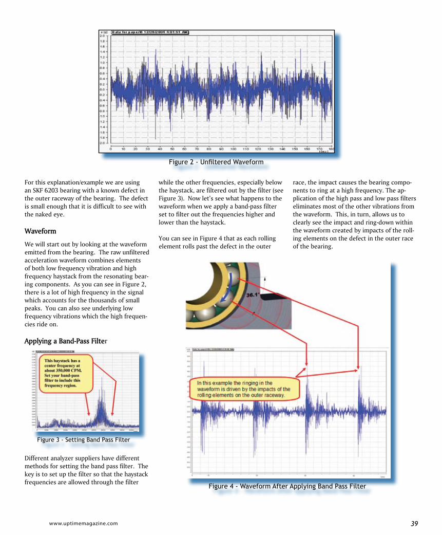
For this explanation/example we are using an SKF 6203 bearing with a known defect in the outer raceway of the bearing. The defect is small enough that it is difficult to see with the naked eye.
Waveform
We will start out by looking at the waveform emitted from the bearing. The raw unfiltered acceleration waveform combines elements of both low frequency vibration and high frequency haystack from the resonating bear-ing components. As you can see in Figure 2, there is a lot of high frequency in the signal which accounts for the thousands of small peaks. You can also see underlying low frequency vibrations which the high frequen-cies ride on.
Applying a Band-Pass Filter
Different analyzer suppliers have different methods for setting the band pass filter. The key is to set up the filter so that the haystack frequencies are allowed through the filter
while the other frequencies, especially below the haystack, are filtered out by the filter (see Figure 3). Now let’s see what happens to the waveform when we apply a band-pass filter set to filter out the frequencies higher and lower than the haystack.
You can see in Figure 4 that as each rolling element rolls past the defect in the outer
Figure 2 - Unfiltered Waveform
Figure 4 - Waveform After Applying Band Pass Filter
Figure 3 - Setting Band Pass Filter
race, the impact causes the bearing compo-nents to ring at a high frequency. The ap-plication of the high pass and low pass filters eliminates most of the other vibrations from the waveform. This, in turn, allows us to clearly see the impact and ring-down within the waveform created by impacts of the roll-ing elements on the defect in the outer race of the bearing.
february 200640
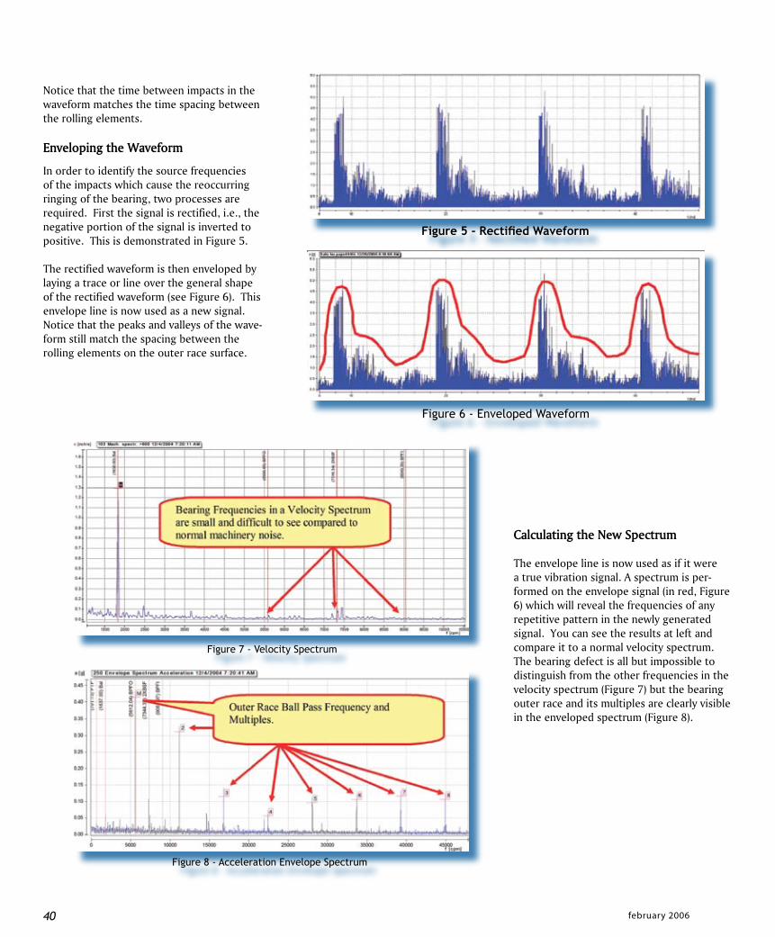
Notice that the time between impacts in the waveform matches the time spacing between the rolling elements.
Enveloping the Waveform
In order to identify the source frequencies of the impacts which cause the reoccurring ringing of the bearing, two processes are required. First the signal is rectified, i.e., the negative portion of the signal is inverted to positive. This is demonstrated in Figure 5.
The rectified waveform is then enveloped by laying a trace or line over the general shape of the rectified waveform (see Figure 6). This envelope line is now used as a new signal.Notice that the peaks and valleys of the wave-form still match the spacing between the rolling elements on the outer race surface.
Calculating the New Spectrum
The envelope line is now used as if it were a true vibration signal. A spectrum is per-formed on the envelope signal (in red, Figure 6) which will reveal the frequencies of any repetitive pattern in the newly generated signal. You can see the results at left and compare it to a normal velocity spectrum. The bearing defect is all but impossible to distinguish from the other frequencies in the velocity spectrum (Figure 7) but the bearing outer race and its multiples are clearly visible in the enveloped spectrum (Figure 8).
40
Figure 6 - Enveloped Waveform
Figure 5 - Rectified Waveform
Figure 7 - Velocity Spectrum
Figure 8 - Acceleration Envelope Spectrum

www.uptimemagazine.com 41
In Figure 9, we have displayed a wa-terfall of acceleration envelope spec-trums and a trend of the bearing’s outer race frequency. This helps you track and identify the increase in intensity of the bearing outer race defect over time.
Other Sources of the “Haystack”
If a Haystack is present in an ac-celeration spectrum, it is important to understand that there are other possible causes aside from bearing damage. As mentioned previously, such conditions as a shaft rub, pump cavitation, steam noise, rubbing seals, process noise, and audible noise can also drive the bearing housing to ring and display the haystack pattern. The big difference is that the source generally consists of random impacts, and not regularly spaced impacts. The envelope can
Figure 9 - Waterfall of Acceleration Envelope Spectrums & Trend
Serving the predictive maintenance community for over 15 years with: Balancing Correction Weights - Over 5 million weights in stock - 100 sizes in 15 styles Custom metal stampings - Quotes from print or sample Alignment Shims Same day shipping No order too small!
Do you BALANCE ROTATING MACHINERY ? CDI is your balancing correction weight specialist!
CD Internat ional , Inc . www.balancingweights .com
5540 Shimervi l le Rd. Clarence, NY 14031 Tel : 716-741-8851 Fax: 716-741-0022
e-mai l : info@balancingweights .com
CD International, Inc. www.balancingweights.com
february 200642
is fast becoming a key element in the early detection of failing bearings in most aggressive Condition-Based Main-tenance Programs. Don’t miss using this excellent technique to get ahead of rolling element bearing problems in your facility.
Greg received his BS Degree from Michigan Technological University in 1982 where he was a member of The National Deans List. Since his employ-ment with IRD Mechanalysis in the mid 1980s, he has worked for several major vibration measurement companies as well as provided condition based main-tenance programs for a number of min-ing and paper companies. In 1995, he
joined Prüftechnik AG where he helped with product and market development. Since 1999 he has worked with Ludeca, Inc. the exclusive US distributor for Prüftechnik products. Greg resides in Gardnerville Nevada with his wife Cindy where they have 5 children and 1 grand child. He enjoys Skiing, Motocross, and is a Sail Plane (Glider) Pilot. Greg can be contacted at [email protected] or at (775) 265-6650.
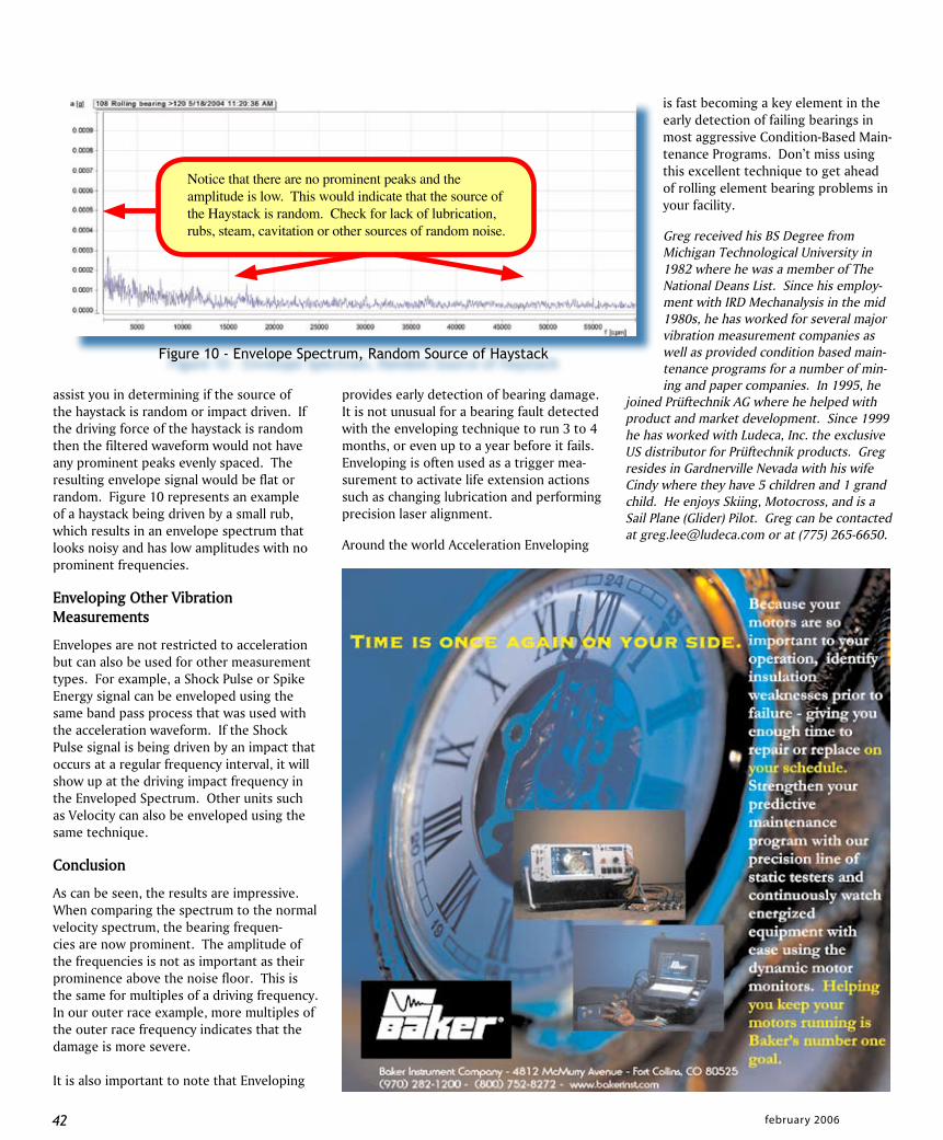
assist you in determining if the source of the haystack is random or impact driven. If the driving force of the haystack is random then the filtered waveform would not have any prominent peaks evenly spaced. The resulting envelope signal would be flat or random. Figure 10 represents an example of a haystack being driven by a small rub, which results in an envelope spectrum that looks noisy and has low amplitudes with no prominent frequencies.
Enveloping Other Vibration Measurements
Envelopes are not restricted to acceleration but can also be used for other measurement types. For example, a Shock Pulse or Spike Energy signal can be enveloped using the same band pass process that was used with the acceleration waveform. If the Shock Pulse signal is being driven by an impact that occurs at a regular frequency interval, it will show up at the driving impact frequency in the Enveloped Spectrum. Other units such as Velocity can also be enveloped using the same technique.
Conclusion
As can be seen, the results are impressive. When comparing the spectrum to the normal velocity spectrum, the bearing frequen-cies are now prominent. The amplitude of the frequencies is not as important as their prominence above the noise floor. This is the same for multiples of a driving frequency. In our outer race example, more multiples of the outer race frequency indicates that the damage is more severe.
It is also important to note that Enveloping
provides early detection of bearing damage. It is not unusual for a bearing fault detected with the enveloping technique to run 3 to 4 months, or even up to a year before it fails. Enveloping is often used as a trigger mea-surement to activate life extension actions such as changing lubrication and performing precision laser alignment.
Around the world Acceleration Enveloping
Figure 10 - Envelope Spectrum, Random Source of Haystack