Embed Size (px)
Citation preview
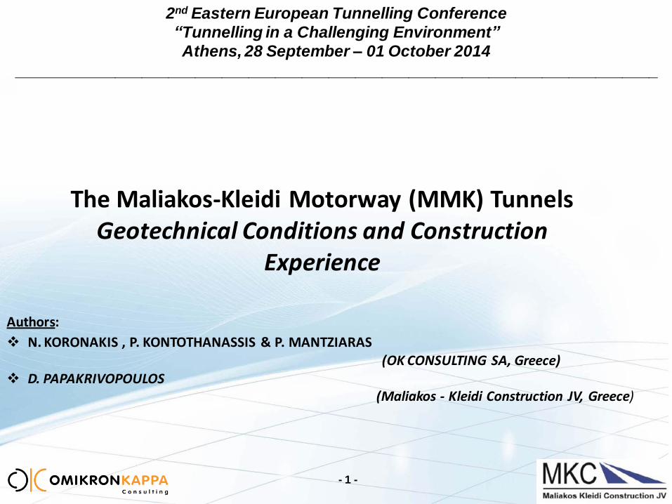
2nd Eastern European Tunnelling Conference
“Tunnelling in a Challenging Environment”
Athens, 28 September – 01 October 2014
________________________________________________________________________
Authors:
N. KORONAKIS , P. KONTOTHANASSIS & P. MANTZIARAS (OK CONSULTING SA, Greece)
D. PAPAKRIVOPOULOS (Maliakos - Kleidi Construction JV, Greece)
The Maliakos-Kleidi Motorway (MMK) Tunnels Geotechnical Conditions and Construction
Experience
- 1 -

MALIAKOS – KLEIDI MOTORWAY (MMK) TUNNELS – GEOTECHNICAL CONDITIONS AND CONSTRUCTION EXPERIENCE
Project Section Tunnel L (m) Geology
Evagelismos to Rapsani Tembi 1 (T1) 2 x 2,000 Amphibolies, Amphibolite Schists, Marbles, Phyllites
Tembi 2 (T2) 2 x 6,000 Phyllites, and crystalline Limestones
Platamonas to Skotina T3 2 x 2,780 Peridotites and Limestones
Total Length of MMK tunnels : 21.5 km
Project’s Tunnels Nomenclature:
branch driving to Maliakos (ATHENS) : the South Bound
branch driving to Kleidi (THESSALONIKI) : the North Bound
- 2 -
MALIAKOS – KLEIDI MOTORWAY (MMK) TUNNELS – GEOTECHNICAL CONDITIONS AND CONSTRUCTION EXPERIENCE
The presentation is structured to:
- 3 -
present the key aspects of the MMK tunnels’ design
present the most striking cases from the tunnels’ construction
MALIAKOS – KLEIDI MOTORWAY (MMK) TUNNELS – GEOTECHNICAL CONDITIONS AND CONSTRUCTION EXPERIENCE
Design of the MMK Tunnels The Role of the Tunnel Design Consortium
(ILF Austria, OK CONSULTING Greece, HOCHTIEF Consult Germany)
- 4 -
to elaborate safe, competent and efficient designs for the E&S, the Final Lining and the
Fit out details of the MMK tunnels, which:
i. comply with the Contractual Requirements and the International Standards;
ii. fit to the time schedule of the MKC-JV (HOCHTIEF/AKTOR, J&P, VINCI, AEGEK, ATHENA);
iii. account for different tunneling approaches & equipment, on request by each of the construction firms;
iv. can be readily approved by the Supervising Authority (the Independent Engineer)
to provide continuous design consultation on Site during construction (by
continuous construction Follow Up ) in updating the design to address unpredictable
conditions;
MALIAKOS – KLEIDI MOTORWAY (MMK) TUNNELS – GEOTECHNICAL CONDITIONS AND CONSTRUCTION EXPERIENCE
Design of the MMK Tunnels Tunnel Designs
- 5 -
i. The Preliminary Design for the 3-lane section
ii. The Geological Studies
iii. The geotechnical investigation campaign (to enhance the geological/geotechnical data basis
along the tunnel stretches towards risk mitigation of unpredictable underground
conditions)
iv. The Geotechnical Interpretation
v. The Final Designs (Portal & Portal structures, Excavation & Support, Final Lining, Hydraulic
facilities and Fit-out details)
vi. Fast Track Designs (special designs ordered to speed up the start-up of tunnelling)
MALIAKOS – KLEIDI MOTORWAY (MMK) TUNNELS – GEOTECHNICAL CONDITIONS AND CONSTRUCTION EXPERIENCE
- 6 -
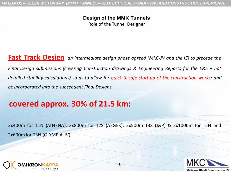
Fast Track Design, an intermediate design phase agreed (MKC-JV and the IE) to precede the
Final Design submissions (covering Construction drawings & Engineering Reports for the E&S – not
detailed stability calculations) so as to allow for quick & safe start-up of the construction works; and
be incorporated into the subsequent Final Designs.
covered approx. 30% of 21.5 km:
2x400m for T1N (ATHENA), 2x800m for T2S (AEGEK), 2x500m T3S (J&P) & 2x1000m for T2N and
2x600m for T3N (OLYMPIA JV).
Design of the MMK Tunnels
Role of the Tunnel Designer
MALIAKOS – KLEIDI MOTORWAY (MMK) TUNNELS – GEOTECHNICAL CONDITIONS AND CONSTRUCTION EXPERIENCE
Main Aspects of the Safety Concept of the MMK Tunnels (substantiated by Risk Analysis Study)
- 7 -
MALIAKOS – KLEIDI MOTORWAY (MMK) TUNNELS – GEOTECHNICAL CONDITIONS AND CONSTRUCTION EXPERIENCE
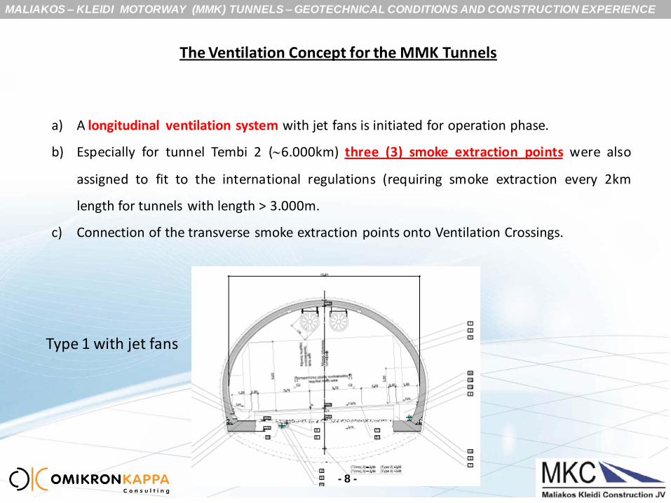
The Ventilation Concept for the MMK Tunnels
a) A longitudinal ventilation system with jet fans is initiated for operation phase.
b) Especially for tunnel Tembi 2 (6.000km) three (3) smoke extraction points were also
assigned to fit to the international regulations (requiring smoke extraction every 2km
length for tunnels with length > 3.000m.
c) Connection of the transverse smoke extraction points onto Ventilation Crossings.
- 8 -
Type 1 with jet fans

MALIAKOS – KLEIDI MOTORWAY (MMK) TUNNELS – GEOTECHNICAL CONDITIONS AND CONSTRUCTION EXPERIENCE
Structural Requirements for the MMK tunnels
- 9 -
•Application of the NATM for the excavation-support and final lining of the tunnels
•Minimum concrete quality for permanent structures and structure components C30/37
•Minimum thickness of permanent lining ≥40cm for the main tunnel sections
•Permanent lining without reinforcement depending on the rock mass conditions
•Crack width limitation at: 0.30mm in case of reinforced lining; 1.0mm for the unreinforced sections
•Shrinkage and creeping acc to DIN 1045-1
•Average construction temperature of 150C and a difference Δt of ±100C
•Consideration of impacts of explosion on the final lining
•Consideration of effect of fire to the final lining (use of increased cover of the reinforcement 60mm)
MALIAKOS – KLEIDI MOTORWAY (MMK) TUNNELS – GEOTECHNICAL CONDITIONS AND CONSTRUCTION EXPERIENCE
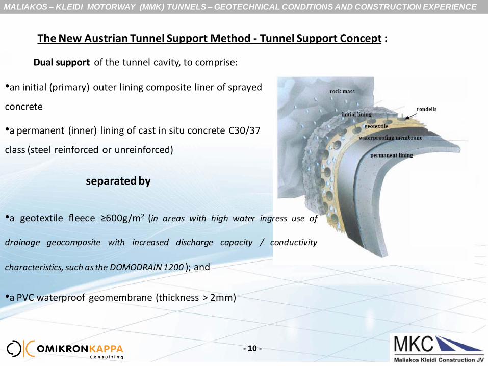
The New Austrian Tunnel Support Method - Tunnel Support Concept :
•an initial (primary) outer lining composite liner of sprayed
concrete
•a permanent (inner) lining of cast in situ concrete C30/37
class (steel reinforced or unreinforced)
separated by
•a geotextile fleece ≥600g/m2 (in areas with high water ingress use of
drainage geocomposite with increased discharge capacity / conductivity
characteristics, such as the DOMODRAIN 1200 ); and
•a PVC waterproof geomembrane (thickness > 2mm)
Dual support of the tunnel cavity, to comprise:
- 10 -
MALIAKOS – KLEIDI MOTORWAY (MMK) TUNNELS – GEOTECHNICAL CONDITIONS AND CONSTRUCTION EXPERIENCE
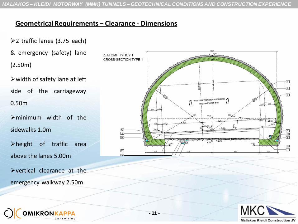
Geometrical Requirements – Clearance - Dimensions
2 traffic lanes (3.75 each)
& emergency (safety) lane
(2.50m)
width of safety lane at left
side of the carriageway
0.50m
minimum width of the
sidewalks 1.0m
height of traffic area
above the lanes 5.00m
vertical clearance at the
emergency walkway 2.50m
- 11 -

MALIAKOS – KLEIDI MOTORWAY (MMK) TUNNELS – GEOTECHNICAL CONDITIONS AND CONSTRUCTION EXPERIENCE
vault : steel reinforced foundation (deep invert el-2.95) : steel reinforced
- 12 -
vault : steel reinforced / unreinforced foundation (beams – shallow invert el-2.65) : steel reinforced
Three Basic Types of Final Lining (FL) – main tunnel
MALIAKOS – KLEIDI MOTORWAY (MMK) TUNNELS – GEOTECHNICAL CONDITIONS AND CONSTRUCTION EXPERIENCE
- 13 -
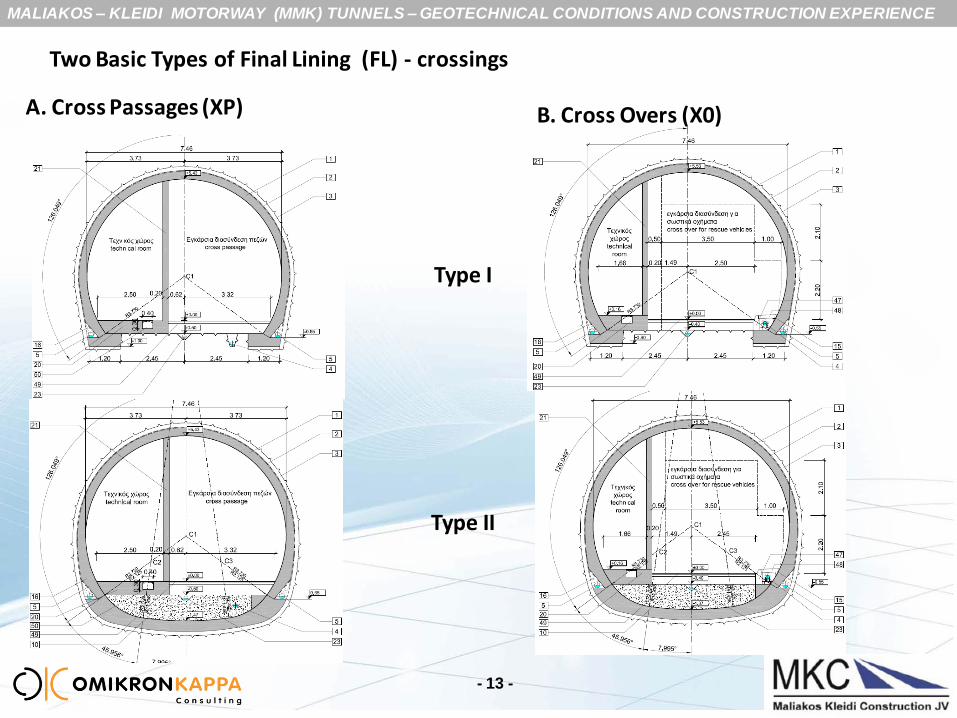
Two Basic Types of Final Lining (FL) - crossings
A. Cross Passages (XP) B. Cross Overs (X0)
Type I
Type II

MALIAKOS – KLEIDI MOTORWAY (MMK) TUNNELS – GEOTECHNICAL CONDITIONS AND CONSTRUCTION EXPERIENCE
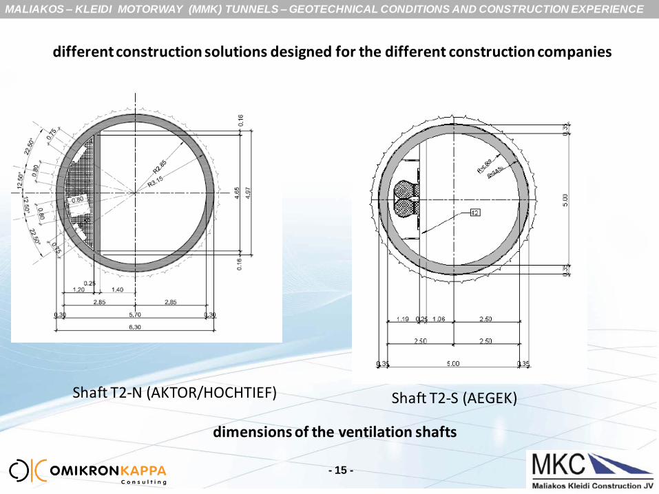
different construction solutions designed for the different construction companies
- 14 -
layout of the joint between vault and foundation
MALIAKOS – KLEIDI MOTORWAY (MMK) TUNNELS – GEOTECHNICAL CONDITIONS AND CONSTRUCTION EXPERIENCE
different construction solutions designed for the different construction companies
- 15 -
Shaft T2-N (AKTOR/HOCHTIEF) Shaft T2-S (AEGEK)
dimensions of the ventilation shafts

MALIAKOS – KLEIDI MOTORWAY (MMK) TUNNELS – GEOTECHNICAL CONDITIONS AND CONSTRUCTION EXPERIENCE
preparation of alternative designs to speed up the construction schedule:
- 16 -
alternative /final concept (with Ventilation Building)
The configuration of the Central Ventilation Facility
original concept (with ventilation chamber)
MALIAKOS – KLEIDI MOTORWAY (MMK) TUNNELS – GEOTECHNICAL CONDITIONS AND CONSTRUCTION EXPERIENCE
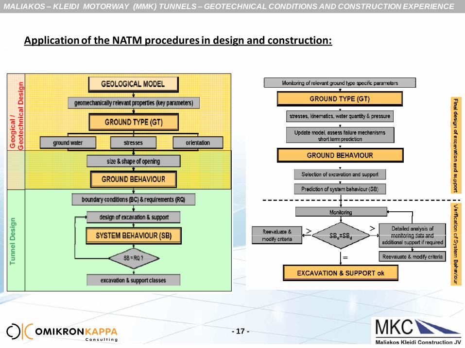
Application of the NATM procedures in design and construction:
- 17 -
MALIAKOS – KLEIDI MOTORWAY (MMK) TUNNELS – GEOTECHNICAL CONDITIONS AND CONSTRUCTION EXPERIENCE
- 18 -
The Excavation & Support (E&S) Design must account for :
the variability of the geotechnical conditions
the variability of the stress conditions
the variability in the groundwater conditions
the non-continuity in the geotechnical information along the tunnel
stretches, which requires interpolation towards the realistic prediction of the
actual geotechnical risks;
interaction with the utilities involved with the alignment (i.e. Nat. Gas
Pipeline, influence to the supply water springs at the Platamon area)
MALIAKOS – KLEIDI MOTORWAY (MMK) TUNNELS – GEOTECHNICAL CONDITIONS AND CONSTRUCTION EXPERIENCE
- 19 -
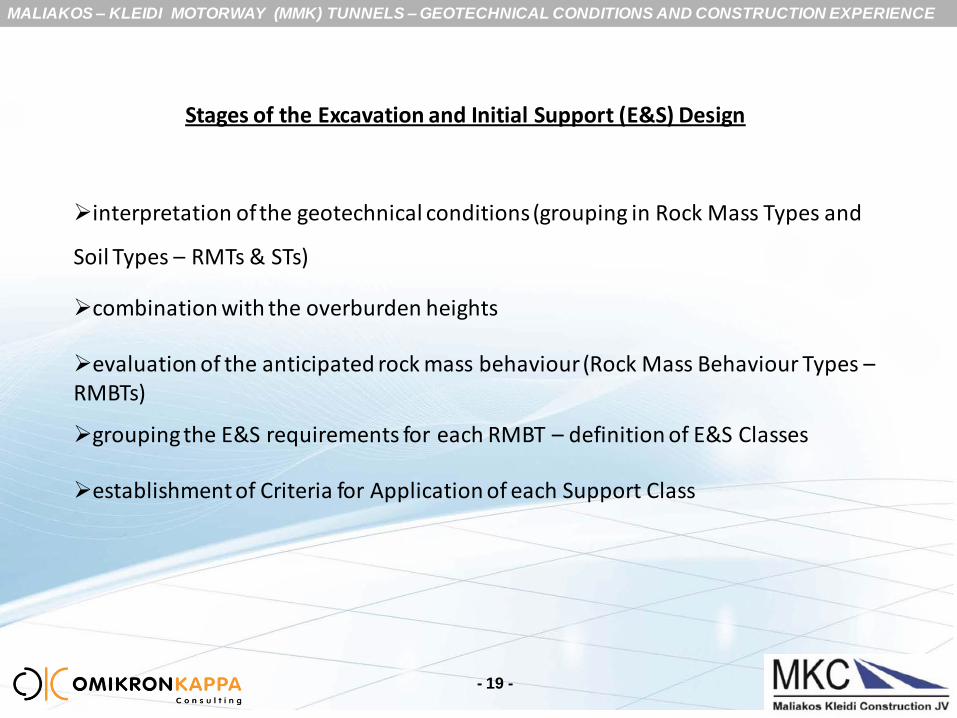
interpretation of the geotechnical conditions (grouping in Rock Mass Types and
Soil Types – RMTs & STs)
combination with the overburden heights
evaluation of the anticipated rock mass behaviour (Rock Mass Behaviour Types – RMBTs)
grouping the E&S requirements for each RMBT – definition of E&S Classes
establishment of Criteria for Application of each Support Class
Stages of the Excavation and Initial Support (E&S) Design

MALIAKOS – KLEIDI MOTORWAY (MMK) TUNNELS – GEOTECHNICAL CONDITIONS AND CONSTRUCTION EXPERIENCE
Rock Mass Conditions – Rock Mass Types – Tunnel T1
- 20 -
Significantly broad range of rock mass qualities
MALIAKOS – KLEIDI MOTORWAY (MMK) TUNNELS – GEOTECHNICAL CONDITIONS AND CONSTRUCTION EXPERIENCE
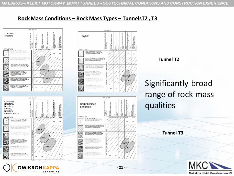
Rock Mass Conditions – Rock Mass Types – TunnelsT2 , T3
Tunnel T2
Tunnel T3
- 21 -
Significantly broad range of rock mass qualities
MALIAKOS – KLEIDI MOTORWAY (MMK) TUNNELS – GEOTECHNICAL CONDITIONS AND CONSTRUCTION EXPERIENCE
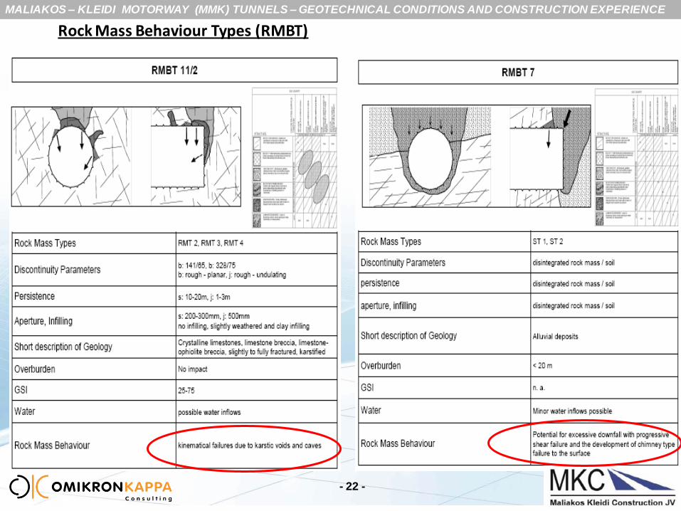
Rock Mass Behaviour Types (RMBT)
- 22 -
MALIAKOS – KLEIDI MOTORWAY (MMK) TUNNELS – GEOTECHNICAL CONDITIONS AND CONSTRUCTION EXPERIENCE
- 23 -
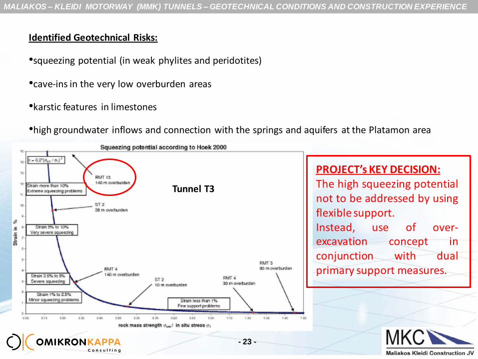
Identified Geotechnical Risks:
•squeezing potential (in weak phylites and peridotites)
•cave-ins in the very low overburden areas
•karstic features in limestones
•high groundwater inflows and connection with the springs and aquifers at the Platamon area
Tunnel T3
PROJECT’s KEY DECISION: The high squeezing potential not to be addressed by using flexible support. Instead, use of over-excavation concept in conjunction with dual primary support measures.
MALIAKOS – KLEIDI MOTORWAY (MMK) TUNNELS – GEOTECHNICAL CONDITIONS AND CONSTRUCTION EXPERIENCE
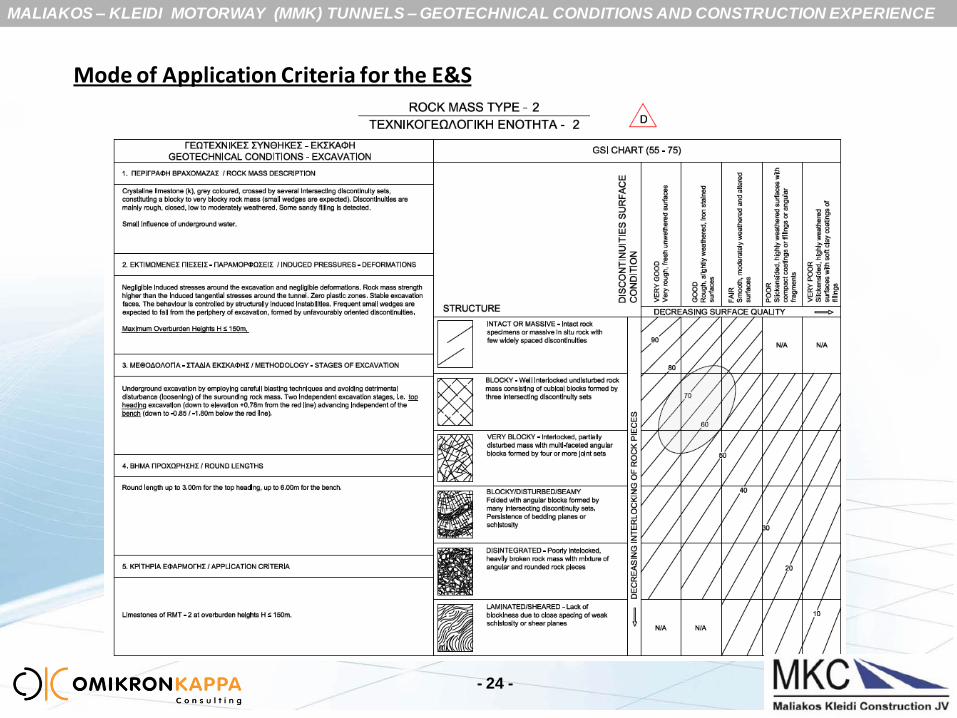
Mode of Application Criteria for the E&S
- 24 -
MALIAKOS – KLEIDI MOTORWAY (MMK) TUNNELS – GEOTECHNICAL CONDITIONS AND CONSTRUCTION EXPERIENCE
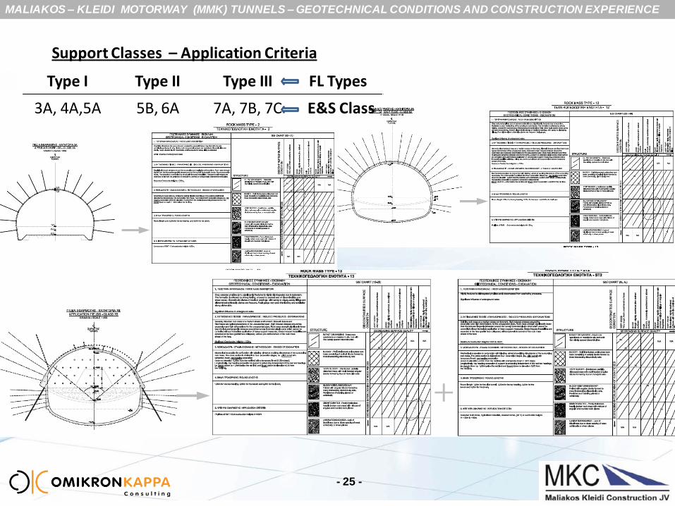
Support Classes – Application Criteria
- 25 -
SC-3A, 4A, 5A, 5B, 6A,7A-B-C
Type I Type II Type III FL Types
3A, 4A,5A 5B, 6A 7A, 7B, 7C E&S Class
MALIAKOS – KLEIDI MOTORWAY (MMK) TUNNELS – GEOTECHNICAL CONDITIONS AND CONSTRUCTION EXPERIENCE
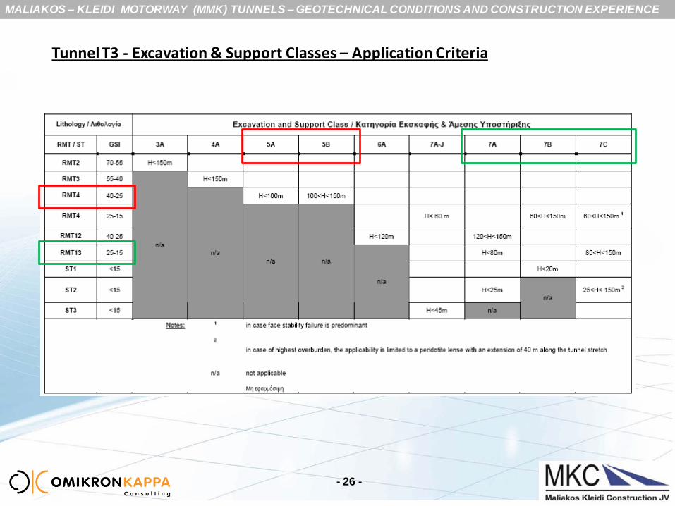
Tunnel T3 - Excavation & Support Classes – Application Criteria
- 26 -
MALIAKOS – KLEIDI MOTORWAY (MMK) TUNNELS – GEOTECHNICAL CONDITIONS AND CONSTRUCTION EXPERIENCE
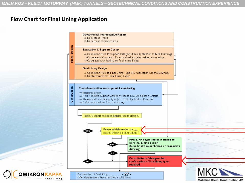
Flow Chart for Final Lining Application
- 27 -
MALIAKOS – KLEIDI MOTORWAY (MMK) TUNNELS – GEOTECHNICAL CONDITIONS AND CONSTRUCTION EXPERIENCE
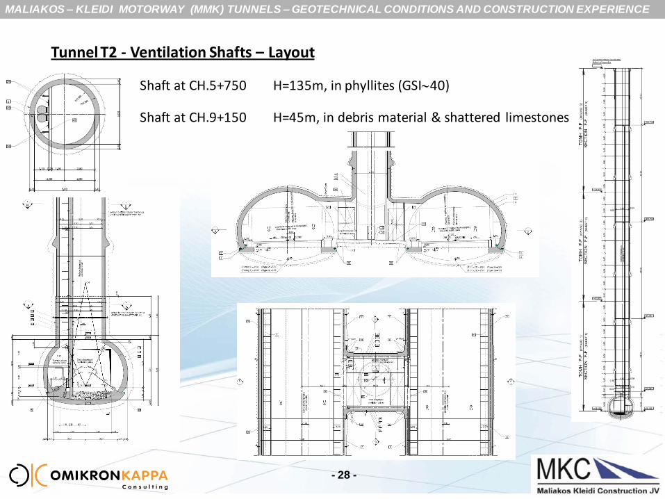
Tunnel T2 - Ventilation Shafts – Layout
Shaft at CH.5+750 H=135m, in phyllites (GSI40)
Shaft at CH.9+150 H=45m, in debris material & shattered limestones
- 28 -

MALIAKOS – KLEIDI MOTORWAY (MMK) TUNNELS – GEOTECHNICAL CONDITIONS AND CONSTRUCTION EXPERIENCE
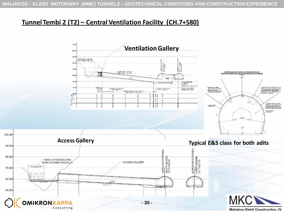
Tunnel Tembi 2 (T2) – Central Ventilation Facility (CH.7+580)
Plan View
Construction Sequence
- 29 -
•access gallery L=97m
•ventilation complex : ventilation crossing
air duct
ventilation gallery (L=100m)
Geotechnical conditions: competent limestones GSI 40- 55
MALIAKOS – KLEIDI MOTORWAY (MMK) TUNNELS – GEOTECHNICAL CONDITIONS AND CONSTRUCTION EXPERIENCE
Tunnel Tembi 2 (T2) – Central Ventilation Facility (CH.7+580)
Ventilation Gallery
Access Gallery
- 30 -
Typical E&S class for both adits

MALIAKOS – KLEIDI MOTORWAY (MMK) TUNNELS – GEOTECHNICAL CONDITIONS AND CONSTRUCTION EXPERIENCE
Tunnel Tembi 2 (T2) – Central Ventilation Facility (CH.7+580)
- 31 -
Aspects of Ventilation Complex
6.00 x 4.60 (H:W)

MALIAKOS – KLEIDI MOTORWAY (MMK) TUNNELS – GEOTECHNICAL CONDITIONS AND CONSTRUCTION EXPERIENCE
Tunnel Tembi 2 (T2) – Central Ventilation Facility (CH.7+580)
Excavation sequence of the Ventilation complex (ventilation crossing & duct)
- 32 -

MALIAKOS – KLEIDI MOTORWAY (MMK) TUNNELS – GEOTECHNICAL CONDITIONS AND CONSTRUCTION EXPERIENCE
Tunnel Tembi 2 (T2) – Ventilation Shaft H=135m (CH.5+750, Φ5000)
- 33 -
•excavation from top to down
•raise boring (Φ1000mm)
•material feeding from the top - spoil removal from the bottom
•competent phyllites (GSI40)
•time for E&S : 6 months
•time for concreting: 3 months (27 blocks, standard block H=5.00m)

MALIAKOS – KLEIDI MOTORWAY (MMK) TUNNELS – GEOTECHNICAL CONDITIONS AND CONSTRUCTION EXPERIENCE
Tunnel Tembi 2 (T2) – Ventilation Shaft H= 45m (CH.9+150, Φ5700)
- 34 -
•excavation from top to down
•material feeding from the top - spoil removal from the top
•Limestone debris and shattered limestones
•time for E&S : 4 weeks
•time for concreting: 5 weeks (19 blocks, standard block H=2.50m )
MALIAKOS – KLEIDI MOTORWAY (MMK) TUNNELS – GEOTECHNICAL CONDITIONS AND CONSTRUCTION EXPERIENCE
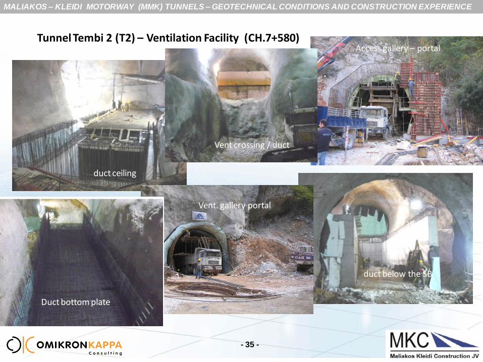
Tunnel Tembi 2 (T2) – Ventilation Facility (CH.7+580)
- 35 -
duct ceiling
Access gallery – portal
Vent. gallery portal
duct below the SB
Vent crossing / duct
Duct bottom plate
MALIAKOS – KLEIDI MOTORWAY (MMK) TUNNELS – GEOTECHNICAL CONDITIONS AND CONSTRUCTION EXPERIENCE
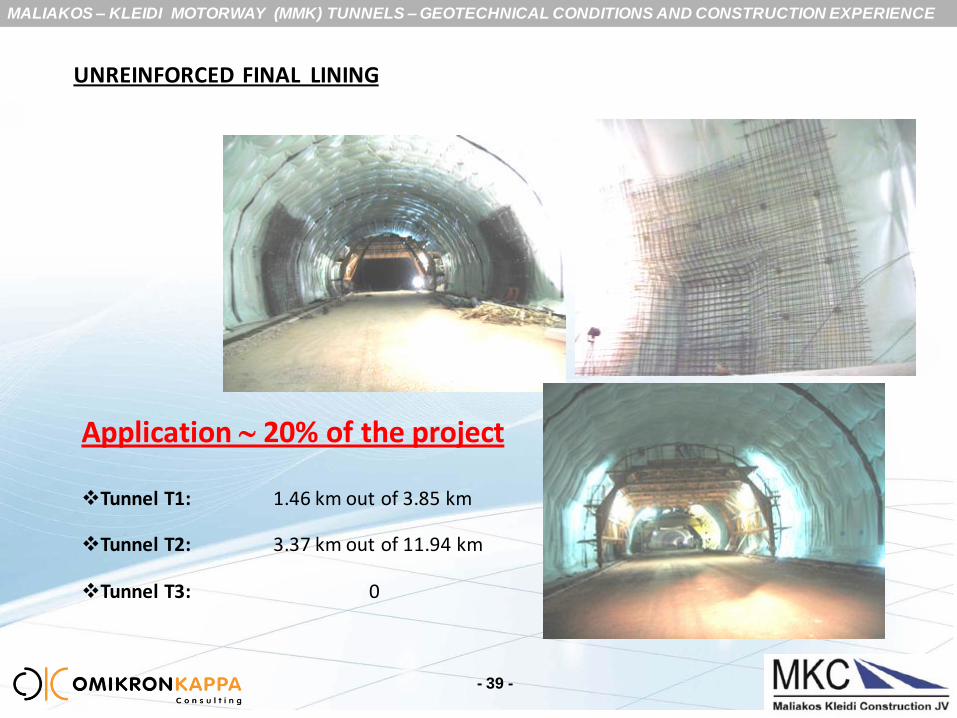
UNREINFORCED FINAL LINING
Principles of designing the unreinforced lining in the MMK tunnels:
Unreinforced in the main tunnel sections (depending on rock mass conditions), however
in blocks with niches (drainage & EDP) where an unreinforced lining is applied , the area
around the niche is steel reinforced
Steel reinforced lining adopted in:
the crossings
the intersection blocks of the main tunnel
the shafts and complex underground spaces
sections susceptible to seismic forces (i.e. for the C&C structures,
low overburden areas)
- 36 -

MALIAKOS – KLEIDI MOTORWAY (MMK) TUNNELS – GEOTECHNICAL CONDITIONS AND CONSTRUCTION EXPERIENCE
UNREINFORCED FINAL LINING
Unreinforced lining designated only for the FL types 1 and 2 (NOT for Type 3)
concrete quality C30/37; de-moulding concrete strength >2MPa
min thickness of vault 45cm
application in competent rock mass with E>1GPa
maximum crack width: 1.0mm

MALIAKOS – KLEIDI MOTORWAY (MMK) TUNNELS – GEOTECHNICAL CONDITIONS AND CONSTRUCTION EXPERIENCE
UNREINFORCED FINAL LINING
Application in blocks with a niche
DRAINAGE NICHE
EMERGENCY (EDP) NICHE
MALIAKOS – KLEIDI MOTORWAY (MMK) TUNNELS – GEOTECHNICAL CONDITIONS AND CONSTRUCTION EXPERIENCE
- 39 -
Application 20% of the project
Tunnel T1: 1.46 km out of 3.85 km
Tunnel T2: 3.37 km out of 11.94 km
Tunnel T3: 0
UNREINFORCED FINAL LINING
MALIAKOS – KLEIDI MOTORWAY (MMK) TUNNELS – GEOTECHNICAL CONDITIONS AND CONSTRUCTION EXPERIENCE
SPECIAL CONDITIONS ENCOUNTERED IN THE EXCAVATION & SUPPORT
- 40 -
tunnelling under low overburden (as low as 6m)
tunnelling under high overburden (T2 >250m, T3 150m)
formation of complex underground spaces for the ventilation facilities
extremely heterogeneous masses and mixed face conditions
unprecedented face instabilities
high convergence rates / delayed deformations – need for
rehabilitation works
significant groundwater inflows (75l/s)
MALIAKOS – KLEIDI MOTORWAY (MMK) TUNNELS – GEOTECHNICAL CONDITIONS AND CONSTRUCTION EXPERIENCE
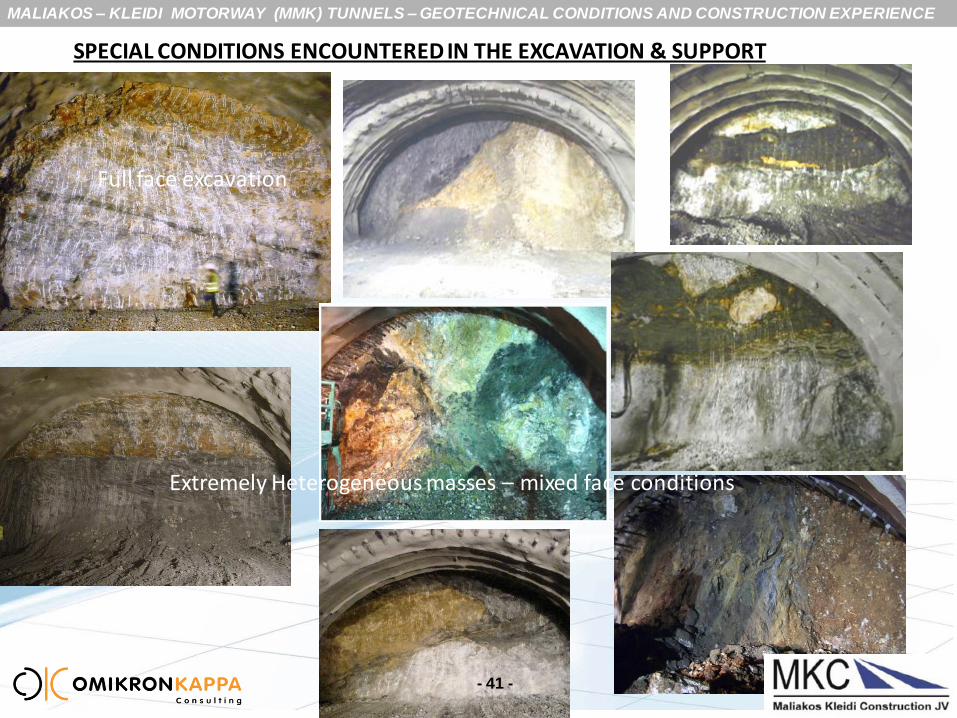
Full face excavation
SPECIAL CONDITIONS ENCOUNTERED IN THE EXCAVATION & SUPPORT
- 41 -
Extremely Heterogeneous masses – mixed face conditions
MALIAKOS – KLEIDI MOTORWAY (MMK) TUNNELS – GEOTECHNICAL CONDITIONS AND CONSTRUCTION EXPERIENCE
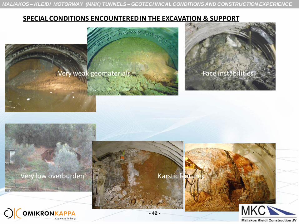
- 42 -
Very weak geomaterials
Very low overburden Karstic features
Face instabilities
SPECIAL CONDITIONS ENCOUNTERED IN THE EXCAVATION & SUPPORT
MALIAKOS – KLEIDI MOTORWAY (MMK) TUNNELS – GEOTECHNICAL CONDITIONS AND CONSTRUCTION EXPERIENCE
SPECIAL CONDITIONS ENCOUNTERED IN THE EXCAVATION & SUPPORT
- 43 -
Most hazardous situations were linked with the tunnels passing through long
zones of weak to very weak geomaterials, esp. in
tunnels T2 (Tembi 2 / phyllites) and
T3 (Platamon / peridotites)

MALIAKOS – KLEIDI MOTORWAY (MMK) TUNNELS – GEOTECHNICAL CONDITIONS AND CONSTRUCTION EXPERIENCE
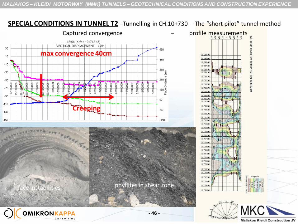
SPECIAL CONDITIONS IN TUNNEL TEMBI TUNNEL 2 (T2)
- 44 -
The “short pilot” tunnel method
Description of tunnel troublesome situation:
Top heading excavation in shattered phyllites GSI10
medium overburden 70m
Severe face instabilities (impossible to address with standard methods, such as: face buttress, intense
fiberglass face bolting etc)
Adverse stress environment
inability to timely implement the support measures for the cavity
early development of high convergences evidence of interaction between the SB and NB
under-performance of the initial lining (overstressing ) – tunnel under-profile
Sections affected: 35m for the SB (leading tunnel) and 25m for the NB (lagging tunnel)
Need for : contingency measures design for immediate tunnel stabilization and
upgrading the safety standards in E&S to advance the tunnels

MALIAKOS – KLEIDI MOTORWAY (MMK) TUNNELS – GEOTECHNICAL CONDITIONS AND CONSTRUCTION EXPERIENCE
SPECIAL CONDITIONS IN TUNNEL T2 -Tunnelling in CH.10+730 – The “short pilot” tunnel method
- 45 -
Tunnel Stabilization
Application of 30cm inner shell of sprayed concrete reinforced with 2#Φ12/15 steel grids
MALIAKOS – KLEIDI MOTORWAY (MMK) TUNNELS – GEOTECHNICAL CONDITIONS AND CONSTRUCTION EXPERIENCE
- 46 -
Captured convergence – profile measurements
phyllites in shear zone face instabilities
Creeping
SPECIAL CONDITIONS IN TUNNEL T2 -Tunnelling in CH.10+730 – The “short pilot” tunnel method
max convergence 40cm
MALIAKOS – KLEIDI MOTORWAY (MMK) TUNNELS – GEOTECHNICAL CONDITIONS AND CONSTRUCTION EXPERIENCE
- 47 -
SPECIAL CONDITIONS IN TUNNEL T2 -The “short pilot” tunnel method
Side drifts were rejected (requiring different equipment )
Grout strengthening also rejected (low permeability of the sheared phyllites)
A central short drift in advance of the main tunnel
was selected to provide the confinement of the weak phyllites below the forepoling umbrella
excavation is executed from the main tunnel, while the section is demolished on advancement of
the main tunnel
effective to deal with face instabilities in practically cohesionless geomaterials – where the
standard measures (intense face bolting, shotcrete, forepolling) proved ineffective
allowance for timely and safe application of the support measures of the cavity (as close to the
face as possible)
constructed with the same equipment deployed for the main tunnel

MALIAKOS – KLEIDI MOTORWAY (MMK) TUNNELS – GEOTECHNICAL CONDITIONS AND CONSTRUCTION EXPERIENCE
- 48 -
SPECIAL CONDITIONS IN TUNNEL T2 -Tunnelling in CH.10+730 – The “short pilot” tunnel method
Short pilot tunnel section Main tunnel section Specifics of the short pilot •max advance 5m •29 pieces of 12m/4m long forepoles Φ114/140 •round length 1.0m •25cm thick shell of f.r. sprayed concrete •HEB140 embedded •no rockbolting
MALIAKOS – KLEIDI MOTORWAY (MMK) TUNNELS – GEOTECHNICAL CONDITIONS AND CONSTRUCTION EXPERIENCE
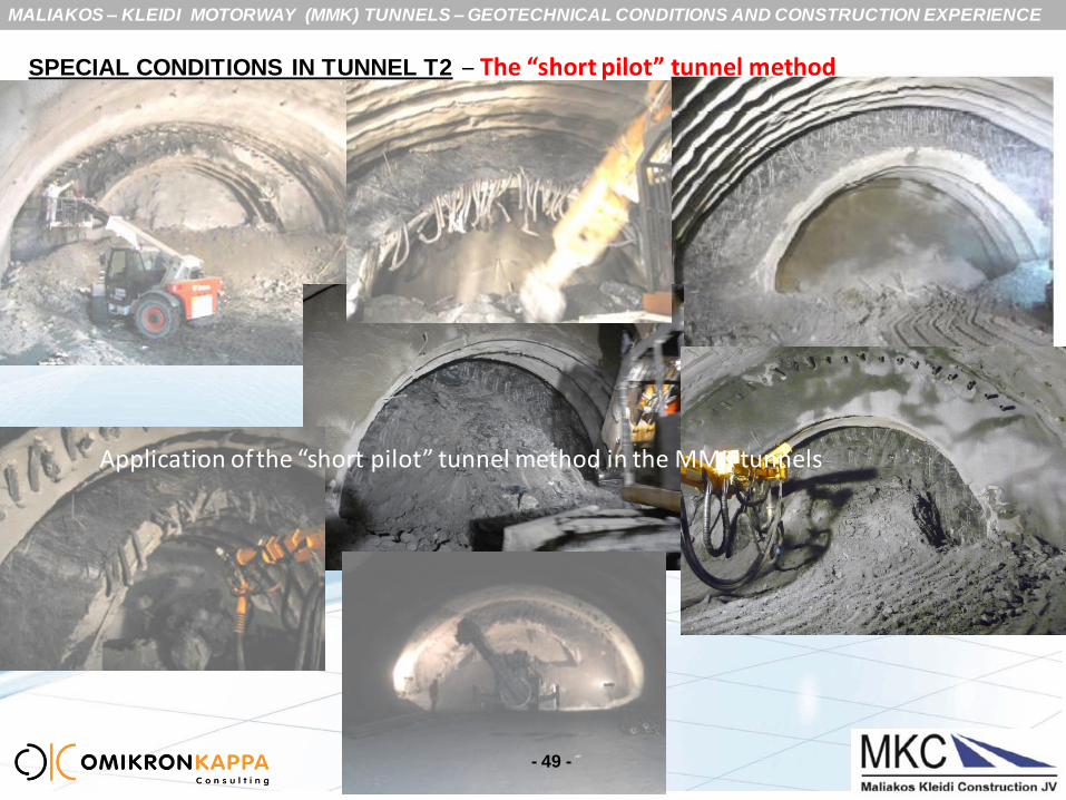
SPECIAL CONDITIONS IN TUNNEL T2 – The “short pilot” tunnel method
- 49 -
Application of the “short pilot” tunnel method in the MMK tunnels
MALIAKOS – KLEIDI MOTORWAY (MMK) TUNNELS – GEOTECHNICAL CONDITIONS AND CONSTRUCTION EXPERIENCE
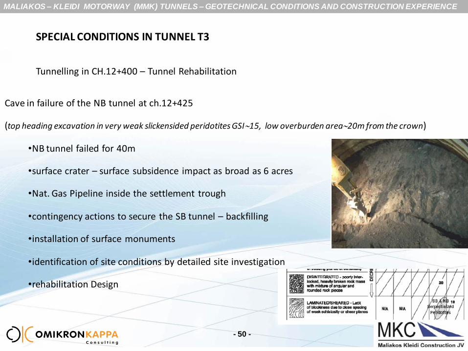
SPECIAL CONDITIONS IN TUNNEL T3
Tunnelling in CH.12+400 – Tunnel Rehabilitation
Cave in failure of the NB tunnel at ch.12+425
(top heading excavation in very weak slickensided peridotites GSI15, low overburden area20m from the crown)
•NB tunnel failed for 40m
•surface crater – surface subsidence impact as broad as 6 acres
•Nat. Gas Pipeline inside the settlement trough
•contingency actions to secure the SB tunnel – backfilling
•installation of surface monuments
•identification of site conditions by detailed site investigation
•rehabilitation Design
- 50 -
MALIAKOS – KLEIDI MOTORWAY (MMK) TUNNELS – GEOTECHNICAL CONDITIONS AND CONSTRUCTION EXPERIENCE
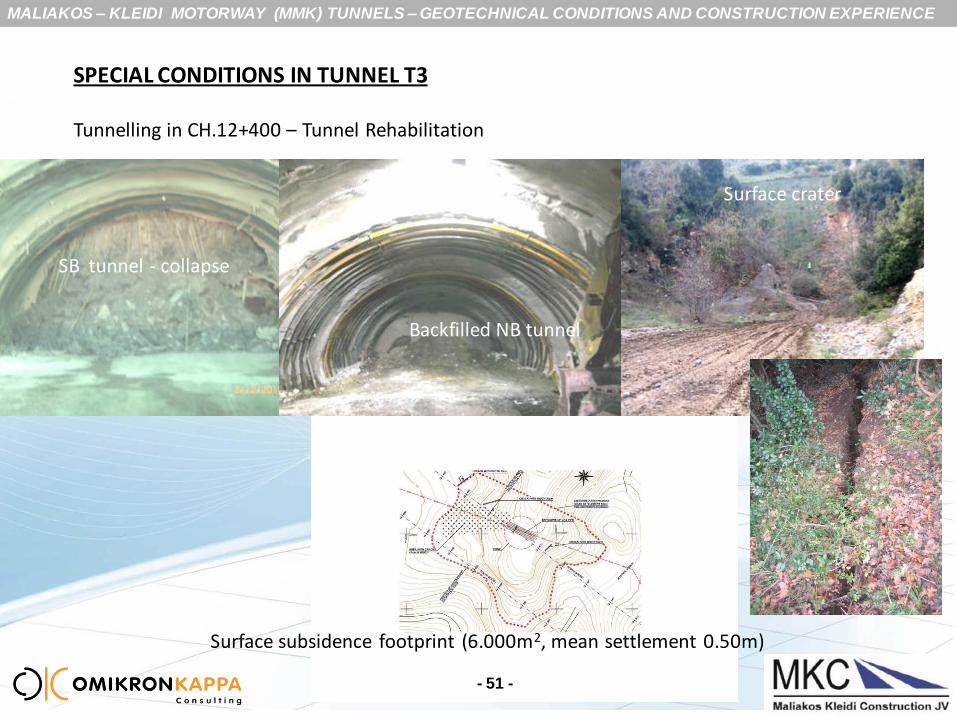
SPECIAL CONDITIONS IN TUNNEL T3
Tunnelling in CH.12+400 – Tunnel Rehabilitation
- 51 -
SB tunnel - collapse
Backfilled NB tunnel
Surface subsidence footprint (6.000m2, mean settlement 0.50m)
Surface crater

MALIAKOS – KLEIDI MOTORWAY (MMK) TUNNELS – GEOTECHNICAL CONDITIONS AND CONSTRUCTION EXPERIENCE
- 52 -
SPECIAL CONDITIONS IN TUNNEL T3
Tunnelling in CH.12+400 – Tunnel Rehabilitation
A pilot tunnel to get through the collapsed zone
no ground improvement unless voids are detected into the collapsed area
Subsequent re-instatement of the tunnel section by demolition of the pilot tunnel
Dimensions of the pilot to be served by the equipment for the main tunnel (forepoling, backhoe etc)
Robust design for the primary support shell (stiff and capable to sustain all dead loading) for both tunnels
Excavation under successive and overlapping forepoling umbrellas
well calibrated numerical modeling for checks of adequacy of the tunnel linings
Restrictions:
Very limited deformations on the NG pipeline
very strict alert levels for movements and well defined contingency actions
MALIAKOS – KLEIDI MOTORWAY (MMK) TUNNELS – GEOTECHNICAL CONDITIONS AND CONSTRUCTION EXPERIENCE
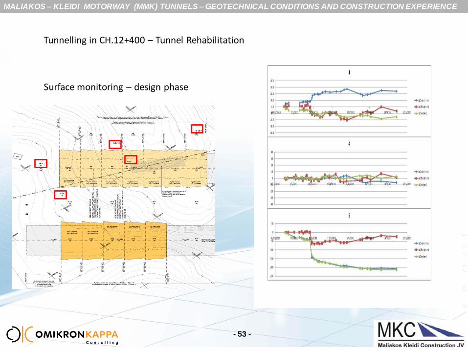
- 53 -
Tunnelling in CH.12+400 – Tunnel Rehabilitation
Surface monitoring – design phase
MALIAKOS – KLEIDI MOTORWAY (MMK) TUNNELS – GEOTECHNICAL CONDITIONS AND CONSTRUCTION EXPERIENCE
- 54 -
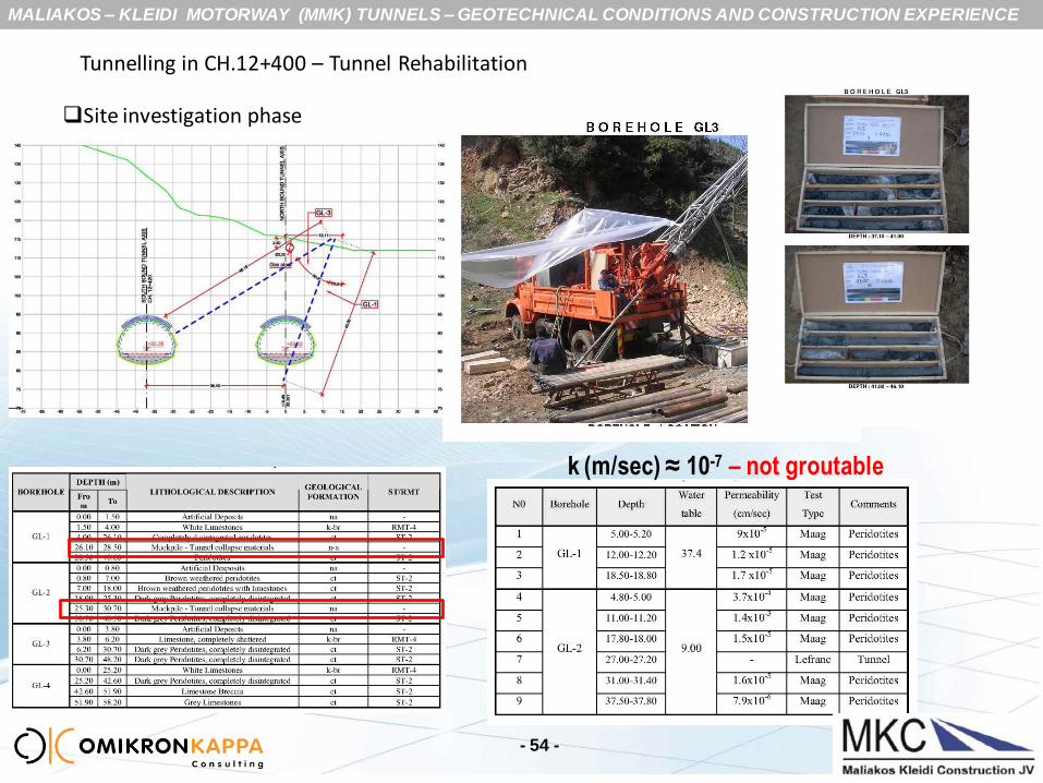
k (m/sec) ≈ 10-7 – not groutable
Tunnelling in CH.12+400 – Tunnel Rehabilitation
Site investigation phase
MALIAKOS – KLEIDI MOTORWAY (MMK) TUNNELS – GEOTECHNICAL CONDITIONS AND CONSTRUCTION EXPERIENCE
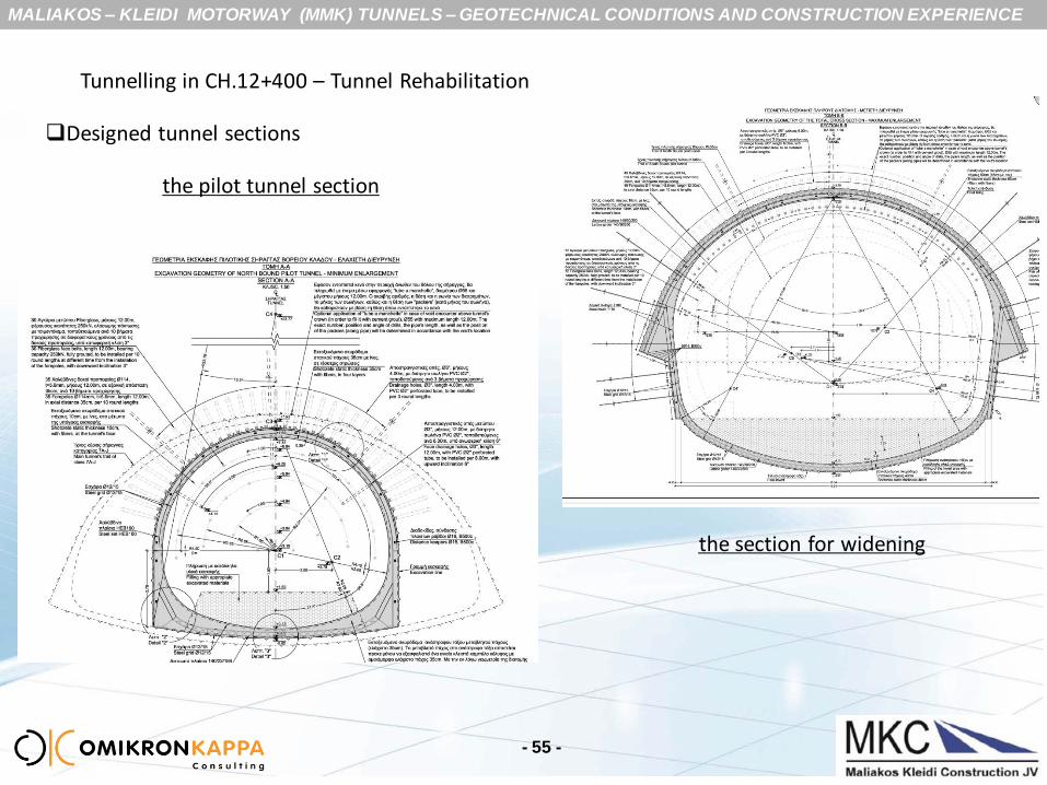
Tunnelling in CH.12+400 – Tunnel Rehabilitation
the pilot tunnel section
the section for widening
- 55 -
Designed tunnel sections

MALIAKOS – KLEIDI MOTORWAY (MMK) TUNNELS – GEOTECHNICAL CONDITIONS AND CONSTRUCTION EXPERIENCE
Tunnelling in CH.12+400 – Tunnel Rehabilitation
- 56 -
Pilot Tunnel section - Support Measures
35 forepoles Φ114/140, 12m overlapping 4m
2 headings (vault and invert)
excavation round 0.80m
35cm thick shotcrete shell (HEB160) + 2#12/15 steel grids
no rockbolts
35cm thick shotcrete invert (LG140/30/200)+ 2#12/15 steel grids
“tube a manchette” grouting for filling voids around the canopy (optional)
Widening Section - Support Measures
49 forepoles Φ114/140, 12m overlapping 4m
3 headings (top – bench – invert)
Excavation/pilot demolition round 0.80m
50cm thick shotcrete double shell in top heading (outer shell LG140/30/200 – inner shell HEB180) +
30cm thick shotcrete shell in bench & invert (LG140/30/200)
6m self drilling rockbolts pairs
Ring closure every 8m rounds

MALIAKOS – KLEIDI MOTORWAY (MMK) TUNNELS – GEOTECHNICAL CONDITIONS AND CONSTRUCTION EXPERIENCE
Section Widening Accurate Model Calibration based on available data
- 57 -
MALIAKOS – KLEIDI MOTORWAY (MMK) TUNNELS – GEOTECHNICAL CONDITIONS AND CONSTRUCTION EXPERIENCE
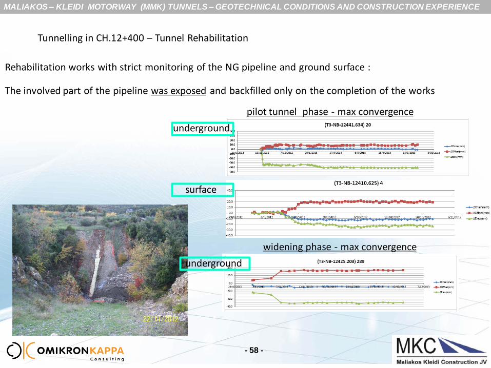
Tunnelling in CH.12+400 – Tunnel Rehabilitation
Rehabilitation works with strict monitoring of the NG pipeline and ground surface :
The involved part of the pipeline was exposed and backfilled only on the completion of the works
- 58 -
pilot tunnel phase - max convergence
widening phase - max convergence
underground
surface
underground
MALIAKOS – KLEIDI MOTORWAY (MMK) TUNNELS – GEOTECHNICAL CONDITIONS AND CONSTRUCTION EXPERIENCE
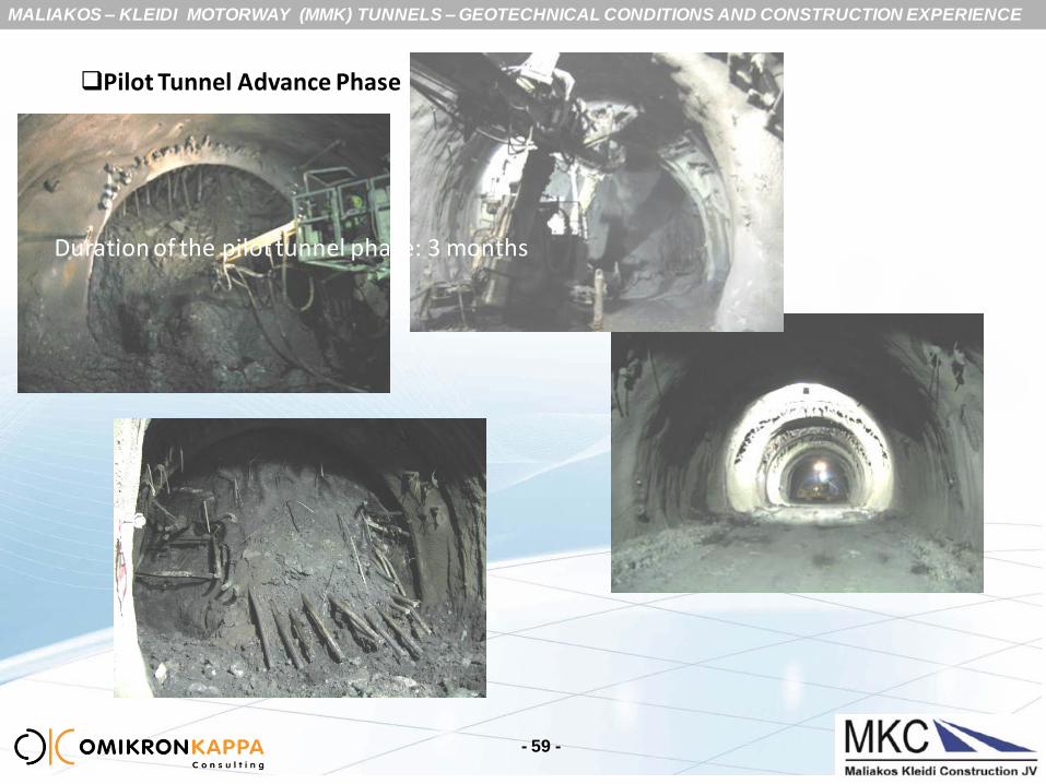
- 59 -
Pilot Tunnel Advance Phase
Duration of the pilot tunnel phase: 3 months
MALIAKOS – KLEIDI MOTORWAY (MMK) TUNNELS – GEOTECHNICAL CONDITIONS AND CONSTRUCTION EXPERIENCE
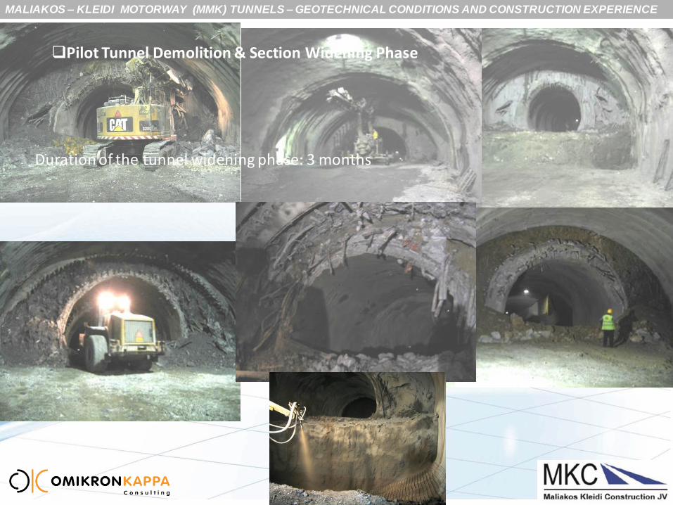
- 60 -
Pilot Tunnel Demolition & Section Widening Phase
Duration of the tunnel widening phase: 3 months
MALIAKOS – KLEIDI MOTORWAY (MMK) TUNNELS – GEOTECHNICAL CONDITIONS AND CONSTRUCTION EXPERIENCE
- 61 -
SPECIAL CONDITIONS IN TUNNEL T3
Tunnelling in CH.13+500 – Tunnel severe Under-profile - Tunnel Rehabilitation
Description of tunnel troublesome situation:
top heading excavation of the NB tunnel in very weak sheared peridotites GSI15 (with floating
megablocks of limestones and peridotites)
overburden 70m
variable excavation conditions (homogeneous vs. significantly heterogeneous excavation faces)
different modes of deformation (uniform sinking vs. differential movement of the shell foundation)
early development of high convergences and
under-performance of the initial lining (overstressing of the support elements) – tunnel under-profile
Sections affected: 50m
Need for : special rehabilitation design to re-instate the under-profiled section

MALIAKOS – KLEIDI MOTORWAY (MMK) TUNNELS – GEOTECHNICAL CONDITIONS AND CONSTRUCTION EXPERIENCE
- 62 -
SPECIAL CONDITIONS IN TUNNEL T3 -Tunnelling in CH.13+500 –Tunnel Rehabilitation
Heterogeneous conditions – differential sinking – shell overstressing
Homogeneous conditions – uniform sinking – no overstressing
Delayed deformations
Early deformations & subsequent creep

MALIAKOS – KLEIDI MOTORWAY (MMK) TUNNELS – GEOTECHNICAL CONDITIONS AND CONSTRUCTION EXPERIENCE
- 63 -
SPECIAL CONDITIONS IN TUNNEL T3 -Tunnelling in CH.13+500 –Tunnel Rehabilitation
Contingency measures to address severe deformation:
Use of 18m long (8/10) pre-stressed anchors 40tons & stiffening rings on the shell
Implementation of micropiles (6m)
use of micropiles – very limited effect
use of pre-stressed anchors halted the convergence gradients, but not the creep effect
MALIAKOS – KLEIDI MOTORWAY (MMK) TUNNELS – GEOTECHNICAL CONDITIONS AND CONSTRUCTION EXPERIENCE
- 64 -
SPECIAL CONDITIONS IN TUNNEL T3 -Tunnelling in CH.13+500 –Tunnel Rehabilitation
Requirements for the design of the Rehabilitation section:
i. a stiff and robust support in top heading (implemented by combination of
outer + inner sprayed concrete composite shells);
ii. no forepoling umbrella (since the converged section would provide the
required confinement around the cavity);
iii. ring closure in 8m rounds to result in favourable re-distribution of loads
around the cavity and catch up the tendency of early deformations;
iv. use of pre-stressed anchors (40tons, 18m long) to deal with the risk of
creeping due to rockmass relaxation overtime (and effect from the SB
excavation)

MALIAKOS – KLEIDI MOTORWAY (MMK) TUNNELS – GEOTECHNICAL CONDITIONS AND CONSTRUCTION EXPERIENCE
- 65 -
SPECIAL CONDITIONS IN TUNNEL T3 -Tunnelling in CH.13+500 –Tunnel Rehabilitation
Initial lining at the vault comprised: •an outer shell, a composite sprayed concrete lining 25cm thick with LG140/30/200 embedded per 0.50m rounds •an inner shell, a composite sprayed concrete lining 25cm with HEB180 arches embedded, in 1m rounds
MALIAKOS – KLEIDI MOTORWAY (MMK) TUNNELS – GEOTECHNICAL CONDITIONS AND CONSTRUCTION EXPERIENCE
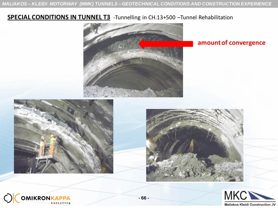
- 66 -
SPECIAL CONDITIONS IN TUNNEL T3 -Tunnelling in CH.13+500 –Tunnel Rehabilitation
amount of convergence
MALIAKOS – KLEIDI MOTORWAY (MMK) TUNNELS – GEOTECHNICAL CONDITIONS AND CONSTRUCTION EXPERIENCE
SPECIAL CONDITIONS ENCOUNTERED IN THE EXCAVATION & SUPPORT
- 67 -
Tunnelling was linked with significant face instabilities and the “short pilot tunnel”
method proved a viable solution to control.
The wide top heading sections proved very unfavourable in terms of the attracted
rock loading, which resulted in early deformations and extremely high convergence
rates;
Standard techniques suitable for normal tunnel sections (micropiles, temporary
invert) proved ineffective – use of pre-stress anchoring proved very effective,
instead.
Independently advanced drifts (top, bench and invert) did not prove effective
towards loads’ redistribution around the cavity, unless the bench & invert drifts are
kept as close as possible to the advancing top heading.
Significant experiences from NATM boring the 3-lane sections through weak geomaterials:
MALIAKOS – KLEIDI MOTORWAY (MMK) TUNNELS – GEOTECHNICAL CONDITIONS AND CONSTRUCTION EXPERIENCE
- 68 -
C O N C L U S I O N S:
Despite the relatively satisfactory level of the geotechnical investigation and executed
comprehensive risk assessment, several hazardous situations were unfolded in the 21.6 km
tunnelling;
Close collaboration between the Designers and the Construction JV resulted in quick
adaptation of the E&S methodology , processing of efficient solutions and modifications so as to
successfully address the increased geotechnical hazards.
The construction of MMK Tunnels represents the application of the NATM principles in a
significantly variable and very demanding hydro-geological and geotechnical environment;
Tunnel Designers had to elaborate competent and efficient designs for the Excavation and
Support and the Final Lining of the involved underground spaces.
MALIAKOS – KLEIDI MOTORWAY (MMK) TUNNELS – GEOTECHNICAL CONDITIONS AND CONSTRUCTION EXPERIENCE
- 69 -
Tunnelling started in August 2008 (Tunnel T2)
For tunnels T1 and T2 the civil works are fully completed
Significant delays were noticed due to works suspension period of two years
For Tunnel T3 E&S was recently completed (end of July 2014) and civil works are nearing to
complete
MALIAKOS – KLEIDI MOTORWAY (MMK) TUNNELS – GEOTECHNICAL CONDITIONS AND CONSTRUCTION EXPERIENCE
THANK YOU FOR YOUR ATTENTION